

Page 1

DENON
AV
SURROUND RECEIVER
AVR-2309CI
Owner's
Manuel
Manual
de
l'Utilisateur
Page 2

ENGLISH FRANCAIS
oSAFETY PRECAUTIONS
CAUTION
RISKOFELECTRIC
DO NOTOPEN
CAUTION:
TO REDUCE THE RISK OF ELECTRIC SHOCK, DO
COVER (OR BACK).
REFER
SERVICING TO QUALIFIED SERVICE PERSONNEL.
The lightning flash
triangle,
uninsulated "dangerous voltage" within the product's enclosure
that may be of sufficientmagnitude to constitute a risk of electric
shock to persons.
The exclamation point Within
to alert the user to the presence of important operating
and maintenance (servicing) instructionsinthe literature
accompanying the appliance.
NO
USER-SERVICEABLE PARTS INSIDE.
with
IS
intendedtoalert the user10the presence
arrowhead symbol, withinanequilateral
WARNING:
TO REDUCE THE RISK OF FIREORELECTRIC SHOCK, DO
EXPOSE THIS APPLIANCE TO RAINORMOISTURE.
SHOCK
A.
~
NOT
an
equilateral triangle is intended
REMOVE
NOT
SAFETY INSTRUCTIONS
1.
Read
Instructions - All the safety and operating instructions should be read
before the product
Retain Instructions - The safety and operating instructions should be
2.
retained for future reference.
Heed Warnings - All warnings on the product and
3
instructions should
Follow Instructions - All operating and use instructions should
4.
Cleaning - Unplug this product from the wall outlet before cleaning. Do not
5.
use liquid cleaners or aerosol cleaners.
Attachments -
6
manufacturer
Water and Moisture - Do not use this product near water - for example,
7.
near a bath tub, wash bowl, kitchen sink.orlaundry tub;ina
or near a
of
8
9
10.
11.
12.
swimming
Accessories - Do not place this product on
brac et. or table. The product may fall, causing serious injury to a child or
adult. and serious damagetothe product. Use only With a cart, stand,
tripod, bracket, or table recommended by
product. Any mounting of the product should
follow the manufacturer's instructions, and should
use a mounting accessory recommended by the
manufacturer.
A product and cart combination should be moved
with
care. Quick stops, excessive force, and
uneven surfaces may cause the product and cart
combination to overturn.
Ventilation - Slots and openingsinthe cabinet are provided for ventilation
and to ensure reliable operation
overheating, and these openings
openings should never be blocked by placing the product on a bed, sofa,
rug, or other similar surface. This product should not
Installation such
or
the manufacturer's instructions have been adhered to.
Power Sources - This product should be operated only from the type of
power source indicated on the marking label. If you are not sure of the ype
of power supply to your home, consult your product dealer or local power
company.
sources, refer to the operating instructions.
Grounding or Polarization - This product may be equipped With a polarized
alternating-current line plug
This plug will fit Into the power outlet only one way. This
If you are unable to insert the plug fully into the outlet, try reversing the
plug. If the plug should still fail to fit. contact your electriciantoreplace your
obsolete outlet. Do not defeat the safety purpose
EXAMPLEOFANTENNA GROUNDING
is
operated.
in
be
adhered to.
Do
not use attachments not recommended by the product
as
they may cause hazards.
pool; and the like.
as
a bookcase or rack unless proper ventilationisprovided
For
products intended to operate from battery power, or other
(a
plug having one blade wider than the other).
FIGURE A
AS
PER
NATIONAL
elECTRICAL CODE
elECTRIC
SERVICE
EQUIPMENT~---J
NEe·
NATIONAL ELECTRICAL CODE INEG ART 250. PART H)
n-
I
__
an
unstable cart, stand, tripod,
he
manufacturer, or sold
of
the product and to protectitfrom
must
not be blocked or covered. The
of
ANTENNA
LEAD
IN
WIRE
ANTENNA
DISCHARGE UNIT
(NEG SECTION 610·20}
POWER SERVICE GROUNDING
ELECTRODE SYSTEM
the operating
be
wet
be
placedina built-in
is
a safety feature.
the polarized plug.
followed.
basement;
with
13.
Power-Cord Protection - Power-supply cords should be routed so that they
are not likely
them, paying particular atten ion to cordsat plugs, convenience receptacles,
and the point where they exit from the product.
15.
Outdoor Antenna Grounding - Ifanoutside antenna or cable system
connected to the product,besure the antenna or cable systemisgrounded
soasto provide some protection against voltage surges and built-up static
charges. Article 810 of the National Electrical Code, ANSI/NFPA 70, provides
information with regardtoproper grounding of the mast and supporting
structure, grounding of the lead-in wire to
of
grounding conductors, locationofantenna-discharge unit. connection to
grounding electrodes, and requirements for the grounding electrode. See
Figure
16.
Lightning -
whenitis
or
from the wall outlet and disconnect the antenna or cable system. This will
the
prevent damage
17.
Power Lines - An outside antenna system should not be locatedinthe
vicinity of overhead power lines or other electric light or
where it
antenna system, extreme care should be taken
power lines or circuits
18.
Overloading - Do not overload wall outlets, extension cords, or Integral
convenience receptacles
19.
Object and Liquid Entry - Never push objects of any kind into this product
through openings
parts that could result
on the product.
20. Servicing - Do not attempt
removing covers may expose you
Refer all servicing to qualified service personnel.
21.
Damage Requiring Service - Unplug this product from the wall outlet
and refer servicing to qualified service personnel under the following
conditions:
a)
When
b)
If liquid has been spilled, or objects have fallen into the product,
cl
If the product
d)
If the product does not operate normally by following the operating
instructions. Adjust only those controls that are covered by the operating
instructionsasan
damage and will often require extensive work by a qualified technician to
restore the product to its normal operation,
e)
If the product has been droppedordamagedinany way, and
f)
When
indicates a need for service.
22. Replacement Parts - When replacement parts are required, be sure the
service technician has used replacement parts specified by the manufacturer
or have the same characteristics
substitutions may result
23. Safety Check - Upon completion
ask the service technician to perform safety checks
product is
24.
Wall or Ceiling Mounting - The product should be
ceiling onlyasrecommended by the manufacturer.
25. Heat - The product should
radiators, heat registers, stoves, or other products (including amplifiers) that
produce heat.
to
be walked on or pinched by items placed upon or against
an
antenna discharge unit. size
A.
For
added protection for this product during a lightning storm,
left unattended and unused for long periodsoftime, unplug it
to
the product duetolightning and power-line surges.
can
fall into such power lines or circuits. When installing an outside
as
contact
with
them mightbefatal.
as
this
can
resultina risk of fire or electric shock.
as
they may touch dangerous voltage points or short-out
in
a fire or electric shock. Never spill liquid of any kind
to
service this product yourselfasopening or
to
dangerous voltage or other hazards.
the power-supply cord or plug is damaged,
has
been exposed to rain or water,
improper adjustment of other controls may result
the product exhibits a distinct changeinperformance - this
as
in
fire, electric shock, or other hazards.
in
proper operating condition.
be
situated away from heat sources such
the original part. Unauthorized
of
any service or repairstothis product,
power
to
keep from touching such
to
determine that the
mountedtoa wall
is
circuits, or
in
or
as
Page 3

FRANCAIS ENGLISH
FCC
INFORMATION (For
1.
PRODUCT
This product complies with Part
product may not cause harmful interference, and
interference that may cause undesired operation.
2.
IMPORTANT NOTICE: DO NOT MODIFY THIS PRODUCT
This product, when installed
Modification not expressly approved by DENON may void your authority, granted by the
3. NOTE
This product has been tested
of the
FCC
residential installation.
This product generates, uses
with
that interference will not occur
television reception, which
correct the interference
• Reorient
• Increase the separation between the equipment and receiver.
• Connect the product into
• Consult the local retailer authorized to distribute this type of product
help.
Rules. These limits
the instructions, may cause harmful interference to radio communications. However, thereisno
or
relocate the receiving antenna.
15
of the
FCC
Rules. Operationissubject to the following
(2)
this product must accept
as
indicatedinthe instructions containedinthis manual, meets
and
found to comply with the limits for a
are
designed to provide reasonable protection against harmful interferenceina
and
can
radiate radio frequency energy
in
aparticular installation. If this product does cause harmful interference to radio or
canbedetermined by turning the product
by
one or moreofthe following measures:
an
outletona circuit different from that to which the receiverisconnected.
US
customers)
Class
and,
OFF
and
oranexperienced radioffV technician for
This Class B digital apparatus complies with Canadian ICES-003.
Cet appareil numerique de
la
classe
Best
conforme
ala
norme NMB-003duCanada.
two
any
conditions:
interference received, including
FCC
FCC,
to use the product.
(1)
this
requirements.
B digital device, pursuant to Part 15
if not installed and usedinaccordance
guarantee
ON,
the userisencouraged to try to
oNOTE ON USE I OBSERVATIONS RELATIVES A L'UTILISATION
•Donot let foreign objects into the unit.
•
Ne
pas
laisser des objets etrangers dans
I'appareil.
•Donot let insecticides, benzene,
thinner comeincontact with the unit.
Ne
pas
mettreencontact des insecticides,
du
benzene etundiluant avec I'appareil.
• Avoid high temperatures.
Allow for sufficient heat dispersion when
inarack.
installed
• Eviter des temperatures elevees.
Tenir compte d'une dispersion
suffisante lors
etagere.
de
de
I'installation sur une
Keep
the unit free from moisture, water,
•
and
dust.
• Proteger I'appareil contre I'humidite, I'eau
et
la
poussiere.
chaleur
• Unplug the power cord when not using the •
unit for long periods of time.
• Debrancher
lorsque I'appareil n'est
de
Ie
longues periodes.
cordon d'alimentation
pas
utilise pendant
and
• Handle the power cord carefully.
Hold the plug when unplugging the cord.
Ie
• Manipuler
precaution.
Tenir
cordon.
cordon d'alimentation avec
la
prise lorsdudebranchement
*
(For
du
apparatuses with ventilation holes)
•
Do
not obstruct the ventilation holes.
Ne
pas
obstruer
•
les
trous d'aeration
• Never disassemble or modify the unit
any way.
•
Ne
jamais demonteroumodifier I'appareil
d'une maniere
ou
d'une autre.
in
II
Page 4
ENGLISH
o
Contents
Getting
Accessories····.
Cautions
Cautions
About the Remote Control Unit· .
Inserting the Batteries·····
Operating Range
Part Names and Functions···································
Front Panel .
Display
Rear
Remote Control Unit
on
on
Panel·
Started
Handling···
Installation··
of
the Remote Control Unit··
..
.
.
..
·····3
.....
.
····5
·····7
Connections
Preparations··
Cables Used for Connections .
Video Conversion Function
On-Screen Display for Component Video Outputs and
HDMIOutput
Speaker Connections
Speaker Installation· ........
Speaker Connections....
Connecting Equipment
Connecting the Monitor.. .
Connecting the Playback Components·
Blu-ray Disc player / DVD player .
Record Player ·
CD Player . 14
iPod®·
TV/CABLE Tuner ·
Connecting the Recording Components ·15
Video Cassette Recorder
CD
Recorder /MDRecorder
Connections to Other Devices.. ..·16
Video Camera / Game Console ..16
Component
XM connector
SIRIUS connector· ··18
Antenna terminals
Multi-zone 20
External Controller..
Connecting the Power Cord.. .
Once Connections are Completed.. .
...
...
with
HDMI connectors.. ..·12
..
!Tape
with
Multi-channel Output connectors · ··17
..
Deck
·······9
·· ..·..
....
....·14
..
..
..
..
··21
Menu
Operations ·
Example of Display of Default Values·
Examples of On-screen Display and Front Display
·2
Menu
3
3
Operations
Map·
.. ··
· ····
3
Auto
3
Preparations
-4
Auto Setup
·4
6
Speaker Setup
8
8
9
10
10
HDMI Setup .
10
13
·13
13
·14
Audio Setup
15
15
16
ZONE2 Setup
17
19
20
21
Setup
..
o Auto Setup .
Error
Messages
fJ Parameter Check
Manual
Setup
o Speaker Configuration
fJ
Subwoofer
II
Distance ·
B Channel Level ·
Setup
..
..
..
..
·
..
III Crossover Frequency
III Front Speaker Setup ....
o Color Space
fJ RGB Range
II
Auto Lipsync
B
HDMI
III
HDMI
III
Power
o
EXT.INSubwoofer
fJ 2ch Direct/Stereo .
II
Dolby Digital Setup
B
Auto
III
EO
Preset
o Level Lch
fJ Level Rch
II
Volume Limit
B
Power
III
Mute
Audio
Control·
Off
Control
··
Surround
..
On Level
Level..·
..
Out
..
Mode
..
Level..·
..
.
........
··
···..··· ..
..
..
·36
....37
..··37
....
····39
·41
···41
..42
.... -42
..
..
·
..
..
...... ·46
..
·47
..
·49
......-49
..·..
..51
....
·35
..
·37
·39
·39
..41
·44
·44
·45
·45
·46
·51
35
35
36
36
36
37
39
39
43
43
45
47
51
Option Setup
o
Amp
..
·22
··..22
..
......
fJ Volume Control
II
B On-Screen Display
23
III Ouick Select
24
III Trigger
II
II
Assign
Source Delete
Name·
Out·
RemoteIDSetup·
232C Port··..·
mDisplay
1m
..
·
..
..
..
·29
..
29
·30
·30
31
··31
..
·31
..
32
··..·32
··32
..32
....32
..·32
..
32
....33
..... ·..33
..33
··..·33
·33
34
··34
··34
··34
35
35
..
·35
25
26
26
28
29
Setup Lock
Input
Settings Related to Playing Input Sources
Setup
o Auto Preset
..
·
fJ Preset Skip
II
Preset Name
B Video .
III Input
Mode
III Rename
II
Source Level ..........··..
II
Assign
..
·
miPod .
1m
Antenna Aiming
mParenral Lock ·
Surround
CD
Standard Playback
Surround Playbackof2-channel Sources
Playing Multi-channel Sources (Dolby Digital. DTS.
(1)
DSP Simulation
Q)
Direct
® Stereo Playback -45
Playback
Parameter
Adjusting the parameters··
Surround Parameter ·
Surround Parameter
Tone
Audyssey Settings
RESTORER·······················
Night
Audio Delay
Playback·
in
Mode
..
Modes
the
PURE
..
Playback·
DIRECT
..
Mode
..
.
....
etc)
..
1
Page 5

ENGLISH
Information
Status
o MAIN
fJ ZONE2 .
Audio Input Signal··
HDMllnformation·········,·
o HDMI Signal Information
fJ
Auto Surround
Quick Select,..·
Preset Station ·
ZONE
HDMI Monitor Information
Mode·
.
..
·
..
··,·····
·······52
·..53
..
....·53
..
Playback
Preparations
Turning the Power
Selecting the Input Source ·54
Operations During Playback ·54
Playing Video and Audio Equipment
Basic Operation· . ·55
Listening
Basic Operation
Presetting
Listening to Preset Stations........ · · ·56
Listening
Basic Operation..
Checking the XM Signal Strength and
Presetting Radio Stations (Preset Memory)
Listening to Preset Stations ·58
Searching Categories
Listening
Basic Operation............
Checking the SIRIUS Signal Strength and Radio
Searching Categories
Parental Lock· ·59
iPod@
Basic Operation.. .
Listening to Music 60
Viewing Still Pictures or Videos
to
toXMSatellite Radio Programs
to
Playback
On
FM/AM
Radio
SIRIUS Satellite Radio Programs· 58
Broadcasts·
Stations (Preset Memory)
Radio
on
the iPod .
ID
..
ID
··59
.. ..
..
..
..
..
.. ..
..
..
..·
....
..
..
··52
·53
··53
·54
..
·55
·57
·57
·57
·60
Remote
Main Remote Control Unit (RC-1099)
·52
·52
53
·53
Operating DENON Audio Components ·................ ..·65
Presetti
Operating Preset Components ·
Punch Through Function· 68
Sub Remote Control Unit
Amp
Control
ng
AssignIMulti-zone
Unit
Operations
· ·65
(RC-11
07)
Connections
Operations
Multi·zone Settings with the Amp Assign Function 69
Multi-zone Settings and Operations
54
Multi-zone Operations ..·72
55
55
56
56
Turning the PowerOnand
Selecting the Input Source· ..·72
Adjusting the Volume........
Turning off the Sound Temporarily.... ,72
Other
Information
Off..
with
Zone Output
Troubleshooting
58
Specifications
58
58
Listofpreset
59
59
codes
EndofthiS
·· .. ··
· 65
..
65
..
68
and
71
.. ..
·72
..
72
73
82
86
manual
Getting
Thank you for purchasing this DENON product.Toensure proper
operation, please read this owner's manual carefully before using the
product.
After reading them,
Started
be
sure to keep them for future reference.
Accessories
Check that the following parts are supplied with the product.
CD
Owner's manual......................
@ Getting Started ,.............
..
1
..
1
mWarranty (for North America model only) 1
@)
Service station list 1
® Power cord (Cord length: Approx. 6.2
® Main remote control (RC-l 099)....
(j)
R6/M
batteries (for RC-l 099).
®
Sub
remote control
®
@
(jJ)
R03/AM
FM
AM
batteries Ifor
indoor antenna
loop antenna ,.................
@ Setup microphone
(DM-A409, Cord length: Approx.
@
(RC-ll
RC-ll
07)...
07)
25ft/ 7.6m).
ft
/1.9
m)
..
1
.,
1
..
2
.1
..
2
..
1
..
1
..
1
®
I
Other
Other Operations
Recordingonan
Convenient Functions
HDMI Control Function
Channel Level..· .
Fader Function
Quick Select Function·
Personal Memory Plus Function
Last Function Memory
Backup Memory......·
Resetting the Microprocessor ........
Operations
External Equipment
and
..
..
Functions
..
IREC
..
OUT mode)
··
.. ·· ..·· ..
..................·
.. ·· ..
·····
..
··64
·,,··········64
···..····
..
....
.. ..
.. ..
..63
....
.. ·· ..·..
61
·61
62
62
63
·64
..
·64
64
2
Page 6

ENGLISH
I
Cautions
• Before turning the power switch on
Check once again that
no
problems with the connection cables.
• Powerissupplied to someofthe circuitry even when the unit
set to the standby mode. When traveling or leaving home for long
periods of time, be sure to unplug the power cord from the power
outlet.
• About condensation
If thereisa major differenceintemperature between the inside of
the unit
the operating parts inside the unit, causing the unit not to operate
properly.
If this happens, let the unit sit foranhour or
turned off
before using the unit.
• Cautionsonusing mobile phones
Using a mobile phone near this unit may resultInnoise. If
the mobile phone away from this unit when itisin
• Moving the unit
Turn off the power
outlet.
Next, disconnect the connection cables to other system units before
moving the unit.
• Note that the illustrationsinthese instructions may differ from the
actual unit for explanation purposes.
I Cautions
Note:
For proper heat dispersal, do not install this unit
space,
and
suchasa bookcase or similar enclosure,
on
Handling
all
connections
the surroundings, condensation (dew) may form
and
wait until thereislittle differenceintemperature
and
unplug the power cord from the power
on
Installation
are
correct
and
that there
two
with the power
use.
in
a confined
so,
are
on
move
I*Note
* O!ol_==TiO
00'=
0"
Q
••••
-
~:O:
_*_
About the Remote Control Unit
In
addition to the AVR-2309CI, the included main remote control unit
(RC-l099)
G)
@ Non-DENON system components
is
G)
@
® Put the rear cover back on.
can
DENON system components
•Bysetting the preset memory
also be used to operate the equipment listed below.
the Batteries
Lift the clasp
Load
battery compartment.
the
and
remove the rear lid.
two
batteries properlyasindicated by the marksinthe
(&page
65 -
67)
(RC-ll07)
(RC-ll07)
R03/AM
-N,Ua
• Replace the batteries with
even when the remote control unitisoperated closetothe unit.
• The supplied batteries
• When inserting the batteries, be sure to dosoin
following the
• To prevent damageorleakage of battery fluid:
•Donot use a
•Donot use
•Donot attempt to charge dry batteries.
• Do not short-circuit, disassemble, heat or disposeofbatteries
flames.
• If the battery fluid should leak, carefully wipe the fluid off the inside
of the battery compartment and insert
• Remove the batteries from the remote control unit if it will not be
use for long periods.
• When replacing the batteries,
insert themasquicklyaspossible.
II
uloerating Range of the Remote Co
Point the remote control unit at the remote sensor when operating
"EF>"
and
new
two
different types of batteries.
~/
o ,~
-<~/
Approx. 23 feet / 7 m
~
new
ones if the set does not operate
are
only for verifying operation.
"8"
marksinthe battery compartment.
battery together withanold one.
new
have
the
the proper direction,
batteries.
new
batteries ready
()
,f):
~
300
300
(RC-l099)
and
-Ntha
The set may function improperly or the remote control unit may not
operate if the remote control sensorisexposed to direct sunlight,
strong artificial light fromaninverter type fluorescent lamp or infrared
light.
in
in
It.
3
Page 7

Part Names and Functions
For
buttons not explained here, see the page indicatedinparentheses (
II
Front Panel
~
oPower operation button
···..
~
(17,
·(72)
..
(54)
(54)
64)
(64)
(ON/STANDBY)
8 Power indicator ·
..
Power switch
• Headphones jack (PHONES) (54)
o
INPUT
(.-.ON
MODE button··················
oSPEAKERS button
8Z0NE2
ON/OFF
..
· (54)
.OFF)
..·..
· · (25, 54)
button·..·
8 QUICK SELECT buttons· · ·
o
v.
AUX
INPUT connectors
Remove the
you want to use them.
000
cap
covering the terminals when
000
0)
~
(
!J
:0:
)
SETUP MIC jack..· (25)
41
MENU
~
RETURN button........
Q)
SELECT/ENTER knob ·..· ·(22)
,
•
The
operates
buttonsonthe remote control unit.
• The control functionsinthe same wayasthe
cursor
as
the cursor [> button when turned clockwise.
• The control functions
ENTER
).
button..·..· (22)
SELECT/ENTER
in
the same wayasthe cursor<]and [>
<]
button when turned counterclockwise,
button when pressed the knob.
knob
on
the main unit
SELECTI ENTER
in
the same wayasthe
ENGLISH
4E)
Cursor buttons (.6\7) (22)
4DMASTER VOLUME control
«9
AUDYSSEY DYNAMIC VOLUME
indicator ·
4B
HD
AUDIO indicator.. . (45)
4D
Master volume indicator
41)
Display
~
Remote control sensor ·..·..·..·(3)
tD
ZONE2/REC SELECT button (72)
~
SOURCE SELECT knob ·..........
@)
SOURCE button
~STATUS
~
DIMMER button·..· · (37)
~RESTORER
~
BAND button ·..· · · ·..· (55)
@)
SHIFT button..· ·..· · (56)
@)
PRESET buttons ·..· ·(56)
G)TUNING
~
MUL
..
(22)
button (52,57)
button······································
buttons
TEQ button ·..· · · ·(49)
knob
· (54)
..
· · · (50)
..
..
·..· ·..· ·(55)
~
DYNAMIC VOLUME button
*About Dynamic Volume
Audyssey Dynamic Volume
of large variations
television programs, commercials,
and
the soft
Audyssey Dynamic
Dynamic Volume
is
adjusted automatically, the perceived
response, tonal balance, surround impression,
and dialog clarity remain the same.
*About Dynamic
(54)
(54)
(51)
Audyssey DynamicEOsolves the problem of
deterioratingsound quality
by
taking into account human perception
room acoustics. Audyssey DynamicEOworks
tandem with Audyssey MultEO® to provide well-
balanced sound for every listener at
level.
@)
VIDEO SELECT button..·........·..·..........·..·
....
·........·..·...... (50)
™ solves the problem
in
volume level between
loud passages of movies.
EOTMisintegrated into
so
thatasthe playback volume
EQ
as
and
volumeisdecreased
between
any
bass
and
volume
..
(39)
I
in
4
Page 8
ENGLISH
Display
:.::::=:..===================
0<
..
'
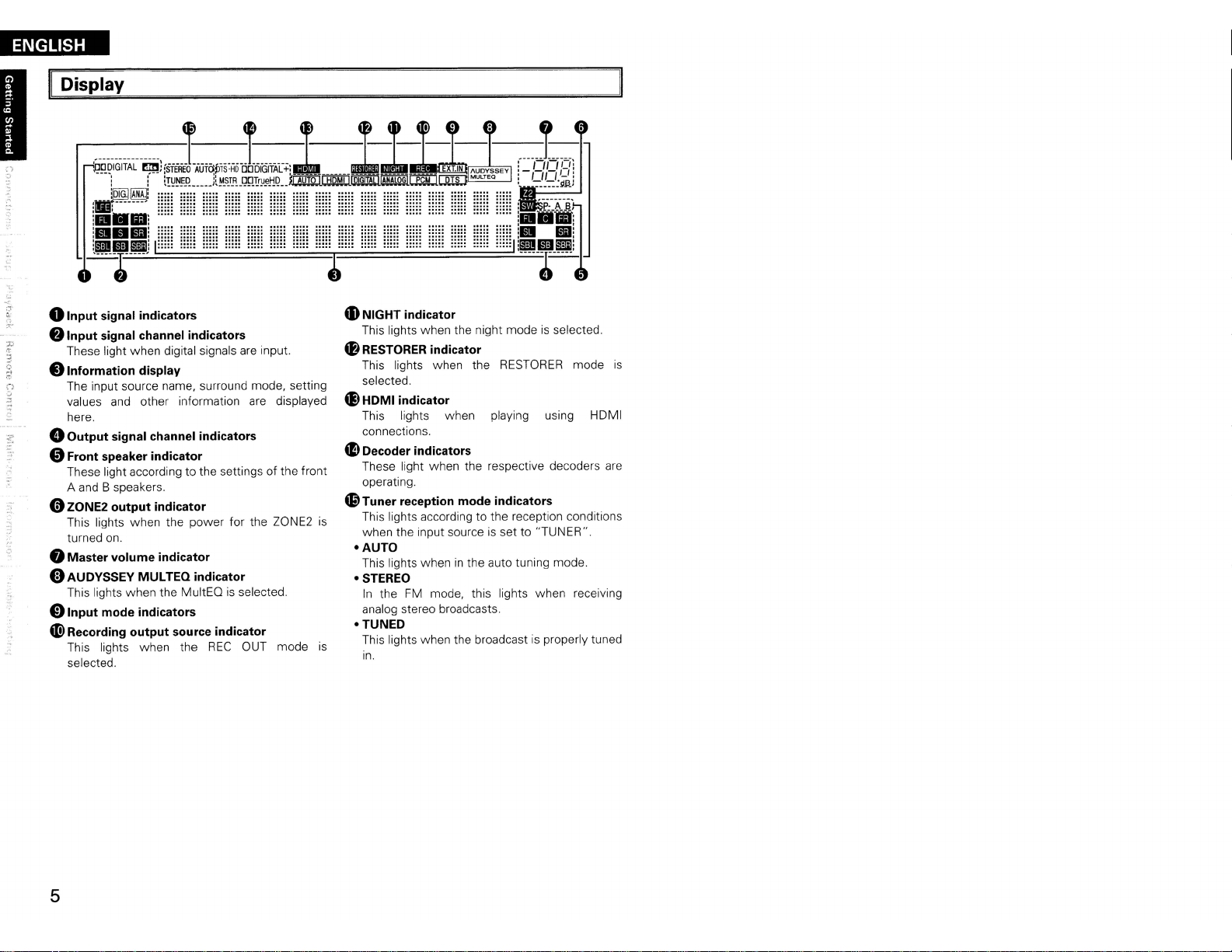
oInput signal indicators
:-f..
f)
Input signal channel indicators
These light when digital signals
•
Information
The input source name, surround mode, setting
values
here.
• Output signal channel indicators
display
and
other information
oFront speaker indicator
These light according to the settings of the front
A
and
B speakers.
oZONE2 output indicator
This lights when the power for the ZONE2
turned
on.
eMaster volume indicator
oAUDYSSEY MULTEQ indicator
This lights when the MultEQisselected.
01nput
ai)
mode indicators
Recording output source indicator
This lights when the
selected.
...............
.....
.....
...............
.....
.....
.....
.....
.....
.....
.
.
.
.
.
REC
.....
..... .....
.....
are
input.
are
displayed
OUT mode
....~.........
4D
NIGHT indicator
This lights when the night modeisselected.
4B
RESTORER indicator
This lights when the
selected.
~
HDMI indicator
This lights when playing using HOMI
connections.
~
Decoder indicators
These light when the respective decoders
operating.
Q.9
Tuner reception mode indicators
This lights according to the reception conditions
is
when the input source
-AUTO
This lights wheninthe auto tuning mode.
-STEREO
In
analog stereo broadcasts.
-TUNED
This lights when the broadcastisproperly tuned
is
in.
. .
. .
~HH
HH~
HH;
..
...
::::: ::::: :::::
the
FM
mode, this lights when receiving
HH~
RESTORER
is
set to "TUNER".
mode
is
are
5
Page 9

ar Panel
ENGLISH
I
STRAIGHT
ROOMTOROOMOC12V
[j[]
·@"""o··
...........
CABLE
REMOTE
ONTROl
[ilIJi
150rnA
MAX.
mm1'!IiiI!lm
c:::r
oRS-232C
f)
REMOTE CONTROL jack ·..·..· ·..···..·
..
TRIGGER OUT jacks
eDOCK CONTROL jack·································
oSpeaker terminals (SPEAKERS) (10)
0SIGNAL
.SIRIUS
connector·..· ········ ·····......··(20)
··..· (20)
GND
terminal
connector (SAT TU1) ·
·..· ·
(20)
(14)
(14)
(18)
v-----J
DOCK
CONTROL
8AC
o
4D>
"Analog
4BXM
"COMPONENT
.
inlet (AC IN) · · ·
AC
OUTLETS
Digital audio connectors
(OPTICAL I COAXIAL)
audio connectors (AUDIO)
connector (SAT TU2)..........·..·..·
VIDEO connectors..·..·
SPEAKERS
(13
- 16.
..
(14,
(13.15)
(21)
(21
18)
16)
(17)
)
SURROUND,CENTER.IFRONT
SURR.BACK,AMP
SATTU
1
SIRIUS
SIGNAL
GNO
~HDMI
~VIDEO
4D
4&
4DEXT. IN
4i)
connectors
IS-VIDEO
FMIAMantenna terminals
(TUNER ANTENNA) ·
ZONE2 connectors· · · · ·
connectors··..
PRE
OUT
connector
connectors·..
..
· · · (19)
· · ·..(17)
6"-160
·
SPEAKER
(12.
(13,
· ·
ASSIGNAOR
AtB 12"-160
IMPEDANCE
13,
15)
15.
16)
..
(20)
(10)
AC
OUTLETS
B 6"-160
r
····
FcSl
FcSl
:ldldi
....................•
AC
120V
SWITCHEO
60Hz
TOTAL
120W(1A.)
AC
IN
MAX.
··!
o
[~I::::J
:;.
.::.-
6
Page 10
ENGLISH
Remote Control Unit
o Main Remote Control
Front]
[
DENON
Unit
(RC-1099)
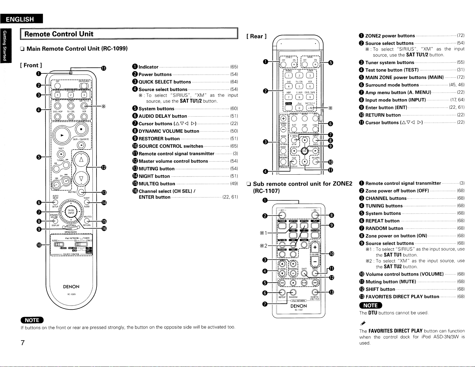
0 Indicator..
•
Power
.QUICK
.. ..
buttons··
SELECT buttons (64)
(65)
.
(54)
oSource select buttons·· (54)
*: To select "SIRIUS",
source, use the
oSystem buttons··
(l)AUDIO
.Cursor
DELAY button .
buttons
IE:.
eDYNAMIC VOLUME button
o
RESTORER
4DSOURCE CONTROL switches
tDRemote
4B
Master volume control buttons
~
MUTING button (54)
~
NIGHT
~
MUL
(9Channel
ENTER
button
control signal transmitter·.. .
button···················
TEQ
button·
select
(CH
button··
SAT
\7<1
SEL)
"XM"
TU1/2
1»
/
as
button.
the input
(601
..
(511
(221
(50)
(51)
(651
(541
(51)
(49)
(22, 61)
[
Rear]
(3)
o Sub remote control unit for ZONE2
(RC-1107)
O---~
oZONE2 power buttons
8 Source select buttons.. . .
*: To select "SIRIUS",
source, use the
SAT
"XM"
TU1/2
as
button.
oTuner system buttons··
oTest tone button (TEST)··
oMAIN ZONE power buttons (MAIN)
(72)
..
(541
the input
(551
(311
.....
(721
oSurround mode buttons··· ..... (45, 46)
8 Amp menu button IA.
oInput mode button (INPUT)
oEnter button (ENT)··
«!>
RETURN button·· .
4D
Cursor buttons
oRemote control signal transmitter (3)
8 Zone power off button (OFF)· (68)
(E:.
\7
MENU)·
<I
1»
.....
(17.
(22,
(221
64)
61)
(22)
(22)
oCHANNEL buttons (68)
oTUNING buttons (68)
oSystem buttons··
o
REPEAT
button·· (68)
8 RANDOM button·· (68)
oZone power
on
button (ON) (68)
oSource select buttons··
*1:To
select "SIRIUS"asthe input source, use
the
SAT
TU1
*2:
To select
the
SAT
«!>
Volume control buttons (VOLUME) (68)
4D
Muting button (MUTE) .
~
SHIFT
button····
til
FAVORITES DIRECT PLAY button (68)
button.
"XM"asthe input source, use
TU2
button.
..
·
..
(68)
..
(68)
..
(68)
..
(68)
-~['iia
If buttonsonthe front or rear
7
are
pressed strongly, the button on the opposite side willbeactivated too.
-N·na
The
DTU
buttons cannot be used.
The
FAVORITES
"
when the control dock for iPod ASD-3N/3W
used.
DIRECT
PLAY
button
can
function
is
Page 11
Connections
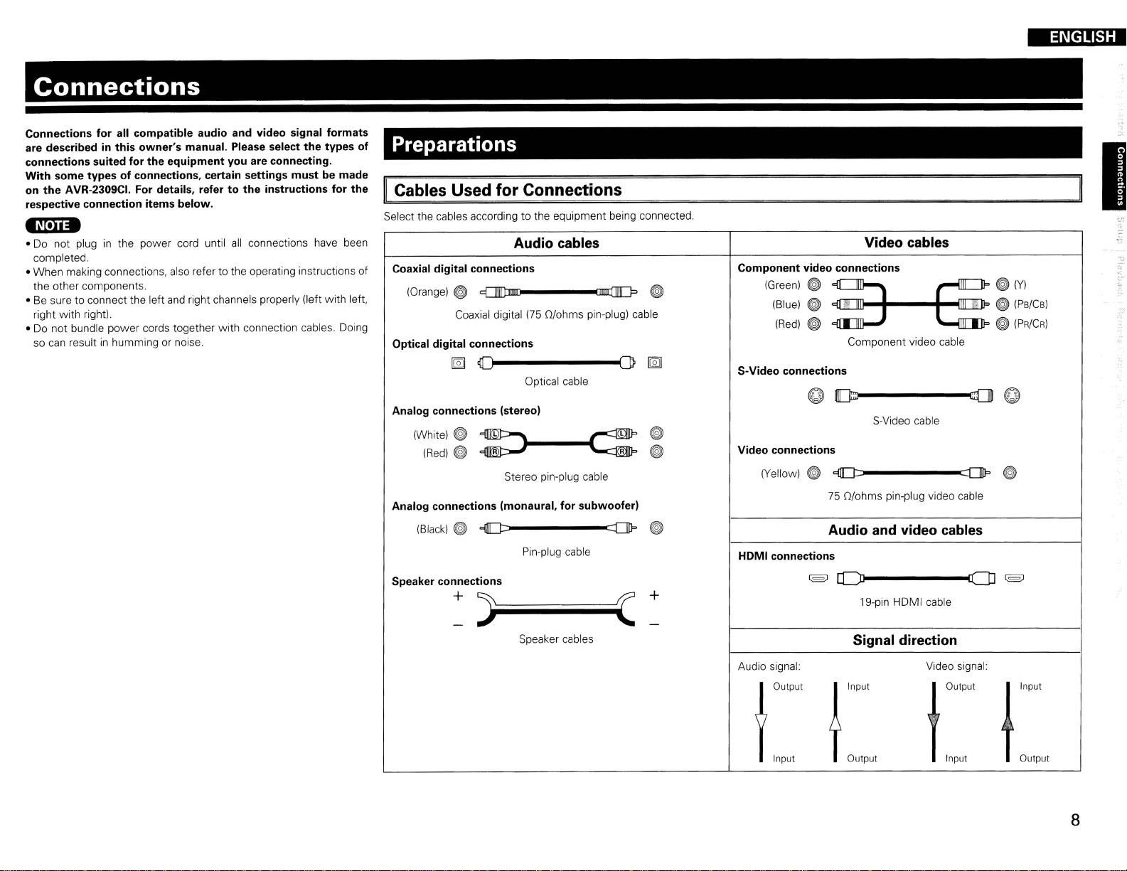
Connections for all compatible audio and video signal formats
are describedinthis owner's manual. Please select the types of
connections suited for the equipment you are connecting.
With some types of connections, certain settings must be made
on the AVR-2309CI. For details, refer
respective connection items below.
-Nina
• Do not pluginthe power cord until
completed.
•
When
making connections, also refer to the operating instructions
the other components.
• Be sure to connect the left and right channels properly (left
right
with
right).
• Do
not
bundle
power
so can result
in
cords together
humming or noise.
to
the instructions for the
all
connections have been
with
connection cables. Doing
with
left.
Preparations
Cables Used for Connections
Select the cables according to the equipment being connected.
Audio cables
Coaxial digital connections
of
(Orange)~
Optical digital connections
~
Coaxial digital
~
~~-------(JP
(75
O/ohms pin-plug) cable
Optical cable
[g]
ENGLISH
I
Video cables
Component video connections
~
(Green)
S-Video connections
(Blue)
(Red)
~
~
~
Component video cable
~(Y)
~
(Ps/Cs)
~
(PR/CR)
Analog connections (stereo)
(White)
~
~~
(Red)
~
~
Stereo pin-plug cable
Analog connections (monaural, for subwoofer)
(Black)
~
e::tJ][J::::------::D1J='
Pin-plug cable
Speaker connections
+
)~Iiiiiiiiiiiiiii(
Speaker cables
~
~
+
Video connections
(Yellow)
HOMI connections
Audio signal:
~
(§J
AOutput
flnput
S-Video cable
e::tJ][J::::------::DIlP
75
O/ohms pin-plug video cable
Audio and video cables
rL)l-------CD
19-pin HDMI cable
Signal direction
Video signal:
j
Input
Youtput
Output
Input
~
(§J
J
Input
TOutput
8
Page 12

ENGLISH
II
Video Conversion Function
• This function automatically converts various formats of video signals input to the AVR-2309CI into the
format used to output the video signals from the AVR-2309CI to a monitor.
• The AVR-2309CI's video input/output circuitry
signals:
Digital video signals: HOMI
Analog video signals: Component video, S-Video
[Flow of video signals inside
High picture
quality playback
I~
"=-,-------.:==-'
I"
I
J
r--1
I~
1
J1
o-I=---'='''
l§l
HOMI connector
Y
PB/C8
GGG
Component video
connectors
~
~
S·V;d"
G
Video connector
Video input
terminals
- - - - : When 480i/576i signals are input
is
compatible
and
Video
PRiCR
/ /
::"
'<>"
j"',/"'"
V"~,"~
---.~
,oo"otO~
with
the
AVR-2309CI]
c>
/11
/ ·
/
"'",
the following four types of video
HOMI connector
Y
PB/C8
GGG
Component video Monitor
connectors
o . !
S-Video connector
G
Video connector
Monitor output
terminals
PRiCR
.0'.1
On-Screen Display for Component Video Outputs and
VULJJut
• When viewing HOMI or component video signals
when the
• When only HOMI or component video signals
screen display
'
...
MENU
are
on
the main unit or the
not displayed over the picture.
A.MENU
are
HDMI
via
the AVR-2309CI, the on-screen display appears
buttononthe main remote control unitisoperated.
input to the AVR-2309CI, the characters of the
on-
• When not using this function, connect a monitor output with the same type of connector
input connector.
• The resolution of the HOMI input-compatible monitor connected to the AVR-2309CI
menu "Information" -
"HOMllnformation"
(I(ff'page
53).
canbechecked at
IN,U.
• HOMI signals cannotbeconverted into analog signals.
• 1080p component input video signals cannot
connectors.
• 480p/576p, 1080i and
format.
• When a non-standard video signal from a game machine or some other source
conversion function might not operate.
nop
component video input signals cannotbeconverted into S-Video or Video
be
output to anything other than component video
is
input. the video
9
as
the video
Page 13
Speaker Connections
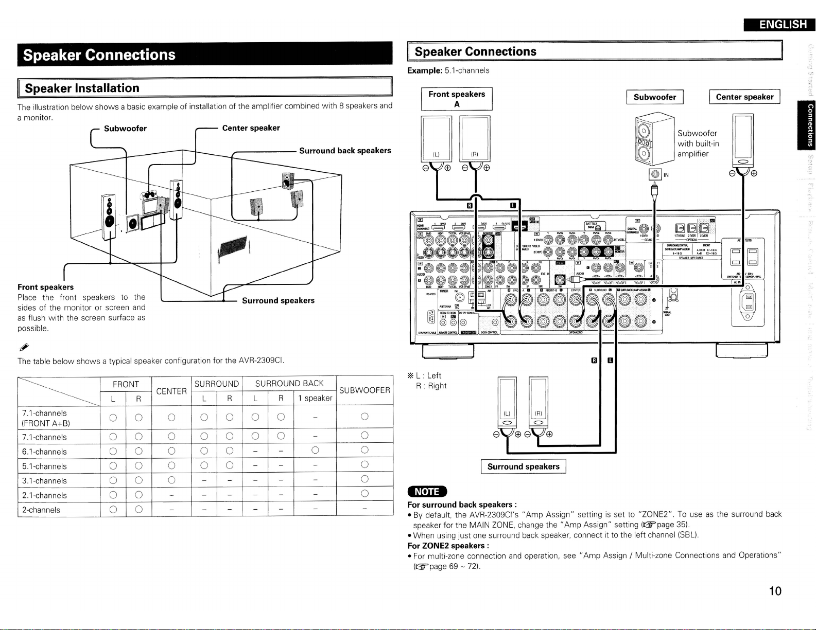
Speaker Installation
The illustration
a monitor.
Front speakers
Place the front speakers to the
sides of the monitor or screen and
as
flush
possible.
below
with
the screen surface
shows
a basic exampleofinstallationofthe amplifier combined
Subwoofer
as
---------
Center speaker
_-----
Surround speakers
with
8 speakers and
Surround back speakers
II
Speaker Connections
Example: 5.1-channels
Front speakers
A
DO
e
Subwoofer
~IN
Subwoofer
with
built-in
amplifier
ENGLISH
Center speaker
o
e
(±)
b[d
"C"
leoHr
!lWI"ftHIITO
1_1AjlWt
.~
'.-
I
The table
below
~
7.1-channels
(FRONT A+B)
7.1-channels
6.1-channels
5.1-channels
3.1-channels
2.1-channels
2-channels
shows
a typical speaker configuration for the AVR-2309CI.
FRONT SURROUND
L
R
CENTER
L
0 0 0 0 0 0
0 0 0 0 0
0
0 0 0 0 0
0 0 0 0
0
0
0
0
0 0
0
0
-
- -
-
-
SURROUND BACK
R
L
-
-
-
-
-
-
- -
-
1 speaker
R
0
0
-
- -
-
-
-
-
0
-
-
-
SUBWOOFER
0
0
0
0
0
0
-
*L : Left
R : Right
o0
e
(±)
e
(±)
Surround speakers I
-N'U-
For surround back speakers:
• By default, the AVR-2309CI's
speaker for the MAIN ZONE, change
• When using just one surround back speaker, connect it to the left channel (SBL).
For ZONE2 speakers:
• For multi-zone connection and operation,
(ll25"page 69 - 72).
"Amp
Assign"
the"
Amp
see"
settingisset to
Assign" setting (ll25"page 35).
Amp
Assign / Multi-zone Connections and Operations"
"ZONE2".
To useasthe surround back
10
Page 14
ENGLISH
I
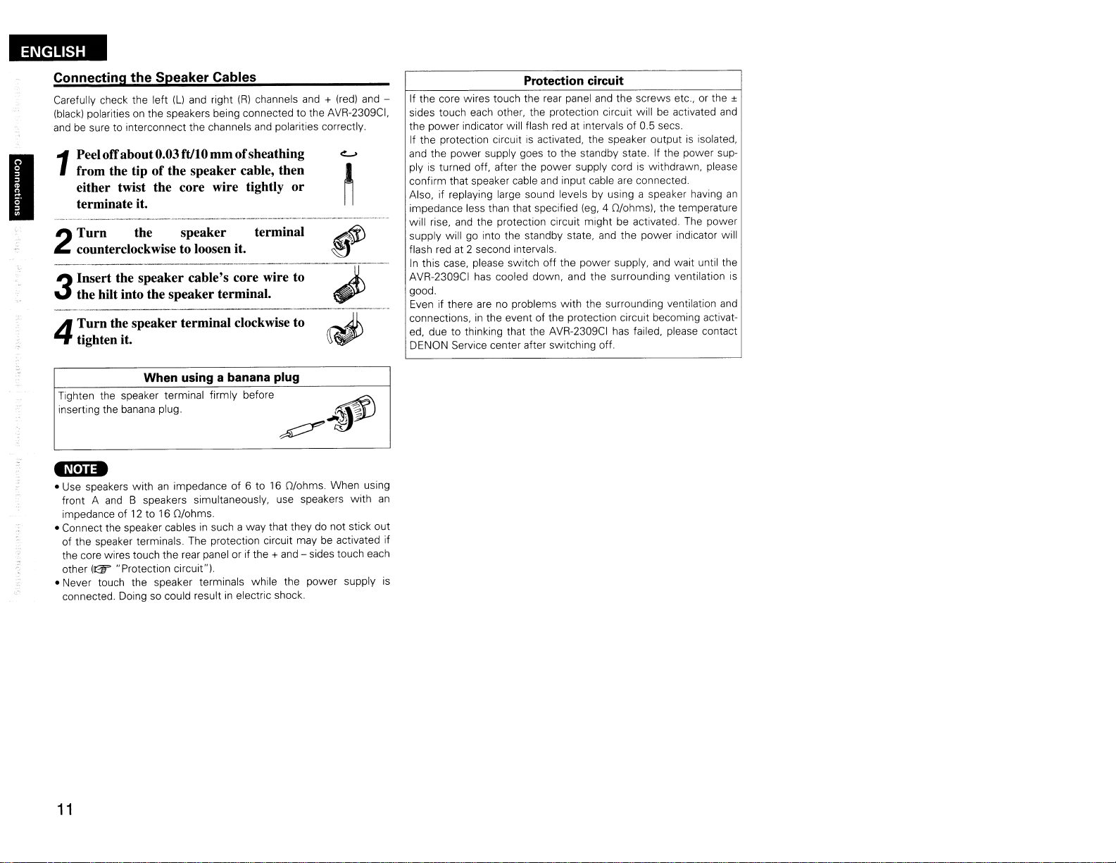
Connecting the Speaker Cables
Carefully check the left (Ll
(black)
polarities on the speakers being connected to the AVR-2309CI,
andbesure to interconnect the channels and polarities correctly.
Peeloffabout0.03ftJI0 mmofsheathing
from the tip
1
either twist the core wire tightly or
terminate it.
Turn the speaker terminal
2
counterclockwise to loosen it.
Insert the speaker cable's core wire to
the hilt into the speaker terminal.
3
Turn the speaker terminal clockwise to
4
tighten it.
When using a banana plug
Tighten the speaker terminal firmly before
inserting the banana plug.
-Nei
••
• Use speakers withanimpedance of 6 to16O/ohms. When using
front A
impedanceof12
• Connect the speaker cablesinsuch a way that they do not stick out
of the speaker terminals. The protection circuit maybeactivated if
the core wires touch the rear panel or if the +
other
• Never touch the speaker terminals while the power supply is
connected. Doing so could resultinelectric shock.
and
B speakers simultaneously, use speakers with
to 16 O/ohms.
(Gf'
"Protection circuit").
and
right
(R)
channels
of
the speaker cable, then
and
+ (red)
,
._-------
~~
and
~
~
~
~""
~J\
- sides touch each
and
"3;
;>
an
Protection circuit
-
If the core wires touch the rear panel
sides touch each other, the protection circuit will be activated
the power indicator will flash red at inteNals of 0.5 secs.
If the protection circuitisactivated, the speaker outputisisolated,
and
the power supply goes to the standby state. If the power supplyisturned off, after the power supply cordiswithdrawn, please
confirm that speaker cable
Also, if replaying large sound levels by using a speaker having
impedance less than that specified
will rise,
supply will go into the standby state, and the power indicator will
flash red at 2 second intervals.
In
AVR-2309CI has cooled down, and the surrounding ventilation
good.
Even if there
connections,inthe event of the protection circuit becoming activated, due to thinking that the AVR-2309CI has failed, please contact
DENON Service center after switching off.
and
the protection circuit might be activated. The power
this case, please switch off the power supply,
arenoproblems
and
and
the screws etc., or the ±
input cable
with
are
connected.
(eg,
4 O/ohms!. the temperature
and
the surrounding ventilation
wait until the
and
an
is
and
11
Page 15

Connecting Equipment
With
HDMI connections, the video
Blu-ray
player
l
DVD
player
HOMI
OUT
~
Disc
/
and
J
audio signals
[J
~
with
can
Monitor
HOMI
IN
~
~
HDMI connectors
be transferred with a single cable.
-nln-
• The AVR-2309CI cannot be controlled from another device
• The audio signals output from the HDMI connector (sampling frequency, bit rate, etc.) may be restricted
by the connected device.
• Video signals are not output properly when using devices that are not HDCP-compatible.
• Video signals are not output if the input video signals do not match the monitor's resolution.
case, switch the Blu-ray Disc player /
compatible.
·If
the menu "Manual Setup" -
"AMP",
the sound maybeinterrupted when the monitor's poweristurned off.
• Use a cable
connector. Normal playback may not be possible when using a cable other than one
logo
• If the monitor or Blu-ray Disc player /
is
not possible.
• If the monitor or Blu-ray Disc player /
possible.
• If the monitor does not
• The AVR-2309CI
note the following.
• It may not work depending
• It does not operate
on
which the HDMI logoisindicated(acertified HDMI product) for connection to the HDMI
is
indicated(anon-HDMI-certified product).
support"
is
compatible with the HDMI's
on
with
televisions or players that are not compatible with
DVD
player's resolution to a resolution with which the monitor
"HDMI
Setup" -
DVD
player does not support Deep Color, deep color signal transfer
DVD
player does not support xvYCC,
Auto Lipsync Correction" function, this function will not work.
the device itisconnected to
CEC
via
the HDMI cable.
"HDMI
Audio
Out"
setting
(Gr'page
xvYCC
(Consumer Electronics Control) function. Please
and
its setup.
HDMl's
32)isset to
on
which the HDMI
signal transferisnot
CEC.
In
this
is
I
f.
-.
*The AVR-2309CI
version 1.3a. This version
with
other versions, allowing connection
to
all
components equipped withanHDMI
connector.
*The AVR-2309CI
36-bit Deep Color.
is
equipped for HDMI
is
is
compatible with 30- and
::Jt;.
• By default, the HDMI audio signals
• To output the sound from the
Audio
Out"-"TV"
(Gr'page
TV,
32).
compatible
are
output from the speakers connected to the AVR-2309CI.
make the settings at menu "Manual Setup" -
Compatible
audio
format
2-channel linear
PCM
Multi-channel
linear PCM 16/20/24 bits
Dolby Digital,
Dolby Digital
DolbyTrueHD, Bitstream
DTS-HD
DTS
Plus,
Details
2ch
32-192 kHz
16/20/24 bits
8ch
32-192 kHz
Bitstream
"HDMI
Discs
(examples)
CD,
DVD-Video,
DVD-Audio
DVD-Audio,
Blu-ray
DVD-Video
Blu-ray
Setup" -
"HDMI
• When the AVR-2309CI
connect the AVR-2309CI
• If the connected monitor or Blu-ray Disc player /
converter cable.
• Use a Deep Color compatible cable for connection to Deep Color compatible devices.
When connecting
• HDMI video signals are theoretically compatible with the
When connecting to a monitor, etc., equipped with a DVI-D connector, connection
HDMI/DVI converter cable, but dependingonthe combinationofcomponentsinsome cases the video
signals will not be output.
• When connecting using
due to poor connections
In
order to play the digital video
DVI
connections, both the connected Blu-ray Disc player /
a copyright protection system
HDCP
is
devices.
The AVR-2309CI
are using, refer to its operating instructions.
a copy protection technology consisting of data encoding and mutual identificationofthe
and
Blu-ray Disc player /
and
monitor usinganHDMI cable.
When using a DVI cable, no audio signals are transmitted.
withanHDMI/DVI
an
HDMI/DVI converter adapter, the video signals may notbeoutput properly
with
the connected cable, etc.
Copyright protection system (HDCP)
and
audio signals of a Blu-ray, DVD- Video or DVD-Audio disc using
called"
HDCP" (High-bandwidth Digital Content Protection).
is
HDCP-compatible.
For
DVD
player are connected usinganHDMI cable, also
DVD
player only
detailsonthe Blu-ray Disc player /
has
a DVI-D connector, useanHDMI/DVI
converter cable (adapter)
DVI
format.
DVD
player
and
monitor
is
possible using
must
be equipped for
DVD
player or monitor you
an
HDMI/
12
Page 16

ENGLISH
I
Connecting the Monitor
• Select the terminal to use
• With HDMI connections, the video
•Tooutput the audio signals to the monitor with HDMI connections, set menu "Manual Setup" Setup" -
"HDMI
Audio Out" to "TV"
and
Monitor
HDMI
IN
connect the device
and
audio signals
(&page
-----VIDEO
S VIDEO COMPONENT VIDEO
VIDEO
IN
IN
(&page
32).
9 "Video Conversion Function").
canbetransferred with a single cable.
-----
IN
YP8PR
eee
aM
......._.011'
-1-
1~1"1
....
110
...
·1
11-IIQ
[d[d
N;':llI'I'D<!
SlIlItIO~llOW1l.l.l'"""'
"e
"HDMI
Connecting
Carefully check the left (L) and right
correctly.
II
Blu-ray Disc player I DVD player
Select the terminal to use and connect the device.
Blu-ray Disc player / DVD player
-----VIDEO
HOM!
OUT
r - ..
I~I
~~~+=i~~~~""'i-:.,...=-
VIDEO
Olir
the
Playback Components
(R)
channels and the inputs and outputs, andbesure to interconnect
S VIDEO
OUT
-----
COMPONENT
OUT
YPBPR
--AUDIO--
VIDEO
eee
""""i-......
Q mOO-8
~~~~~(@)~(@)(@)o
~
'"(j"
~ ~
~
(®)
AUDIO COAXIAL
OUT OUT
L R
ee
(®)
(®)
e
(@)
* When connected to a Blu-ray
Disc player,
TrueHD, DTS-HD, Dolby Digital
PlusHDAUDIO, connect the
HDMI.
-1-
SMIAlXM_
''''\10
~Nl'tDoUltf
~
II
and
playing Dolby
lOIlII
...
110
"'"
11"'IIQ
[d[d
SIIIlDtilWIAI.Imf(IJJlIUC
"e
.~[.J'.
• The component video connectors maybeindicated differentlyonyour monitor. For details, see the
monitor's operating instructions.
• The audio signals output from the HDMI connectors are only the HDMI input signals.
13
When usinganoptical cable for the digital audio connection, make the settings at menu "Input Setup"
- "Assign" -
"Digitalin"
(&page
42).
Page 17
ENGLISH
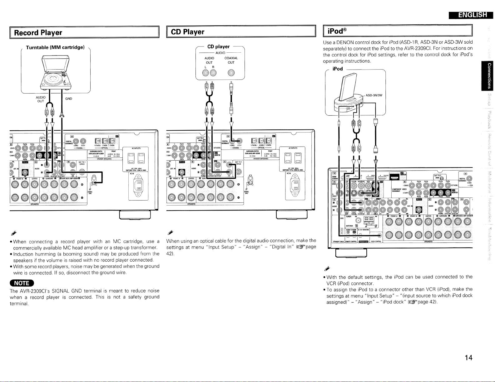
Record Player
Turntable
(MM
cartridge)
Sl.M<>.OI\C9ITtI\/
S1JlR.BllQ(,MA$SIGIf
'''10'60••811"'1150
SP().QRIMPiOANCE
AOR85
-.
....
1I0
$MT()(OTOTAl.12OWjlA.11I6U.
~~
ACl2OV~
'C
CD Player
CD
player
--AUDIO-AUDIO COAXIAL
OUT OUT
L R
GG
G
(®)@(@)@~@@
@(@)@@(@)@(@)
II
iPod®
Use a DENON control dock for
separately) to connect the
the control dock for
operating instructions.
iPod
iPod
ASD-3N/3W
iPod
iPod
settings, refer to the control dock for iPod's
(ASD-lR,ASD-3N or ASD-3W sold
to the AVR-2309CI. For instructions
on
I
r:1
.1
~.,
~bJ
N;12OY5OHI:
SllIImHOTDTALI2QW(lA,J1MX.
0
'='
<>
'C
• When connecting a record player withanMC cartridge, use a
commercially available MC head amplifier or a step-up transformer.
(a
• Induction humming
speakers if the volume
• With some record players, noise may be generated when the ground
is
connected. If so, disconnect the ground wire.
wire
booming sound) maybeproduced from the
is
raised with no record player connected.
-N·n.
The AVR-2309CI's SIGNAL
when a record player
terminal.
GND
is
terminalismeant to reduce noise
connected. Thisisnot a safety ground
I
When usinganoptical cable for the digital audio connection, make the
settings at menu "Input Setup" - "Assign" - "Digital In"
42).
I
(~page
• With the default settings, the iPod
VCR
(iPod)
connector.
To
assign the iPod to a connector other than
•
settings at menu "Input Setup" - "(input source to which
assigned)" - "Assign" - "iPod dock" ((W'page 42).
can
be used connected to the
VCR
(iPod),
make the
iPod
dock
14
')'
Page 18
ENGLISH
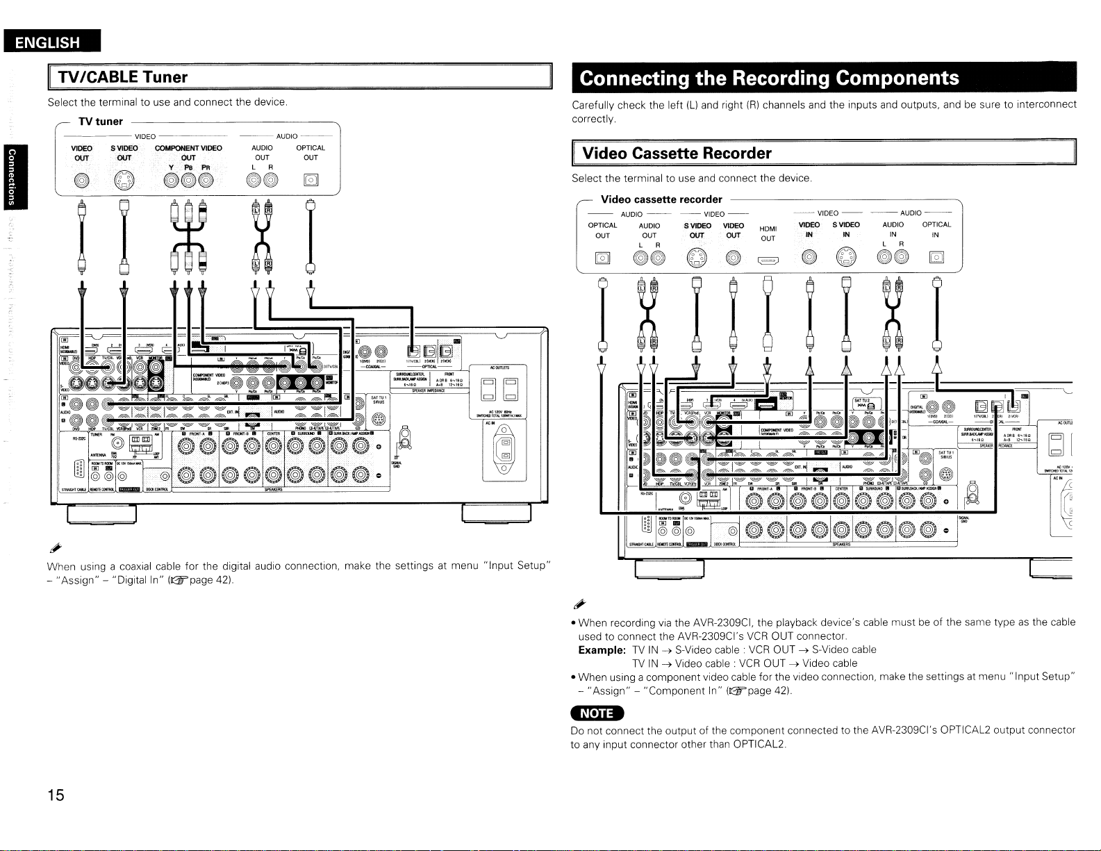
TV
Select the terminal to use
-----VIDEO
~
'------=------,--------,--,--------:-.../
I
; l
ICABLE Tuner
TV
tuner
S VIDEO COMPOI'll'NT VIDEO
VIDEO
-----
ovr ovr
;
and
connect the device.
y-
l'8
PR
eGG
--AUDIO-AUDIO OPTICAL
OUT OUT
L A
GG
bJbJ
1oI;1"",1OttI:
IW!It>8l11'L'tl~
__
Connecting the Recording Components
Carefully check the left (L)
correctly.
Video
Select the terminal to use
--
OPTICAL AUDIO
Cassette Recorder
Video cassette recorder
AUOIO-~
OUT OUT
L A
~~
and
right
and
connect the device.
--VIOEO--
SVIDEO
ovr
VIDEO
ovr
(R)
HOMt
OUT
channels
and
the inputs
--VIDEO-
VIDEO S VIDEO
IN
IN
and
outputs, and be sure to interconnect
--AUDIO--
AUDIO OPTICAL
IN IN
L A
~~
~
'C
When using a coaxial cable for the digital audio connection, make the settings at menu "Input Setup"
-
"Assign"-"Digitalin"
15
(D2!rpage 42).
• When recording
used to connect the AVR-2309CI's
Example:
• When using a component video cable for the video connection, make the settings at menu "Input Setup"
-
"Assign"
via
the AVR-2309CI, the playback device's cable mustbeof the same typeasthe cable
TV
IN~S-Video cable.
TV
IN~Video cable:
- "Component In" (D2!rpage
VCR
VCR
VCR
OUT connector.
OUT~S-Video cable
OUT~Video cable
42)
'Nelia
Do
not connect the output of the component connected to the AVR-2309CI's OPTICAL2 output connector
to any input connector other than OPTICAL2.
Page 19

II
CD Recorder I
Make analog connections if you wish to record analog audio signals, or digital connections if you wish to
record digital audio signals, depending
MD
Recorder I Tape Deck
on
the types of connectorsonthe components being used.
CD recorder /
MD
Tape deck
--AUDIO--
~~
recorder /
AUDIO AUDIO
OUT
L R L R
IN
GG
I=====~-----'~
EJEJllB-
1(JV.Ql};:
2t\UU
~-c==------.,
~I:.o:~::~
SPEmRIMPEDAHCE
~~
SWfJOIDroTAl12OW(1A.)~
Connections
Carefully check the left
correctly.
Video Camera I Game Console
q
to
Other Devices
{Ll
and
right
(R)
channels
I.-~
--,,-
and
the inputs and outputs,
Video camera / Game console
--
VIDEO
--
S
VIDEO VIDEO
OUT
C
---
OUT OUT OUT
~
I I X I
-
~~
~~~J
andbesure to interconnect
AUDIO--
AUDIO OPTICAL
L R
GG
~
~D
I
'0
---
o@
16
Page 20

ENGLISH
I
Component with Multi-channel Output connectors
Blu-ray Disc player / DVD player /
External decoder
FRONT CENTER
SUB·
WOOFER BACK
~
L R
~~
AUDIO
SURROUND SURROUND
L
~
~~
R
R
L
~~
lIiMIAtlt.W.-
-1-
,..liDI..
.....
...
OAI
IIZ..I$P
....
l.g
bdbd
"e.2CI\I1Dlt
_1WII.UOItIOJ_
"e
XM
connector
• The AVR-2309CIisan
XM Mini-Tuner
service.
•
Plug
the XM Mini-Tuner and Home Dock into the XM connector on the rear panel.
• Position the Home Dock antenna near a south-facing
For details,
When making connections, also refer to the operating instructions of the XM Mini-Tuner
Dock.
see"
XM
Mini-Tuner and
XM Ready® receiver.
and
Home Dock (includes home antenna, sold separately) and subscribing to the XM
Listening to XM Satellite Radio Programs"
Home
Dock
You
can
receive XM® Satellite Radio by connecting to the
window
to receive the best signal.
(@"page
56 -
58).
-1-
~~"011''''l'O
,..tIll
,tI,1
11"-IUI
........
"""'"
and
bdbd
$IIfIt»OJIIllltnfllU,JliIll,.
Home
• To play the analog input signals input to the
main unit or
menu "Input Setup" -
• The video signal canbeconnectedinthe same wayasa Blu-ray Disc player /
INPUT
buttononthe main remote control unit and select "EXT.
"Input
Mode"
EXT.INconnectors, press the
- "Input
Mode"
- "EXT. IN" (GT'page 41).
17
INPUT
MODE
IN"
or make the settings at
DVD
button on the
player (GT'page
13).
-N,lI.
Keep the power cord unplugged until the XM Mini-Tuner
completed .
• The XM name
reserved.
• XM Ready®isa registered trademarkofXM Satellite Radio Inc. All rights reserved.
and
related logo
are
registered trademarksofXM Satellite
"0
and
Home Dock connection have been
Radio
Inc. All rights
Page 21
ENGLISH
II
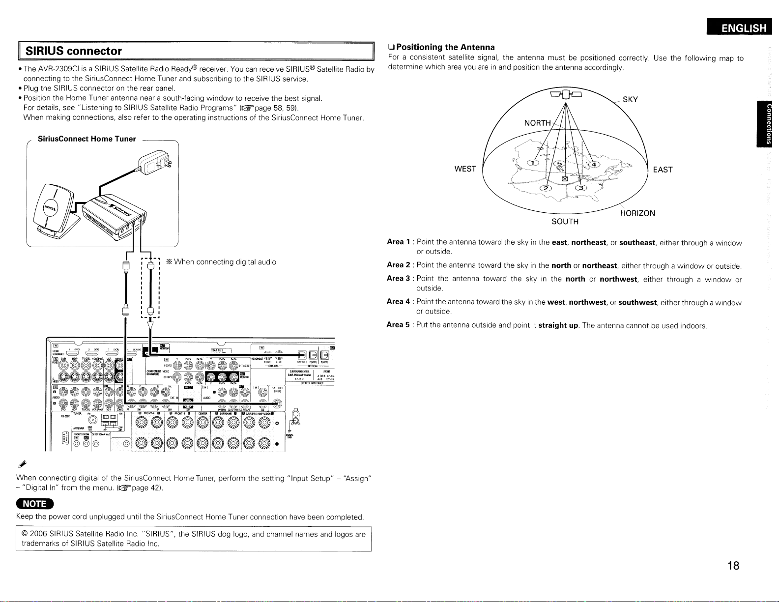
SIRIUS connector
• The AVR-2309CIisa SIRIUS Satellite Radio Ready® receiver.
connecting to the SiriusConnect Home Tuner and subscribing to the SIRIUS service.
•
Plug
the SIRIUS connector on the rear panel.
• Position the Home Tuner antenna near a south-facing
For
details, see "Listening to SIRIUS Satellite
When making connections, also refer to the operating instructions of the SiriusConnect Home Tuner.
SiriusConnect Home Tuner
Radio
'*
When connecting digital audio
window
Programs"
You
can
receive SIRIUS® Satellite
to receive the best signal.
(&page
58,59).
Radio
oPositioning the Antenna
For
a consistent satellite signal, the antenna must be positioned correctly. Use the following map to
determine which
by
Area 1 : Point the antenna toward the skyinthe east, northeast,orsoutheast, either through a window
or outside.
Area 2 : Point the antenna toward the skyinthe northornortheast, either through a
Area 3 : Point the antenna toward the skyinthe northornorthwest, either through a
outside.
Area 4 : Point the antenna toward the skyinthe west, northwest,orsouthwest, either through awindow
or outside.
Area 5 : Put the antenna outside and point it straight
area
you
WEST
areinand
position the antenna accordingly.
SOUTH
up.
The antenna cannot be used indoors.
"
HORIZON
EAST
window
or outside.
window
I
or
:"'1~~~~~~~~-,g~l,i·
When connecting digitalofthe SiriusConnect Home
- "Digital In" from the menu.
•
Nei
••
Keep the power cord unplugged until the SiriusConnect Home Tuner connection
© 2006
SIRIUS
trademarks of SIRIUS Satellite Radio Inc.
Satellite
(&page
Radio
42)
.
Inc. "SIRIUS", the SIRIUS dog logo,
Tuner,
perform the setting "Input Setup" - "Assign"
and
channel names
--om>c-
~1:.~=7:::
.........
...,
have
been completed.
and
logos
are
18
Page 22

ENGLISH
I
II
Antenna terminals
An
F-typeFMantenna cable plug
Direction of broadcasting station
FM
",,,,,
1
can
be connected directly.
AM loop antenna
(supplied)
750/0hms
Coaxial
FM
indoor antenna I
(suppliedI
AM
loop antenna assembly
cable
D.
~
CD~
WJJ
!
Remove the vinyl tie
out the connection line.
rA\
a.
With the antenna on top of
~
any
stable surface.
Mount
and
I
I
I
I
I
,,+4~~=~i~~~riiiiimTh~~;Jt
..
"===<:.~IJ
Connection ofAMantennas
1.
Push
the
Ground
Connect to the AM
@ antenna terminals.
AM
outdoor antenna
lever.
-N·n.
take
@)
•Donot connect
Evenifan
Bend
in
the reverse direction.
b.
With the antenna attached
to
a wall.
~~~~J
Installation hole Mount on wall, etc.
•
disconnect the
• Make sure the AM loop antenna lead terminals do not
touch metal parts of the panel.
Note to CATV system installer:
This reminder
installer's attention to Article
which provides guidelines for proper grounding
in
connected to the grounding systemofthe building,
as
particular, specifies that the cable ground shall
close to the point of cable entryaspractical.
two
external
AM
is
2.
Insert the
conductor.
FM antennas simultaneously.
AM
antennaisused, do not
loop antenna.
provided to
3.
Return the
lever.
call
the
CATV
820-40 of the
system
NEC
and,
be
19
Page 23

ENGLISH
Multi-zone
ZONE2 out Connections
If another pre-main (integrated) amplifierisconnected, the
different program source
Pre-main amplifier
(ZONE2)
-AUDIOAUDIO
IN
L A
in
ZONE2atthe same time
(&page69-
~~
ZONE2
out connectors
72).
canbeused to playa
External Controller
RS-232C connector
This connectorisused foranexternal controller.
:>.::
If
you
wish to control the AVR-2309CI from
an
external controller using the
connector, perform the operation below
beforehand.
CD
l!i!'i~~~~~@~~~@~
• When usingincombination withanRF
Receiver
possible.
The
Controller's display.
• When used
menu "Manual Setup" - "Option Setup" - "232C Port" - "2Way Remote" ((W'page
•
On
cannot
(RC-7001
AVR-2309CI's status informationaswellasiPod
the menu, when setting "Manual Setup" - "Option Setup" - "232C Port" to "2Way Remote",
use
RCI,
For
in
combination withanRF
the
RS-232C
•..
~~o~~~o~~~.~~(g)~.~""'@
sold separately) two-way communication withanRF
details, refer to the operating instructions of the respective devices.
portasan
Remote Controller
Remote ControllerorRF
external controller ((W'page
Turnonthe AVR-2309CI's power.
Turn
off the AVR-2309CI's power from the
external controller.
@ Check that the
mode.
(RC-7000CI,
canbebrowsed watching theRFRemote
37).
AVR-2309CIisin
sold separately)orRF
Remote Controller
Remote Receiver, make the settings
37)
RS-232C
the standby
Remote
.
I
is
at
you
AUX
°rU;T:;;;;;:~;I~np~u~t!!.....!!:Joutput
Infrared
tr
retransmitter
.~[.}j.
•
For
For
•
operating instructions.
•
To
69-72)
rl:~~~c:::::J~~Im-f'il
" G B
the audio output,
instructionsoninstalling
conduct multi-zone playback,
Extension
I±l [±l
use
high quality pin-plug cordssothatnoinduction hummingornoiseisproduced.
and
Infrared
sensor
EQ)
operating separately sold devices, refer to the respective devices'
see"
Amp Assign / Multi-zone Connections
(Connect devices corresponding with room to
room function to this
jack
for future use.
jack)
and
Operations" ((W'page
Trigger output jack
The power ofanexternal device equipped with
a trigger input jack
association with operationsonthe AVR-2309CI.
For
details, see menu "Manual Setup" - "Option
Setup" - "Trigger Out" ((W'page
•
OutputDC12V150
Check the trigger input conditions of the
connected device.
canbeturnedonand
36,
37)
mA MAX.
off
20
in
Page 24

ENGLISH
Connecting the Power Cord
Wait until
-Nln
• Insert theACplugs securely. Incomplete connections could cause noise.
• Only
all
connections
have
been completed before connecting the power cord.
•
use
anything other than audio equipment.
theACoutlets to pluginaudio equipment.Donot use themaspower supplies for hairdryers or
ConnectiontotheACoutlets
• These outlets supply power to external audio
equipment.
• The power supplied from these outlets turns on and
off together with the set's power switch.
• Audio equipment with a total power consumption
of 120 W
Power cord
(1A)canbeconnected.
(supplied)
Once Connections are Completed
II
Turning
the
Power
On
(sar-page
54)
To
household
power outlet
lAC 120
V,60Hz)
21
Page 25

ENGLISH
Menu
II
Symbols usedtoindicate buttons in this manual
Button locatedonboth the main unit
unit
Button onlyonthe main unit
Button onlyonthe remote control unit
Operations
and
the remote control
~
BUTTON
~
<BUn-ON>
~
[BUTTON]
<MENU>
t:. V
With the AVR-2309CI, settings
be
performedbyoperating while looking at the menus displayed
the monitor screen.
Operations
The
same operationISpossibleonthe main unitormain remote
control unit
Press
<MENU>or[A.MENU].
The
1
2
menuisdisplayed.
'*
To
operate from the main remote control unit.besure to set the
[SOURCE
CONTROl1j
Press t:. V to select the item you want to set, then
press
ENTER.
'--r-------T----Fcl=l;:
Press t:. V again to select the item you want to set,
then press
3
To change the setting:
Press t:.V to select the item you wanttochange, then
4
press <][>to
'*
To
return to the previous item, press
'*
Select "Default Yes", then press<lto reset to the default
setting.
[Front]
[SOURCE
CONTROL
1]
~
RETURN
ENTER,
<][>
and
to "AUDIO"
ENTER.
change the setting.
operations for most functions
RETURN.
can
on
Example of Display of Default
Values
In
lists of selectable items or adjustable ranges, the item
surrounded
[Selectable items] 0 B A+B
by
a borderisthe default value.
I
[Rear]
[A.
MENU]
t:.V <][> I
-H~f
.:..'"
l:
.-:
.:.'
j
__
I
Gj
ENTER
RETURN
5Press
6Press
#
When
point
ENTER
<MENU>
<MENU>or[A.MENU]
are
entered
to enter the setting.
or
[A.
MENU]
is
and
the settings menu screen turns off.
to finish.
pressed, the settings madeupto that
22
Page 26
ENGLISH
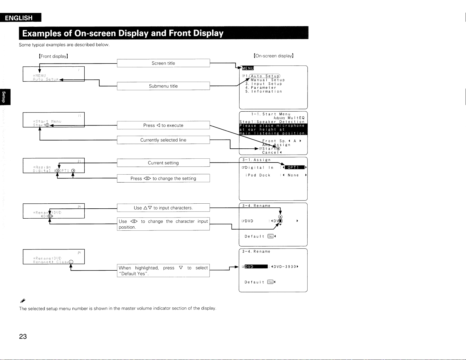
Examples
of
On-screen Display and Front Display
Some typical examples are described below.
[Front display]
Screen title
Submenu title
Press <] to execute
Currently selected line
Current setting
Press <][> to change the setting
[On~screen
IT
1.(
Aut0Set
.
ManuaISetup
Input
Parameter
Information
3-1.Assign
ITD
i g
ita
I
iPod
Dock
display]
u p)
Setup
In:~.
:~None
liI'.~
Use f::,\lto input characters.
'---------------1
Use <][> to change the character input ---,
position.
L-
The
selected setup menu numberisshowninthe master volume indicator section of the display.
--1 When highlighted. press
..
Default Yes".
\l
to select
23
3-4.
Rename
ITDVD
De
f
au
I t
~~
3-4
Rename
..I
Default
~~
Page 27
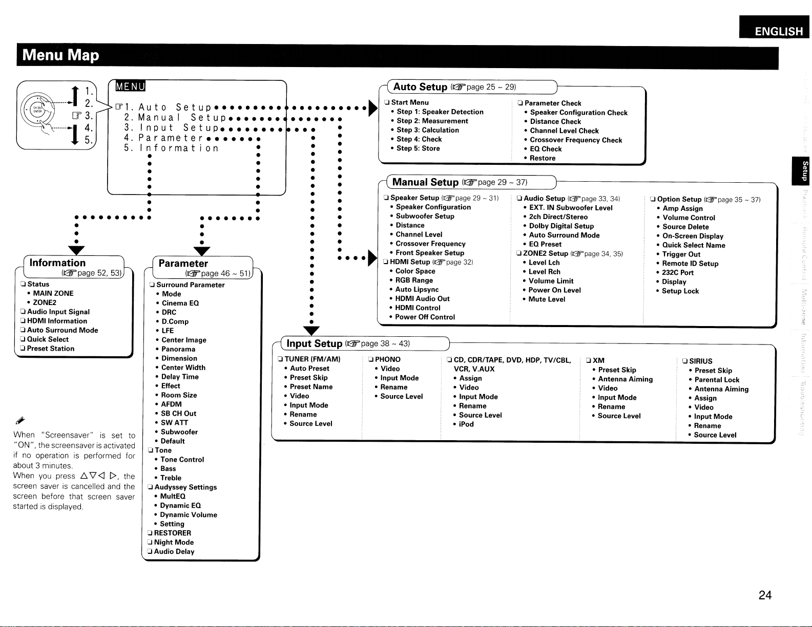
Menu Map
.
~~
~
······-1
-T~:
[?
3.
~:
ITl.
2.
3.
4.
5.
•• •• •• ••
•
•
•
a
Status
•
MAIN
ZONE
• ZONE2
a
Audio
Input
Signal
Information
a HOMI
a
Auto
Surround
a Quick Select
a Preset
When "Screensaver"isset to
"ON". the screensaver
if
no
operationisperformed for
about 3 minutes.
When
you
screen saver
screen before that screen saver
started
is
Station
press
is
cancelled
displayed.
Mode
6.
is
V'
<l
activated
l>,
the
and
the
Auto
Manua
Input
Parameter
Setup
I
Setup
Setup
•••••••••
•••••••
••••••••
•••••••
Information
• •
• •
•
• •
• •
•
•
• •
a
Surround
Mode
•
• Cinema
·DRC
·D.Comp
•
LFE
• Center Image
• Panorama
• Dimension
• Center
• Delay
• Effect
• Room Size
• AFDM
SBCHOut
•
•
SWATT
•
Subwoofer
• Default
aTone
• Tone
• Bass
• Treble
a Audyssey
•
MultEQ
• Dynamic
• Dynamic
•
Setting
a
RESTORER
[J
Night
a
Audio
•• •• •• • •
•
•
•
Parameter
EQ
Width
Time
Control
Settings
EQ
Volume
Mode
Delay
•
•
•
•
..........
•• ••••
••
•••
aTUNER
(FM/AM)
•
Auto
Preset
• Preset Skip
• Preset Name
• Video
•
Input
Mode
• Rename
• Source Level
Auto
a
Start
~
Menu
•
Step':
• Step 2: Measurement
3:
• Step
• Step
4:
5:
• Step
Manual Setup
a Speaker Setup
• Speaker Configuration
Subwoofer
•
• Distance
• Channel Level
• Crossover Frequency
• Front Speaker Setup
a HDMI Setup
• Color Space
•
RGB
Range
Auto
Lipsync
•
• HDMI Audio
• HDMI Control
• Power
OPHONO
• Video
Input
Mode
•
• Rename
• Source Level
Setup
Off Control
((Fpage25-
Speaker Detection
Calculation
Check
Store
((Fpage
!&page29-
Setup
(&page
32)
Out
a
CD,
CDR/TAPE, DVD,
VCR, V.AUX
• Assign
• Video
Input
•
• Rename
• Source Level
• iPod
311
Mode
29)
a Parameter Check
• Speaker Configuration Check
• Distance Check
• Channel Level Check
• Crossover Frequency Check
•
EQ
Check
• Restore
29 -
37)
a Audio Setup (l2Fpage
• EXT. IN
• 2ch Direct/Stereo
•
•
•EQPreset
a ZONE2 Setup
• Level Lch
• Level
•
•
•
Dolby
Auto
Volume
Power
Mute
HOP,
Subwoofer
Digital
Surround
Rch
Limit
On Level
Level
TV/CBL,
Setup
Mode
I&page
OXM
33,
341
Level
34,
35)
• Preset Skip
• Antenna
•
•
• Rename
• Source Level
Video
Input
Aiming
Mode
Option
a
Setup (l2Fpage 35 -
•
Amp
Assign
Volume
232C
Control
Out
Port
a SIRIUS
• Preset Skip
• Parental Lock
• Antenna
• Assign
• Video
Input
•
• Rename
• Source Level
•
• Source Delete
• On-Screen Display
• Quick Select Name
• Trigger
• Remote10Setup
•
• Display
• Setup Lock
Aiming
Mode
ENGLISH
I
37)
s.
24
Page 28

ENGLISH
I
Auto
&Symbols used
Button locatedonboth the main unit and the remote control
unit ..
Button onlyonthe main unit •
Button only on the remote control unit ..
Setup
to
indicate buttons in this manual
MASTER
BUTTON
<BUTTON>
[BUTTON)
VOLUME
/:::,.
to
L.,------,.-j-Fci=i::
<SPEAKERS>
[Front)
RETURN
ENTER,
<I
• Audyssey MultEO® automatically measures the acoustical problems
in
the listening environment to create the best audio experience for
your home theater.
• Audyssey MultEO optimizes a large listening
more listeners
Measurements
(DM-A409) successively at multiple positions throughout the
listening areaasshowninExample U).
recommended to measure 6 positionssothat the measurements
\l
have the proper spatial weighting.
Even
if the listening environmentissmallasshowninExample
measuring at multiple points throughout the listening environment
results in more effective correction.
(-:Measuring positions)
~""lEJ!G]'
~.
are
are
Example
OM
__
.-
seated.
performed by placing the calibrated microphone
U)
......
/~
..
~
...
i.
area
where one or
For
best results, itisstrongly
Example
.........
:,.
: J];ll :
0
- .
"\
/!
Preparations
Connect the included calibrated setup microphone to
1
0,
2
SETUP
the
The
auto setup screen appears automatically.
Sound
--====:::!:f1
receptor
Placethe microphoneat earheighton a tripod orstand
with the microphone pointing directly up towards the
ceiling.
MIC
jack on the main unit.
o
000
!-----4;,.....----,,...J
..
-~--..."
I
=--====
[Rear)
25
About the main listening position
The main listening position refers to the most central position where
one would normally sit within the listening environment.
MultEO uses the measurements from this position to calculate
speaker distance, level, polarity,
for the subwoofer.
To
make manual adjustments to the settings, see pages 29 -
and
the optimum crossover value
(*Ml
31.
*Do not hold the microphone
Be
sure that the path from microphone to the speakers is not
blocked by objects. Avoid placing the microphone close to a seat
backorwallassound reflections may give inaccurate results.
When using a subwoofer, make the following settings before starting
the auto setup procedure:
• Defeat the volume and crossover controls if possible
•
If
thisisnot possible then set
· Volume: "12 o'clock" position
· Crossover frequency: "Maximum/Highest Frequency"
·
Low
pass filter:
· Standby mode:
"Off"
"Off"
in
your hand during measurements.
Page 29

'N·O.
•Donot disconnect the setup microphone until the auto setup
procedure
• When using headphones, unplug the headphones before starting
the auto setup procedure.
Auto Setup
Optimize settings for speakersinuse.
o
The settings found at this stage are applied automatically.
( Step
is
completed.
Auto
Setup
1:
Speaker Detection
[Auto setup flow]
)
t
2:
( Step
Measurement
)
t
3:
( Step
( Step
( Step
Calculation
4:
Check
5:
Store
)
t
)
t
)
'Nti
••
• Loud test sounds maybeplayed during Audyssey MultEO automatic
speaker setup. This
noise
in
room, these test signals will increaseinvolume.
Do
not stand between the speakers and setup microphone or allow
•
obstacles
will cause inaccurate readings.
• Make the room
the room measurements. Close windows, silence cell phones,
televisions, radios, air conditioners, fluorescent lights, home
appliances, light dimmers, or other devices
be
Cell
the measurement process
may cause measurement disruptions (even if the cell phoneisnot
use).
• Operating
the measurements
in
affected by these sounds.
phones shouldbeplaced away from
MASTER
is
part of normal operation. If thereisbackground
the path while the measurements are being made. This
as
quietaspossible. Background noise
as
measurements may
all
as
VOLUME
Radio Frequency Interference
during the measurements will cancel
audio electronics during
can
disrupt
(RFI)
About the Auto Setup
The Audyssey MultEO auto setup function detects the presence of
and
each speaker
level, distance,
MultEO corrects acoustical distortions within the listening area.
Before starting, connect
Once started, MultEO will
speaker.
If
an
error message appears during the measurements,
Messages", take the advised action, then start the measurements
again
(D:2Fpage
Front Speaker
The front speaker tobemeasured
here.
[Selectable items]
o :Output test tone from front speakers
B : Output test tone from front speakers
A+B
:Output test tone from front speakers A and
automatically calculates the speaker
and
optimal crossover frequency setting. Audyssey
and
position
all
playa
28).
of your speakers.
series of test tones through
canbeselected ahead of time
A.
B.
B.
size,
check"
channel
each
Error
( Step 1 : Speaker Detection
• Menu screen •
CD
Auto
Setup
AudysseyMuI
Fro
n t Sp.
Center
Su
[fNext~
<I.
<I.
bwo0fer
Sur
r 0 u n d S
S.
Ba c k Sp .
Ret
r y
Retry
~
.....
Front
Sp.~A
Amp
Assign
[fStart~
Cancel
~
in
The speaker connection and polarity are detected at the first
measurement position (main listening position). The following
attributes are also determined at this time: "Speaker Size", "Speaker
Distance", "Channel Level", "Crossover Frequency".
CD
Press
6.
(1)
• If the result differs from the actual connection status oranerror
message appears, use
press
• If the result still differs from the actual connection status after
measurement or the error message still appears, itispossible that
the speakers are not connected properly. Turn the AVR-2309CI
off, check the speaker connections and repeat the measurement
process from the beginning.
V to select "Start
Press6.to
•Tocancel the measurements, press
select "Next
<I
to repeat the measurement.
~
.....
.....
", then press
\l
to on-screen
", then press
<I.
display"
'n·O.
Do not change the speaker connections or subwoofer volume after
"Step 1".
ENGLISH
tEQ
Sp.
p.
1spkr
"
and
Yes
Yes
Yes
Yes
then
re-
)
I
DAmp
Advanced
For details, refer to
Assign
setting:
changes power amplifier assignment.
"Amp
Assign"
(D:2Fpage
35).
26
Page 30

ENGLISH
C'-S_t_e:..p_2_:_M_e_a_s_u_re_m_en_t
• Menu screen • •
o 0
J
)
(Step
Menu
3 : Calculation
screen •
)
(Step
•
Menu
4 : Check
screen •
)
o
I]'Next~
Calculate.
Cancel~
ITNext~
Calculate.
Ret
r y
~
Cancel.
CD
Press
Do.
to select
• The measurement of the 2nd position starts.
® Move the microphone
• The measurementofthe 3rd position starts.
Q)
Perform @ repeatedly for the 4th, 5th, and 6th measurments.
• "All the measurements were finished." is displayed
screen display. When you have completed measurements
positions.
you
want to stop after measuring just five or fewer positions,
• If
\l
press
After completing a measurement position, move the microphone to
the next position.
Measure at 6 positions: the main listening position
surrounding positions. Although it
positions, it
is
"Next
<OIl",
then press
to
the 3rd position and press
to select "Cancel
recommended to measure 6 for best results.
<011",
is
.a.,.•"
ITCancel.
<l.
<l.
on
the on-
in
then press
allowable to measure less than 6
<l.
and
5 other
ITCaleuIate
Ret
Cancel
The values obtained from the measurements are automatically
analyzed and the attributes for each of the speakers
area
are determined.
CD
Press
Do.
• Analysis begins.
• Analysis takes several minutes to complete.
• The time required for this analysis depends
speakers connected. The greater the numberof speakers connected,
the longer analysis will take.
to select "Calculate
r y •
~
~
<011",
..
!---------_
then press
__
_-
in
<l.
on
the number of
the listening
-N·Ua
•Donot change the speaker connections or subwoofer volume,
or speaker locations after making measurements. If changes are
6
necessary, make the changes and use the Audyssey MultEO auto
setup once again for
•
For
instance, if the location or direction of a speakerisaltered, the
Auto Setup should
solution for the
an
updatedEOsolution.
be
performed again to ensure the correct
new
room configuration.
ITSpeaker
Distance
Channel
Crossover
When analysisiscomplete, check the analysis results for the following
four items.
CD
Make your selection using
• Presence and size of speaker
"Speaker Config. Check"
• Distance
"Distance Check"
• Speaker channel level
"Channel Level Check"
• Crossover Frequency
"Crossover
@ Use
oTo switch
Press
This returns you to analysis results items,sorepeat step
OTo
Press
EO
Distance values that
be
may
Thisisbecause these filters add electrical delay (distance) to the signal
is
that
of
speaker from listening position
Freq.
Do.
\l
to
RETURN
Check"
change which speakerisdisplayed.
to
another analysis result item
.
proceedto"Step5:Store"
Do.
to select "Next
accurate for speakers with built-in filters (subwoofers,
compensated forbythe Auto Setup process.
are
Config.
Level
N
ext
£::,.
\l
<OIl",
then press
greater than the actual distance of a speaker
Check
Freq.
~
and
Check
Check
Check
press
ENTER.
<l.
CD.
etc)
27
Page 31

ENGLISH
(Step
• Menu
5 :Store
screen.
CD
IJStore~
Cancel~
The auto setup measurement results are storedinthe AVR-2309CI.
CD
Press
b..
to
select"
• "Storing Please wait···"isdisplayedonthe on-screen display
while the results
• When storing
finished."isdisplayedonthe on-screen display.
(1)
Select
CID
"Exit",
Disconnect the setup microphone from the AVR-2309CI.
Store"''',
are
is
complete, "Storing complete. Auto Setupisnow
then press
then press
being stored.
<J.
<J
.
OTo cancel storing
Press
b..
\l
to
select"
• All the measured auto setup data will be erased.
Cancel "''', then press
<J.
-N·na
Do not turn the
power
off while the settings are being stored.
)
Error Messages
If the auto setup procedure could notbecompleted due to speaker installation, the measuring environment, etc.,anerror message
displayed. If this happens, check the relevant items, be sure to take the necessary measures, then perform the auto setup procedure over
again.
Error messages (examples)
Ret
r y
~
Cancel~
Auto
Setup
=.
;::=~=
~
§
E7
~_
••
IJ~Front
MuItEQ
',U
.;_~""'4
Ret
r y
~
r=~=
\:l
§
Cancel
Auto
Setup
=.Mul
G::_""U
E7
IJ~Front
~
Cause
• Included setup microphoneisnot connected. • Connect the included setup microphone to the
MIC
all
speakers couldbedetected. • Check the speaker connections.
• Not
• The front L speaker was not properly
detected.
• Too much noise
measurements to be made.
• Speaker or subwoofer sound
accurate measurements to be made.
• Displayed speaker could not be detected. • Check the connections of the displayed speaker.
· The front R speaker were not properly
detected.
· Only one channel of the surround speakers
was detected.
Sound was output from the R channel
when only one surround back speaker was
connected.
· The surround back, but the surround speaker
was not detected.
• Displayed speaker connected with
tEQ
polarities reversed.
in
the room for
accurate • Either turn off any device generating noise or move it
low for • Check the speaker installation and the direction
is
too
the • Check the polarities of the displayed speaker.
jackonthe main unit.
away.
•
Try
again when the surroundings
which the speakers
• Adjust the subwoofer's volume.
For
some speakers, this error message may
•
displayed even if the speakerisproperly connected. If
are
sure that the wiringiscorrect, select "Skip".
you
Measures
are
facing.
are
quieter.
is
SETUP
I
in
be
, Select
-n.na
Ret
r y
~
Cancel
Skip~
"Retry"
Be
sure to turn the power off before checking the speaker connections.
~
to measure again.
28
Page 32

ENGLISH
II
Check auto setup measurement results.
This is displayed after the auto setup procedure
Parameter Check
is
completed.
Manual
Setup
[Selectable
Speaker
Channel
The auto setup results
Config.
EO
items]
Level
Check
Check
Check
Distance
Crossover
canbeset
again
Check
Freq.
when"
Check
Restore"isselected.
Make detail settings for various parameters.
II
Symbols
Button locatedonboth the main unit and the remote control
unit
Button onlyonthe main unit
Button onlyonthe remote control unit
SOURCE
used
SELECT
to indicate buttonsinthis manual
~
BUTTON
~
<BUlTON>
~
[BUlTON]
<DIMMER>
Speaker Setup
Use
thiS
change the settings made
•
procedure to set the speakers manually or If you wish to
Menu
screen •
1.
Auto
en.
ManuaISetup
3.
Input
4.
Parameter
5.
Information
Or
'-r-------T---j-F-i:
<SPEAKERS>
[Front]
<MENU>
<J[>
oSpeaker Configuration
Select speaker configuration and size.
(bass reproduction capability)
Front Speaker
Select front speaker size.
[Selectable items] I
Setup
Setup
with
the auto setup procedure.
1
2.Manual
0"1.
LargeISmall
Speaker
2.
HOMI
3.Audio
4.
ZONE2
5.0ption
Setup
Setup
Setup
Setup
Setup
Setup
29
IFor details on
[Rear]
howtoselect, set and cancel settings for each
menu,
see
[0-06: I
:000
io
0'0:-
LO_o:6!
"0'
----.--._,
l<2__.
o I
"Menu
i
SOURCE
SELECT
[A.
MENU]
I
__
~
<H>
[TEST]
Operations" (l(W'page 22).
Center Speaker
Select center speaker use and size.
[Selectable items]
Subwoofer
Select subwoofer use.
[Selectable items]
LargeISmallINone
~
No
Page 33

ENGLISH
Surround Speaker
Select surround speakers use
[Selectable items]
Large
and
I
Small
size.
I
None
Surround Back Speaker
Select surround
[Selectable items] (
back
speaker
Large
([2spkrs
use
and
I
Small
I 1
spkr
size.
I
)
None
)
-N·na
By
default. the AVR-2309CI's "Amp Assign" settingissetto"ZONE2".
To
useasthe surround
"Amp Assign" setting
Large
:Select this when using large speakers with ample low
frequency reproduction capabilities
Small
:Select this when using small speakers without ample low
frequency reproduction capabilities.
None
:Select this whennospeakerisconnected.
Yes
:Select this when a subwoofer
No
:Select this whennosubwooferisconnected.
2spkrs
Select the number of surround
1spkr
back
speaker for the MAIN
((Fpage
35).
back
is
connected.
speakers.
ZONE,
change the
#
- Select "Large"or"Small" not according to the physical
speaker but according to the low frequency reproduction capabilities
on
based
31)
- When "Front Speaker"isset to "Small", "Subwoofer"
automatically set to "Yes".
-If
to "Large".
-If
are
- When "Front Speaker"
be
- When using just one surround back speaker, connect it to the left
channel (SBl).
the frequency set at "Crossover Frequency"
"Subwoofer"issetto"No",
"Surround Speaker"isset to "None", "Surround
automatically set to "None".
set to "Large".
"Front Speaker"isautomatically set
is
set to "Small", "Center Speaker"
Back
size
of the
((Fpage
Speaker"
can
can
not
Subwoofer Setup
low
range
signal tobereproduced by subwoofer.
[Selectable items]
LFE
I:
Play
low
range
and
LFE
"Small".
LFE+Main
:
Play
low
range
and
LFE
#
- This
canbeset when menu "Speaker Configuration" - "Subwoofer"
is
set to "Yes".
-
Play
music or a movie source
strongest
- Select "LFE+Main" if
produced from
bass.
the
subwoofer.
you
want the
signal of channels set to
signal of
and
all
channels
select the mode offering the
bass
signals to always
IJOistance
Set distance from listening position to speakers.
Before making the settings, measure the distance from the
listening position to the different speakers.
Feet I Meters
Select unit for distance.
Step
Select step. (smallest distance)
[Selectable items]
[J!!:J
~
O,1ft
.
Canbeselected when "Feet"isset.
0.01m
:
Canbeselected when
"Meters"isset.
Default
Resets the settings to the default values.
Distance measurement
Select the speaker
Set the value closest to the measured distance.
[Variable range]
O.Oft-6O.Oft
O.OOm
-18.00m
you
want to set. then set the distance.
:Display when "Feet"
is
set.
:Display when "Meters" is set.
-U'Ua
Set the distance between the listening position
be
speakers to
no
more than 20.0ft(6.00 meters).
and
I
the various
For details on
howtoselect, set and cancel settings for each menu, see
"Menu
Operations"
(Gf'page
221.1
'J
30
Page 34

ENGLISH
Channel Level
djust channel levelstoobtain equal volume from
Test Tone
Select test tone playback method.
[Selectable items]
I
Auto
I:
Automatically switch speaker from which test tone
output.
Manual
Test Tone Start
Output test tone.
[Variable range]
*
Default
Resets the settings to the default values.
~
Adjusting with the main remote control unit using the test tones
only possibleinthe
mode.
stored
[Adjusting using
CD
o Use
G)
:Manually switch speaker from which test tone
OFF
*
-12dB
In
the
case
dB" will change the setting to "OFF" (none).
Press
Test tones
When the adjustments
of asub woofer, reducing the volume when itisat
Operating from
The
in
the memory.
"Auto"
adjusted levels for the different modes
test
the
mode and only effectiveinthe STANDARD
tones]
[TESn.
are
<l
output from the various speakers.
C>
to adjust so that the volumeisequal for
are
completed, press
- I
OdB
main remote control unit
I -
[TESn
all
speakers.
is
+12dB
are
automatically
all
speakers.
again.
output.
"-12
II
Crossover Frequency
Select crossover frequency from which subwoofer handles low
range signal.
[Selectable items]
40Hz
60Hz
180Hz
190Hz
200Hz
Only the portion of the bass sound of the various speakers output
is
from the subwoofer that
here
Set this according to the
the speakers you
is
output.
250Hz
are
has
low
using.
100Hz 110Hz
a frequency below the frequency set
frequency reproduction capabilities of
120Hz 150Hz
Advanced
Set the crossover frequency separately for the different speakers.
o If
in
the "Advanced" settings, "Subwoofer Setup" (Gr'page
in
the menuisset to "LFE", itispossible to make this setting
for speakers set to "Small" at "Speaker Configuration". If set to
"LFE+Main", this setting
size.
o
For
speakers set to "Small", sound below the crossover frequency
is
cut from the sound output. The cut bass soundisoutput from the
subwoofer or front speakers.
is
o Always set the crossover frequency to
speakers, however,
to a higher frequency.
canbemade regardless of the speaker
"80
we
recommend setting the crossover frequency
Hz". When using small
II
Front Speaker Setup
Select front speakers to use for each surround mode.
[Selectable items]
I
Normal
Custom
When set to "Custom", you
to use for each surround mode.
[Selectable items]
DIRECT/STEREO:
I·
To
change the settings, select
Make separate settings for 2-channel mode.
MULTICH:
-N·n.
When set to "Custom",
30)
IT]
IT]
<SPEAKERS>
"Custom".
can
select beforehand the front speaker
B
A+B
B
A+B
does not operate.
o When the menu "Speaker Configuration" - "Surround Back
Speaker" setting
speaker display
o Speakers set to "None"
not displayed.
o When "Channel Level"
the surround modes.Toadjust the channel level separately for the
different surround modes, use the operation see page
31
(Gr'page
is
set to "Surround
is
1 For details on
30)isset to"1spkr". the surround back
Back
in
the "Speaker Configuration" settings are
adjusted, the adjusted values
howtoselect, set and cancel settings for each menu, see
Sp." .
63.
are
set for
all
"Menu
Operations" (U2ff'page 22).
Page 35

HDMI Setup
Make settings for HOMI video/audio output
•
Menu
screen •
2.
['"2.
1.
3
4.
5.
Manua I
Audio
ODtion
SDeaker
HOMI
ZONE2
Set
uD
SetuD
SetuD
SetuD
Set
uD •
Set
uD
1
2-2.
HOMI
ITColor
RGB
Auto
looJ
2-2.
HOMI
00
HOMIAud i 0
HDMI
Power
Range
SetuD
SDace
YCbCr
Normal
•
LmSynC
• c
Set
•
AMP
Control
tml.
:.OF F
Off
: .OFF
tml·
.OFF
uD
Out
•
Con t r 0 I
ENGLISH
II
fJRGB
Make settings for
[Selectable items]
I
Normal
Enhanced
Range
RGB
output range.
I:
Use
video range from16(black)
:Video
range
from 0
setting to avoid black washout.
(black)to255
to 235 (white).
(white).
Use
this
•
•
When "YCbCr"
have
no
IJ
Auto Lipsync
Automatic compensation for timing shiftinaudio
output.
[Selectable items]
effect.
is
selected under "Color Space", "RGB Range" will
~
OFF
and
video
Power Off Control
Interlock power
[Selectable items]
• This
canbeset when "HDMI Control"issetto"ON".
•
Please
consult the operating instructions for
to check the settings.
_¢("
••
• When the "HOMI Control" setting
off the power to the connecting devices afterwards
back
on.
•
The
"HOMI Control"
the power to the equipment
For
details,
•
OFF
with HOMI control.
~
and
see
"HOMI Control Function" ((W'page
OFF
has
"Power Off Control" does not work when
is
off.
each
been changed, always turn
connected device
and
then turn
62).
I
D Color Space
Make settings for output color space.
[Selectable items]
YCbCr
RGB
When connected to a monitor with a
compatible) usinganHOMI/OVI converter cable, the signals are output
in
RGB
:Output using
:Output using
format, regardless of this setting.
YCbCr
RGB
format.
format.
OVI-O
connector
(HOCP
II
HOMI Audio
Select HOMI audio output device.
[Selectable items]
I
AMP
I:
Use speakers connected to receiver for audio playback.
TV:Use
speakers ofTVfor audio playback.
Out
_M·ha
When the HOMI control functionisoperating, the setting of audio
playback
Control Function").
[Selectable items]
Please
to check the settings
in
the connectedTVtakes priority (i2if'page62"HDMI
II
HOMI Control
Make settings for
consult the operating instructions for
HOM
I control function.
ON
~
each
connected device
-M·jja
For
details, see "HOMI Control Function" (GFpage
For details on
howtoselect, set and cancel settings for each menu, see
62).
"Menu
Operations" (@"'page
22)·1
32
Page 36

ENGLISH
Audio Setup
Make settings for audio playback
•
Menu
screen •
2.
ManuaISetup
1.
Speaker
2.
HDMI
IT3.
Aud
4. ZONE2
5.0ption
Setup
Setup
i 0
Setup
Setup
Setup
2-3.Audio
IT1.EXT.
2.
2ch
3.Dolby
4.
Auto
5. EQ
I N
Direct/Stereo
Surround
Preset
D EXT. IN Subwoofer Level
Set the subwoofer level for playback.
OdB
+5dB
[Selectable items]
We
recommend setting to"+15dB".
fl2ch
Make speaker settings for 2-channel mode playback.
Direct/Stereo
+10dBI+15dB
Setup
SW
Digital
Level
Setup
Mode
Front
Select front speaker size.
[Selectable items]
I
LargeISmall
:Select front speaker
size.
Subwoofer
Select subwoofer use.
[Selectable items]
~
Subwoofer
Select low range signal tobereproduced by subwoofer.
No
:Select subwoofer use.
Mode
II
Dolby Digital Setup
Set dynamic range for downmix playback of Dolby Digital
sources.
[Selectable items]
ON
Compressionisused. Select this if sound from front
speakers
~:
• Set this to
distorted .
• When not using the center speaker or surround speakers, the
playback sound
Do
setting.
is
distorted.
not use compression. Thisisthe recommended
"ON"
if the sound from the front speakers seems
is
down-mixed
and
output from the front speakers.
[Selectable items]
~
I
Crossover
Select crossover frequency from which subwoofer handles low range
signal.
[Selectable items]
40Hz
200Hz
LFE+Main
60Hz
250Hz
:Select subwoofer signal
180Hz 190Hz
:Select crossover frequency.
100Hz 110Hz
120Hz 150Hz
II
Auto Surround Mode
Make setting for memorizing surround mode setting for each
input signal type.
[Selectable items]
~:
Memorize settings. Most recently stored surround mode
automatically selected.
Do
OFF
not memorize settings. Surround mode does not change
according to input signal.
is
Setting
To
change the settings, select "Custom".
[Selectable items]
I
Basic
I:
Use the same settingsasin
Custom
33
: Make separate settings for 2-channel mode.
I For details on
howtoselect, set and cancel settings for each menu, see
"Speaker Setup".
Distance
Set distance from listening position to front left speaker.
[Variable range]
Distance
Set distance from listening position to front right speaker.
[Variable range]
FL
O.Oft-6O.Oft
FR
O.Oft-6O.Oft
-N'U-
Set the distance between the listening position and the various
speakers to no more than 20.0
ft
"Menu
(6.00 meters).
Operations" (D2Fpage 22).
•
The
auto surround mode function lets
surround mode last used for playing the four types of Input signals
listed below.
CD
Analog
and
PCM
(1)
Dolby Digital
CIl
Dolby Digital
2-channel signals
and
DTS
2-channel signals
and
DTS
multi-channel signals
® Multi-channel signals other than Dolby Digital
etc.)
• When playing
not change even if the input signal
in
the
PURE
DIRECT
you
storeinthe memory the
and
DTS
(PCM,
mode, the surround mode does
is
changed.
Page 37

ENGLISH
II
EQ Preset
Set MultEO related settings and ManualEObeforehand.
EQ
Customize
When MultEO®
canbeskipped when selectedonthe main unit or remote control
unit.
and
ManualEOyou are not using
are
preset
MultiEO
o Before running Auto Setup
[Selectable items]
Manual: I
UsedINot
Used
o After running Auto Setup
[Selectable items]
Audyssey Byp. UR
Audyssey Flat : I
Direct
Mode
Select
"MultEO"
[Selectable items]
ON
Use
~:
Do
:1
r-
Manual : I
use for DIRECT or
"MultEO".
not use
"MultEO".
-Us-e-dUsed
Used
Not
Not
Not
PURE
Used
Used
Used
DIRECT mode.
Manual
Adjust tonal quality for
EQ
each
speaker using graphic equalizer.
o Default
Resets the settings to the default values.
o
Base
Curve Copy
Copy the MultEOIIAudyssey Flat" correction curve.
[Selectable items]
Yes
II
Base Curve Copy"isdisplayed after the auto setup procedure
been performed.
o Adjust
CD
Select speaker adjustment method.
[Selectable items]
EachCH:Adjust tonal quality for each speaker separately.
UR
All
@ Select the speaker
[Selectable items]
[Variable range]
No
CH
CH
:Adjust tonal quality for each
CH
:Adjust tonal quality for
and
frequency band and adjust the level.
63Hz
2kHz
-20dB
LIR
all
speakers together.
125Hz
250Hz
4kHz
8kHz
- I
OdB
I -
speaker
500Hz
16kHz
+6dB
pair.
1kHz
ZONE2 Setup
Make settings for
• Menu screen •
2.Manual
1.
2. HOMI
3.Audio
Cf4. ZONE2
5.0ption
has
Speaker
Setup
Setup
Setup
Setup
audiO
playback In a ZONE2 system.
Setup
Setup
2-4.
CfL
ZONE2
eve
I L c h :~0
Rc h :~0
Vol.Limit
Power
On
Mute
Lev.
-N·na
"ZONE2 Setup"isdisplayed when ZONE2isselected with
Assign" ((W'page
oLevel
Adjust the left channel output level.
[Variable range]
tJ
Level
Adjust the right channel output level.
Lch
Rch
35).
-12dB
- I
OdB
I -
+12dB
Setup
Lev.
:~OFF
:
Last~
:~Ful
dB
~
dB~
~
I~
"Amp
I
For
detailsonhow
[Variable range]
-12dB
- I
OdB
I -
+12dB
to select, set and cancel settings for each menu, see "Menu Operations" ((1f"page
22).\
34
Page 38

ENGLISH
I
II
Volume Limit
Make a setting for maximum volume.
[Selectable items]
~:
-2OdB
-1OdB
OdB
D Power
Define the volume setting thatisactive when the poweristumed
on.
Do
not set a maximum volume.
Set the maximum volume to
Set the maximum volume to -1 0 dB.
Set the maximum volume to 0 dB.
On
Level
-20
dB.
[Selectable items]
Last
I:
Use the memorized setting from the last session.
Always use the mutingoncondition when power
is
tumed
on
[Variable range]
-7OdB-+18dB
Set the volume level when the poweristumed
in
units of 1 dB.
Option Setup
Make vanous other settings
• Menu screen •
2.
ManuaISetup
1.
Speaker
2.
HDMI
3.Audio
4.
ZONE2
Ci"5.0ption
DAmp
Define how the amplifier for the surround back speaker channels
is
used.
The places where the surround back amplifier
freely according to the usage environment. This makes it possible to
output sound to rooms other than the room (the MAIN
surround playbackisperformed (multi-zone playbacklorplay the sound
with high quality using the front speakers (bi-amp connections).
on
[Selectable items]
7.1ch
I ZONElI
Setup
Setup
Setup
Setup
Setup
Assign
FrontA
1
Ci"1.Am
Bi-Amp
2-5.0ption
pAs
2.
Vol.
3.Source
4.0n-Screen
5.
Quick
6.TriggerOut
7.
Remote
8.
232C
9.Display
10.
Setuo
FrontB
s i g n
Control
Select
Por
are
Bi-Amp
Setup
Delete
10
t
Lock
Display
Setup
used
ZONE)
Name
canbeset
where
Volume Control
Volume Limit
Make a setting for maximum volume.
[Selectable items]
~:
-20dB
-10dB
OdB
Power On Level
This sets the volume set when the MAIN ZONE's poweristumed
on.
[Selectable items]
[Variable range]
-BOdB-+18dB
Do not set a maximum volume.
Set the maximum volume to
Set the maximum volume to
Set the maximum volume to 0 dB.
Last
I·
Use the memorized setting from the last session.
Always use the mutingoncondition when power
is
tumed
on.
Set the volume level when the poweristumed on
in
unitsof1 dB.
-20
-10
dB.
dB.
mMute
Set the amountofattenuation when mutingison
Level
[Selectable items]
~:
--40dB
-20dB
35 For details on
The
soundiscut off entirely.
:
The
soundisattenuated by 40 dB.
The
soundisattenuated by 20 dB.
howtoselect, set and cancel settings for each menu, see "Menu Operations"
Mute
For
details,
see"
..
(n::r
page 69 - 72).
AmpAssign/ Multi-zoneConnections
and
Operations"
Level
This sets the amount of attenuation of the volume when the mute
modeissetinthe MAIN ZONE.
[Selectable items]
(&page
~:
--40dB
-20dB
22).
The soundiscut off entirely.
The soundisattenuated by 40 dB.
The soundisattenuated
by
20 dB.
Page 39

ENGLISH
II
Source Delete
Remove input sources that are
[Selectable items]
ON
I:
Use this source.
Delete
: Do
not
use this source.
not
used from the display.
Default
Resets the settingstothe default values.
-N·n=-
• Input sources being usedinthe various zones cannot be deleted.
• Input sources set
SELECT.
DOn-Screen Display
Make on-screen display related settings.
Screensaver
Make screensaver settings.
Use the screensaver
setto"ON",
When
for about
[Selectable items]
Text
Input source and
[Selectable items]
I
3 minutes.
ON
:Activate the screensaver if there
minutes.
OFF
:Turn the screensaver function off.
ON
I:
Turn display on.
OFF
:Turn display off.
to
"Delete"
to
prevent burn-inonthe monitor screen.
the screensaverisactivated if thereisno activity
mode
display.
cannot be selected using
is
no activity for about 3
SOURCE
Master Volume
Master volume display during adjustment.
[Selectable items]
I
ON
I:
Turn display on.
OFF
:Turn display off.
Tuner Information
This sets the
operation
[Selectable items]
Always
I
30sec
10sec
OFF
time
is
I:
the on-screen display is displayed
performed.
Show display continuously.
Show
display for 30 seconds after operation.
Show
display
for
10 seconds after operation.
: Turn display off.
iPod Information
This sets the
operationisperformed.
[Selectable items]
Always
I
30sec
10sec
OFF
time
the on-screen display is displayed
Show
display continuously.
I:
Show
display
:
Show
display
: Turn display off.
for
30 seconds after operation.
for
10 seconds after operation.
Display Mode
Select the on-screen display's display mode.
[Selectable items]
I
Mode1
I:
If thereisno video signal, flickeringofthe on-screen
display is not prevented.
Mode2
:Prevents flickering
no video signal.
Use this mode if the on-screen display does not appear
in
the
Mode1,as
used.
of
the on-screen display
may happen accordingtotheTVbeing
II
Quick Select
Change the Quick Select name.
to
16 characters can be input.
Up
[Input characters]
A..Z a..z 0..9 !# %
Default
when
a tuner
Resets the settingstothe default values.
II
Trigger
Select the conditions to turn on the trigger
the zone, input source, surround mode, etc. For details about
trigger
out
Out
function, see page 20.
Selecting the Zone
Select the zone for
whenaniPod [Selectable items]
Setting with Respect to the Input Source
When the input source set toonis
[Selectable items]
ON
Activate trigger on this mode.
Do not activate trigger
Setting with Respecttothe Surround Mode
• When the surround
on.
when
there
• Associated
• This
Zone".
• Associated when
is
the Input Source"
[Selectable items]
ON
with
can
respecttosurround modes that are set to
be set if the
an
: Activate trigger
: Do not activate trigger on this mode.
Name
&.
()
*
+,
-./:;
="?
out
which
the trigger
All
mode
set to onisselected, the trigger out turns
"MAIN
input source for which "Setting
is
setto"ON"isselected.
on
outisset.
MAIN
on
ZONE"isselected at "Selecting the
this mode.
ZONE2
selected, the trigger
this mode.
@
[\]
with
with
(space)
respect
out
turns on.
"ON".
Respect to
I
to
the
For details on
howtoselect, set and cancel settings for each menu, see "Menu Operations" (iGT'page
22).1
36
Page 40

ENGLISH
Default
Resets the settings to the default values.
Remote10Setup
ID.
[Selectable items]
_~[.ija
When using
control unit (RC-1099), use Remote10"1" (default).
When using a separately sold remote control unit (RC-7000CI, etc.).
this function
unit and the receiver.
II
Set when external controller or 2-way remote control unit
connected.
[Selectable items]
I
Serial
2WayRemote
canbeused. Match theIDsetting of the remote control
232C Port
Control
IT]
the
AVR-2309CI
I:
Set when usinganexternal controller.
Set when using a 2-way remote control unit.
2
with
only
3
the
included remote
4
is
-N·ija
When using a 2-way remote control unit (RC-7000CI and
sold separately). set this to "2Way Remote".
RC-7001
RCI,
1I0ispiay
Adjust display brightness of the receiver.
[Selectable items]
I
Bright
I:
Normal display brightness.
Dim
Dark
~
Press
When setting to "OFF", the display brightness of the menu setting
operation changes to "Dark".
Reduced display brightness.
. Very
low
display brightness.
OFF
Displayisoff
unless controls are operated.
Operating from the main unit
<DIMMER>
~
~
Bright - Dim
OFF
- Dark -----.J
---r
1m
Setup
Protect settings from inadvertent change.
[Selectable items]
ON
~
Lock
:Turn protection
:Turn protection off.
on.
#'
-When
"Setup Lock"isset to
no longerbechanged. Also, "SETUP LOCKEDI"isdisplayed if you
attempt
to
RESTORER
Night Mode
Parameter
MultEO
Dynamic
Dynamic Volume
Channel Level
. Audio Delay
in
To
"Setup Lock" screen, then change the setting to "OFF".
operate related buttons.
EO
cancel the setting, press
"ON",
the settings listed below
<MENU>or[A.MENU]
to re-display the
can
37 IFor details on
howtoselect. set and cancel settings for each menu, see
"Menu
Operations"
IGT'page
22),
Page 41

ENGLISH
Input
II
Symbols usedtoindicate buttonsinthis manual
Button locatedonboth the main unit
unit •
Button onlyonthe main unit •
Button onlyonthe remote control unit •
Setup
and
VIDEO
the remote control
BUTTON
<BUTTON>
[BUTTON]
SELECT
/:::,.
\l
Use
this procedure to select the input source
related to playing input sources.
o TUNER
This menuisfor "TUNER".
(AM/FM)
• Menu screen •
3.
Input
Se
IT 1.
Auto
2.Preset
3.
4.
5.Input
6.
7.
Prese"!"··········-
PresetName
Video
Mode
Rename
Source
t
OXM
L.,.....--....,!--------.-cl=r;:
<INPUT
[Front]
[Rear]
MODE>
ot---,-I
VIDEO
SELECT
I
'iit
~<,.~_*
~-'
[INPUn
/:::,.
-'
I
ENTER
ENTER.
\l
<H>
<][>
This menuisfor
• Menu screen •
3.
Input
Setup
IT1.Preset
2.
Antenna
3.Video
4.InputMode
5.
Rename
6.
Source
o SIRIUS
This menuisfor "SIRIUS".
• Menu screen •
3.Input
IT 1.
2.
3.
4.Assign
5.Video
6.Input
7.
8.
Preset
Parental
Antenna
Rename
Source
Setup
Mode
tup
Skip
Leve
"XM".
Skip
Aiming
Leve
Skip
Lock
Aimi
Leve
.~
••
IlJ.N.E.B
•
[FM/AM
I
~
I
~
SIRIUS
ng
I
••
TU]'1~" •
XM
'~'l
......
~
and
make the settings
Displayed when
source name
changed with
"Rename':
o PHONO
This menuisfor "PHONO".
• Menu screen •
is
o CD, CDR/TAPE, DVD,
This menuisfor "CD", "CDRfTAPE", "DVD", "HDP", "TV/CBL" ,
"VCR", "V.AUX".
• Menu screen •
*
The
menu settings below
when "iPod dock"
3.Input
Assign
1.
2.
Video
3.
Input
4.
Rename
5.
Source
IT6.
iPod
~----------~
3.
Input
C1'1.Video
2.Input
3.
Rename
4.
Source
~----------~
3.Input
IT1.Assign
2.Video
3.InputMode
4.
Rename
5.
Source
is
set to "Assign"
Setup
~
VCR
Mode
Level
Setup
~
PHONO
Mode
Leve
I
HOP,
TV/CBL, VCR, V.AUX
Setup
~
CD
Level
canbemade for these input sources
~l
3-6
iPod
:
Mode
~
A I I
:
~
OFF
ITRepeat
Shuffie
Mode
I
~
~
For details
on
howtoselect. set and cancel settings for each menu. see "Menu Operations"
(~page
22). 38
Page 42

ENGLISH
Changing the input source within Input Setup
3.
Input
Setup
~_
•.
O"l.Assign
2.Video
3. I
nputMode
4.
Rename
5.
Source
The input source currently selectedinthe MAIN
even when the input source within Input Setupischanged.
SettingsRelated
Level
to
ZONEisnot changed
Playing
Input
Sources
oAuto Preset
Use the auto preset function to program radio stations.
[Input source] I
[Selectable items]
Start
IfanFM station cannotbepreset automatically, select the desired
stationbytuning it in manually, then preset it manually.
Start the auto preset process.
TUNER
I
fJ
Preset Skip
Set the preset memories that you do not want to display when
tuning.
A-G
Select the preset channel(sl you do not
[Input source]
[Selectable items]
~:
Skip
When set to "Skip", itispossible to skip entire preset memory blocks
(AtoG)
II
Preset Name
Assign name to a preset memory.
Names containingupto 8 characters
l!'!~'!J
Display this number.
Skip this number.
IXM,I
want
to display.
~IRIUS
j
can
be input.
A1-G8
Select the preset memory number.
[Input source] i
[Characters
A-Z
a
-z
TUNER
that
can be input]
0-9
!
#%&.
I
()*+.
-
.f:;="?@
[\]
(space)
Video
rce.
Video Select
Switch video input source while listening to audio signal.
[Input source]
[Selectable items]
OVO
HOP
Select video input source to view.
I
Source
I:
The video
~
Operating from the main unit or main remote
~ER
,CO_RfTAPE]IOVO.H_OP
I
TVfCBL
and
audio for the same input source
V.AUX-
J
VCR
XM
l~iRWS
V.AUX
PHONO
-.J
L!Y!~-,--'
are
~cD'
[VCR
played.
I
control unit
Press
VIDEO
SELECT
until the desired picture appears.
'*'
To
cancel, press
VIDEO
SELECT
to
select"
Source".
-N'U-
• Itisnot possible to select HDMI input signals.
• When playing HDMI video input signals, the analog video signal of
another input source cannotbeselected for the HDMI video output.
• Input sources for which
cannot be selected.
Convert
Automatically convert video input signal to monitor output format.
"Delete"isselected at "Source Delete"
39 IFor details on
howtoselect, set and cancel settings for each menu, see
"Menu
Operations" (lI2!Ypage 22).
[Input source] I
[Selectable items]
~:
Enable conversion.
OFF
Disable conversion.
OVO
I§p
[LTVfCBL:1
VCR1V.AUX
I
-N·jj-
When a non-standard video signal from a game machine or some
other sourceisinput, the video conversion function might not operate.
If this happens, please set the conversion mode to "OFF".
Page 43

ENGLISH
i/p
Scaler
Make settings for i/p scaler function.
[Input source] I
[Selectable items]
I A
to
HI:
OFF
:
OVO
I
LB~
[----rvtCBLll
Use i/p scaler function for analog video signal.
Do
not use i/p scaler function.
VCRIIV.AUX
-N·n.
When the "Convert" settingis"OFF':
Resolution
Make settings for resolution of HDMI video output signal.
[Input source] I
[Selectable items]
Auto
480p1576p
1080i
720p
1080p
OVO
I
[HOP
I:Detect monitor panel resolution
output resolution.
:Output at 480p/576p resolution.
:Output at 1080i resolution.
:Output at
:Output at 1080p resolution.
nop
resolution.
you
cannot set "i/p scaler':
liN/cOL
I
rveR]
I
V.AUX
and
automatically set
Progressive
Select optimum progressive mode for video material.
I
[Input source] I
[Selectable items]
Auto
Vide01
Vide02
Mode
OVD
I
!HOP]
[TWCBi]
I:
Automatically detect video material type.
:Select mode suitable for video playback.
:Select mode suitable for video
playback.
I
VCR
and
30-frame film material
II
V.Aai!J
I
This
canbeset when "i/p Scaler"isset to"Ato H':
I
Aspect
This sets the aspect ratio when outputting 480i/576i or 480p/576p
input signals from the HDMI output connector.
[Input source]
[Selectable items]
Full
Normal
This
canbeset when "i/p Scaler"isset to"Ato H
OIVDJ
I
HOP
I
[TW£BiJ
I:
Output at 16:9 aspect ratio.
:Output at 4:3 aspect ratio.
I
VCRIIV.AUX
':
I
This
canbeset
when"
i/p Scaler"isset to"Ato H
-N·n.
-Itisnot possible to convert "1080i" signals into
-Itisnot possible to convert
"nop"
signals into "1080i" format.
':
"720p"
format.
For details on
howtoselect, set and cancel settings for each menu, see "Menu Operations"
(~page
22).1 40
Page 44

ENGLISH
mlnput
Make input mode and decode mode settings for this source.
The selectable input modes depend on the input source and
"Assign" setting
Input
Set the input mode for this source.
[Input
[Selectable items]
I
Analog
EXT.
IN
[Input
[Selectable items]
I
Auto
EXT.
IN
[Input
[Selectable items]
Auto
HDMI *
Digital *2 :
Analog
EXT.
*
1:
This
"Assign" setting
*
2:
This
"Assign" setting
Mode
l(Fpage
Mode
source] I
I:
source] I
I:
source] I
IN
canbeselected for input sources for which the menu
TUNERIIPHONO
Play
only signals from analog input.
Play
only signals from
XM
Automatically detect input signal
Play
only signals from
CD
!
V.AUX
:Automatically detect input signal and perform playback.
1.
Play
only signals from HDMI input. (ExcludingCDand
CDRfTAPE)
Play
only signals from digital input.
:
Play
only signals from analog
:
Play
only signals from
canbeselected for input sources for which the menu
42).
I
EXTINinput.
I
and
perform playback.
EXTINinput.
IjCDRlTAPE]1DVDIIHOPIITV/CBl I
I
@RI~~
input
EXTINinput
is
set to "HDMI':
is
set to
"Digitalin"
(GT'page 42).
[VCR]
• When a digital signal is properly input, the
the display. If the
input connector assignment and the connections.
• The surround mode cannot
IN':
• Only set
~
"PCM"
Operating from
"@]QJ"
indicator does not light, check the digital
be
set if the input modeisset to "EXT
and "DTS" when playing the respective signals.
the
main unit or main remote
"@]QJ"
indicator lights
control unit
Press <INPUT
Each
time you press the button, the input mode display will change.
'----
*
1:
This
"Assign" setting
*
2:
This
"Assign" setting
Decode
Set the decode mode for this source.
[Input
[Selectable
I
Auto
PCM
OTS
• This can
setting
• Only
MODE>or[INPUn
Auto - HDMI Digital
EXT
IN
canbeselected for input sources for which the menu
canbeselected for input sources for which the menu
is
is
set to
set to
*1
"HDM
I':
"Digitalin"
Analog ••
(GT'page 42)
Mode
source] ICD!I
items]
I:
Detect type of digital input signal and decode and play
automatically.
Decode and play only PCM input signals.
Decode and play only
be
selected for input sources for which the menu "Assign"
is
set to
set"
PCM"
CDR/TAPE-ll'!y~J
I
V.AUX
I
DTS
"HDMI"or"Digitalin"
and"
DTS" when playing the respective signals.
I
HOP
input signals.
(GT'page 42)
I
~TVtCBi~1
*2
~
-..-----J
on
~~RJ
ISJRename
Change the display name for this source.
Names containing up
[Characters
A-Z
that
a-z
Default
Resets the settings to the default values.
IJ
Source Level
Corrects the playback level of the selected input source's audio
input.
[Variable
For
menu "Assign" setting, the analog input level
canbeset separately.
range] -12dB - I
input sources for which
to
8 characters
can be
0-9
input]
!#%&'O*+,-./:;=M?@[\](spacel
"HDMI"
OdB
can
I -
and
be input.
+12dB
"Digital In" are set at the
and
digital input level
41
IFor details
on
howtoselect,
set
and
cancel settings
for
each
menu,
see
"Menu
Operations"
(@"page
22).
Page 45

ENGLISH
mAssign
Assign input sources to input connectors.
HDMI
Select HOMI connector to assign to this source.
[Input source] I
[Selectable items]
HDMI1
:Assign
HDMI2
HDMI3
HDMI4
Input
Default
• With HOMI, the video
• When the AVR-2309CI
•
:Assign HOMI2 input connector.
:Assign HOMI3 input connector.
:Assign HOMI4 input connector.
None
:
No
source
setting
simultaneously. When HOMI
audio signal switches to HOMI along with the video signal.
with the digital audio input connectors assigned, set
Mode"
to "Oigital".
cable, if the monitor
playback, only the video signals
The
audio signals inputfrom the analog, digital
are
not output to the monitor.
DVD
I
L~E~]
[.~'.~~~J
HOMll
input connector.
HOMI input connector assigned.
OVO
HDMI1
HOP
HDMI2
and
is
and
monitor
is
not compatible with HOMI audio signal
are
I
TV/CBL
None
audio signals
assigned toaninput source, the
are
connected withanHOMI
output to the monitor.
VCRJ
I
__
~~~]
VCR
HDMI3
and
EXT.INconnectors
are
V.AUX
HDMI4
transferred
To
menu"
Digitalin
Select digital input connector to assign to this source.
[Input source] i
[Selectable items]
COAX1
COAX2
OPT1
OPT2
OPT3
None
Input
source
Default
setting
CD
COAX2
Component
Select component video input to assign to this source.
[Input source]
use
Input
[Selectable items]
1-RCA
: Assign component video 1 input connector.
2-RCA
: Assign component video 2 input connector.
3-RCA
: Assign component video 3 input connector.
None
Input
No
source
CDI[CDR/TAPEIlDVDIIHDPIITV/CBLJI
I
V.AUXIISIRIUS
: Assign COAXIAL 1 input connector.
: Assign COAXIAL 2 input connector.
: Assign OPTICAL 1 input connector.
: Assign OPTICAL 2 input connector.
: Assign OPTICAL 3 input connector.
:
No
digital input connector assigned.
COR/
OVO
TAPE
None
COAXl
HOP
None
In
~~
HDPITV/CBLIIVCRIV.AUX
component video input connector assigned.
OVO
HOP
I
TV/CBL
OPT1
TV/CBL
VCR
V.AUX
OPT2 OPT3
VCR
VCR
SIRIUS
None
V.AUX
iPod dock
Assign control dock for
I
[Input source]
[Selectable items]
Assign
• With the default settings, the control dock for
•
: Assign iPod input.
None
connected to the
Even
dock for iPod
input source.
00
not assign
if "iPod dock"isset to "Assign", if AVR-2309CI
iPod
to this source.
~I
CDR/TAPEIIDVD
I
V.AUX
I
iPod
input.
VCR
(iPod)
connector.
are
not connected, the inputisusedasthe normal
lIiPod
Make settings for "iPod" playback.
[Input source]
Repeat
Make settings for repeat mode.
[Selectable items]
All
One
~:
~
I
CDR/TAPEIIDVDIIHDPIITV/CBLIIVCR
I
V.AUX
I
Repeat
all
songs.
Repeat the current song.
Cancel repeat mode.
ILB~L~LY~
iPod
canbeused
and
control
I
I
Default
setting
For details on
l-RCA
howtoselect, set and cancel settings for each menu, see "Menu Operations"
2-RCA
3-RCA
None None
(&page
22).1
42
Page 46

ENGLISH
Shuffle
Make settings for shuffle mode
OWhen DENON control dock for iPod ASD·1R is connected
[Selectable
Songs
Albums
I
OFFI:Cancel shuffle mode.
o When DENON
items]
Shuffle
all
songs.
Shuffle songs from current album only.
control
dock
for
iPod ASD-3N/3W is
connected
[Selectable
ON
~:
items]
: Shuffle mode
Cancel shuffle mode.
on.
,
This
canbeselected for input sources for which "Assign"isassigned
at
the "iPod dock" setting.
ntenna Aiming
the XM and SIRIUS radio reception sensitivity.
[Input
source] I
Satellite
Indicate satellite signal strength.
Terrestrial
Indicate terrestrial signal strength.
OXM
Antenna
DiSDlav
--
!!!!!
~=
!§!
§ii
iiIII
"",iiii!i!!
=
=
'i
XM
II
SIRIUS
I
Aiming
• ·on
Signal strengthisstrong
Signal strengthisgood
Signal strengthismarginal
Signal strengthisweak
No sianal
OSIRIUS Antenna
Disolav
i;;i
m::
:!~
,ii'
~'i
ii:, Signal strength
[Input
source] I
Lock
Setting
Set the channel radio reception limits.
CD
Press
o Using
ENTER.
/:::,.
\7
Aiming
Condition
Signal strengthisexcellent
Signal strengthisgood
No signal
SIRIUS
I
<l
[>, input the password
is
weak
n limits.
(4
digits number)
ENTER.
Q) Select channel
[>
[Selectable
IUnlock
Lock
*When a Parental Locked channel
displayed, then input the password.
- The default password
-If
the passwordiswrong, "Incorrect Code"isdisplayed. Input the
correct password.
- While listening to the channel being played, you
lock
(a=page
by
pressing
/:::,.
items]
I:
Do
not lock selected channel(s).
Lock selected channel(s).
is
"0000".
59).
\7, and set the lock
is
tuned,
"Code:
can
by
pressing
also set parental
-n,O.
You
can
set "Parental Lock" when the input sourceis"SIRIUS':
and
Edit Lock Code
Change the password.
CD
Press
o Input old password
Q) Input new password
® Input new password
ENTER.
and the new password
- If the old password
and
-If
the password input
and
-If
the
and the password does not change.
-N'O.
press
You
can
<l
I"
is
ENTER.
14
digits) using
(4
digits) using
14
If the correct passwordisinput, "Completed"isdisplayed,
proceed
input
again
again
new
set "Edit
with a 4 digit password.
passwordisnot correctly input, "Input Error"isdisplayed
Lock
digits)
is
modified.
is
incorrectly input, "Incorrect Code"isdisplayed,
from step
is
3 digits
Code" when the input sourceis"SIRIUS':
/:::,.
\7
<l
[>,
and
again
/:::,.
\7
using
<l
[>,
/:::,.
and
\7
press
press
<l
CD.
or
less, "Input 4-digit"isdisplayed,
[>,
ENTER.
ENTER.
and
press
43 IFor details
on
howtoselect, set and cancel
settings
for
each menu, see
"Menu
Operations"
(&page
22),
Page 47

ENGLISH
rround
• Symbols usedtoindicate buttonsinthis manual
Button locatedonboth the main unit
unit •
Button onlyonthe main unit •
Button onlyonthe remote control unit •
Modes
and
the remote control
BUTTON
<BUTTON>
[BUTTON]
Q)
Standard Playback
ThisISthe mode for enjoying surround sound according to the
program source.
Surround Playbackof2-channel Sources
Selecting the surround mode
by
or
DOLBY
DTS
NEO:6
neural
turning
PUlx
PLIT
*
Select
[Selectable items]
DOLBY
'--r-----r-----------r*
<SELECT/ENTER>
[Rear]
*:DOLBY PLllx
being used.
DOLBY PLII
not being used.
<SELECT/ENTER>
: The signals
PLIl for playback.
: The signals are decoded
playback.
Itispossible to play analog input signals and PCM
(2-channel, 48
This
is
recorded
canbeselected when surround back speakers are
canbeselected when surround back speakers
or pressing
are
decodedinDOLBY PLllx or DOLBY
kHz
or less)inthe surround mode.
the optimum mode for playing sources
inXMHD
Surround (Ildr'page
[STD].
in
DTS
NEO:6 for
75).
to
Select the mode
Select the "Cinema",
menu "Parameter" - "Surround Parameter" -
47)
D
DOLBY
DOTS
are
Cinema
Music
Game
Pro
Logic
NEO:6
Cinema
Music
PLIlxorDOLBY
:This mode
:This mode
:This mode
:This
selected when playing with a DOLBY PLIl decoder.
When this mode
displayed.
:This mode
:
This
suit the source
"Music",
PLII
is
suited for movie sources.
is
suited for music sources.
is
suited for games.
is
the
Pro
is
suited for movie sources.
modeissuited for music sources.
"Game"
Logic playback mode. This
and
"Pro Logic" modes
"Mode"
is
selected, "DOLBY PL"
(Ildr'page
can
be
at
I
is
[PURE]
[D/ST]
G-+-
---!-----.fS
~
&1-
[STD]
[SIMU]
44
Page 48

ENGLISH
I
Playing Multi-channel Sources
(Dolby Digital, D1S, etc.)
In
the
case
2309CI recognizes the format of the multi-ehannel audio input signal
automatically operates the appropriate decoder for surround sound.
of standard playback of multi channel sources, the
[Selectable items]
STANDARD
Anyofthe surround modesinthe "Display" columninthe following
table,
The mode changes depending upon factors suchasthe
• Input signal
• Whetherornot surround back speakers
are
being used,
Input signal
DOLBY
DIGITAL
(other than
DOLBY DIGITAL
DOLBY DIGITAL
DOLBYTrueHD
DTS
DTS-ES
DTS-ES
DTS-HD
PCM
* 1 : Thisisdisplayed when the input signalis"DTS-ES Matrix
and
*2:Thisisdisplayed when the input signalis"DTS-ES Discrete
6.1
*3:Thisisdisplayed when the input signalis"DTS 96/24",
*4:When a signalisinput, theHDAUDIO indicator lights.
2ch)
Plus(*4)
(*4)
(5.1
ch)
/
Discrete
DTS
the AVR-2309CI's
"
6.1
Matrix61/
96/24
(*4)
(multi
ch)
DOLBY DIGITAL
DOLBY DIGITAL
/
DOLBY DIGITAL+PLIIx CINEMA
EX
DOLBY DIGITAL+PLIIx MUSIC
DOLBY DIGITAL +
DOLBYTrueHD
DOLBY HD+EX
DOLBY HD+PLIIx CINEMA
DOLBY HD+PLIIx MUSIC
DTS
SURROUND
DTS+PLIIx CINEMA
DTS+PLllx MUSIC
/
DTS+NEO:6
DTSESMTRX6.1(*1)
DTSESDSCRT6.1(*2)
DTS
96/24 (*
DTS-HDHIRES
DTS-HD MSTR
DTS-HD+NE06
DTS-HD+PLIIx CINEMA
DTS-HD+PLllx MUSIC
MULTICHIN
MULTI IN+PLIIx CINEMA
MULTI IN+PLIIx MUSIC
MULTICHIN
"AFDM"
Display
EX
3)
71
settingisset to
"ON".
AVR-
and
6.1
(])
DSP Simulation Playback
The desired mode according to the program source
situation
modes.
The surround parameters
achieveaneven more realistic, powerful sound field.
Selecting
Select by turning
can
be selected from among 7 DENON original surround
can
the
surround mode
<SELECT/ENTER>
be adjusted
or pressing
(~page
and
76,
[SIMU]
[Selectable items]
5CH
/7CH
STEREO
ROCK
ARENA
JAZZ
CLUB
MONO
MOVIE
VIDEO
GAME
MATRIX
VIRTUAL
*1:"5CH STEREO"isdisplayed when "Surround Parameter" - "SB
CH
our
(~page
*2:When playing sources recordedinmonauralinthe MONO MOVIE
mode, the sound willbeoff balance with a single channel (left or
right),soinput to both channels.
Dependingonthe program source being played, it may notbepossible
to achieve a satisfactory surround effect.Inthis case, try other modes
to achieve a sound field suited to your tastes.
.~[.jj.
"
When the input signalisDOLBY TrueHD, DOLBY DIGITAL
HD
you cannot select DENON original surround mode.
* 1 This modeisfor enjoying stereo sound
from
all
speakers
This modeisfor enjoying the atmosphere
of a live concertinan
This modeisfor enjoying the atmosphere
of a live concertina
* 2 :This modeisfor playing monaural movie
sources with surround sound,
This modeissuited for achieving surround
sound with video games.
This mode lets you
to stereo music sources.
This mode
effects using only the front speakers or
headphones,
is
"OFF",
and
35, 48,
49)
"Amp
arena.
jazz
club.
add
asense of expansion
is
for enjoying surround
Assign"isset to "ZONE2"
viewing
77)
Plus
® Direct Playback
Selecting the mode
to
Select by turning
<SELECT/ENTER>
[Selectable items]
DIRECT
In
this mode the signals bypass the tone adjustment circuitry for high
quality sound.
The soundisoutput to the same channelsasthe input signal.
Input signal
Analog signal /
PCM
DTS
PCM
(2ch)
source /
(multi
Dolby Digital source /
Other 2-channel diaital sianals
For
details, see page
®Stereo Playback
Selecting the mode
Select by turning
[Selectable items]
STEREO
Thisisthe mode for playinginstereo.
Soundisoutput from the front left
,DTS-
<SELECT/ENTER>
ch)
79,
or pressing
[D/ST].
Display
/
DIRECT
MULTICHDIRECT
M DIRECT + PLllx CINEMA
M DIRECT + PLIIx MUSIC
M DIRECT
or pressing
and
71
[D/ST].
The
tone
can
right speakers
be adjusted.
and
subwoofer,
For
45
details,
see
pages
78, 79,
Page 49

~
Operating from the main unit
Use
<SELECT/ENTER>
to
select the surround mode.
oDuring PCM (2ch) I Analog I DOLBY DIGITAL (2ch)
DIRECT - STEREO - DOLBY
7CH STEREO - neural *-
(DOLBY
PRO
LOGIC.~~
PRO
LOGIC~
DTS
NEO:6
I
I (5CH STEREO)
L ROCK ARENA - JAZZ CLUB -
~
VIRTUAL - MATRIX - VIDEO GAME •
MONO
MOVIE
:J
*:It is possible to play analog input signals and PCM (2-channel, 48
in
kHz or less)
ODuring
C
the surround mode.
Digital (Multi channel)
DIRECT - STEREO -
OCK ARENA - 7CH STEREO
(5CH
JAZZ CLUB -
VIRTUAL - MATRIX - VIDEO GAME
STANDARD:::I
(Dolby Digital,
STEREO)
MONO
MOVIE
DTS,
e~
~
Parameter
• Symbols used to indicate buttons in this manual
Button locatedonboth the main unit and the remote control
unit •
Button only on the main unit •
Button only on the remote control unit •
RESTORER
MULTEQ
<MENU>
BUTTON
<BUTTON>
[BUTTON]
6.
\l
1
L---,---'-FL~[:j
DYNAMIC
VOLUME
RETURN
ENTER,
<][>
Adjusting the parameters
Press
<MENU>or[A.MENU].
The menuisdisplayed.
1
*To operate
[SOURCE
-_._-----_._----
Use
2
ENTER.
To change the setting:
Press
3
press
*To return
*Select
setting.
4Press
from
the main remote control unit, be suretoset the
CONTROL
6.
\l
6.
\l
<J
to
"Default
ENTER
1]
to
"AUDIO".
to select which "Parameter", then press
to select the item you want to change, then
I>
to
change the setting.
the previous item, press
Yes", then press<Jto
to
enter the setting.
RETURN.
resettothe default
ENGLI H
I
Playback in
This is the mode
providing extremely high quality sound.
Press
[PURE].
the
PURE DIRECT
that
recreates the original sound
,
•
Wheninthe
displayed and the display
the
• If
the
PURE
• The channel level and surround parameters
mode
PURE
DIRECT mode, the on-screen displayisnot
on
the main unit is turned off. .
HDMI
input connector is selected, video outputs are output
DIRECT mode.
are the sameasin
the DIRECT mode.
Mode
in
the
most
PURE
faithfully,
DIRECT
In
[Front]
[AUDIO
[Rear]
DELAY]
DYNAMIC
VOLUME
[SOURCE
CONTROL
[CINEMA]
[A.
MENU]
I I
~
I
~6
I
....
~
1]
I
I I
~I
-+-----f)~:-
G-+--
[NIGHT]
cd-
MULTEQ
~
--
0if[STDl
,-:
,'--
8"·,
'--1r.l~
\~,
RESTORER
[MUSIC]
ENTER
--,
I A
l...},. v
RETURN
I
"\7
../11>
"""-l
o To exit adjustment
Press
<MENU>or[A.MENU]
during adjustment.
46
Page 50

ENGLISH
Surround Parameter
Adjust surround sound parameters
The parameters (items)
depending
Whetheraninput
•
(when
• The
• The
For detailsofwhich
surround mode, see
(GT'page 76, 77).
o
Surround
o
fJ
ID
D
III
II
upon
the
stopped, etc.).
typeofinput
typeofsurround
Parameter
Mode
Cinema
LFE
Center
EO
DRC
D.Comp
Image
fJ Panorama
iii Dimension
Ii)C.Width
1m
Delay
(Center
Time
mEffect (Effect Level)
IE
Room Size
III AFDM
lEI
SBCHOUT
1m
SW ATT (SUBWOOFER ATT)
1m
Subwoofer
1&
Default
OTone
IE
Tone
IE
fE
oAudyssey
PI
Fa
f.!I
m
o
RESTORER
o
Night
o
Audio
Control
Bass
Treble
MultEO
Dynamic
Dynamic
Setting
Mode
Delay
Settings
EO
Volume
which
following
signal is present
signal
mode
parameters can be
"Surround
Width)
can be
conditions.
Modes and
(when
adjusted
adjusted
playing)ornot
differ
in each
Parameters"
•
Menu
screen
Surround
Adjust surround sound parameters.
The
adjustable parameters differ for the different surround modes
(GT'page
•
4.
ITl.
Parameter
76,
77).
Parameter
Surround
2.
Tone
3.
Audyssey
4.
RESTORER
5.
Night
6.Audio
Mode
Delay
Parameter
Settings
pMode
Select the mode to match the source (cinema source, music source,
etc.).
o
In
the
PLIlxorPLII
[Selectable
Cinema :
Music:Thisisthe mode for music source.
Game
PL
o
In
the
[Selectable
Cinema .Thisisthe mode for cinema source.
Music
~
"Cinema" mode
with the main remote control unit.
Press
[CINEMA] or [MUSIC]
items]
Thisisthe mode for cinema source.
:Thisisthe mode for game source.
: Dolby
(Thisisthe mode for 4-ehannel playback (frontL.front
center, surround (MONO).)
DTS
NEO:6
items]
:Thisisthe mode for music source.
Operating
mode
Pro
Logic playback mode (PLll mode only).
mode
from
the
main
remote
and
"Music"
mode crossover operationisexecuted
control
unit
#
The
"Music"
of stereo music.
modeisalso effective for movie sources including a lot
fJ
Cinema
Soften the treble
[Selectable
ON
~:
II
DRC
Compress dynamic
[Selectable
This
canbesetinthe Dolby TrueHD mode.
D
D.
Compress dynamic
[Selectable
~.
Low Low setting.
Mid
High High setting.
R,
When playing
software.
II
lFE
Adjust the low-frequency effects level
[Variable
For
proper playback of the different program sources, we recommend
setting to the values below
• Dolby Digital sources:
•
DTS
movie sources:
•
DTS
music sources:
EO
range
of movie soundtracks for better understanding.
items]
"Cinema EO"isused.
"Cinema EO"isnot used.
range
items]
IAuto I
Comp
(Dynamic Compression)
range
items]
Turn
dynamic
Middle setting.
DTS
range]
range
sources, thisisonly displayed for compatible
-10dB - I
"0
"0
"-10
(difference between loud
Low
Middle
(difference between loud
compression off.
(LFE).
OdB
I
dB"
dB"
dB"
and
soft sounds).
High
and
soft sounds).
OFF
47 I
For
detailsonadjusting
individual
parameters,
see
"Adjusting
the
parameters"
1ll2Wpage 46).
Page 51

.I
Center Image
Assign center channel signal to front left
sound.
[Variable range]
II
Panorama
Assign front
If the surround effect seems weak,
[Selectable items]
L/R
0.0
-
~
signal also to surround channels, for wider sound.
ON
~
and
-
1.0
set"
Panorama" to "ON
iii Dimension
Shift sound image center to front or
[Variable range] 0 - [!] - 6
II
C.
Width (Center
Assign center channel signal to front left
sound.
[Variable range] 0 -
1m
DelayTime
Adjust delay time to control sound stage size.
[Variable range] 0
III
Effect (Effect Level)
Adjust the strength of the surround effect.
[Variable range]
Set to a lower level if the positioning
surround signals seems unnatural.
Width)
ms-130
-
[!J
~
rear,
to adjust playback balance.
and
- 7
ms
I -
-
15
and
right channels for wider
':
right channels for wider
110
ms
senseofphase of the
II
Room Size
size
Determine
[Selectable items]
Small
Med.S
I
Medium
Med.L
Large
of acoustic environment.
Simulate acoustics of a small room.
Simulate acousticsofa medium-small room.
I:
Simulate acousticsofa medium room.
Simulate acousticsofa medium-large room.
Simulate acoustics of a large room.
'~[elj:e
"Room Size" does not indicate the size of the roominwhich sources
are played.
III AFDM (Auto Flag Detect Mode)
Auto-select surround mode by source.
This function only works for software containing a special identification
signal.
If the software being played
itisplayedin6.1-channels. If not, itisplayedin5.1-channels.
[Selectable items]
Example: Playing Dolby Digital software (with EX flag)
•
When"
AFDM"isset to
set to the DOLBY
To
playinthe Dolby DigitalEXmode, set
•
"SBCHOut" to "MTRX ON".
is
recordedinDolby DigitalEXor
~
+ PLllx CINEMA mode.
OFF
"ON",
the surround modeisautomatically
"AFDM"
DTS-ES,
to "OFF"
and
,
• Some Dolby DigitalEXsources do not includeEXflags. Ifthe playback
mode does not switch automatically even when
"ON",
set "SBCHOut"
• When the "Amp Assign" setting
back
speakers, you
to "MTRX
can
set "AFDM".
ON"
or "PLIIx CINEMA".
is
"71ch",
"AFDM"isset to
and
using the surround
ENGLISH
III
S8
CH
Out (for Multi-channel sources)
Select playback mode for surround back channels.
[Selectable items]
OFF
MTRXON
PLIIx
CINEMA
PLllx
MUSIC
ES
MTRX
ES
OSCRT
OSCRT
ON
*
1:
This
canbeselected when "Surround Back Speaker"isset
to "2spkrs" at the menu "Manual Setup" - "Speaker Setup"
- "Speaker Configuration" setting (iGT'page
*
2:
This
canbeselected when "Surround Back Speaker"isset to
"2spkrs" or
Setup"
-"Speaker
*
3:
This
*
Settings
When using surround back speakers, adopt the following
settings.
CD
@ Adopt a setting other than "OFF" for
canbeselected when playing
4:
This
canbeselected when playing
discrete 6.1-channel signal identification signal.
can
also be made
Adopt "7.1ch" for the "Amp Assign" setting.
. The default setting for
is
"ZONE2':
of "Surround Parameter':
No
signalisplayed from the surround back
channels.
The
surround channel signals undergo digital
matrix processing
surround back channels.
*1 : Decoded
surround back signal played.
*2
: DecodedinDolby
surround back signal played.
*3 :
DTS
processing.
in
signal played
*4 : Signal included
sources played.
Mode for discrete playback of surround back
signals included
audio signals
"lspkr"
at the menu "Manual Setup" - "Speaker
Configuration" setting.
when
the
Amp Assign mode of AVR-2309CI
and
are output from the
Dolby
Pro
Logic
IIx
Pro
Logic
with
in
DTS-ES
Discrete 6.1-channel
in
7.1-channel digital discrete
(DVD,
etc.).
29).
DTS
sources.
DTS
sources including a
[STO]
is
pressed.
the
"S8CHOut" setting
Cinema mode,
IIx
Music mode,
digital matrix
I
For details on adjusting individual parameters, see "Adjusting
the
parameters" (lI2lf'page 46).1 48
Page 52

ENGLISH
.11]
5BCHOut (for 2-channel sources)
Determine whether to use surround
[Selectable items]
The
ON
OFF
lID
5W
Attenuate subwoofer level when using
[Selectable items]
ON
~:
Set this to "ON" if the subwoofer channel level seems too high when
playing audio signal.
Bi1
5ubwoofer
Turn
subwoofer outputonand
[Selectable items]
~:
OFF
II
Default
Resets the settings to the default values.
surround
The
surround
ATT (5UBWOOFERATT.)
:
The
input from the subwoofer channelisattenuated.
The
input from the subwoofer channel IS not attenuated.
Usually use
The
subwooferisused.
.
The
subwooferisnot used.
back
back
in
this mode.
back
speakers.
channel signalisplayed.
channel signalisnot played
EXTINmode.
off.
Tone
Adjust the tonal quality of the sound.
Bil
Tone
Control
Turn
tone adjustments off.
[Selectable items]
ON
Playback without tone adjustment.
~:
The tone cannot
Allow tone adjustment (treble, bass)
be
adjusted wheninthe DIRECT mode.
-n·o-
When the "Dynamic EO" settingis"ON': settingisnot possible.
1m
Bass
Adjust low frequency range
[Variable range]
11
Treble
Adjust high frequency range (treble).
[Variable range]
"Bass" and "Treble"
(bass).
-6dB--HidB
-6dB--HidB
canbeset when "Tone Control"isset to "ON':
udyssey Settings
ect room equalizer for current environment.
mMultEQ
Select the type of room correction desired from the following list:
[Selectable items]
Audyssey
Audyssey
Byp.
Audyssey
Manual
Flat
OFF
• Audyssey
C
OFF
~
Operating from the main unit or main remote
control unit
Press
MULTEn.
• When "Audyssey", Audyssey
selected, "
• After running Auto Setup, if the Speaker Configuration, Distance,
Channel Level, and Crossover Frequency have changed
increasing the number of speakers measured, only
lights.
~~::'.'i,'bSEY
Optimize frequency response of
UR
Optimize frequency response of speakers
except front
Optimize frequency response of
to flat response.
Apply frequency response set
EO"
I:
Turn equalizer off.
---
Manual
" lights.
(02W'page
---
Byp.
Land
R speakers.
34)
Audyssey Byp.
Audyssey Flat
UR"
or "Audyssey Flat"
all
speakers.
all
speakers
with
"Manual
L/R
~
-----J
without
"~~::'.'i,'bSEY"
is
49
I
For
details on adjusting individual parameters, see "Adjusting
the
parameters"
(Gf'page
46).
UR"
• "Audyssey", "Audyssey Byp.
selected after the auto setup procedure
• After performing
becomes"
• If the settings of speakers for
at "Auto Setup" are changed, "Audyssey': "Audyssey Byp
"Audyssey Flat" cannot
again, or return to the setting after running Auto Setup with "Auto
Setup" - "Parameter Check" - "Restore".
• MultEO and Manual
- "Audio Setup" - "EO Preset" - "EO Customize"
the menu, cannotbeselected.
• When using headphones,
"Auto
Audyssey".
Setup", the
be
EO
set to
"MultEO"issetto"OFF':
and "Audyssey Flat"
has
been performed.
"MultEO"
which"
selected. Either perform Auto Setup
"Not
setting automatically
None"
has
been determined
Used" with "Manual Setup"
10000page
can
UR"
34)
be
and
on
Page 53

fa
Dynamic
Audyssey DynamicEOsolves the problem of deteriorating sound
as
quality
and room acoustics. Audyssey Dynamic
Audyssey MultEO to provide well-balanced sound for every listener
at any volume level.
•
~[.jj:e
• "Dynamic EO"
performed.
• "Dynamic EO" cannot
• If "Auto Setup" fails to
. After running Auto Setup, when the number of used speakers
increased from the number of measured speakers.
• When
to "OFF':
• When you set "Dynamic EO" to "ON': "Tone Control" and "Night
Mode"
EO
volumeisdecreasedbytaking into account human perception
can
onlybeset when auto setup
be
setinthe following situations.
be
completed.
"MultEO"isset to "OFF': "Dynamic EO"isautomatically set
are switched "OFF':
EO
worksintandem with
has
been
has
[Selectable items]
~:
~
Use DynamicEOfunction.
OFF
Do
not use DynamicEOfunction.
Operating from the main unit or main remote
control unit
Press
DYNAMIC
DynamicEO/
C
------
Before running Auto Setup
of speakers
Audyssey"
or return to the setting after running Auto Setup with "Auto Setup"
- "Parameter Check" - "Restore".
OOperating conditions for
• Dynamic
• Dynamic Volume: When "Dynamic EO"
• Setting: When "Dynamic Volume"
II
MultEO
VOLUME.
Volume:
ON
DynamicEO/
has
increased or you pressed
is
displayed.Inthis case, either perform Auto Setup again,
EO
PI
Dynamic
[II
and
: When
"MultEO"isset to
EO
DynamicVolume
(m
Setting
Dynamic
EO:ON/
Volume:
OFF
Volume:
OFF
......
f-------
after running Auto Setup, if the number
each
function
is
DYNAMIC
"ON"
is
set to
set to
"ON"
VOLUME,
"ON"
~
"Run
)J
fi Dynamic Volume
Audyssey Dynamic Volume solves the problem of large variations
volume level between television programs, commercials, and between
the soft and loud passages of movies.
Audyssey Dynamic
the playback volumeisadjusted automatically, the perceived bass
response, tonal balance, surround impression, and dialog clarity
remain the same.
.~[.,j:e
• "Dynamic Volume"
performed .
• "Dynamic Volume" cannot be set
• If "Auto Setup" fails to
• After running Auto Setup, when the number of used speakers
increased from the number of measured speakers.
When"
•
• "Dynamic Volume"
MultEO"isset to "OFF': "Dynamic Volume"isautomatically
set to "OFF':
[Selectable items]
ON
Use Dynamic Volume.
The Dynamic Volume effect will be at the level of the "DV
Setting".
~:
~
Do not use Dynamic Volume.
Operating from the main unit or main remote
control unit
Press
DYNAMIC
DynamicEO/
[~~.!2~~o~~'!]
Before running Auto Setup and after running Auto Setup, if the number
of
speakers has increased or you pressed
Audyssey"
or return to the setting after running Auto Setup with "Auto Setup"
- "Parameter Check" - "Restore".
is
EOisintegrated into Dynamic Volumesothat
can
onlybeset when auto setup
in
be
and"
Night Mode" cannot be used jointly.
the following situations.
completed.
has
VOLUME.
DynamicEO:ON/
Volume:
OFF
~o-
/
I'
"Green"
Volume:
ON
DynamicEO/
DYNAMIC
displayed.Inthis case, either perform Auto Setup again,
Volume:
OFF
[~~.!2;~o~~'!]
~~-
"Red"
VOLUME,
"Run
been
has
II
Setting (Dynamic Volume Setting)
in
Canbeset
Set Dynamic Volume effect.
[Selectable items]
as
I
Midnight
Evening
.~[.jj:e
• "Setting"
• "Setting" cannot
• If "Auto Setup" fails to
• After running Auto Setup, when the number of used speakers
•
Audyssey Dynamic
quality
perception
frequency response and surround levels moment-by-moment at
any user-selected volume setting. The result
tonal balance, and surround impression that remain constant
despite changes
from incoming source levels with actual output sound levels
room, a prerequisite for delivering a loudness correction solution.
Audyssey Dynamic
provide well-balanced sound for every listener at any volume level.
when"
Dynamic Volume"isset to "ON
I:
High setting affects volume the most, causing
to be of equal loudness.
Middle setting prevents loud
being much louder and softer respectively than average
sounds.
Low
Day
increased from the number of measured speakers.
If"
Dynamic Volume" settingis"OFF':
setting provides the least adjustments to the
loudest and softest of sounds.
can
onlybeset when auto setup
be
setinthe following situations.
be
completed.
About Dynamic
EOTM
as
volumeisdecreased by taking into account human
and
room acoustics. DynamicEOselects the correct
solves the problem of deteriorating sound
in
volume. DynamicEOcombines information
EO
worksintandem with Audyssey MultEO to
':
and
soft sounds from
has
been performed.
EO
is
bass response,
About Dynamic Volume
Audyssey Dynamic
in
volume level between television programs, commercials, and
between the soft and loud passages of movies.
DynamicVolume looksatthe preferred volume setting by the userand
then monitors
by
listenersinreal
Whenever necessary, Dynamic Volume makes the necessary rapid
or gradual adjustments to maintain the desired playback volume
level while optimizing the dynamic range. Audyssey Dynamic
integrated into Dynamic Volume so thatasthe playback volume
adjusted automatically, the perceived bass response, tonal balance,
surround impression,
watching movies, flipping between television channels, or changing
from stereo to surround sound content.
Volume™
how
the volume of program materialisbeing perceived
time to decide whetheranadjustmentisneeded.
solves the problem of large variations
and
dialog clarity remain the same whether
ENGLISH
all
sounds
has
in
the
EO
is
is
I
For
detailsonadjusting individual parameters, see "Adjusting the parameters"
(&page
46).1
50
Page 54

ENGLISH
RESTORER
This function restores compressed audio signals to
were before compression
the
bass
and
treble to obtain richer playback sound.
[Selectable items]
and
corrects the sense of volume
OFF
Do
not
use
RESTORER.
Mode1
(RESTORER
Optimized mode for compressed sources with very weak highs.
Mode2
(RESTORER
Apply suitable bass
Mode3
(RESTORER
Optimized mode for compressed sources with normal highs.
The
default setting for "iPod"is"Mode3".
When set to something other than "OFF",
_
_
L
~
Operating from the main unit or main remote
64):
96)
and
treble boost for
HO)
O_F_F_-------__
Mode 1
(RESTORER
Mode 3
(RESTORER
all
compressed sources.
All
others
"1mB"
64)
(RESTORER
HO)
control unit
Press
RESTORER
are
is
Mode 2
how
set to "OFF".
displayed.
961
they
Night Mode
of
Optimized setting for late-night listening.
Set the dynamic range compression of the output audio.
[Selectable items]
~:
Low
Mid
High
~
Press
The
selected.
Turn night mode off.
Low setting.
Middle setting.
High setting.
Operating from the main remote control unit
[NIGHH
"DmmI"
indicator lights when
OFF
C
--
------
Low
High
----~
.N·U-
• When
the"
Dynamic EO" settingis"ON':settingisnot possible.
• When the "Dynamic Volume" setting
possible.
• When a HD-Audio (DOLBY DIGITAL
is
input. the "Night Mode"
signal
Plus,
can
notbeselected.
"Low",
"Mid"or"High"
Mid
is
"ON'; setting IS not
DOLBY
TrueHD,
DTS-HD)
Audio Delay
Compensate for mismatched timing between video and audio.
Delay audio.
This sets the delay time for audio signals.
[Variable
If you wish to adjust the "Audio Delay" while playing HDMI or
component video signals, press
the audio delay
again to switch to the on-screen display.)
~
Press
.N.U_
is
• When operatingbyremote control, the onscreen displayisnot
shown.
• This cannotbeadjusted when playinginthe
STEREO
Control" to "OFF"
to
• When the auto lip sync correction function is operating, you
within the range 0 - 1
•
Store"
range]
I0msI-
canbeadjusted while watching the picture.
Operating from
[AUDIO
DELAY]
mode (with "Front Speaker" set to "Large", "Tone
"OFF")
Audio Delay" for
and
00
200
ms
6.
to set "OSD" to "OFF". This way
the
main remote control unit
"MultEO", "RESTORER"
ms.
each
input source.
EXT.
and
IN,
"Night Mode"
(Press
DIRECT
can
6.
or
set
About
•
Such
compressed audio formatsasMP3,
and
Audio)
signal components that
RESTORER
compression, restoring the sound to conditions near those of the
original sound before compression. It also corrects the sense of
volume of the
signals.
• This
is
selected to "XM':or analog signals (including AM/FM
signals) or
When the surround mode
notbeselected.
51
MPEG-4
is
displayedonthe menu
PCM
IFor details
the
RESTORER function
WMA
MC
reduce the amount of databyeliminating
are
function generates the signals eliminated upon
bass
to obtain richer sound with compressed audio
signals
hard for the human ear to
and
canbeset when the input source
(fs
= 44.1/48
is
set to "neural", the "RESTORER"
on
adjusting individual parameters, see "Adjusting
kHz)
(Windows Media
are
Input.
hear.
and
The
SIRIUS
can
the
parameters" Ill2Fpage
461.
Page 55

Information
ENGLISH
II
Symbols usedtoindicate buttonsinthis manual
Button located on both
unit •
Button only on
Button only on
the
main unit and the
the
main unit •
the
remote
control unit •
<STATUS>
1
I I
remote
BUlTON
<BUTTON>
[BUTTON]
I
control
I
,
Information can be called
Status
Shows information about current settings.
• Menu
DMAINZONE
Shows information about settings
The items displayed
[Items tobechecked]
Select
Rec
DynamicEODynamic
f)ZONE2
Shows information about settings
[Items to be checked]
Power
screen.
5.
Information
[fl.
Status
2.
Audio
3.
HDMIInformat
4.
Auto
5.Quick
6.
Preset
Source
Select
Select
Input
Surround
Select
Video
Stat
differ
Name
Select
Source
out
directly by pressing
Signal
ion
ion
Surround
5-1.
Select
Name
Mode
Surround
DOLBY
Input
for
accordingtothe input source.
Mode
Source
Volume
Volume
Night
for
Level
Status
Mode
MAIN
Level
Mode
multi-zone.
<STATUS>.
Source:PHONO
PLllx
Input
Mode:
ZONE.
:Rename
cinema
:Analog
Mode
MultEO
RESTORER
etc.
Audio Input Signal
Shows
information about audio Input signals.
• Menu screen •
5.
I n
format
ion
Mode
5-2.Audio
Surround
DOLBY
SIGNAL:Dolby
fs
Fo
rma
Offset:-4dB
1.
Status
CJ'2.Audio
3.
4.
5.Quick
6.
Input
HDMIInformation
Auto
Surround
Select
Preset
Stat
Signal
ion
[Items to be checked]
Surround
Mode
SIGNAL
fs
Format
Offset
Flag
The currently
The input signal typeisdisplayed.
: The input signal's sampling frequency
displayed.
The number
surround,
The dialogue normalization correction value
displayed.
"MATRIX"isdisplayed if the input signal
undergone matrix processing, "DISCRETE" if the
input signal has undergone discrete processing.
set
surround modeisdisplayed.
of
channelsinthe input signal (front,
LFE)
is displayed.
Dialogue normalization function
Thisisautomatically activated
This function automatically corrects the standard signal level for
individual program sources.
The correction value can be checked using
I
The figureisthe correction value
corrected.
when
playing Dolby Digital sources.
L)
. ,
....;.;:
!
-;
I
•••
:
r'
.:.-:::::+
i':
when
Input
Mode:
DIGITAL
:48kHz
t :
3/2/.
1
<STATUS>.
:i-
-:f-:
the standard level
Signal
EX
Digital
I
is
is
has
is
52
Page 56

ENGLISH
HDMllnformation
Shows Information about HDMI Input signals
• Menu
[Items to be checked]
Resolution
screen.
Information
5.
[1'3.
S
tat
u s
1.
2.
4.
5.
6.
Audio
HOMI
Aut
Quick
Pre
I n
Information
Surround
a
Select
setStat
put
Signal
ion
Mode
1
5-3.
Resolution
Color
Pixel
m
5-3
100
Interface
HOMI
Support
480i/p
576i/p
1
7 20 p :50Hz/
1
1
I Signal Information
nal
information is displayed.
Color
Space
HOMI Monitor Information
HDMI monitor informationisdisplayed.
Pixel
Depth
HOMI
480p
RGB
8
bit
HOMI
080
080
080p:
and
Signal
Space
4:4:4
Oepth
s
Monitor
Resolution
i :50Hz/
p :50Hz/
24Hz
monitor
60Hz
60Hz
60Hz
Auto Surround
Shows information about auto surround mode settings.
Mode
Preset Station
Shows information about preset stations.
The surround mode for which the last memory function was used
for the different Input signal types
I n
fa.
I n
fa.
• Menu screen •
5.
Information
1. S
tat
u s
2.
3.HDMI
IT4.
5.Quick
6.
Audio
Auto
Preset
Input
Information
Surround
Select
Station
Signal
Mode
IS displayed.
1
5-4.
Auto
[Ana
log]
2CH:
STEREO
[D i g
ita
I]
2CH:
DOLBY
5.
l~:DOLBY/DTS
tic
[Mu I
:MULTi
Surround
[PCM]
PLllx
h]
CH
Mode
cinema
SURROUND
IN
[Items to be checked]
Analog/PCM
2CH
Digital2CH
Digital5.1CH
Multi
ch
• Menu screen •
5.
Information
1.Stat
u s
2.
Audio
3.
4.
5.Quick
IT6.
'-------------j~A
Input
HDMIInformation
Auto
Surround
Select
Preset
Stat
[Input source]
[Items to be checked]
When
"
<STATUS>
is
pressed, the set's status
Signal
ion
Mode
A1-
1
5-6.
Preset
A
lFl.!
8 7.50MHz
A2fl.!
89.
A3f1.!98.10MHz
A4fl.!1
07.
A5fM
90.
A6fM
90.
A
7fM
90.10MHz
8fM90.10MHz
"C-
68
Stat
ion
10MHz
90MHz
10MHz
10MHz
----./
canbecheckedonthe
display.
Quick Select
, Shows information about
Menu screen •
•
5.
Information
1. S
tat
u s
2.
Audio
3.
HDMI
4.
Auto
IT
5.
Quick
6.
Pre
I n
Information
Surround
Select
set
Station
put
qUick
Signal
Mode
select settings.
1
5-5.
Quick
IT).
Quick
2.
Quick
3.
Quick
Se I e c t
Select
Select
Select
[Items tobechecked]
Interface
Support
Resolution
53
[Items to be checked]
Name
Digital5.1CH
For
Input
Source
DynamicEQDynamic
MultichAnalog/PCM
Input
Volume
Mode
Volume
FrontSpDigital
2CH
Level
instructionsonstoring settings at Quick Select 1 to3,see
64.
MultEQ
2CH
page
Page 57

ENGLISH
Pia
• Symbols used to indicate buttons in this manual
<SOUW
back
Button locatedonboth the main unit
unit
Button onlyonthe main unit
Button onlyonthe remote control unit
<SOURCE
~t
I-:;OVVER>
SELECT>
Phones jack
~
<SPEAKERS>
<MASTER
and
the remote control
)0
)I
)I
VOLUME>
to
<BUnON>
<ON/STANDBY>
[Front]
[OUICK
[SOURCE
[OFF]
SELECT]
SELECT]
('\
~
I ,..,,-
~I,~Q--~g--
--i~o'"
,"&-+--
~l\
-M.,
..
~i
:© ©
©:
~6a
"0:
,.©L©
__
©I
!-(~y
l0[f
UO'"
G---+-
[ON/SOURCE]
[MASTER
VOLUME]
[MUTING]
I
[Rear]
[SOURCE
SELECT
1'-;';;'-·7.··;;;;;;~
:000:
:000:
]
---:--II
"'."",,,"'.:
:000:
i
00':
-.-------_.'
BUnON
[BUnON]
Preparations
II
Turning the Power
Press
<POWER>.
The power indicator lights
1
standby mode.
Press
<ON/STANDBY>or[ON/SOURCE].
The
2
Turning the Power Off
G)Press
(VPress
power indicator flashes green
*Also press
turns
control unit.
*Also press
turns
The
The power indicator turns off,
SOURCE
on.Inthis case the input sourceisselected by remote
[QUICK
on.Inthis
<ON/STANDBY>or[OFF].
powerisset to the standby mode.
<POWER>.
SELECT
SELECT]
case
On
red
and
the powerisset to the
and
the power turns on.
wheninstandby mode, the power
wheninstandby mode, the power
Quick Selectisselected.
andsodoes the power.
-N,n.
• Power continues tobesupplied to some of the circuitry even when
the powerisin
periods of time or when traveling, either press
the power, or unplug the power cord from the power outlet.
• When the multi-zone power
off the main zone power, press
the standby mode. When leaving home for long
is
switched
[OFF].
on,
<POWER>
and
you
to turn off
want to switch
Selecting the Input Source
Select the source using
Turn
<SOURCE
between input sources.
SELECT>
SOURCE
or
press
SELECT.
[SOURCE
SELECn
to switch
,
If..Rec
before turning
Select"isselected for the input source, press
<SOURCE
SELECT>.
<SOURCE>
II
Operations During Playback
Adjusting the Master Volume
Either turn
<MASTER
VOLUME>
or press
[MASTER
VOLUME].
[Variable range]
-80.0dB-+18.0dB
_N,n.
The
adjustable range will differ depending upon factors suchasthe
type of input signal
Turning Off the Sound Temporarily (Muting)
Press
[MUTING].
and
the channel level setting.
,
To
cancel, press
adjusting the master volume.
Listening
Plug the headphones into the phones jack on the main
unit.
The
sound from the speakers
cut.
_~[,n.
Be
careful not to set the volume too high when using headphones.
Switching the front speakers
Press
<SPEAKERS>.
~
~
[MUTING]
with
Headphones
FrontA -
again. Muting
and
pre-out connectorsisautomatically
FrontA+B
can
alsobecanceled
Front B
I
by
54
Page 58

ENGLISH
• Symbols used to indicate buttonsinthis manual
Button located on both the main unit
unit •
Button only on the main unit •
Button only on the remote control unit •
<SOURCE
SELECT>
SHIFT
and
the remote control
<PRESET>
BUTION
<BUTION>
[BUlTON]
-6
-_~
l-J
BAND
[Front]
SHIFT
TUNING~
[CHANNEL+/-]
TUNING
[TUNER]
--+--©
~
Playing Video and Audio
Equipment
Basic Operation
1Prepare the equipment.
CDLoad
the
BD,
(I2WSee the operating instructionsofthe respective equipment.)
Q)To playa video equipment. switch the monitor input.
(!2ff'See the monitor's operating instructions.)
2Use
Start playback.
(D3T'See
3
The
remote control unit
See"
Remote Control Unit Operations"
DVD,CDor other softwareinthe player.
SOURCE
SELECT
the operating instructions of the respective equipment.)
to select the input source.
can
be used to operate external devices.
ID3T'page
65).
Listening
II
Basic Operation
Either turn
select "TUNER".
1
Set
[SOURCE
CONTROL
2
(D3T'page
3Press
to
FMI
AM
Broadcasts
<SOURCE
CONTROL
2]
to "TUNER".
65 "Remote Control Unit Operations")
BAND
to select "FM" or "AM".
SELECT>
1]
or press
to "AUDIO"and
4Tune in the desired broadcast station.
CDTo
tune in automatically (Auto Tuning)
Press
[MODE]
to light
the"
use
TUNING
Q)To tuneinmanually (Manual Tuning)
Press
TUNING
• If the desired station cannotbetunedinwith
manually.
• When tuninginstations manually, press and hold
frequencies continuously.
• The time for which the on-screen display are displayed
"Manual Setup" - "Option Setup" - "On-Screen Display"
36)
to select the station you
[MODE]
to turn off the
to select the station you
AUTO" indicatoronthe display, then
display's"
want
to hear.
AUTO" indicator, then use
want
to hear.
auto tuning, tune it
TUNING
[TUNER]
[SOURCE
to change
canbeset at
ID3T'page
to
In
[Rear]
55
[SOURCE
CONTROL
SOURCE
[MEMORY]
1]
SELECT
TUNING
[MODE]
~
I
-,----""-""'-,,'"
r~~
I
!C29-C?,i
~I'9~SJ.,,"i
:000:
:
rc±5:
--+::::
I
~8;
!g
15:6)
I
[SOURCE
I
CONTROL
I
[TUNER]
BAND
2]
Page 59

ENGLISH
Presetting Radio Stations
(Preset
Your favorite broadcast stations
tune themineasily. Upto56 stations
Memory)
canbepreset so that you
can
be preset.
1Tune in the broadcast station you want to preset.
2Press
3
4
5Press
•Topreset other stations, repeat steps 1 to
• Stations
Preset"
.¢tn
Preset stations are erased by overwriting them.
[MEMORY].
Press
SHIFT
to select the block(AtoG)in which the
station is to be preset.
Press
<PRESET>or[CHANNEL
(1
preset number
[MEMORY]
can
be preset automatically at menu "Input Setup" -
(D2,lf'page
to 8).
again to complete the setting.
39).
••
+/-] to select the
5.
can
"Auto
ListeningtoPreset Stations
1Press
2
SHIFT
to select the memory block(Ato G).
Press
<PRESET>or[CHANNEL
desired preset channel
(1
to 8).
o Default settings
Auto tuner presets
Al
Bl-B8
Cl-C8
Dl-D8
El-E8
Fl-F8
Gl-G8
875/89.1/98.1/1079/90.1/90.1/90.11
- A8
90.1
MHz
520/600/1000/1400/1500/1710
90.1
190.1 MHz
90.1
MHz
90.1
MHz
90.1
MHz
90.1
MHz
90.1
MHz
+/-] to select the
kHz,
Listening
to
XM
Satellite Radio
Programs
About
XM is North America's number one satellite radio company, offering
an
premier sports, news, talk radio, comedy, children's and entertainment
programming, broadcast
For
com or call XM Listener
Canadian customers visit xmradio.ca or call XM Listener
GETXMSR (1-877-438-9677).
XM
XM monthly service subscription sold separately. XM Mini-Tuner
Home Dock required
It
hack, manipulate or otherwise make available any technology or
software incorporated
Radio System. Installation costs and other fees and taxes, including a
one-time activation fee may apply. All fees and programming subject
to
an
1-800-XMRADIO
residents). XM Service only available
States
XM
Once you have installed the XM Mini-Tuner Home Dock, inserted the
XM Mini-Tuner, connected the
XM Ready® audio system, and installed the antenna, you are ready
to subscribe and begin receiving XM programming. There are three
places
Tuner,
the Radio
XM
Radio
extraordinary variety of commercial-free music, plus the best
in
more information, or to subscribe,
superior digital audio quality coasttocoast.
Care
at 1-800- XMRADIO (1-800-967-2346);
U.S.
customers visit xmradio.
Care
at 1-877-
Ready® Legal
(each
is
prohibited to copy, decompile, disassemble, reverse engineer,
change. Channels with frequent explicit language are indicated with
XL.
Channel blocking is available for XM radio receivers by calling
and
(U.S.
Canada.
©2008 XM Satellite Radio Inc.
sold separately)toreceive XM service.
in
receivers compatible with the XM satellite
residents) and 1-877-GETXMSR (Canadian
in
the 48 contiguous United
All
rights reserved.
and
Ready® Subscription
XM
Mini-Tuner Home Dock to your
to
find your eight character XM Radio
on
the XM Mini-Tuner package, and on XM ChannelO.Record
ID
below for reference.
ID:
On the XM Mini-
in
I
:;-
'.~
DDDDDDDD
Note: The XM
"F".
Activate your XM Satellite Radio serviceinthe
http://activate.xmradio.com or call 1-800-XMRADIO (1-800-967-
2346). Activate your XM Satellite Radio service
https://activate.xmradio.ca or caII1-877-GET-XMSR (1-877-438- 9677).
You will need a major credit card. XM will send a signal from the
satellites to activate the full channel lineup. Activation normally takes
10-15 minutes, but during peak busy periods you may need to keep
your XM Ready audio system on for
access the full lineuponyour XM Ready audio system you
Radio
ID does not use the letters
uptoan
"I",
"0",
U.S.
online at
in
Canada online at
hour. When you
are
"S"
can
done.
56
or
Page 60

ENGLISH
&Symbols used
Button located on both the main unit and the remote control
unit
Button onlyonthe main unit
Button onlyonthe remote control unit
<SOURCE
[Front]
SELECT>
cb
t
<STATUS>
to
indicate buttons in this manual
SHIFT
PRESET
__L..
___
TUNING
~
[SAT
~
BUTTON
~
<BUTTON>
~
[BUnON)
<][>
TU1/2]
Press
IBasic Operation
Either turn
to select
1
Set
[SOURCE
CONTROL
2
(Gr'page
6
\j
Use
TUNING
When the stationistuned
3
are displayed
<SOURCE
"XM".
CONTROL1]
2)
to "TUNER".
65 "Remote Control Unit Operations")
to
SELECT>
to
"AUDIO" and
select the station.
in,
the name of the track and artist
or press
[SATTU1/2]
[SOURCE
5
The strengthofboth the XM satellite
checked at menu "Input Setup" - "Antenna Aiming"
TUNING
The radioIDis
and select channel 0
shown on the display.
:':1'1000
F.:AD
I
[I
***:t:*:+:*,+:
!Co
(XMOOO).
.-
Radio
ID
and
terrestrial signals
(Gr'page
can
be
431.
Presetting Radio Stations
'0,
, ,
, ,
~~:
• The channel switches continuously when
held.
• The artist name, track name, category and reception level
checked by pressing
• The time for which the on-screen display
at menu "Manual Setup" - "Option Setup" - "On-Screen Display"
(Gr'page
361.
Checking the
Radio
10
<STATUS>.
XM
Signal Strength and
TUNING
are
displayed
is
pressed and
canbeset
can
(Preset Memory)
Your favorite broadcast stations
tune
be
themineasily. Up to 56 stations
1Tune
2Press
3
in
the broadcast station you want to preset.
[MEMORY).
Press
SHIFT
station is to be preset.
can
be preset so that you can
can
be preset.
to
select the block(Ato G)inwhich the
[CHANNEL
[Rear]
57
SHIFT
-+---©
TUNING~
+/-]
~
6
\j
<1
[>
--'----(@
[SOURCE
CONTROL
TUNING
[MEMORy)-r
1_
~--~lr~;"
1]
r~~
----J~j
to.;
.-.--',--,
~6f
~
;cp:-:
, ,
'-'-1-:- 6
[SOURCE
I
CONTROL
[SATTU1/2]
\j
I
<1
Either turn
to select
1
Press
2
display.
The display will switchasshown below, dependingonthe
reception conditions.
Display
GOOD Signal strengthisgood
2]
[>
MARGINAL Signal strengthismarginal
WEAK Signal strengthisweak
NO
Adjust the positionofthe antenna until "SIGNAL:
GOOD" is shown on the display.
3
Press
4
(example:
<SOURCE
"XM".
<STATUS>
No signal
<STATUS>
"XMOOl")
SELECT>
until "SIGNAL" appears on the
until the station you wanttocheck
is displayed.
or press
Status
[SATTU1/2)
Press
<PRESET>orCHANNEL
4
number
5Press
To
preset other stations, repeat steps 1 to
(1
to 8).
[MEMORY]
again to complete the setting.
+- to select the preset
5.
'N.na
Preset stations are erased by overwriting them.
Page 61

ENGLISH
ListeningtoPreset Stations
1Press
2
II
Searching Categories
1Press
2
• "LOADING"isdisplayed while stations or data are being received.
• Refer to "Troubleshooting" messages (02Fpage 85).
SHIFT
to select the memory block(Ato G).
Press
<PRESET>or[CHANNEL
desired preset channel
<J
l>.
~~t'104~J
!)eeF
L
__
'~~
Ril'
T:":'_'!i!.
Use
<J
l>
to select the category, then use
the desired station.
T,....
o~cJok~==:1-
+/-] to select the
(1
to 8).
ks
"XM
Channel category
Satellite Radio" regarding other
t:::..
V to select
Listening
to
SIRIUS Satellite Radio
Programs
WhatisSIRIUS Satellite Radio?
Simply
The
Best
including 100% commercial-free music, plus superior sports coverage,
uncensored talk
weather
visit sirius.com or siriuscanada.ca
SiriusisavailableintheUSfor subscribers with addressesinthe
continentalUSandisavailableinCanada
Canadian address. Required subscription plus compatible SIRIUS tuner
and antenna are required
subject to change. Visit sirius.com for the most complete
date channel lineup
dog logo
All rights reserved.
II
Basic Operation
Either turn
to select "SIRIUS".
1
Set
CONTROL
2
(02Fpage 65 "Remote Control Unit Operations")
Use
When the stationistuned
3
are displayed.
RadioonRadioTM with
and
and
and
more for your
and
related marks
<SOURCE
[SOURCE
TUNING
CONTROL
2]
to "TUNER".
to select the station.
comedy, world-class entertainment, news,
car,
and
sold separately. SIRIUS Programming
product information. "SIRIUS" and the SIRIUS
are
trademarksofSirius Satellite
all
yourfavorite entertainment
home or office.
for subscribers with a
SELECT>
1]
in,
or press
to "AUDIO" and
the nameofthe track
For
more information
and
[SATTU1/2]
[SOURCE
and
Radio
up-to-
Inc.
artist
Checking
and Radio
Either turn
1
to select "SIRIUS".
Press
display.
2
The
reception conditions.
Display
EXCELLENT Signal strength
GOOD
is
WEAK Signal strength
NO
SIGNAL
Adjust the positionofthe antenna until "SIGNAL:
EXCELLENT" is shown on the display.
3
Press
4
(example: "SR001") is displayed.
Press
Channel No. and SiriusIDare
5
I
the
10
<SOURCE
<STATUS>
display will switchasshown below, depending on the
<STATUS>
TUNING
SF:ODO
,1.*"'**'''''''''''1'';'-;'_
*Write your own SIRIUS
SiriusID:
SIRIUS Signal Strength
SELECT>
until "SIGNAL" appears on the
Signal strengthisgood
No signal
until the station you want to check
and select channel 0
5 i
,-;
usIC)
ID
for storage use.
or press
Status
is
excellent
is
weak
alternately shown on the display.
L
RadiO
[SATTU1/2]
(8ROOO).
ID
I
• The channel switches continuously when
held.
• SIRIUS Radio stations
for FM/AM stations 1000page56"Presetting Radio Stations (Preset
Memory)"
*
• The track name, artist name, composer name, category and reception
level
• The time for which the on-screen display are displayed
at menu "Manual Setup" - "Option Setup" - "On-Screen Display"
((Fpage
and "Listening to Preset Stations").
You
cannot
perform"
canbechecked by pressing
36).
canbepreset using the same procedure
Auto Preset".
<STATUS>
TUNING
.
is
pressed
and
canbeset
The
strengthofboth the SIRIUS
at
menu "Input Setup" - "Antenna Aiming"
as
and
terrestrial signals
IGFpage
canbechecked
43)
58
Page 62

ENGLISH
II
<SOURCE
<ON/STANDBY>
[Front]
[Rear]
Symbols used to indicate buttons in this manual
Button locatedonboth the main unit
unit •
Button onlyonthe main unit •
Button onlyonthe remote control unit •
SELECT>
<STATUS>
and
the remote control
(b~
ENTER.
[OFF)
--+--B
[iPOd]~
[~l-+oot[.
~
[
.........
~~]
~I
?~:,
[~.
[TUNING+/-]
~]
'"
V
<11>
[SOURCE
CONTROL
[iPod]
[MODE]
---.:.~
l-.@I
1_
~~'~lr~~'
1]
r~
I
--+-1
'-0:-<0
----"'1
l0]
-f-e
ti:-
.:-~-.=
---,
t·] I
.-:
-_.
I
ENTER
[SOURCE
CONTROL
6.
\7
<II>
ENTER
BUTTON
<BUTTON>
[BUTTON]
, ,
'0,
, ,
, ,
~!?
)
<II>
2]
II
Searching Categories
1Press
2
• "UPDATING"isdisplayed while the encording codeisbeing
updated.
• "SIRIUS UPDATING"
firmware.
• Refer to "Troubleshooting" - "SIRIUS Satellite Radio" regarding other
messages (!3T'page
II
Parental Lock
<I
1>.
I
,--y·····,l
~A~'-":-"
Use
<I
I>
the desired station.
~,;,;;..
to select the category, then use
is
85).
Channel category
6.
\7 to select
displayed when updating SIRIUS tuner
1Thne to the channel you want to lock.
Press
ENTER
"Code: [I"is
2
Enter the 4-digit lock code using
When
3
4Press
• Channels under Parental Lock cannotbetunedinby performing
Tuning Up/Down or by category search.
• Channels stored
channel select operation, even if Parental
• When a channel to which Parental
Parental
•
See
Parental Lock Cord.
You
•
you
locked.
ENTER.
Lock
"Edit Lock Cord" (!3T'page 43) for the method of changing
can
also
for at least 3 seconds.
displayed.
6.
\7
<I
1>.
enter the correct code, the corresponding channel
in
preset memory
for that channeliscancelledbyperforming Step2.
set"
Parental Lock" from the menu. (!3T'page
canbetunedinby
Lockisapplied.
Lockisappliedisbeing played,
the preset
43).
iPod® Playback
The musiconan
iPod IASD-l
The operation
unit or remote control unit while watching the menus.
;«<
The iPod may onlybeused to copyorplay contents that
-
copyrighted or contents for which copying or playback
permitted for your private use
with
applicable copyright legislation.
Basic Operation
iPod
can
R,
ASD-3N or ASD-3W sold separately).
can
alsobeperformed using the buttonsonthe main
iPodisa trademark of Apple Inc., registeredinthe
and
other countries.
be played by
asanindividual.Besure to comply
1Make the necessary preparations.
CDSet
the iPodinthe DENON control dock for
(!3T'See the control dock for iPod's operating instructions.)
0Assign
2
is
'*'
3
the control dock for iPod's
The input for the control dock for
default
MENU:
If the screens above are not displayed, the iPod may not
properly connected.
"Input
Setup"-"Assign"-"iPod
(Gr'
page
42)
Either turn
select the input source assigned in step
Set
[SOURCE
CONTROL
(!3T'page 65 "Remote Control Unit Operations")
<SOURCE
DENON
OK
Try
connecting again.
CONTROL
2]
to "iPodlNETWORK".
input
SELECT>
I
Pod
to
disconnect
Wad
screen)
1]
to "AUDIO" and
iPodisassigned to
uSing
the control dock for
IPod.
dock"
or press
l-CI!
cr:J>
U.S
are
not
is
legally
VCR
by
[iPod]
above.
[SOURCE
to
be
59
Page 63

Press
[MODE]
more
4
Display location
Playable
files
Active
buttons
~,
: When usinganASD-3N or ASD-3W control dock for iPod.
• With the default settings, the iPod
VCR
• Use the
componentsofcompressed audio files
The
• Press <ON/STANDBY>
the standby mode before disconnecting the iPod Also switch the
input source to one to which the menu "iPod dock"isnot assigned
before disconnecting the iPod.
• When usinganASD-3N or ASD-3W control dock for iPod, refer to
the respective manual to operate.
to
To
switch between modes, press
When remote modeisactive, "Remote"isdisplayed.
[Selectable mode]
Wod) connector.
RESTORER
default settingis"Mode3"
and hold it down for a 2 seconds or
select the display mode.
and
hold down the button.
iBrowse mode IIRemote mode I
Main unit display
Audio file
Video file
Remote
control unit
(AVR-2309CI)
iPod
mode to expand the low
or
[OFF]
0 0
0*
0 0
X
canbeused connected to the
and
and
achieve a richer sound.
(rTpage
and
51).
set the AVR-2309CI's power to
iPod
display
0
0
high frequency
II
ListeningtoMusic
Use
6.
\l
to
select the menu, then press
1
to
select the music filetobe played.
Press
ENTER
Playback starts.
2
OStopping
During playback, press
Press
again
to resume playback.
OFast-forwardingorfast-reversing
During playback, either press and hold [
[~]
(to fast-forward).
OTo
cuetothe
During playback, either press
[~)
(to cue to the next track).
OTo
stop
During playback, either press
OPlaying
Press
[Selectable
( MENU:
OShuffling
Press
•
•
repeatedly
[TUNING
"Input
[TUNING
When
connected
[Selectable
( MENU: "Input
When
DENON
connected
[Selectable
or
playback
beginningofa
-].
items]
Setup"
playback
+l
DENON
items)
Setup"
items]
r>.
temporarily
ENTER
or
All
- "iPod" -
control
Albums
- "iPod" -
control
ONIOFF
[~].
track
[I
..........
] (to cue to the previous track) or
and
hold
One
[OFF I
"Repeat"
dock
Songs
dock
..........
ENTER
for
~
"Shuffle"
for
iPod
I
ENTER
) (to fast-reverse) or
or press
1ll2iT'page
iPod
(rTpage
ASD-3N/3W
or
[_].
42)
ASD-1R
43)
•Tocheck the nameofthe title, the artist or the album when playing
r>
in
browse mode, press
•
The
folder name
mode. Only alphanumeric characters and certain symbols
displayed. Any characters that cannot be displayed
" . (period)".
• The time for which the on-screen display are displayed
at menu "Manual Setup" - "Option Setup" - "On-Screen Display"
- "iPod Information"
Viewing Still Pictures or Videos
<STATUS>.
and
the file name
(lI2iT'page
36).
can
be displayedinbrowse
are
on
iPod
Photo
and
Only for iPod equipped with slideshow or video functions. (When
usinganASD-1
1Press and hold
video data on the iPod
R)
[MODE]
Watching the iPod's screen, use
2
"Photos" or "Videos".
Press
)
3
is
• "TV Out" at the iPod's "Slideshow Settings" or "Video Settings"
mustbe set to
on the monitor.
• When viewinganiPod
)
mode. (When usinganASD-3N or ASD-3W)
is
-N,U.
• Depending on the type
somefunctions may not operate.
• DENON will accept no responsibility whatsoever for any loss of iPod
data.
[ENTER]
displayed.
until the image you wanttoview
"On"inordertodisplay the iPod's photo dataorvideos
For
details, see the iPod's operating instructions.
video file, select "iPod" - "Video"inbrowse
canbeviewed on the monitor.
to set the Remote mode.
6.
of
iPod
and
the software version,
\l
ENGLISH
can
replaced with
be
canbeset
the
to
select
is
I
60
Page 64

ENGLISH
Other
• Symbols used to indicate buttonsinthis manual
Button locatedonboth the main unit
unit
Button onlyonthe main unit
Button onlyonthe remote control unit • [BUnONj
<SOURCE
'-?-------r~---.-----.-'
<ZONE2/REC
Operations
SELECT>
~
SELECT>
and
and
the remote control
~
Functions
~
BUnON
<BUTION>
Other Operations
Recording on an External
(REC
You
program source.
1
OUT
mode)
can
listen to one program source while recording a different
Press
<ZONE2/REC
"ZONE2 SOURCE"isshownonthe display.
ZONE2
SOURCE
RECOUT
SIRIUS
---
---
...
SELECT>.
ZONE2
TUNER
---
RECOUT
Equipment
---
....
---
TUNER
---
* *
Turn
<SOURCE
2
displayed.
The
......
Turn
<SOURCE
to be recorded.
3
Play the program source.
For
4
operating instructions, refer to the respective equipment's
operating instructions.
To
record FM or AM broadcasts. select the broadcast (!2iFpage
55).
SELECT>
indicator lights.
SELECT>
until "RECOUT Source" is
to choose the input source
ZONE2
SIRIUS
RECOUT
SOURCE
-Tocancel. press
"
SELECT>
- Make a test recording before starting the actual recording.
- Sources selected
as
-In
buttons cannot
- The
from the OPTICAL2 output connector.
- The source selected for ZONE2
connector (OPTICAL
.~[.jj.
- Digital signals
- Recordings you make are for your personal enjoyment and should
not
holder.
-Input
cannot
until "ZONE2 Source"isdisplayed.
well.
the
REC
"XM"
and
be
used for other purposes without permission of the copyright
sources for which "Delete"ISselected at "Source Delete"
be
selected.
<ZONE2jREC
with
the
OUT mode, the remo e control unit's ZONE2 mode
be
operated.
"SIRIUS" digital audio output signals are not output
21
are
not output from the analog
REC
SELECT>.
OUT mode
is
output from the digital output
then turn
are
output from ZONE2
REC
OUT connector.
<SOURCE
61
Start recording.
For operating instructions, refer to the respective equipment's
5
operating instructions.
Page 65

ENGLISH
Convenient Functions
HOMI Control Function
When AVR-2309CIisconnected to aTVand
HDMI control function, you
Settings other than AVR-2309CI settings
devices. (Check the operating instructions
• AVR-2309CI power off
When you set "Output audio from
operation, you
•
You
can
(When outputting from theTVspeakers, output switches from
speakers connected to AVR-2309CI).
•
You
can adjust AVR-2309CI volumeintheTVvolume adjustment
operation.
•
You
can
function switching.
• When playing the
the functionofthat player
• When you want to listen toTVaudio by AVR-2309CI, connect optical
digital or analog.
If theTVyou
digital connection.
• When using these functions setasfollows: menu "Manual Setup"
-
"HDMI
can
switch audio output devices with aTVoperation.
switch AVR-2309CI functions through linkage toTVinput
Setup" -
switch the amp power on.
player,
are
using has both connection
"HDMI
can
perform the following operations.
canbelinked to theTVpower off step.
the AVR-2309CI input function switches to
amp"intheTVaudio output setup
Control"
tN.ii.
When using the
CBL"bysetting "Input Setup" - "Assign" - "HOMI"inthe
HOM
Icontrol function,donot assign
player compatible with
must
be made on the respective
of
each device for details.)
Jacks,
(($"page
32).
HOM
use the optical
Iinput to "TV/
menu.
Connections
Player
compatible
HOMI
with
control
function
HOMI
OUT IN
~
~
Television
HOMI
~
compatible
HOMI
control
---AUDIO--
AUDIO OPTICAL
OUT OUT
L
00
~
~
with
function
R
[@]
I
I
62
Page 66

ENGLISH
ill
Svmbols used to indicate buttons in this manual
Sutton located on both the main unit and the remote control
unit
Sutton only on the main unit
Sutton onlyonthe remote control unit
<SPEAKERS>
<INPUT
~~r----I
<POWER>
[Front]
[Rear]
QUICK
MODE>
QUICK
SELECT
';:f-~~
SELECT
----T""~[;]
<SELECT/ENTER>.
--.!...:If'C1!fJiSJ
)0
BUTTON
)0
<BUTTON>
)0
[BUTTON]
<H>
Operations
ConnecttheHDMI to
1
compatible with the HDMI control function (lI2Fpage
62).
Put the power on for all the equipment connected to
2
theHDMI.
Check the settings for all the equipment connected to
the HDMI and make HDMI available to them.
3
'*'
Please consult the operating instructions for the connected
equipment to check the settings.
'*'
Steps
1-3
do not
'*'
Carryout steps 2 and 3 should
out.
Switch the television input to the HDMI connected to
4
the AVR-2309CI.
Switch the AVR-2309CI input to the HDMI input
source and check
5
Put the television power on standby and checkifthe
AVR-2309CI goes into standby.
6
If the AVR-2309CI does not work please check the following.
-Is
the menu "Manual Setup" - "HOMI Setup" - "HOMI Control"
(!2iT'page
-Isthe menu "Manual Setup"-"HOMI Setup" - "Power Off Control"
(!2iT'page
-Isthe control function used for the television HOMI properly set?
(Check the television operating instructions for details.)
- Should any of the operations below
function may
• Menu "Input Setup" - "Assign" -
• There
32)
32)
has
changed.
is
a change to the connection between the equipment
the HOMI,oranincreaseinequipment.
havetobe
set to
"ON"?
set to
"ON"?
be
reset,inwhich case, repeat step's 2
the
AVR-2309CIwith equipment
repeated once started.
any
of the equipmentbeplugged
if
the picture from the playerisok.
be
performed, the interlocking
"HOMI"
((Fpage
and
3.
42)
setting
and
Channel Level
You
can
sources or to suit your taste,
adjust the channel level either accordingtothe playback
Press
<SELECT/ENTER>or[CH
1
C
FR
SW
Use
f::,.
\1,
<SELECT/ENTER>or[CH
the speaker.
2
The speaker that
is
buttons
3Use
'*'
In
the
"-12
pressed.
<J
l>
to adjust the volume.
case
of a sub woofer, reducing the volume when itisat
dS" will change the setting to "OFF" (none).
as
described below.
ChanneIVoIume
:
SR
o.
OdB
SBR
o.
OdB
SBL
o.
OdB
SL
Fader
FRONT4: ~REAR
canbeset switches
SELECn.
o.
OdB
o.
DdB
o.
DdB
o.
OdB
SELECn
each
time one of the
to select
-Nell.
When the input sourceis"iPod'; you cannot perform channel level
setting.
Fader Function
This function lets you adjust (fade) the sound from
rear speakers at once.
1Press
2
<SELECT/ENTER>or[CH
Press
f::,.
\1,
<SELECT/ENTER>
select "Fader".
SELECT].
or
[CH
all
the front or
SELECn
to
63
Use
<J
l>
(<J:
3
- The fader function does not affect the subwoofer.
- The fader
to the lowest value
to adjust the volumeofthe speakers.
front,
1>:
rear)
canbeadjusted until the volume of the speaker adjusted
is
-12
dS.
Page 67

ENGLISH
Quick Select Function
With this function, the currently playing input source, input mode,
surround mode, MultEQ settings
memory.
Set the input source, surround mode, MuItEQ,
Dynamic EQ, Dynamic Volume, Front Speaker
1
settings and volumetothe conditions you want to
store.
Press and hold the desired
"Memory" appears on the display.
2
The current settings willbememorized.
[Quick Select Defaults]
Quick Select 1
Quick Select 2
Quick Select 3
•Tocall
• The Quick Select name
out the settings, press
settings were stored.
canbechanged (l2if'page
and
Input Source
DVD
TV/CBL
VCR
QUICK
volume
canbestoredinthe
QUICK
SELECT
at which the desired
SELECT
Volume
-40
dB
-40
dB
-40
dB
36).
until
'N.na
Input sources stored with the quick select function cannotbeselected
have
if they
"Source Delete" (l2if'page
Personal
This function sets the settings (input mode, surround mode, HDMI
output mode, MultEQ, Dynamic
etc.) last selected for the individual input sources.
When you switch to
set to the ones that were set the last time that input source was
used.
been deleted at menu "Manual Setup" - "Option
36).Inthis
Memory
an
inputsource, the settings
case,
store them again.
Plus Function
EQ,
DynamicVolume, audio delay
are
Setup"-
automatically
Last Function
This stores the settingsasthey were directly before the standby
mode was set.
When the power
they were directly before the standby mode was set.
Backup
The various settings
power
Memory
is
turned off or the power cordisdisconnected.
Memory
is
turned back
are
on,
the settings
backed up for about 1 week, even if the
are
restored to
as
Resetting the Microprocessor
Perform this procedure if the displayisabnormal or if operations
cannot
be
When the microprocessor
their default values.
1Turn off
2
performed.
Press
<INPUT
the
power using
<POWER>
MODE>
Once the display starts flashing at intervalsofabout 1
second, release the two buttons.
3
Ifinstep 3 the display does not flash at intervals of about 1 second,
start over from step 1.
is
reset,
all
the settings are reset to
<POWER>.
while simultaneously pressing
and
<SPEAKERS>.
I
The surround parameters, tone
speakers
are
stored for the individual surround modes.
and
the volumes of the different
64
Page 68

ENGLISH
Remote
Control
Unit
Main Remote Control Unit
(RC-1099)
[Front]
[Rear]
[SOURCE
CONTROL
[ZONE2
OFF]
[NUMBER]
_--"'---"":-lr'~'
1]
~~
II
9mn_n~1
:GJGJGJ:
~GJ
GJ
i,Q.0_8.i
i,G),:
[SOURCE
CONTROL
[MAIN
0!
Operations
2]
ONI
o erating DENON Audio Com onents
1Set
2
[SOURCE
Set
[SOURCE
component to be operated (CD, iPodlNETWORK or
TUNER).
CONTROL
--------_._------------
CONTROL
1]
to "AUDIO".
2]
to the position for the
3Operate the audio component.
'*
For
details, refer to the component's operating instructions.
'*
While this remote controliscompatible with a wide
infrared controlled components, it may
component models cannot
be
operated with this remote control.
Presetting
• DENON and other makes of components
setting the preset memory.
is
• Operation
1Set
'*
Set to the AUDIO side for theCDposition, and to the
for the DVDNDP,
Set
2
registered.
not possible for some models.
[SOURCE
[SOURCE
CONTROL
VCR,
SAT/CABLE orTVposition.
CONTROL
1]
2]
be
the case that some
canbeoperated by
to
"AUDIO" or ''VIDEO''.
to the component to be
range
VIDEO
•.
_-_.
•
The
signals for the pressed buttons
preset memory.
control unit's transmitting window while setting the preset
-
memory.
• Depending
• Some manufacturers use more than one type of remote control code.
•
of
II
1Set
2
3Operate the component.
side
be
cannot
the list of preset codes.
Refer to the included list of preset codes to change the number
verify correct operation.
The
preset memory
following: DVDNDP
Operating Preset Components
[SOURCE
'*
Set to the AUDIO side for theCDposition, and to the VIDEO side
for the DVDNDP,
Set
[SOURCE
to operate.
'*
For
details, refer to the component's operating instructions.
'*
Some models cannot be operated with this remote control unit.
To
avoid accidental operation, cover the remote
on
the model
used for some models, even if they are of makes listed
and
canbeset for one component only among the
and
SAT/CABLE.
CONTROL
VCR,
SAT/CABLE orTVposition.
CONTROl2]
are
emitted while setting the
year of manufacture, this function
1]
to
"AUDIO" or "VIDEO".
to the componentyou want
in
and
II
Dependingonthe model
some buttons may not operate.
and
65
year of manufacture of your equipment.
Press
[ZONE2
3
The indicator starts flashing.
Press
[NUMBER]
4
brandofthe component to be preset. The numbers
are shown in the Preset Code Table (iGT'Endofthis
manual).
To store the codesofanother component in the
memory, repeat steps 1 to 4.
5
OFF]
and
[MAIN
and input the 3·digit numberofthe
ON]
at the same time.
Page 69

Functions of ButtonsbyComponent
o Front
[~],
[SKIP
[OFF]
[.],
[SHIFT],
[II],
+ /
FAVORITE],
[TUNING],
[~~~],
[~~~],
[CH
[SOURCE
CONTROL
(6
[~],
---.J
+/-]
1]
~
'0"'
[~a--~----Oi
i~':
®
,------'
i~i
~i
,~~~~~~~'
:0
f7:0.
i'"
@;
i'<2,~.9.i
'~:--";;;-~~~r-c~~:
~
0
-j
,
'-'-
[ON/SOURCE]
[SETUP],
[AUDIO],
[6
V
[ENTER],
[DISPLAY],
[RETURN],
[MENU/GUIDE]
[SOURCE
CONTROL
2]
<lC>],
Device
operated
SOURCE
CONTROL
SOURCE
CONTROL
OFF
ON/SOURCE
~
•
SHIFT.
....
SKIP
FAVORITE
TUNING.
......
~
.......
~.
CH+-
SETUP
~V'<JI>
AUDIO
ENTER
DISPLAY
RETURN
MENU/
GUIDE
;«::
The
iPod/NETWORK's
CD
Plaver
1
CD
2
- - -
- -
Play PlayIPause
Stop
II
Pause
Disc
+/
skip
Manual
search
(fast-reverse (fast-reverse
I
fast-
forward)
Auto
search
(cue!
- -
- -
-
-
- -
- -
- -
iPod
AUDIO
iPod/
NETWORK
Stop
-
;«::
Favorites
+
Direct
Manual
search
/last-
forward!
Auto
search
(cue)
Cursor
-
Enter
FAVORITE
:
Tuner
TUNER
Shift
Tuning
downIup
Tuner
Channel-
button
canbeoperated when using a control dock for
-
-
-
-
-
-
-
-
-
-
DVD
Plaver:Disc
Power
Power
Play
Stop
Pause Pause Pause
Disc
skip
Manual
search
{fast-reverse
I
fast-
forward!
Auto
search
(cuel
I+
Setup
Cursor
operation
Switching Switching
the
audio
signal
Enter
settingiEnter
Switching
the
display:the
Return Return
Calling
the
menus
Blu-rav
Player
DVD/VDP
off
Power
:
Power
on
Play
Stop Stop Stop
-
Manual
search search search
(fast-reverse
I
fast-
forward)
:
Auto
search
(cue)
Setup
Cursor Cursor Cursor
operation
the
audio
signal
setting
Switching
display
out
Calling
the
menus
Video
Plaver
off
Poweron/
on
Standby
Manual Manual
(fast-reverse
I
forward!
Auto
(cue!
out
Disc
Video
Deck
VIDEO
VCR
-
Play
- -
fast-
search
- - -
-
- -
- -
- -
-
-
-
Power
Standby
Play
Pause
Ifast-reverse
/last-
forward)
Switch
channels
(-,+)
-
-
-
iPod
ASD-3N/3W
onIPower
Enter
the
Calling
Satellite
Receiver
SAT
Cable
/CABlE
TV
(Monitor)
- -
onIPower
Standbv Standbv
Punch Punch Punch
through
operation
onIPower
through
-
operation
Standby
through
operation
- - -
setting
Enter
selling
Enter
Switching
display
Return
the
menus
out
Switching
the
display
Return
Calling
the
menus
out
Switching
the
Return
Calling
the
ENGLISH
TV
TV
-
on
I
-
Cursor
setting
display
out
menus
I
66
Page 70

ENGLISH
DRear
[NUMBER]
(0-9,+10)
v
VOL
+/-]
+/-],
MENU],
TUNING
[
[T
[MODE/TOP
[BAND
PICTURE
ADJUST].
[MEMORY/SUBTITLE]
!Cii-OG-:li
~GJ88:
:-QGJ8!
,
/ iBti)
l8J,;~l!
'0'
i-t~i
'8'
i6!;o--0-0~
0>
0L
15110
0
,'!CJ,"
()j
,
[SETUP],
[~
"V
<11>],
[AUDIO],
[ENTER],
[DISPLAY],
[RETURN]
Device
operated
SOURCE
CONTROL
SOURCE
CONTROL
NUMBER
(0-9,
+10)
TUNING
(+,-)1
TV
VOL
(+.-)
MODE.
TOP
MENU
SETUP
L'>
'V
<It>
AUDIO
BAND.
PICTURE
ADJUST
ENTER
MEMORY.
SUBTITLE
DISPLAY
RETURN
Default
setting
(Preset
code)
Special
Remarks
[Special
Remarks]
CD
Only one device
erased.
CD
Player
1
CD
2
-
®CD ®
Random Random
eCD
Repeat
-
-
-
-
-
- - -
-
-
- - -
DENON
(111)
CD
canbesetinthe preset memory for each mode. When a new preset codeisregistered, the existing codeisautomatically
iPod
AUDIO
iPodl
NETWORK
-
iPod
e
iPod
Repeat
Page
search
mode
(oncel
and
Browsel
Remote
mode
switching
(Press
and
holdl
-
-
-
*1
Top
menu
*1
Favorite
memorv
- -
-
- -
Tuner
TUNER
-
®
Tuning
e
Tuning
down
Switch
search
modes
-
-
-
AM/FM
switching
Preset
memory
-
DVD
Number
input1Track
selection
®
up
Random
eDVD
Repeat
Calling
the
menus
Setup
Cursor
operation
Audio
Picture
adjust
Enter
Subtitle Subtitle
Switching Switching
the
display:display
Return
DENDN
(111) (121)
Player
DVD
out
setting:
Blu-ray
i
DVD/VDP
Number
Track
®
Blu-ray
Random
e
Blu-ray
Calling
top
:
operation
Picture
Enter
*2DENON
Disc
Player
input
selection
Disc
Disc
Repeat
out
menus
Setup
Cursor
Audio
adjust
setting
the
Return
CD,@
Video
Disc
Player
Number
/
input1Track
selection
®TV ®TV
Volumej.Volume
eTV
Volume' Volume'
the
- -
- -
- -
-
- - -
- -
-
- -
- -
-
Video
VIDEO
VCR
-
eTV
-
- - - -
HITACHI
(1081
Satellite
Deck
Receiver
Channels
j.
Volume
Volume' Volume' Volume'
Calling
the
operation operation
Enter
Switching Switching
the
CD
@ For some brands, the DVD remote control buttons may have different function names. Check beforehand.
® One of the following buttons
(n::w'''Punch Through Function ")
*1:This button can be operated when using a control dock for iPod ASD-3N/3W.
*2:
The initial setting of Preset codeis111
With the Blu-ray Disc Player setting, when you have set the remote controller code to "DENON2", use the Blu-ray
"121 "
can
be assigned to theTVand satellite receiver or cable
(DVD
Player).
TV:
CD,
iPod/NETWORK, TUNER, DVDNDP,
Cable
SAT1CABLE
Channels
®
DBS
e
DBS
menus
-
Cursor Cursor
-
setting
display
Return
-
®
j.
Volumej.Volume
e
out
Calling
the
menus
Enter
the
display
Return Return
ABC
(007) (134)
Cable
Cable
-
- -
-
setting
CD,@
DISC
(Monitor)
Channels
Calling
the
operation
I
Enter
Switching
the
HITACHI
TV
TV
®TV
j.
eTV
out
menus
-
Cursor
-
setting
display
TV
out
CD,@
VCR
Player preset code
67
Page 71

ENGLISH
[Front]
[Rear]
[SOURCE
CONTROL
[NUMBER]
[MEMORY]
._---"'-'-~H_·::.,
1]
~ ~
t-----------,
:888:
--io
8
[SOURCE
CONTROL
01
:.QO,w.:
:.w,:
G-+-
-+--5
[RETURN]
2]
Punch Through Function
"Punch Through" is a function allowing youtooperate~.
.....
........
,~.......... and
DVDNDPorVCR
mode. By default, nothing is set.
1Set
2
3
[SOURCE
Set
[SOURCE
registered (TV or SAT/CABLE).
Press
[MEMORY]
The indicator starts flashing.
4Input the number
~
components
CONTROL
CONTROL
CD
i
Pod/N
TUNER
DVDNDP 4
VCR
No
setting 0
on CD. iPod/NETWORK. TUNER.
wheninthe SAT/CABLE or TV
1]
to "VIDEO".
2]
to the component to be
and
[RETURN]
of
the component you want to set.
ETWO
RK 2
at the same time.
No.
1
3
5
•.
II
Sub Remote Control Unit
.
(RC-1107)
The sub remote control unit
2309CI can be used as the exclusive multi-zone
unit.
*The following describes operation for
• Turning the multi-zone
• Selecting
• Adjusting and temporarily
• Listening
• Operating
button
[SOURCE
[CHANNEL+/-]
[TUNING
SOURCE
*
When
PLAY]
the
input sourcetobe
to
the
tuner (TUNER.XMand SIRIUS)
an
iPod (Note that
can only be used
[POWER
OFF]
SELECT]
+/
-]
[~],
[~]I-~~0_:'
[.],
[~/lI]
[REPEAn
POWER
OFF
POWER
ON
SELECT
VOLUME+/-
CHANNEL+/-
TUNING
+/-
MUTE
SHIFT
.........
~
•
~/Il
REPEAT
RANDOM
using a control dock for iPod
cannot be used.
(RC-11
071
included
power
muting
with
the
on and
off
played
the multi-zone volume
the
[FAVORITES
the
ASD-3N/3W.)
(IO_mm_~
I
r~:8§!~i"
ifg~~I
-#:?t-:
-!r:1
I
,,~[MUTE]
__
- I
I~I.~~.-d!
J[
D'NON
~'-"
Power
off
Power
on
Switching
Volume
Preset
Tuning
Muting
Switching
Auto
Stop
Play/Pause
l-track /
l-track /
control
channel
+
/-
search
All
album
the
input
the
memory
Icue)
-track
(ASD-1
+/ -
repeat
shuffle
with
the AVR-
remote
control
selected zone.
DIRECT
[POWER
ON]
[VOLUME+/-]
[SHIFT]
[FAVORITES
DIRECT
PLAY]
[RANDOM]
source
block
play
play
R),
[FAVORITES
PLAY]
I
DIRECT
68
Page 72

ENGLISH
Amp
The AVR-2309CI
• Multi-zone playback (ZONE2)
• Bi-amp playback (front speakers)
AssignIMulti-zone
is
compatible
with
the following types of playback:
Connections
-n·u.
•
For
bi-amp playback, use speakers compatible with that type of connection.
• When conducting bi-amp playback, remove the short-circuiting boards (or wires) from the speaker
terminals.
Multi-zone Settings
The amp assign function lets you assign the amplifiers for the different channels built into the AVR-2309CI
to the speaker outputs for the different zones.
Selectthe desired playback environmentfrom
"Amp
Assign" mode at menu "Manual Setup" - "Option Setup" Connect the speakersasdescribed at "Speaker connections
speaker terminals".
with
among"
the Amp Assign Function
Setting 1" to "Setting
and
3",
"Amp
channels outputting to the various
then set the corresponding
Assign"
(D2W'page
35).
and
Operations
Setting 1 :
.Multi-zone
5.1-channel playback + ZONE2 stereo playback
~
MAIN
SL
c:J11)
playback (Default Setting)
ZONE
5.1ch
SR
1
(1
[>
ZONE2
+
Amp Assign mode:
--..
ZONE2 (Default)
o Speaker connections and channels outputting to the various speaker
terminals
SURROUND
AMP
L R L
SL
Z2R
Amp Assign mode
~
ZONE2
FRONT
R
FR
FL
CENTER
L
C
SURROUND
R
SR
BACK
ASSIGN
Z2L
/
69
When ZONE2 power
AMP ASSIGN terminals.
is
on,
the ZONE2 channelisoutput from speakers connectedtothe SURR.BACKi
Page 73

ENGLISH
Setting
2:
.7.1-channel playback
~
MAIN
ZONE
SSR
----
fll
.£::,.
..::;:;.
...
SR
((l~
Amp
Assign mode:
71ch
FlSWC
.£::,..£::,..£::,.
6..:S.":::::'
7.1ch
SL
~)I)
~ ~
SSL
o Speaker connections and channels outputting to the various speaker
terminals
BACK
ASSIGN
SBL
~'
Amp
Assign mode
71CH
The surround back channel
terminals.
FRONT SURROUND
R L
FL
from
is
FR
output
CENTER
C
the speakers connected to the SURR.BACKIAMP ASSIGN
SR
SURROUND
AMP
R
L
SL
R L
SBR
Setting 3 :
.Making
and conducting 5.1-cha nnel playback
(switching
~
o Speaker connections
/
terminals
Amp
Assign
::s::
Front A Bi-Amp
Front B Bi-Amp IFL-B/FR-B Bi-Amp I
bi-amp connections for theFLandFRchannelsinthe MAIN ZONE
with
MAIN
ZONE
5.1ch
FUFR
~~)
Bi-Amp
mo
other modes not possible)
----
Amp
Assign mode:
...
(:~
Front A Bi-Amp
...
Front B Bi-Amp
and
channels outputting to the various speaker
FRONT-A
R L R L R L R
FR-A FL-A
FR-B
FRONT-B SURROUND
FL-B
CENTER
C
SR
SL
SURROUND
AMP
FR
BACK
ASSIGN
I
I
L
FL
IFL-NFR-A Bi-Amp
connection
FR
connection
FL
I
=
/
I
The Front A or Front B channel for Bi-Amp use is
AMP
ASSIGN terminals.
output
from the speakers connected to the SURR.BACKI
70
Page 74

ENGLISH
Multi-zone Settings and Operations with Zone
Output
Prepare pre-main amplifiers for ZONE2.
Connectors for audio output
MAIN
ZONE (7.1-channel system) ZONE2
[§]
0
FL sw
Blu-ray Disc player
/ DVD player
~~~:.~
~
Input
U
Remote
control unit
ZONE2
Monitor
0
~
AVR-2309CI
9'c::::::J©
I.·
............
,
,'"
~ ~
OUT
'0'
[§]
FA
ZONE2
audio output
(8
Audio signals
Stereo
Pre-main amplifier
l~oo~Oo©1
(§J
____
: Multi-zone audio cable
(§J
71
Page 75

• Symbols usedtoindicate buttonsinthis manual
Button locatedonboth the main unit and the remote control
unit
Button onlyonthe main unit
Button onlyonthe remote control unit •
<SOURCE
SELECT>
~
~
<BUTTON>
<VOLUME>
~
~'-l-~
<ZONE2
<ZONE2/REC
[Front] I
[SOURCE
SELECn
[VOLUME]
MUTING]
[
[SOURCE
CONTROL2]D
[SOURCE
CONTROL
SELECT>
i:©
---:"'--!G)!
I
1]1
ON/OFF>
:-©--«f©'i
__
©
__
i(fY
~
__:__
-,,"
_
(Main remote control unit)
~j
(!)
-~,
J
I----==:I
~-~
~
i0
ClOiU-
:000:
:
cS
00:
i
Q_Q]
[ZONE2
Q--J
MI
[ZONE2
[MAIN
[MAIN
I
[SOURCE
SELECn
BUTION
[BUTION]
[Rear)
OFF]
ON]
ON]
OFF]
Multi-zone Operations
II
Turning the Power On and Off
[Operationonthe main unit]
Press
<ZONE2
When the power turns
the display.
[Operationonthe remote control unit]
Press
[ZONE2
ON/OFF>
on,
ON]or[ZONE2
the multi-zone indicator
OFF]
(m)
lights
,
• Also press
turns
• When using ZONE2, itispossible to turn the power for the MAIN
ZONE
II
Selecting the Input Source
[Operationonthe main unit]
CD
Press
(1)
Turn
[Operationonthe remote control unit]
CD
Set
to "ZONE2" (main remote control unit).
(1)
Press
[SOURCE
on.
onlyonor offbypressing
<ZONE2/REC
<SOURCE
[SOURCE
[SOURCE
SElECn
SELECT>
SElECT>.
CONTROL
SELECT]
1]
wheninstandby mode, the power
[MAIN
ON]or[MAIN
and select the zone tobeadjusted.
to "AUDIO" and
[SOURCE
OFF]
CONTROL2]
II
Adjusting the Volume
[Operationonthe main unit]
CD
Press
(1)
[Operationonthe remote control unit]
CD
on
(1)
[Variable range] - - -
<ZONE2/REC
Turn
<VOLUME>
Set
[SOURCE
to "ZONE2" (main remote control unit).
Press
[VOLUME]
SElECT>
to adjust
CONTROL
and select the zone tobeadjusted.
1]
to "AUDIO" and
-70dB
-1-40dB
[SOURCE
1-
+
18dB
,
• The volume
Setup" - "ZONE2 Setup" - "Volume Limit"
• The ZONE2 volume
at menu "Manual Setup" - "Option Setup" -
(~page
Turning off the Sound Temporarily
CD
Set
to "ZONE2" (main remote control unit).
(1)
Press
The soundisreduced to the level set at menu "Manual Setup"
- "ZONE2 Setup" To cancel, either adjust the volume or press
The settingiscanceled when the zone's poweristurned off.
The source selected for
output connectors.
tN.n.
Digital audio signals input from the COAXIAL, OPTICAL or HDMI
connectors cannot
canbeincreased up to the value set at menu "Manual
canbeadjusted only when "ZONE2"isselected
35)
[SOURCE
CONTROL
[MUTING]
1]
to "AUDIO"
"Mute
Level"
ZONE2isalso output from the recording
be
playedinmulti-zone.
and
(~page
((if"page
[SOURCE
35).
[MUTING)
"Amp
ENGLISH
CONTROL
35).
Assign"
CONTROL
again.
2]
2]
I
[ZONE2
[SOURCE
OFF)
SELECn
t-_mmIC/1
[ZONE2
~§:~
oTI:
>I
[VOLUME]
orr
[MUTING]
(Sub
remote control unit)
ON]
72
Page 76

ENGLISH
Other
Information
About Speaker Installation
II
Surround back speakers
Sound positioning directly to the rear
a surround back speaker
In
addition, the acoustic image extending between the sides and
the rear
surround signals for sounds moving from the sides to the back
from the front to the point directly behind the listening position.
is
narrowed, thus greatly improving the expression of the
Change of positioning and acoustic image
Movementofacoustic image fromSRto SL
Change of positioning and acoustic image
to
a 5.1-channel system.
with
5.1-channel systems
~(jillITJ
=-~
with
6.1-channel systems
can
be achieved easilybyadding
§]
"=
Number
We
When using dipolar speakers
of surround back speakers
recommend using 2 speakers.
in
particular,besure to use 2 speakers.
Placement of the surround left and right channels
when
using surround back speakers
We recommend installing the speakers for the surround
channels a bit forward.
and
Examples of speaker layouts
Belowweintroduce examples of speaker layouts. Refer to these to
arrange your speakers according to their type and
use them.
[1] Using surround back speaker(sl
CD
When mainly playing movies
Recommended when your surround speakers are single or 2-way
speakers.
Front speakers
Center speaker [As seen from above)
Surround
speakers
0------
~--r--_
0
------
Surround Surround back
speaker
Front speaker LJ-
/ 2to3
60 to 90
how
'"
~peaker
feet
/ -
cm
M
Surround back speakers
[As seen from above)
[As seen from the side)
"L"
and
"R"
you want to
o Setting for primarily watching movies using diffusion type
speakers for
For
the greatest sense of surround sound envelopment, diffuse
radiation speakers such
a wider dispersion than
speaker (monopolar).
prime listening position, mounted above ear level.
Path of
the
speakers
® When playing movies and music
Surround
speaker
E}------U---------
the
surround speakers
as
IS
Place
surround sound from the
to
the listening position
.-,---__+__
bipolar types, or dipolar types, provide
possible to obtain from a direct radiating
these speakers at either side of the
Surround Surround back
speaker speaker
Front
speaker"iTIlJ
/ 2 to 3
[As
Surround Surround back
speaker
Front speaker
/ 2to3 feet / --
feet
60 to 90
cm
seen from the side]
'"
_ speaker
'IllJ
60 to 90
cm
/ --
-
d
_
__
Movement
SRtoSBtoSL
In
addition to sources recordedin6.1-channels, the surround effect of
conventional
2-
to 5.1-channel sources
can
of acoustic image
alsobeenhanced.
73
from
Surround back speaker
[As seen from above]
[As seen from the sideI
Page 77

ENGLISH
[2] When
not
using surround back speakers
o
0
120
Su
rround speakers
[As seen from above]
Surround speaker
Front speaker
/
[As
seen from the side)
~
2 to 3
60 to 90
feet!
em
Surround
The
AVR-2309CIISequipped with a digital signal processing circuit
that lets you play program sources
the same sense of presence
Dolby Surround
Dolby Digital
Dolby Digitalisa multichannel digital signal format developedbyDolby
Laboratories.
A total of 5.1-channels
"C"), 2 surround channels ("SL"
low frequencies.
Because of this, there
sound field with a "three-dimensional" feeling (sense of distance,
movement
real,
A
movie sources
and
overpowering sense of presenceisachieved when playing
are
played: 3 front channels ("FL" , "FR"
isnocrosstalk between channels
positioning)isachieved.
inAVroomsaswell.
in
the surround mode to achieve
asina movie theater.
and
"SR")
and
the "LFE" channel for
and
and
a realistic
Dolby Digital Plus
Dolby Digital
compatible with up to 7.1-channels of discrete digital sound
improves sound quality thanks to extra data bit rate performance.
is
upwardly compatible with conventional Dolby Digital,soit offers
greater flexibility
of the playback equipment.
Plusisan
improved Dolby Digital signal format that
in
response to the source signal
and
the conditions
and
Dolby TrueHD
is
Dolby TrueHD
Laboratories, using lossless coding technology
the sound of the studio master.
This format
kHz
and
prioritizing sound quality.
Dolby Pro Logic
Pro
Dolby
Laboratories.
Regular music such
achieve
The surround channel signals
signals (with a frequency response of20Hzto20
create a "three-dimensional" sound image offering a
presence for
Dolby Pro Logic
Dolby
Pro
Logic II matrix decoding technology.
Audio signals recorded
sound with
are
There
suited for playing movies,
games.
Manufactured under license from Dolby Laboratories.
"Dolby", "Pro Logic"
of Dolby Laboratories.
ahigh definition audio technology developed by Dolby
is
compatible with a maximum sampling frequency of
up to 7.1-channels, so itisused for applications particularly
to faithfully reproduce
II
Logic IIisa matrix decoding technology developed by Dolby
as
an
excellent surround effect.
all
stereo sources.
thatonCDsisencoded into 5-channels to
are
converted into stereo
and
kHz
or greater) to
rich
full
sense of
IIx
Logic IIxisa further improved version of the Dolby
in
up
to 7.1-channels.
3 modes:
2-channels
"Music"
and
and
are
decoded to achieve a natural
suited for playing music, "Cinema"
"Game" whichisoptimized for playing
the double-D symbol
are
trademarks
~
DTS Surround
is
also
DTS Digital Surround
It
DTS
Digital Surroundisthe standard digital surround format of
Inc., compatible
to 5.1-channels of digital discrete surround sound.
with
a sampling frequency of
44.1
DTS-HD High Resolution Audio
DTS-HD
conventional
with sampling frequencies of 96 or 48
96
of discrete digital sound. High data bit rate performance provides
high quality sound. This format
products, including conventional
data.
DTS-HD
DTS-HD
with
faithfully reproduces the sound of the studio master.
band
compatible with conventional products, including conventional
digital surround 5.1-channel data.
DTS-ES™
DTS-ESTM
adding asurround back
Pro
Decoding of conventional 5.1-channel audio signals
according to the decoder.
DTS-ESTM
DTS-ESTM
inserting a surround back
sound through matrix encoding. Decoding of conventional 5.1-channel
audio signals
DTS
DTS
channel surround playback with 2-channel sources.
NEO:6 Cinema" suited for playing movies
suited for playing music.
High Resolution Audioisan
DTS,
DTS-ES
and
DTS
is
Master
Master AudioisDTS,
upto96
Discrete
Matrix
NEO:6™
NEO:6™isa matrix decoding technology for achieving 6.1-
Audio
kHz/7.1-channels. The lossless audio coding technology
Discrete
6.1isa 6.1-channel discrete digital audio format
Matrix
6.1isa 6.1-channel discrete digital audio format
is
also possible according to the decoder.
Inc's lossless audio format compatible
6.1
(SB)
channel to the
6.1
ISB)channel to the
Surround
improved version of the
96/24 signals formats, compatible
kHz
andupto 7.1-channels
fully compatible with conventional
DTS
digital surround 5.1-channel
DTS
digital surround sound.
DTS
and
"DTS NEO:6 Music"
or 48
kHz
and
It
is
is
also possible
digital surround
It
includes"
DTS
DTS,
up
fully
DTS
I
74
Page 78

ENGLISH
DTS
96/24
DTS
96/24isa digital audio format enabling high sound quality
in
playback
bit quantization
Manufactured under license under
5,956,674; 5,974,380; 5,978,762; 6,226,616; 6,487,535 & other
U.S.
trademark
Master Audio are trademarks of
All Rights Reserved.
5.1-channels with a sampling frequency of 96
on
DVD-Vldeo.
U.S.
Patent #'s: 5,451,942;
and worldwide patents issued & pending.
and
the
DTS
logos, Symbol, DTS-HD and DTS-HD
DTS,
Inc.© 1996-2007
DTSISa registered
Neural Surround
Neural Surround™, a breakthroughinaudio technology, will bring the
excitementof surround music to more of America's listening audience.
It provides the rich envelopment
in
sound
spectral resolution and channel separation, Neural
the brain's attention to sonic details
and
This allows the listener to fully experience the richness and subtleties
in
Satellite Radio's
will help deliver more surround music to more listeners than any other
broadcast
broadcast surround soundonthe radio24hours a day
three channels fully dedicated to Neural
will amount to more than 25,000 hours of Neural
each year.
a format 100 % compatible with stereo. With superior
ambience that are typically masked by other playback systems.
recorded performanceasnever before.Asthe chosen format for XM
OJ
'0
This productismanufactured under license from Neural Audio
Corporation.
D&M Holdings Inc. hereby grants the user a non-exclusive,
nontransferable, limited license right exercisable to use the NA
SURROUND Technology and other
Pending technology.
"Neural" and "Neural Audio"
trademarks of Neural Audio Corporation. All Rights Reserved.
newXMHD
format
XM Satellite
neural
SURROUND
and
discrete image detail of surround
in
musical instruments, vocals,
surround programming, Neural Surround
Radio
willbethe first radio company
Surround™
US
and World Wide Patents
and
"Neural Surround" are
Surround™
music. This alone
Surround™
kHz
DTS,
and
and 24
Inc.
draws
will offer
music
II
Audyssey
Audyssey
Audyssey MultEOisa room equalization solution that calibrates
audio system so that it
listener
MultEO calculates
time and frequency response problems
performs a fully automated surround system setup.
Audyssey Dynamic
Audyssey DynamicEOsolves the problem of deteriorating sound
quality
and
room acoustics. Audyssey DynamicEOworksintandem with
Audyssey MultEO to provide well-balanced sound for every listener
at any volume level.
Audyssey Dynamic
Audyssey Dynamic Volume solves the problem of large variations
volume level between television programs, commercials, and between
the soft
Audyssey Dynamic
the playback volumeisadjusted automatically, the perceived bass
response, tonal balance, surround impression,
remain the same.
to
@@~~~XJ
Manufactured under license from Audyssey Laboratories.
and foreign patents pending. Audyssey MultEO®isa registered
trademark of Audyssey Laboratories. Audyssey Dynamic
is
a trademark of Audyssey Laboratories. Audyssey Dynamic
Volume™
MultEQ®
can
in
alarge listening area. Basedonseveral room measurements,
achieve optimum performance for every
an
equalization solution that corrects for both
in
the listening
area
EQ™
as
volumeisdecreasedbytaking into account human perception
Volume
and
loud passages of movies.
EOisIntegrated into Dynamic Volume so that
™
and
dialog clarity
[~\;lA!2~~~~~J
is
a trademark of Audyssey Laboratories.
any
and also
U.S.
EOTM
HDMI
(High-Definition Multimedia Interface)
HDMIisa digital interface standard for next generation
on
DVI
(Digital Visual Interface) standards
consumer equipment.
Non-compressed digital video
transmitted with a single connection.
HDMI
is
Protection), a technology for protecting copyrights that encrypts digital
video signals
also compatible
in
the same wasaswith
with
and
HDCP
Deep Color
Eliminates on-screen color banding, for smooth tonal transitions and
subtle gradations between colors.
Enables increased contrast ratio.
Can
represent many times more shades of gray between black and
white.
At 30-bit pixel depth, afourtimes improvementwould
and the typical improvement would
in
xvYCC
as
Next-generation "xvYCC" color space supports 1.8 timesasmany
colors
as
existing HDTV signals.
Lets HDTVs display colors more accurately.
Enables displays with natural. vivid colors.
LipSync
Because consumer electronics devices
complex digital signal processing to enhance the clarity
the content, synchronization of video and audio
become agreater challenge and could potentially require complex enduser adjustments. HDMI 1.3 incorporates
synching capability that allows devices to perform this synchronization
automatically with total accuracy.
"HDMI",
Interface"
Licensing
"HDMI logo"
are
trademarks or registered trademarks of HDMI
LLC.
and
and
optimized for use
multi-channel audio signals are
(High-bandwidth Digital Contents
DVI.
be
be
eight times or more.
are
an
automatic video/audio
"High-Definition Multimedia
the minimum,
using increasingly
in
user devices
and
TVs
detail of
based
in
has
75
Page 79

II
Surround
Surround mode
PURE
DIRECT,
DIRECT
MULTICHDIRECT
STEREO
EXT
IN
MULTICHIN
DOLBY PRO LOGIC !Ix
DOLBY
PRO
LOGIC II
DTS
NEO:6
DOLBY DIGITAL
DOLBY DIGITAL Plus
DOLBYTrueHD
DTS
SURROUND
DTS
96/24
DTS-HD
neural
7CH STEREO
ROCK ARENA
JAZZ CLUB
MONO
MOVIE
VIDEO GAME
MATRIX
VIRTUAL
Modes
Front
O'
X : No
© . Turned
I
and Parameters
Channel output
UR
Center
0
0
0
0 © © © ©
0 © © © ©
0 © ©
0
0 © ©
0
0
X X
©
X X
© ©
©
©
Surround
UR
© © ©
©
© © ©
0 © ©
0 © © © ©
0 ©
0 © ©
0
0
©
©
© © ©
© © ©
© ©
0 © ©
0
0
©
©
© ©
© ©
0 © ©
0 © © © ©
0
Signal/Adjustable
signal/Not
X
adjustable
onoroff
by speaker configuration setting
x x
Surround
UR
Back
X
X
© ©
x
©
© ©
©
©
©
©
Subwoofer
D.
Camp
*1
o
©
©
©
©
©
©
(OFF)
X
o
(OFFI
X x
X o
o
(OFF)
o
(OFF)
o
(OFFI
o
(OFFI
o
{OFFI
o
{OFFI
o
(OFF)
o
(OFF)
o
(OFF)
x
©
©
©
©
©
©
o (OFFI
o
(OFF)
o
(OFF)
o
(OFF)
o
(OFF)
o
(OFF)
o
(OFF)
o
Signal/Adjustable
x : No
signal/Not
NOTEl : This parameter
NOTE2 .This parameterisavailabe
NOTE:
*1
: When playing Dolby Digital and
*2:
When playing Dolby Digital.
*3'
When playing Dolby TrueHD signal.
Signals and adjustabilityinthe different modes
Parameter (default values are
LFE
o
(OdB)
o
(OdBI
o
(OdB)
(OdB)
X
X x
X x
o
(OdB)
o
(OdBI
o
(OdB)
o
(OdBI
o
(OdBI
o
(OdBI
x X
o
(OdB)
o
(OdB)
o
(OdB)
o
(OdB)
o
(OdB)
o
(OdB)
o (OdB)
adjustable
AFDM
*2
o (ONI
o (ON)
o (ONI
o {ONI
o {ONI
o (ONI
o (ON)
o (ON)
SBCHOut Cinema
*1
X X X X X X X
0
X
X
X
X X X X
0
X
o (NOTE1) o (Cinema)
0
o
0
o (NOTEl) o (Cinema)
0
0
0
0
0
0
0
0
is
availabe
x
x
X
x
X
X
x
when
when
DTS
0
0
0
0
0
0
x x
the menu "Parameter" - "Surround Parameter" the menu "Parameter" - "Surround Parameter" -
DTS
signals.
and Linear PCM (multi chI.
shown
in parentheses)
EO
Mode
X X X X
X
X X X X X
(NOTE21
o (Cinema)
Room
Size
Effect Delay time Subwoofer
X
X X X X
X
x
x
X
x
x X x
o
(OFF)
o
(OFF)
o (OFF)
o
(OFF)
o
(OFF)
o
(OFF)
X X X X X
X X
x x
X X
x x
X X
X X X X
x x x
x x
X
x X X X
X X X X
X X
X
o (Medium)
o (Medium)
o (Medium)
o (Medium)
x
x x X x X
X X X X x
x
X X
o
(10)
0(10)
0(10)
0(10)
x
"Mode"isset to
"Mode"isset to
X X X
X
x
x
X X
X x
x
x
x
x x
0
X
X x x
x
x
X X
X
X
X X
X x
x
X X
x x X
0(30
ms)
x
"Cinema"
"Cinema"or"PL"
x x
X X
(~page
(t:'if'page 47).
ENGLISH
DRC
*3
o (AutoI
o (Auto)
o (Auto)
o (Auto)
o (Auto)
o (Auto)
o (Auto)
x
x
I
471.
76
Page 80

ENGLISH
DIRECT.
CH
IN
CH
PRO
PRO
MOVIE
mode
DIRECT
DIRECT
IN
LOGIC Ux
LOGIC U
Surround
PURE
MULTI
STEREO
EXT
MULTI
DOLBY
DOLBY
DTS NEO:6
DOLBY DIGITAL
DOLBY DIGITAL Plus
DOLBY TrueHD
DTS SURROUND
DTS-96/24
DTS-HD
neural
7CH STEREO
ROCK ARENA
JAZZ CLUB
MONO
VIDEO GAME
MATRIX
VIRTUAL
PRO LOGIC
Panorama
x
X
x
X
X
o (OFF)
o (OFF)
X
X
x
X
X
x
x
X
X
X
x
X X
x
x X
x X
Adjustable
0:
X :
Not
adjustable
BASS
NOTE3 :
Can be used according
NOTE4 :
: Cannot be
NOTE5
. Cannot be
NOTE6
. Cannot be set
NOTE7
Ulllx
MUSIC
Dimension
x
X X
X
X X
X
o
(3)
0(3)
X
X
x
X
X
X
x
X
X
X
x
x
+6
dB, TREBLE +4 dB
set
when
set
when
when
mode
only
(Width
x x
X X
X X
o
o
X
X
X
X
X
X
x
X
X
X
x
X
x X
x x
x
to
the
the
"Dynamic
the
"MultEO"
the
"Dynamic
(3)
(3)
"Audio
Signals and adjustabilityinthe
Parameter (default values are
NEO:6
MUSIC
mode
Center Image
X
X
only
EXTINonly
x x
x x
o
(03)
X X
x x o
X
X
X X
x
X
X
X
x
X
x
Setup"-"EO
EO"
settingis"ON"
setting is
EO"
settingis"OFF"
"OFF"
Preset" -
(Gf'page
SWAn
x
X
X
0
X
x o
X
X
x
X
X
X
x
X
X
x
x o
"Direct
(Gf'page
49)
(Gf'page
shown
Tone
(NOTE5) (NOTE5)
x
X
o
(OdBI
X X
o
(OdB)
o
(OdB!
o
(OdBI
(OdB)
o
(OdB)
(OdB)
o
(OdB!
o
(OdB)
o
(OdB!
o
(OdB!
o
(OdB)
o
(OdB)
o (NOTE3)
o
(OdB)
o
(OdB)
o
(OdB)
o
(OdB!
(OdB)
Mode"
50)
setting.
50)
different
modes
in parentheses)
Mode
Night
o {OFFI
o {OFF! o
o {OFF! o (OFFI
o (OFF! o (OFFI
o (OFF) o (OFF)
o (OFF) o (OFF)
o (OFF) o (OFF)
o (OFF)
x o (OFF) o
x o (OFF) o
o (OFF)
o (OFF)
x o (OFF) o
o (OFF)
o (OFF) o
o (OFF) o
o (OFF) o (OFF)
o (OFF) o
o (OFF) o
o (OFF) o
o (OFF)
MultEO
o (NOTE4) o
{NOTE41
X
o (OFF) o
o (OFF)
o (OFF) o
o (OFF)
(OFF)
(OFF)
(OFF)
(OFF)
(OFF)
o
(OFF)
Dynamic
(NOTE6)
(NOTE41
o (NOTE4)
o
(OFF)
X X
o
(OFF)
o
(OFF)
o
(OFF)
o
(OFF)
(OFF)
(OFF)
(OFF)
o
(OFF)
(OFF)
(OFF)
o
(OFF)
o
(OFF)
o
(OFF)
o
(OFF)
o
(OFF)
o
(OFF)
o
(OFF)
o
(OFF)
Dynamic
EO
Volume
{NOTE7!
o (NOTE4)
o (NOTE4)
o (OFF)
o (OFF)
o (OFF)
o (OFF)
o (OFF)
o (OFF!
o (OFF)
o (OFF!
o (OFF)
o (OFF!
o (OFF)
o (OFF)
o (OFF)
o (OFFI 0
o (OFF!
o (OFFI
o (OFFI
o (OFFI
o (OFF)
RESTORER
0
x
0
X
x
0
0
0
x
x
x
X
x
x
0
0
0
0
0
0
0
77
Page 81

DifferencesinSurround Mode Names Dependingonthe Input Signals
ENGLISH
STANDARD
DTS
SURROUND
DTS-HD MSTR
DTS-HDHIRES
DTSESDSCRT6.1
DTSESMTRX6.1
DTS
SURROUND
DTS
96/24
DTS
(-HD) + PLllx CINEMA
DTS
I-HDJ + PLllx MUSIC *1
DTS
I-HDJ + NEO:6 * 1
DTS
NE06
DTS
NE06
DOLBY SURROUND
DOLBY TrueHD
DOLBY DIGITAL+
DOLBY DIGITAL
DOLBY (D+) (HD) +EX
DOLBY DIGITAL
DOLBY
DOLBY
DOLBY
DOLBY
DOLBY
DOLBY
DOLBY
DOLBY
DOLBY
Button
Surround mode
CINEMA
MUSIC
EX
(D)
(D+)
(HD)
+PWx CINEMA
(D)
(D+) (HD) +PLllx MUSIC
PRO
LOGICUxCINEMA
PRO
LOGICUxMUSIC
PRO
LOGIC IIx GAME
PRO
LOGIC II CINEMA
PRO
LOGIC II MUSIC
PRO
LOGIC II GAME
PRO
LOGIC
Note
ANALOG
x x
X
*1
*1
*2
X X X
*4
X X X X X X
*4
X X
X X
X X X
*4
X X X
*4
X X X
*4
0
0
X X
X X
* 1
*,
*2 *4
* 1
*4
*4
*4
X
*4
X X X X X X X X X
*4
X X X X X X X X X
X X
X X X X
*4
0
0
0
0
0
0
0
NOTE:
*1·This
modeisnot available
*2:
This mode is not available
*4:
Cannot be set when
• :
Mode
©:
0:
X:
selectableininitial status
Mode
fixed
Selectable mode
Non-selectable mode
when
PCM DTS-HD
linear
(multi chi
"AFDM"is"ON"
Linear DTS-HD
PCM
PCM
(2ch)
X
X X X
X
X X
X
0
X
0
X
X
X
X X
X X
X
0
X
0
X
0
X
0
X
0
X
0
X
0
when
the surround back speaker setupisset to
when
"Amp
the surround back speaker setupisset to
Assign"isset to
Input signals
DTS
Master
Audio
•
X X
X
0
DTS-HD
High
Resolution
Audio
X X
•
X
X X
0 0
DTS
ES
DTS
DSCRT MTRX
(With Flagl (With Flag)
X X
.©
ES
X X X X X X
X X X
.©
0 0
X
0 0 0
DTS
15.1ch)
X
X X
•
X
0 0 0 0 0 0
0
X
X
X X X X X X
X X X
0
X X X X X
X X X X
X X X X
X
0 0 0
X
X X
DTS
96/24
X X
X X X X
•
X X X X
X X
DOLBY
DOLBY
TrueHD
X
X X X
X
X
X
X X X X
X X
•
X
0 0
X X
X X
X
X X X X X X
X X X X X
X X X X X X X X
X X X X X X
X X X X X
X X X
X X X X X
"ZONE2"
.
X
X
X
X
"None".
"1spkr"or"None".
X
X X
X
X
0
0 0 0 0
X
X X X X
X X X X
X X
X X
X X X X
DOLBY
DIGITAL
DOLBY
DIGITAL
EX
Plus
X X X
X
X X X
X X X
X X X
X X X
•
X
(With (With no
Flag)
X
X X
X
0
X X
0
.©
0
X
X
X X X
X X X X
X X
X X
DOLBY DIGITAL
DOLBY
DIGITAL
Flagl
0
•
0
X
X X X
DOLBY DOLBY
EX
DIGITAL DIGITAL DIGITAL
(5.1/5/4chl
X
X X X X
X X X
X
X
X X
(4/3ch)
X X X
X X X
X X X
X X X
X X
X X
X X
X X
X X
X
X X
X X
0 0
X X
• •
0 0
0
X X
X X
X X
X
X X
0
X
DOLBY
(2ch)
X
X
X
X
0
0
X
X
X
X
X
•
0
0
0
0
0
0
I
78
Page 82

ENGLISH
Button
Note
*2 *4
*1
*4
*2 *4
*1*4
*4
*2 *4
*1
*4
*3
ANALOG
0
x
X
X
*4
X
x
x
x
x
x
x
x
*4
x
0 0 0
0 0
0 0
•
Surround mode
STANDARD
neural
MULTICHIN
MULTICHIN
MULTI
IN
+ PLIIx CINEMA
MULTI
IN
+ PLIIx MUSIC
MULTICHIN
DIRECT
DIRECT 0
MULTICHDIRECT
M DIRECT + PLIIx CINEMA
M DIRECT + PLIIx MUSIC
M DIRECT
PURE
DIRECT
PURE
DIRECT 0
MULTICHPURE DIRECT
M
PURE
M
PURE
MCHPURE DIRECT
DSP SIMULATION
7CH STEREO
ROCK
ARENA
JAZZ CLUB 0 0
MONO
MOVIE 0
VIDEO GAME 0
MATRIX
VIRTUAL 0 0
STEREO
STEREO
71
71
D + PLIIx CINEMA
D + PLIIx MUSIC
71
NOTE:
*1:
This modeisnot available
*2:
This modeisnot available
*3:
If the surround back speaker setupisset to
*4'
Cannot be set
•.
Mode
©:
0:
x.
selectable in Initial status
Mode
fixed
Selectable mode
Non-selectable
Linear Linear
PCM PCM
(multi chi
• ©
when
when
"AFDM"is"ON"
mode
PCM
(2ch)
•
x
0
0
x
0
0
0
0
x
0
0
0
0
0
x x x
X X
X X
x x
(711
0
x x x
X X
X X
X
0 0
x x x
X X X
X
X
0
0
0 0
0 0
0
0
0
"Amp
•
when
the surround back speaker setupisset to
when
the surround back speaker setupisset to
Assign"issetto"ZONE2"
DTS-HD
DTS-HD
Master
Audio
x x
DTS-HD
High
Resolution
Audio
DTS
ES
DSCRT MTRX
IWith Flagl
x x x
x x x
X X X
X X
x
0
0 0 0 0
x x
x x
X X
X X
X X
X X X X
0 0 0 0
x x
X X X
X X X X
X X X
x x
x
x
x
x
x x
x
x
x x
x
x
0 0
"None",
then "5CH STEREO"ISdisplayed.
.
0 0
0
0 0 0 0
0 0 0 0
0 0
0
0
0 0 0 0
"None"
"lspkr"or"None".
Input signals
DTS
DTS
ES
DTS
15.1ch) 96/24
Flag)
IWith
X X X
DTS
X X
x x x x
0 0 0 0
x x x x x
X X X X
X X X X
0 0
x x x
X X X
X X X
0 0
0 0 0
0 0
0 0 0
0 0 0
DOLBY DOLBY DIGITAL
DOLBY
TrueHD
DOLBY
DIGITAL DIGITAL DIGITAL
x x x
x x x
X X X X X X
X X X X X
X X X
X X
X
x
x
x
x
x x
x x
x
0
Plus
DOLBY DOLBY
DIGITAL DIGITAL
EX
(With
EXIWlth
Flag)
no Flag)
DOLBY DOLBY DOLBY
(51/5/4ch)
x x x x
x x x x x
x
x
x x x
0 0 0
x
X X X X
X X X X
X X X
x
0 0 0 0 0
x x x x x
X X X X
X X X X
X X
x
x
x
x
X
0 0 0 0
0 0 0 0
0 0 0
0 0 0
X X
0 0 0 0 0
0 0 0 0
x
0 0 0
0 0 0 0 0
(4/3ch)
X X
x
X
X
X
X
0
0
0 0
DIGITAL
(2ch)
0
x
0
x
x
x
x
0
x
x
x
x
0
0
0
0
0
0
79
Page 83

Relationship Between Video Signals and Monitor Output
ENGLISH
Video convert
ON
HDMI COMPONENT S-VIDEO VIDEO HDMI COMPONENT S-VIDEO VIDEO
Input signals Monitoroutput
x x x x X X X X
X X X
X X
X X
X
X
X
X
X
X
-
X
X
X
X
X
X
0
0
0
0
0
0
0
0
0
0
0
0
0
O'
Signal input
X : No signal
480p - 720p: 480p / 576p / 1080i
I
0(10800)
o (4800 - 7200)
o
(480,/576i)
o (1080p)
o {480p - 720pl
o (480i / 576il
0(10800)
o (4800 - 7200)
o (480i /576i)
0(10800)
o (4800 -
o (480i / 576il
72001
X X X
X X
X
X
o (Other than 480i / 576i)
o (480i / 576il
0(108001
o (4800 - 7200)
o (480i /
576i)
o (Other than 480i /
o (480i /
576i)
o (Other than 480i /
o {480i / 576il
576i)
576i)
/720p
0
0
0 0
X X X
X X
X X
X
X
X
0
0
0
0 0
0 0
0 0
0
0
X X
x
0
0
0
X
X
X
0
X
0
VIDEO
S-VIDEO S-VIDEO S-VIDEO S-VIDEO
S-VIDEO S-VIDEO S-VIDEO S-VIDEO
COMPONENT
COMPONENT
VIDEO COMPONENT* 1 VIDEO VIDEO
COMPONENT* 1
COMPONENT* 1
S-VIDEO
COMPONENT*2
COMPONENT*2
S-VIDEO
COMPONENT*2 COMPONENT*2
COMPONENT*2 COMPONENT*2
HDMI*l
HDMI*2
HDMI*2
x X
X
X
X
0
0
0 0
0 0
0
0
0
X
X
HDMI*l
HDMI*l
HDMI*1
HDMI*2
HDMI*2
HDMI*2
HDMI*2
X Not output
* 1 : On-screen display superimposed
*2 : On-screen display superimposed
COMPONENT or HDMI:
On-screen display only displayed for the
the
:Video signals are not
setto
HDMI
HDMI COMPONENT
HDMI COMPONENT COMPONENT
A.MENU
"OFF".
VIDEO VIDEO VIDEO
COMPONENT
COMPONENT
COMPONENT COMPONENT
COMPONENT*l
COMPONENT*l
COMPONENT*2
COMPONENT*2
COMPONENT*2
COMPONENT*2
X X
VIDEO VIDEO VIDEO
S-VIDEO S-VIDEO S-VIDEO
S-VIDEO S-VIDEO S-VIDEO
COMPONENT* 1 VIDEO VIDEO
COMPONENT*1
COMPONENT*1 COMPONENT VIDEO
COMPONENT*2 S-VIDEO S-VIDEO
COMPONENT*2 S-VIDEO S-VIDEO
COMPONENT*2
COMPONENT*2
on
on
button on the main remote control unit.
output
when
X X
X X
X
COMPONENT VIDEO
S-VIDEO S-VIDEO
S-VIDEO S-VIDEO
S-VIDEO S-VIDEO
S-VIDEO
S-VIDEO S-VIDEO
S-VIDEO S-VIDEO
X X
X
S-VIDEO S-VIDEO
S-VIDEO
video signal and output.
S-Video signal and output.
MENU
the analog to HDMI convert function
COMPONENT
buttononthe main unit or
COMPONENT
VIDEO
S-VIDEO
X
VIDEO
S-VIDEO
I
is
•
The
MAIN ZONE video conversion functioniscompatible with the following format:
NTSC,
PAL,
SECAM, NTSC4.43,
PAL-N,
PAL-M
and
PAL-
60.
• When SECAM signals of video input
are
up-converted, the signals
are
outputinPAL
format from the S-Video connector.
• When the input signalisa component 1080i or 720p signal, the signal upconverted to HDMIisoutput with that resolutionor1080p.
• When the input signalisa video, S-Video or component 480i, 480p, 576i or 576p signals, the signal up-converted to HDMIisoutput according to
the setting made at "Resolution" under "Input Setup" - "Video" - "Resolution" (Gf'page
40).
80
Page 84

ENGLISH
Video convert
OFF
S-VIDEO
MONITOR OUT
-
- X X X
-
Used
Not used
-
-
- X
Used
Not used
-
-
-
Used
Not used
-
-
-
Used
Not used
HDMI
X
x X
x X
X
x
X
X
X
0
0
0
0
0
0
0
0 0
0 0
0 0
0:
Signal input
No
X :
I
signal
Input signals
COMPONENT S-VIDEO VIDEO
X
X
0
0
0 0
0 0 0
0 0 0
x X X
X X
X
X
X
0
0
X X
0
0
X X
HOM
0 0
0 0
x x X
X
0
0 0
0 0
X X
X
0
0 0
0 0
0
X X
0
X
0
X
X Not output
* 1 : On-screen display superimposed
'2
. On-screen display superimposed on S-Video signal
COMPONENT
HDMI
HDMI
HDMI
HDMI
HDMI
HDMI COMPONENT
HDMI COMPONENT'1
HDMI COMPONENT*2 S-VIDEO
HDMI
HDMI COMPONENT'1
Monitor
I
X
X
X X
X X
X
x
X
output.
output.
On-screen display only displayed for the
the main unit or the
control unit.
COMPONENT S-VIDEO VIDEO
COMPONENT
COMPONENT'l
COMPONENT'2
COMPONENT*2
COMPONENT'1
COMPONENT*2 S-VIDEO
or
HDMI:
output
X X X
X X
X
X X X
X
X
X
X
A.MENU
S-VIDEO
S-VIDEO
-
X X
X
S-VIDEO
S-VIDEO
-
X
S-VIDEO
S-VIDEO VIDEO*2
-
X
X
-
on
buttononthe main remote
VIDEO
VIDEO'2
VIDEO
VIDEO
VIDEO'2
VIDEO
VIDEO
VIDEO
VIDEO
VIDEO*2
VIDEO
video signal
MENU
button
X
X
x
X
X
and
and
on
81
Page 85

Troubleshooting
ENGLISH
Ifaproblem
1.
Are
2.Isthe
3.
Are
should arise,
the
connections correct?
set
being operatedasdescribed in
the
other
components
first
check
the
operating
following:
the
properly?
owner's
manual?
If this unit does not operate properly. check the items listedinthe table below. Should the problem persist,
there may be a malfunction.
In
this case, disconnect the power immediately and contact your store of purchase.
[General]
Symptom
Set does not
operate properly.
Power does not
turn
on,
or turns faulty. securely inserted into the
• External noise or interference
causing the set to malfunction.
• Connection of the power cord
off directly after it
was turned on.
No
sound
is
o Connection
Cause Countermeasure Page
is
o Reset the microprocessor. 64
o Check that the power plugs
is
are
21
AVR-
2309CI'sACinlet
and
the wall
power outlet.
with the
input • Check the connections.
10
produced from devices or connectionofthe
speakers.
speaker cablesisfaulty.
o Device you want to play and set o Select
an
appropriate
input
54
input source do not match. source.
o Master
volumeisturned
too • Adjust the master volume to
54
an
low. appropriate level.
o Mute mode
• Headphones are connected. o Disconnect the headphones.
o No
input
digital
is
set. o Cancel the mute mode. 54
signals
being o Selectaninput source for which
are
the digital input setting has been
54
42
made.
o
The
connectors
to which the
o Set the input mode.
41
digital inputs are assigned and
the settable input modes do not
match.
Displayisoff.
o
The
"OFF':
o
The
"Dimmer"
PURE
DIRECT modeisset
settingisset to
o Set
something other than 37
to
"OFF'.'
• Set a surround mode other than
the
PURE
DIRECT
mode.
46
Symptom
"DOLBY
DIGITAL:'
o Blu-ray Disc player I
indicator does not digital audio output settingisnot
appear on display. proper.
Cause
DVD
player's
Countermeasure Page
o Check the Blu-ray Disc player I
DVD
player's audio outputsetting.
For
details, read the Blu-ray Disc
player I
DVD
player's operating
instructions.
Power switches
off suddenly while activated depending
you
are
using the temperature riseinthe internal
AVR-2309CI, the partsofthe
protection circuit will
• The
unit
be o Please switch off poweratonce,
the
upon
and re-apply the power after
the body temperature has fallen
sufficiently.
power indicator o Please re-install AVR-2309CIina
will flashinred
at intervals
of
place having good ventilation.
approximately 2
seconds.
Power switches o Use speakers having impedance
off suddenly while
you
are
using the o If speaker cable core wires touch
AVR-2309CI, the
power indicator
less than that specified. the specified impedance.
each
otherorthe core wires
become disconnected from their
will flash red terminals, the protection circuit termination
at
intervals
approximately 0.5
seconds.
Even
applying
of
will be activatedinthe event of
core wires coming into contact
with
the AVR-2309CI rear panel.
• The AVR-2309CI amplifier circuit o Switch off the power and please
power, the power has failed.
o Please use speakers which
• Unplug
after twisting the
the power cord, then
core
together tightly again, or effecting
treatments etc,
please reconnect once again.
contact the
DENON service
have
wires
display flashes adviser.
red
at intervals of
approximately 0.5
seconds.
-
11
-
11
11
-
82
Page 86

ENGLISH
[Remote Control Unit]
Symptom
Set does not work
properly when •
remote control specified range.
unit operated.
[Audio]
Symptom Cause
No
sound
produced from source
center speaker.
No
is
from surround DIRECT".
speakers.
No
produced from
surround back
speaker.
is
sound • The surround modeisset to
produced
sound
is
• Batteries
You
• Obstacle between main unit and • Remove the obstacle.
remote control
• The batteries are not inserted
the proper direction,asindicated
by
battery
•
The
is
exposed to strong light (direct
sunlight, invertertypefluorescent
bulb light,
•
The
and
match.
•
You
etc)inthe "STANDARD" (Dolby/
DTS
"STEREO", "DIRECT" or "PURE mode.
• The
power amplifierisassigned to a
different channel.
• Surround back speaker setting
set to
• The
Parameter"
settings
• Surround mode not set to a mode
for 6.1-or7.1-channel playback. mode.
Cause Countermeasure Page
are
worn.
are
operating outsideofthe
unit
the polarity marks in the
compartment
set's remote control sensor • Move the set to a placeinwhich 3
etc.)
remote10of the main unit
remote control unit do not
are
playingamonaural
lTV,
AM radio broadcast,
Surround) mode.
surround
"None".
"Parameter"
are
back
-
"SB
"OFF".
- "Surround
speaker's
Out"
CH
• Replace with
• Operate
range.
in
• Insert
proper direction, following the
polarity marks in the battery
compartment
the remote control sensor will
not be exposed to strong
• Set "Remote
unit to "1':
• The modeisset to something
other than "STANDARD" (Dolby/
DTS
Surround).
• Set
• Check the setting and change it
as
necessary.
is
• Set
"None".
• Please
"Surround Parameter" -
CH
Out"
"OFF".
• Select
new
batteries. 3
within the specified
the batteries
10" for the main
Countermeasure Page
surround playback
to a
something other than 30
to
"Parameter"
set
to settings other than
surround playback
a
in
the 3
light
"SB
-
3
3
37
45
45,46
35
48,49
44 - 46
Symptom Cause Countermeasure Page
No
sound
produced from on.
subwoofer.
No test tones
produced when
main remote Surround).
control unit's
TEST
pressed.
OTS
output.
HDMI audio
signals
output from settingisset to "TV':
speakers.
No sound
output from Setup" -
the monitor settingisset to "AMP':
connected
with HDMI
connections.
Dolby TrueHD,
DTS-HD, Dolby
Digital
is
is
button
soundisnot
are
is
Plus
not output.
not
audio
• Subwoofer's power
"Subwoofer"
•
The
"Speaker Configuration"isset to
"No':
•
The
subwoofer
connected.
•
The
subwoofer's volume
turned off. toanappropriate level.
are
• Surround
"STANDARO"
is
• Blu-ray Disc player /
audio output settingisnot set to
bitstream. Blu-ray Disc player /
• Blu-ray Disc player /
not compatible with
playback.
• The
Mode" settingisset to "PCM
• The "Manual Setup" - "HOMI
Setup"-"HDMI
• The "Manual Setup" -
• HDMIisnot connected. • Connect the HDMI.
mode not set to • Set to the "STANDARD" (Dolby/
AVR-2309CI's "Decode
"HDMI
not turned
setting
not properly
is
(Dolby/DTS
DVD
player's • Set the Blu-ray Disc player /
DVD
player
DTS
Audio
"HDMI
Audio
•
Turn
on the subwoofer's power.
at
• Set to "Yes':
• Check the connections.
is
• Adjust the subwoofer's
DTS
Surround) mode.
player.
For
operating instructions.
is
• Use a DTS-compatible player.
sound
to the
• Set
':
mode.
• Set to "AMP':
Out"
• Set to "TV':
Out"
volume 63
DVD
or
OVO
player's
"DTS"
details, refer to the
"Auto"
-
29
10
45
-
-
41
32
32
12,13
83
Page 87

[Video)
Symptom
No
picture
appears.
Picture cannot
recorded.
DVDs
cannot
copiedona
On-screen
display
is
shown.
VCR.
not
Cause Countermeasure
•
The
connections between the • Check the connections.
AVR-2309CI and monitor
faulty.
•
The
monitor's input settingis• Set properly.
wrong.
•
PURE
DIRECT modeisset.
The
playerisconnected using the
•
component input connectors, the
monitor
video (yellow) or S-Video output
connectors.
be
• Input source does not match
recorder's video connection
connector (video or S-Video).
be
• The operation content display
"OFF'.'
• The main volume display
"OFF"
• The displayduring tuneroperation
is
• The display during
is
"OFF"
"OFF':
is
connected using the
iPod
are
operation
• Cancel the
• High definition (1080i/720p)
progressive (480p/576p) video
signals are not down-converted.
Set the player
(480i/576i) signals.
• The video conversion function
does not work for the
OUT
input source
connections.
• This
movie software includes copy
prevention signals
copied.
• When viewing HDMI or
component video signals
the AVR-2309CI, the on-screen
display appears when the
MENU
the
remote control unit.
• When only HDMI or component
video signals
AVR-2309CI, the characters of
the on-screen display
displayed over the picture
• Set "Manual Setup" - "Option
is
Setup" - "On-Screen Display" -
"Text" to
• Set "Manual Setup" - "Option
is
Setup" - "On-Screen Display" "MasterVolume" to
• Set when "Manual Setup" "On-Screen Display" - "Tuner
Information"is not "OFF':
• Set when "Manual Setup" "On-Screen Display" - "
Information"isnot
PURE
DIRECT
to
connectors. Match the
is
not a malfunction. Most
buttononthe main unit
A.MENU
and
and
buttononthe main
are
inputtothe
"ON':
"ON':
"OFF'.'
cannot
mode.
and
interlace
REC
recorder
be
via
are
not
iPod
ENGLISH
[HOM
I)
Page
12-16
46
15
9
or
9
36
36
36
36
Symptom Cause
HDMI audio
signals are not Setup" - "Audio" settingisset
output from
speakers.
No picture
appears connectors
with HDMI
connections.
No sound
output from
the monitor
connected
with HDMI
connections.
When performing
the following operating. Setup"-"HDMI
operations
connected device, When
AVR-2309CI
has
operations.
· Power ON/OFF
· Switching audio
· Adjust volume
· Switch input
is
on
the same "Power Off Control" to
output devices
source
·The
"Manual Setup" - "HDMI
to"TV"
The
connections to the HDMI
•
• HDMI input setting
The
•
with copyright protection compatible with copyright
(HDCP)
•
The
and
•
The
Setup" - "Audio" setting
"Amp':
• HDMI's
a "OFF':
are
faulty.
is
monitorisnot compatible
HDMI format of the player
monitor do not match.
"Manual Setup" - "HDMI
CEC
improper.
is
function
set to
is
Countermeasure
• Set to "Amp"
• Check the connections.
• Check the HDMI input setting.
• Connect
protection
• Match the HDMI format of the
player
• Set to "TV':
• Set
"Manual
the power on/off
monitor that
a
(HDCP).
and
monitor.
Setup"
you
only want to operate
each
"HDMI
-
Control"
device, set
"OFF'.'
Page
32
12
42
is
12
12
32
32
to
84
Page 88

ENGLISH
[iPodl [SIRIUS Satellite Radiol
Symptom Cause
iPod cannot be
played.
[XM
Satellite Radiol
input source assigned
• The
dock"
"iPod
• Cable is not properly connected.
• Control
adapter is
power
is not selected. assigned at "iPod dock':
for
dock
not
outlet
iPod's
connected
AC
to
to
Symptom Cause
"CHECK XM
TUNER" is installedornot fully seatedinthe fully seatedinthe dock and check
displayed.
"CHECK
ANTENNA"
displayed. Dock is not properly connected.
"NO
displayed.
"OFF AIR"
displayed.
Receiving only • The XM Tuner is
XM
and
"XM
displayed. available. The channel may have at
"CH
UNAVAILABLE"
is displayed.
"CH
UNAUTHORIZED"
is
displayed.
is
SIGNAL'
is
channels 0
1.
---"
is
IS
XM
• The
XM Mini-Tuner Dock
Mini-Tuner dock
to
the AVR-2309CI.
• AVR-2309CI's XM connector and
the XM
• The signal cannot be received.
• The
currently broadcasting.
• The
been reassigned
channel number. This message
may occur initially
radio or a
received
extended period. for at least 5
• Channel is not
• You selected
is blocked or cannot be receive
with
package.
Mini-Tuner is not
or
the
is
not
Mini-Tuner and Home
selected
selected channel is
your
channel is not
not
activated.
to
withanew
radio that has not extended period, allow the radio
XM's
signal for
present
an
XM channel that • Consult the latest channel guide
subscription
XM
XM
connected connectedtothe AVR-2309CI.
not
a different
an
Countenneasure Page
the input source
• Switch
Reconnect
•
• Plug the control dock for iPod's
AC
to
adapter into a
power
outlet
Countenneasure
• Confirm the XM
the XM Mini-Tuner dock cable is
• Check that the connections are
correct
• Reposition your XM Mini-Tuner
and Home Dock antenna.
• Select another channel.
• Contact
• Consult the latest channel guide
• Select another channel.
XM
www.xmradio.com
current list of channels. For cases
ofanew
not received XM's signal for
to receive the XM satellite signal
try
at
current
information on receiving this
channel, visit
or contactXMSatellite Radio at
1-800-967-2346.
radioora radio that has
to select the channel again.
www.xmradio.com
list
Mini-Tuner
Radio.
for the
minutes
of
www.xmradio.com
and then
for
channels.
the
For
42
14
-
Page
is
17
57
-
-
-
-
an
-
-
Symptom Cause Countermeasure
"CHECK SIRIUS
TUNER" is connected.
displayed.
"ANTENNA
ERROR" is
displayed.
"NO
SIGNAL"
displayed.
"INVALID
CHANNEL" is
displayed.
"NO
CHANNNEL
AVAILABLE" is if
displayed. present, the "Parental Lock" is
"ACQUIRING
SIGNAL"
displayed.
"Call SIRIUS"
is displayed. you can receive the channel.
"SUBSCRIPTION
UPDATED" is information.
displayed.
"Enter
Lock
Code [
displayed.
~:~
:
After
scroll
Sirius Tuner unit is not
• The
the Sirius Tuner
• If
connected, it will be broken.
is
• The signal cannot be received.
• Channel is not present.
• Even
is
• The
currently broadcasting.
• Displays
searching categories,
of
none
on
(Iockedl.
HomeTuner
the channels are categories.
selected channel is
while
is
connected.
is
not
not
SiriusConnect
* • Channels are not subscribed to.
• While
I"
• Selected channels are locked.
is into
displays
"Call 888-539-
updating contract
...
" twice,
displays
• Check that the connections are
correct.
• Check that the connections
correct
• Reposition
HomeTuner antenna.
• Select another channel.
• Please
• Select another channel.
• If you subscribe
• Please insert pass
"Call
your SiriusConnect -
search
"[
J':
for
to
the channel,
-
word(4digits)
SIRIUS'.'
are
other
Page
18
18
-
-
-
-
-
-
85
Page 89

Specifications
ENGLISH
oAudio section
• Power amplifier
Rated output:
Dynamic power:
Output connectors:
• Analog
Input sensitivity
Frequency response:
SIN: 100 dB (IHF-A weighted, DIRECT mode)
Distortion: 0.008 %
Rated output: 1.2 V
• Phono equalizer (PHONO input Input sensitivity:
RIAA deviation: ± 1 dB (20
SIN:
Rated output: 150
Distortion factor: 0.03 %
I
Input
impedance: 200
Front lA,
B):
100 W + 100 WIBO/ohms, 20Hz- 20 kHz
135 W + 135 W 16010hms, 1 kHz
Center:
100 W
18
135 W(6O/ohms, 1 kHz
Surround:
100 W + 100 W
135 W + 135 W
Surround Back:
100 W + 100 W
135 W + 135 W16O/ohms, 1 kHz
120 W x 2ch (8 O/ohms)
170 W
Front:
Center, Surround, Surround Back:
10Hz
REC
OUT)
2.5
74 dB{Aweighting,
O/ohms, 20Hz- 20 kHz
x2ch
(4
OIohms)
mV
/ 47 kO/kohms
- 100 kHz - +1,-3
120Hz- 20
mV
Hzto20
mV
(1
kHz, 3
VI
with
(8
O/ohms, 20Hz- 20 kHz
(6
O/ohms, 1 kHz
18
O/ohms, 20Hz- 20 kHz
Aor
A+B
dB (DIRECT mode)
kHz)
(DIRECT mode)
kHz)
with5mV
oVideo section
• Standard video connectors
Input
I output level and impedance:
Frequency response:
• S-Video connectors
Input
I output level and impedance:
Frequency response:
• Color component video connector
Input
I output level and impedance:
Frequency response:
1 Vp-p, 75 O/ohms
5
Hz-10
MHz
- +0,-3dB (when video convert setto"OFF")
Y {brightnessl signal - 1 Vp-p, 75 O/ohms
C (color) signal - 0.286 Vp-p, 75 O/ohms
5
Hz
- 10
MHz
- +0,-3dB (when video convert set to
Y (brightness) signal - 1 Vp-p, 75 O/ohms
PB/CB
signal - 0.7 Vp-p, 75 OIohms
PR/CR
signal-
0.7 Vp-p, 75 OIohms
5Hz- 60
MHz
- +0,-3dB
Iwhen
with
with
0.7 % T.H.D.l
with07%
with
0.7 %
B
6 - 16 O/ohms
12
- 16 O/ohms
6 - 16 O/ohms
input!
video convert
0.7 %
0.08 %
with
0.08 % T.H.D.I
T.H.D)
T.H.D)
with
0.08 % T.H.D.I
T.H.DI
with
0.08 % T.H.D.)
T.HD.)
setto"OFF"I
"OFF")
oTuner section
Receiving Range:
Usable Sensitivity:
50
dB
Quieting Sensitivity:
SIN
UHF-A):
Total harmonic Distortion (at 1 kHz):
(note:~Vat 75 O/ohms, 0
875
MHz - 107.9 MHz
1
.0~V(11.2 dBtl
MONO1.6~V115.3
STEREO 23~V1385
MONO
STEREO
MONO
STEREO 0.3 %
[FM)
dBf
dBf)
dBn
77 dB
72 dB
0.15 %
oGeneral
Power supply:
Power consumption:
Maximum
Weight:
external dimensions:
AC
120V,60
5.5A
o1 W (Standbyl
434 (WI
x
12.3
171
kg
(27 Ibs 12.5
Hz
(H)
x 414
(D)mm117-3/32" x 6-47/64" x 16-19/64")
oz)
oMain remote control unit (RC-1099)
Batteries: R6/AA Type
Maximum
Weight: 184 g IApprox 6.5
external dimensions:
52
(WI x 243
Itwo
(HIx21
batteries)
oz)
(D)
mm
(including batteries)
oSub remote control unit (RC-1107)
Batteries:
Maximum
Weight: 80 g (Approx 2.8 oz) (including batteries)
*For purposes
external dimensions: 54 (W) x 115
of
improvement, specifications and design are subjecttochange
R03/AM
Type
Itwo
batteriesl
(H)
x 23
(D)mm(2-1/8" x 4-17/32" x 29/32")
= 1 x
10'"
W)
520 kHz - 1710 kHz
18
~V
12-3/64" x 9-9/16" x 53/64")
without
notice.
[AM)
o
:;
'"
86
Page 90

Listofpreset
DVD
Player/Bul-Ray
Aiwa
A
Denon
0
Hitachi
H
JVC
J
Konka
K
Magnavox
M
Mitsubishi
p
Panasonic
Philips
Pioneer
Sanyo
S
Sony
Toshiba
T
Zenith
Z
Denon
0
Magnavox
M
Mitsubishi
p
Panasonic
Philips
Pioneer
RCA
R
Sony
S
Admiral
A
Aiko
Aiwa
Akai
Alba
Amstrad
ASA
Asha
Audio
Dynamic
Audiovox
Beaumark
Broksonic
Calix
C
Candle
Canon
Capehart
Carver
CCE
Citizen
Craig
codesIListedecodes
Disc
Player
009
014,
[1111*,121
010
006,011
012,013
005
004
014
005,015,016,017
003,008
018
002,
019,
020
001,
021,
022
023
028,029,
112
026
028
029,030
026
028,031
032
033,
034, 035,
036
0
E
F
G
H
J
K
081
095
009
026,027,070,072,
084
055
009
042
087
005,085
088
087
086,093
088
006,087,088,089,090
049,057
025,055,056,071
015
095
006,007,087,
095
007,087,088,
082,
088, 089, 090,
091,
115
083,
L
M
preregles
Curtis
Mathes
Cybernex
Daewoo
Daytron
DBX
Dumont
Dynatech
Electrohome
Electrophonic
Emerson
Fisher
GE
Go
Video
Goldstar
Gradiente
Grundig
Harley
Davidson
Harman
Kardon
Hi-Q
Hitachi
JC
Penny
Jensen
JVC
Kenwood
Kodak
lloyd
LXI
Magnavox
Magnin
Marantz
Marta
MEl
Memorex
Metz
MGA
MGN
Technology
Midland
Minolta
Mitsubishl
Motorola
Montgomery
MTC
006,
049, 073,
092
087
025,055,059,074,089,093,
095,096
025,055
005,085
053
009
001, 088,
088
001,
009,
089,092,093,097,100,101,
102,103,104,117
009,028,031,053,054,091,
099,115
007, 011, 049,
073,
080,
047,048
000,
006, 012, 062,
094
042
094
040,062
091
009, 013. 023,
[1(18)
*,
109,
004, 005, 007,
062,
085, 087,
013,026
004, 005, 006,
044,045,046,
004,005,006,026,029,
045,
085,
088
009,094
088
015,
016, 042, 049, 063,
087
004,005,006,015,042,049,
085,090
088
049
009,033,049,053,060,081,
087,088,091,094,115
123,124,125,126,127,128
001,017,027,041,097
087
011
013,023
001,003,008,013.
027,029,039,040,041,045,
097
081
001,002,007,009,
Ward
081,115,117
009,
087,
080,
087, 090,
097
017, 027, 086,
050,
051,
087
088
026, 058,
110,
111
023, 028, 049,
088
026,
029, 043,
085
090
014,
049,
094
088,
052,
033,
106
017,
063,
N
0
P
Q
R
S
T
Multitech
NAD
NEC
Nikko
Noblex
Optimus
Optonica
Panasonic
Perdio
Pentax
Philco
Philips
Pilot
Pioneer
Portland
Proscan
Pulsar
Quartz
Quasar
Radio
Shack
Radix
Randex
RCA
Realistic
Ricoh
Salora
Samsung
Sanky
Sansui
Sanyo
SBR
Scon
Sears
Sentra
Sharp
Shogun
Sony
STS
Sylvania
Symphonic
Tandy
Tashiko
Tatung
007,009,011,087,090,094
038
004,005,006,
045, 061, 062,
088
087
081,088
021
024,049,064,066,067,068,
069,107
009
009,013,023,058,090
015,016,049
015,021,042,049,105
088
005,013,029,036,037,038,
045,085
025,
063,080
060
033
034,035,049
001,002,021,081,087,088,
091,094,
088
088
007,
064,065,073,
009, 021,
081,087,088,091,094,097,
098
055
033,041
007,011,051,059,070,083,
087,089,113
081
005,026,029,
114
032, 033,
116
042
017,020,086,089,093,117
013,023,
054,088,091,098,
055
001,002,021,097
087
075,076,
122
023
009,015,016,017,041,049,
094
009,094
009
009,088
004,026,030
018,
085
055,
090
097,
098,
013.
019, 023,
080,
031,033,049,053,
045,
053, 087, 091.
028, 031,
077, 078,
026,
029,
115
058,
063,
082,
087
061,
085,
115,
033, 053,
099,
115
079,
121,
Teac
Technics
TMK
Toshiba
Totevision
Unirech
U
Vecrtor
V
W
X
Y
Z
Research
Victor
Video
Concepts
Videosonic
Wards
XR-l000
Yamaha
Zenith
Television
Admiral
A
Adventura
Aiko
Akai
Aileron
A-Mark
Amtron
Anam
Anam
National
AOC
Archer
Audiovox
Bauer
B
Belcor
Bell&Howell
Bradford
Brockwood
Candle
C
Capehart
Celebrity
Circuit
City
Citizen
Concerto
Colortyme
Contec
Cony
Craig
Crown
Curtis
Mathes
004,009,026,094
024,
049
087,092
013,
017,
020,
041,059,
089,
090
085
087, 088,
032,
03B,
044,
047, 049,
089,
089,
047,
095,
098,
099,
117
007,
087,
088
087
005,
062,
085,
005, 045,
046,
005,027,085,089,090
007,
087
013,021,023,
091,094,097,118,119,120
094
004,005,006,026,062,085
060,
078,
079
045,
121
122
054
016,027,046
062
007
061
006,007,036
061,
147
003,007,033,038,039,047,
048,
049,
133
007
007,061
155
047
045,118
061
003,
047
003,030,031,
049,
050,
122
003
046
003
029,030,031,032,034,038,
047,049,050,054,061.
122,123
031,047,049
003,047,049,135
013,051,052,061
051,
052,
061
004,061
029
029,034,038,
053,095,118
0
E
F
G
H
I
J
K
L
M
Daewoo
Daytron
Dimensia
Dixi
Electroband
Electrohome
Elta
Emerson
Envision
Etron
Fisher
Formenti
Fortress
Fujitsu
Funai
Futuretech
GE
Goldstar
Grundy
Hitachi
Hitachi
Pay
Infinity
Janeil
JBL
JC
Penny
JCB
JVC
Kawasho
Kenwood
Kloss
Kloss
Novabeam
KTV
Loewe
logik
Luxman
LXI
Magnavox
Marantz
Matsui
Memorex
Metz
027,029,
055,106,107,137
003,
049
044
007,015,027
046
029,056,057,058,
027
029,051,059,060,061,062,
118,123,124,139,14B
038
027
014,021,063,064,065,118
155
012
004,062
004,062
004
020,036,037,040,044,058,
066,088,119,120,125,147
000,015,
051,056,057,067,068,069,
116
062
029,031,051,052,
112,113,124,
TV
151
017,071
122
017,071
020, 034,
048,
050, 058, 066, 069,
088,
090,
046
019, 051, 052,
117,126
018,046
038, 056,
010,
032
005,122,127,
074,123
071
144
031
008,014,017,024,040,044,
063,
071.
118,
125
005,010,017,030,033,038,
050,056,071,078,079,085,
089,108,109,110,127,131,
132,145
015,017,071,080
077
014,027,045,083,118,144
160,161,162,163
039, 048,
029,
031,
(134)*
039,
040, 041, 044,
095,
125, 136,
072,
057
131
075, 076,
049, 054,
147
039,
048,
070,
111,
076,
159
073, 091,
077,
1
I
PRESET
CODE
I
Page 91

N
0
P
Q
R
S
MGA
Midland
Minutz
Mitsubishi
Montgomery
Motorola
MTC
NAD
National
National
Quenties
NEC
Nikko
NTC
Qptimus
Optonica
Orion
Panasonic
Philco
Philips
Pioneer
Portland
Price
Club
Proscan
Proton
Pulsar
Quasar
Radio
Shack
RCA
Realistic
Saisho
Samsung
Sansui
Sanyo
S8R
Schneider
Scott
Sears
Sharp
Siemens
Signature
Simpson
Sony
Soundesign
Spectricon
001,039,048,
065,
081,
125
066
001,016,039,048,056,057,
058, 065, 081, 082,
011,020,
Ward
121,147
031,034,039,048,095
008,
075,
002,036,061,147
002
031,038,039,048,057,084,
086,135,147
054
054
128
011,012,093,121
004,139
002,009,017,036,037,071,
141,143,147
005,010,030,050,051,056,
079, 085,
145,147
005,015,017,050,051,056,
078,087,088,
132,147
124,128,142
054
095
040,044,125
035, 051, 092,
042
036,037,074,141
011,044,063,093,118
040,044,
152
151.
014,063,093,118
027
003,015,034,053,055,057,
094, 095,
139
013,014,021,022,
081,096
015
015
062
008,014,021,022,023,024,
025,040,052,057,062,063,
064,065,073,075,076,097,
098,
125,
011,012,
100,104,121
013
045,144
050
043,046,138,146,150
030, 050,
007,033
056,
057, 058,
083
083,
144,
145,
146
076,
128
127, 131, 132,
089,
131,
129
125, 130, 137,
136,
153
063,
159
013,
026,
093, 099,
062
105
064,
Squareview
Supre-Macy
Supreme
Sylvania
Symphonic
Tandy
T
Tatung
Technics
Teknika
Tera
THOMSON
Toshiba
Universal
U
Victor
V
Video
Viking
Wards
W
Zenith
Z
Zonda
Cable
ABC
A
Archer
Century
C
Citizen
Colour
Comtronic
Eastern
E
Garrard
G
Gemini
General
Hytex
H
Jasco
J
Jerrold
Magnavox
M
Movie
NSC
N
Oak
0
Panasonic
P
Philips
Pioneer
RCA
R
Regency
Samsung
S
Scientific
Signal
SL
Starcom
Concepts
Voice
Time
Marx
Instrument
Atlanta
004
032,122
046
005, 010, 017, 030, 078, 079,
085,089,101,127,131,132,
145,155
004,148
012,121
036,124
037
001,030,032,034,052,054,
078,083,095,144,156,157
035,
129
165,166
008,014,034,063,075,076,
095,097,136,158,159
020,
066,
088
019,
073,
126
016
032,122
005,
045,
066, 078, 085, 088,
089,093,102,103,131,
132,148
042,114,115,140,144,149
007
006,
[007]*,
008,
009
010,011
011
011
012,013
014
015
011
030, 033,
034
030,031,032
006
011
009,016,017,026,032
018
019
019
000, 006,
020
001,005
011,012,013,018,021
002,
003,
022
029
015
014,023
004,024,025
014
014
009
Stargate
Teleview
T
Tocom
TV86
Unika
U
United
Universal
Viewstar
V
Zenith
Z
Satellite
Alphastar
A
Chaparrali
C
Dishnet
D
Drake
Echostar
E
GE
G
General
Grundig
Hitachi
H
Hughes
JVC
J
Kathrein
K
Magnavoxl
M
Nokia
N
Philips
P
Primestar
Prose
RCA
R
Realistic
Sierra
S
Sierra
Sierra
Sony
STSl
STS2
STS3
SRS4
Technisat
T
Toshiba
Uniden
CD
Player
A
Aiwa
B
Burmster
C
Carvery
D
Denon
E
Emerson
F
Fisher
J
JVC
Artists
Receiver
Dish
Instruments
Networkr
an
I
II
ill
014
014
007,016
019
011
006
010,011
018,019
027,028
054
035,036
053
037,038
062,066
048,
055,
056
039,040,041
070,
071,
072,
073
058,
059
063,064,065,069
057
074,075,
076,
083
060
070,
080,
084,
085,
086
060
051
048, 055,
056
048, 055,
056,
068
042
036
036
036
049,067
043
044
045
046
077,078,079,081,082
047,050
061
001,
035,
043
002
003,035
[111J*,
044
004,
005,
006,
007
003,
008,
009,
010
018,
019
Kenwood
Magnavox
M
Marantz
MCS
Onkyo
0
Optimus
Philips
P
Pioneer
Sears
S
Sony
Teac
T
Technics
Wards
W
Yamaha
Y
Zenith
Z
DVD
preset codes I Codes
111
(default I defaut) 014
DVD-555
DVD-556
DVD-557 DVD-2930CI DVD-2000
DVD-558 DVD-3800 DVD-2500
DVD-755
DVD-756
e
o(])
DVD-757 DVD-5900
E
::>
DVD-758 DVD-5910
c:
(])
DVD-900 DVD-59l0CI
:aJ
TI
DVD-910
a
DVD-955 DVD-2500BT
~
~
DVD-1000 DVD-3800BD
ci
z
DVD-1200 DVM-715
(j)
DVD-1500
TI
a
DVD-171O
~
DVD-1720 DVM-1800
z
0
DVD-1730 DVM-1805
z
w
DVD-1740 DVM-1815
0
DVD-1910
DVD-1920
DVD-1930CI DVM-2815
DVD-1940CI DVM-2845CI
DVD-2200 DVM-4800
DVD-2800
DVD-2800n
j*:
Preset codes set upon shipment from the
factory.
Les
codes preregles differentenfonctiom
:
des livraison
011,012,013,014,017
006, 015,
035
016,028,035
016,024
025,027
017,020,021,022,023
014,032,033,035
006,
022,
030
006
023,
031
002,
009,
028
016,029,036
035,037
038,039,040,041
042
preregh~s
• DVD-2900
• DVD-29l0 DVD-1600
DVD-3910 DVD-3000
DVD-3930CI DVD-3300
DVD-9000
DVM-735
DVM-745
DVM-1835
DVM-1845
de
I'usine.
DVD
DVD-800
I
PRESET
CODE
I 2
Page 92

Page 93

DENON
www.denon.com
Denon Brand Company,
Printed
in
China
D&M
5411
Holdings Inc.
10068 008D
Page 94

DENON
Getting
Mise en
AVR-2309CII
route
AVR-889
Started
~2
lovo Player
I
Lecteur
DVD
~3
Cable/Satellite
Cable I Satellite
I
NOTES:
REMARQUE :
For
Autres
more
connection
connexions.
~
1
TV
I
I
r---t~St-------I1
I
I
~4
Speakers
Haut-parleurs
[I]
10-01
0
[1][1]
..
options
~
,.
l-..:::::!J
• Cables are NOT
•
Les
cablesNEsont
PAS
included.
compris.
Page 95

Check
&
choose
your
VIDEO
connection.
Verifiezetchoisissez
DVD
Player
Lecteur
OVO
_roo--
§ble
I Satellite
Cable/Satellite
Q
<i\
'----- 1
•
Q
•••
<i\
------------------I~se
•••
•
•
Follow
•
Suivez
les
eta
1-3
according
pes
1-3 en
fonctiondela
votre
Check
Verifiez
~
~
connexion
HOMI
Component
Video
or
5-Video
to
your
connexion
choisie.
VIDEO.
AN
Receiver
Recepteur
AV •
0
fff
-.
~
choice
:--
~
~
.1./
~
of
connection.
Check
Verifiez
..
"."
1
~
TV
1
All
analog
video
signaux
analogiques
etre
convertis
Conversion
signals
ala
Function"
sortie
video"
canbeconvertedtoHDMI
output.
Tous
les
.'
Choisissez
peuvent
HOM!.
"Connections"
-
"Preparations"
-
"Video
"Connexions"
-
"Preparatifs"
-
"Functiondeconversion
1
TV
Analog
Video
There are
Please
(Read
Instruction
IIyaplusieurs
choisir
Veuillez
(Lisez
Ie
manueldevotre
Digital
Video
multiple
choose
fa!fons
I'option
and
waystoconnect
the
option
ManualofyourTVset.)
d'etablirlaconnexion
qui
vous
televiseur.)
Audio
thatisbest
convientIemieux.
video.
video,
for
you.
Page 96

2
*
All
analog
can be
convertedtoHOMI
output.
*
Audio
connections
required
connections
•
Tous
les
signaux
litre
convertis
•
Les
connexions
pour
toutes
video
with
ala
les
signals
analog
.
analogiques
sortie
audio
sont
connexions
DVD
Lecteur
are
video
HOM!.
requises
video.
Player
OVO
peuvent
//j"-t--t::....----===;------,
Analog
Video
Digital
Audio
,-----;I
Digital
Video
and
Audio
fi;::;-f'n---:=======---..;;;;;;=.-i
3
*
All
analog
can be
convertedtoHOMI
output.
*
Audio
connections
required
connections
•
Tous
les
signaux
litre
convertis
•
Les
connexions
pour
toutes
video
with
ala
les
Cable I Satellite
Cable/Satellite
signals
are
analog
analogiques
sortie
HOM!.
sont
video
requises
video.
.
audio
connexions
peuvent
When
using
connection,
cabletothe
Quand
une
utilisee,
prise
connexion
branchezIecable
"HOP".
Digital
an HOMI
connect
"HOP"
Audio
the
terminal.
HOMI
sur
est
la
Page 97

4
<>c
-FR
10-01
))l~
~~~~;
U22
~_~
iDDi
L ....
I <>§:31
+SBR
I
Cable
colors
are
Make
sure
Les
couleursdediblenecorrespondent
Assurez-vous
"EB"or"8"
queIesigne
for
"E£>"
NOTES:
REMARQUE:
c
10-01
[?11
FR
[iJ[iJ
[iJ[iJ
illustration
markingonyour
ou
"8"setrouve
pas
purpose
it la
rI~alite.
sur
For
Surround
Pourlaconnexion
only.
cable.
votre
dible.
back
Surround
sw
o
connectivity.
arriere.
~
~
I........:::::!
o FL:
Front
Enceintes
_ FR:
Front
Enceintes
~C
:
Center
Enceinte
[]
SL:
Surround
Enceintes
_SR:Surround
Enceintes
•
SW:Subwoofer
Subwoofer
Left
Right
Speaker
centrale
Speaker
avant
Speaker
avant
Left
Speaker
surround
Right
surround
gauche
droit
gauche
Speaker
droit
Need more information?
Avez-vous
5431
100280060
besoin
d'autres
informations?
www.denon.com
Denon Brand Company
Page 98

Accessories
Headphones and Control Dock for
DENON
iPod®
AH-D7000
Ove~EarHeadphones
• Newly-developed driver unit
• Superior headphone housing for high sound quality
• Neu entwickelter Treibereinheit
• Klanglich optimiertes Kopfhbrergehause
• Diaphragme nouvellement developpee
• Oreillettes de conception superieure,
assurant une excellente qualite sonore
AH-D2000
Ove~EarHeadphones
• Micro-fiber diaphragm
• Light-weight magnesium frame
• Spezielle Mikrofaser-Membran mit 50
Neodym-Magneten
• Extrem leichte Magnesium-Bugel
• Membrane micro-fibre
• Armature legere, en magnesium
[RealWoodl
~
mm
AH-D5000
Ove~EarHeadphones
• Micro-fiber diaphragm
• High-purity 7N-OFC cables
• Spezielle Mikrofaser-Membran mit 50
Neodym-Magneten
• Als Leiter wird hochreines Kupfer (7N-OFC) eingesetzt
• Membrane micro-fibre
• Le Cable utilise est de type 7N-OFC
AH-NC732
Noise Canceling Headphones
• Reduce outside noise over 90%
• Foldable construction for easy carrying
• Reduziert AuBengerausche um mehr als 90 %
• Zum einfachen Transport zusammenklappbar
• Reduit
les
• Structure pliable facile
sons exterieurs aplus de
IRealWoodl
atransporter
mm
!BlackIISilver!
90
%
AH-D1001
[BlackJISilverl
On-Ear Headphones
• Micro-fiber diaphragm
• 1.3m High quality OFC cabling
• Mikrofaser-Membran
mit
40mmNeodym-Magneten
• 1.3m Signalkabel aus sauerstofffreiem Kupfer
(OFC)
• Membrane micro-fibre
• Cable OFC de haute qualite (1.3m)
AH-D301
[Blackl
@lIver!
On-Ear Headphones
• Housing reversal mechanism
allowing one-eared monitoring
• Large (e35mm), powerful driver unit
• Die drehbare aufhangung der Hbrergehause
ermbglichen ein schnelles einseitiges Abhbren,
z.B. im DJ-Einsatz
• GroBer (e35mm) leistungsstarker Treiber
• Mecanisme d'arceau reversible permettant
I'ecoute du son sur une Oreille pour une
ecoute de contra
• Grande taille du transducteur
pour un son puissant (e35mm)
Ie
type DJ
AH-D501 I
On-Ear Headphones
• Housing reversal mechanism
allowing one-eared monitoring
• Earpad
inanelaborately sewn synthetic leather
with a pleasant touch
Die
drehbare aufhangung der Hbrergehause
•
ermbglichen ein schnelles einseitiges Abhbren,
z.B.
im
DJ-Einsatz
• Ohrpolster aus kunstvoll genahtem Leder
fUr
angenehmen Hautkontakt
• Mecanisme d'arceau reversible permettant J'ecoute du
son sur une Oreille pour une ecoute de contrale type
• Les coussinets des ecouteurs en cuir synthetique cousu
offre un contact agreable
AH-P372
Portable Headphones
• Collapsible structure for easy stowing
• Short 0.5 meter cable and 0.8 meter
extension cable included for portable devices
• Zum einfachen Verstauen zusammenklappbar
• Kurzes O,5-Meter-Kabel und O,8-Meter-Verlangerungskabel
fUr
tragbare GerateimLieferumfang enthalten
• Structure telescopique pour une mise en place facile
Un
cable court de 0,5m et un cable de rallonge de
•
0,8 fournis pour les appareils portables
Black!ISilveri
DJ
!Blackl[Whitel
Page 99

AH-C751
In-Ear Headphones
@ack}ISilverl
AH-C551
In-Ear Headphones
[jlack]
[Silveri
• Aluminum housing
• Aluminum Connector Cover
• Aluminiumgehause
• Vergoldeter Klinken-Stecker mit
Aluminiumgehause
• Embouts aluminium
• Manchon aluminium
AH-C452
In-Ear
Headphones
• Ergonomic desing
for a comfortble fit
• 0.7m High quality OFC cabling
• Ergonomisches Design
fUr
bequemen Sitz
• 0,7m Signalkabel aus
sauerstofffreiem Kupfer
• Un concept ergonornique qui
s'fadapte parfaitement
morphologie d'foreille
• Cable OFC de haute qualite (0.7rn)
~1@IWhiteIISilverl
in
the ear
irn
Ohr
(OFC)
atoute
• Aluminum housing
• Short 0.5 meter cable and 0.8 meter extension
cable included for portable devices
• Aluminiumgehause
• Kurzes 0,5-Meter-Kabel und 0,8-Meter-Verlangerungskabel
fUr
tragbare Gerate im Lieferumfang enthalten
• Embouts aluminium
Un
cable court de 0,5m etuncablederallonge
•
de
0,8 fournis pour les appareils portables
AH-C351
In-Ear
Headphones
• Gold plated connector
• 0.5m High quality OFC cabling
• Vergold Klinken-Stecker
• 0,5rn Signalkabel aus sauerstofffreiem Kupfer
• Connecteur plaque or
• Cable OFC de haute qualite (0.5m)
~@~~
-------
(OFC)
.....
(.
AH-C252 I Black
[I
White J
In-Ear Headphones
• Rubber-coated housing prevents slipping
and provides a supple texture
• 1.3m High quality OFC cabling
• Die gurnmierte Oberflache verhindert ein
Verrutschen und bietet eine geschmeidige Struktur
• 1.3m Signalkabel aus sauerstofffreiern Kupfer
• Le reveternentencaoutchouc evite les glissements
et offre une grande souplesse
• Cable OFC de haute qualite (1.3m)
ASD-3W
ASD-3N
Control
Dock
• Plays Music
• Plays Internet Radio wirelessly (MP3, WMA)
'1) Wireless function is ASO,3W only
• Wiedergabe von Musik yom PC
• Internet-Radio rnit UnterstUtzung
'1) Erfordert Netzwerk mit Internet,Zugang, W-LAN-Funktion nur bei der ASO-3W
File
~Iack}
IBlackllWhiteJ
for
iPod
fromPCwirelessly fY/MA,MCnon DRM, MP3,
'I)
(OFC)
[White I
'I)
fUr
MP3- und WMA-Radiostationen
WAVE,
'1)
FLAC) '1)
ASD-11 R I Black I [White [
Control
Dock
for
iPod
• Enjoy photos and videos frorn your iPod
• Enjoy rnusic from your iPod with high quality sound
• Erleben Sie Fotos und Videos von Ihrem iPod
• Horen Sie Musik mit Ihrem iPod
in
bester Klangqualitat
• Savourez aussi les photos et les videos
• Lecture avec comrnande et controle de votre iPod
http://www.denon.com/asd-11r/
• Accede et lit les fichiers musicaux d'un PcenWifi
• Interface utilisateur Graphique (Jacquette d'album, Multi langue pour les Meta data et I'interface graphique)
'1) Fonction Wifi disponible seulement sur l'ASO-3W
'1)
(Accede aux radios internetenWifi
'I)
http://blog.denon.com/asd-3/
'Oesign and specifications are subject to change Without notice.
'iPodisa trademarkofApple Inc., registered,nthe U.S. and other countries
56560508
www.denon.com
Denon Brand
Company
Page 100

 Loading...