

Page 1
8
44
3.0
0
8
3
.
0
0
9
10
8
D > 50mm
7.5mm in depth. When mounting PLC to the DIN rail, be sure to use the end bracket to
of the PLC. To secure PLC to the DIN rail,
Notes
C0C1Y0Y4C2Y2Y3Y5Y1
C0C1Y0Y4C2Y2Y3Y5Y1
ZPY6Y7Y1Y4Y3Y2Y0Y5
UP
8
8
4
4
3.0
0
8
3
.
0
0
9
10
8
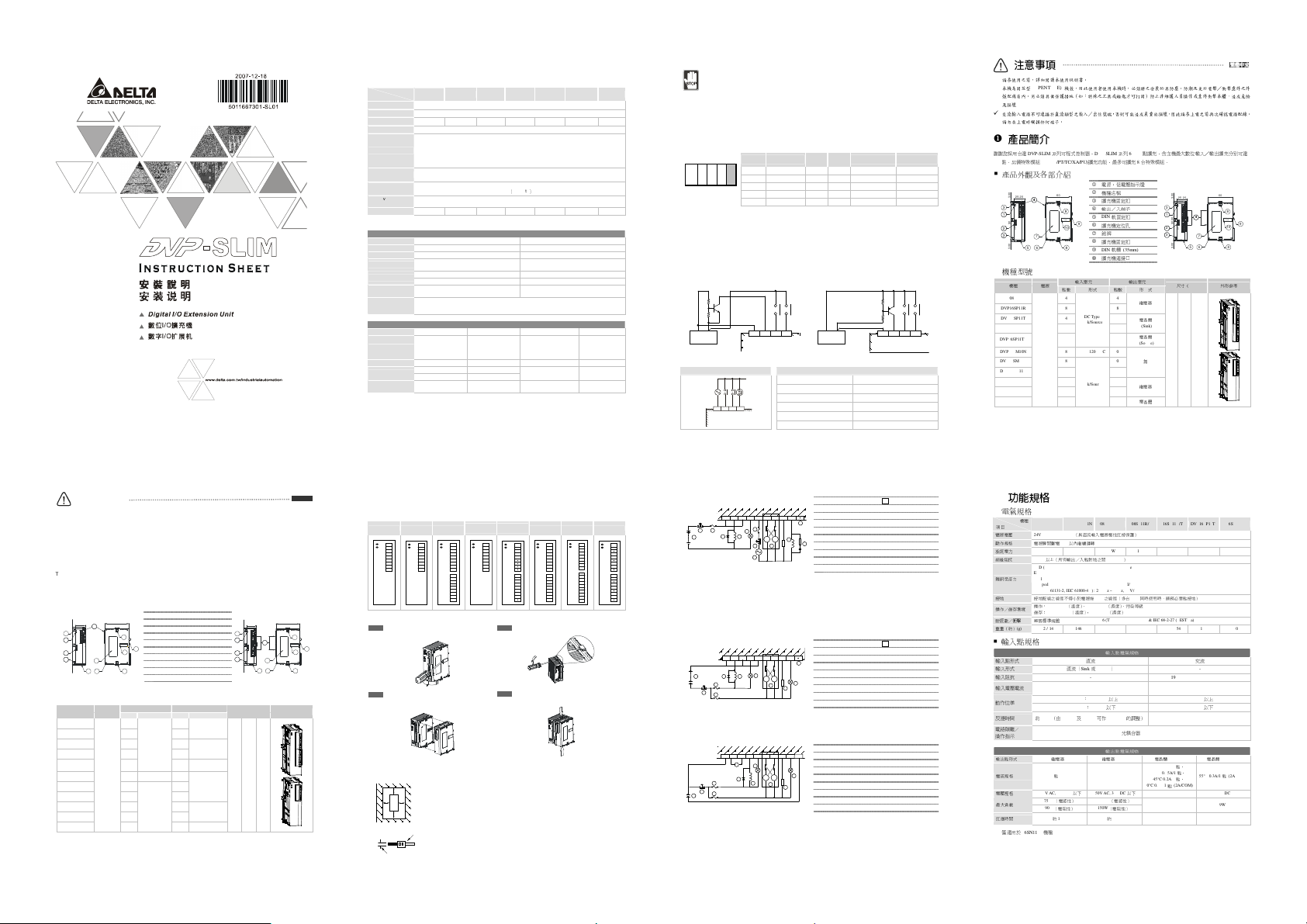
Specifications
Electrical Specifications
Model
Item
Power supply voltage 24V DC (-15%~20%) (with DC input polarity reverse protection)
Motion specification Within 5ms of the momentary power loss, the device will keep on operating
Power consumption 1W 2W 1.5W 1.5W 2W 2W 1.5W
Insulation resistance > 5MΩ (all I/O point-to-ground: 500V DC)
Noise immunity
Earth
Operation/storage
environment
Shock/vibration
immunity
Weight (g) 162 / 141 146 154 / 146 141 / 136 162 / 154 151 200
I/O Point Specifications
Input point type DC AC
Input type DC (Sink or Source) -
Input resistance - 19Kohm/50Hz 16Kohm/60Hz
Input current/voltage
Active level
Response time
Circuit
isolation/operation
instruction
Output type Relay-R Relay-R (*1) Transistor-T (Sink) Transistor-T (Source)
Current specification 1.5A/1 point (5A/COM) 6A/1 point
Voltage specification < 250V AC, 30V DC < 250V AC, 30V DC 30V DC 30V DC
Maximum load
Response time Approx. 10ms Approx. 10ms
*1: Only applicable in DVP06SN11R.
08SM11N
DVP16SM11N 08SN11R/T 08SP11R/T 16SP11R/T DVP16S P11TS 06SN11R
08SM10N
ESD (IEC 61131-2, IEC 61000-4-2): 8KV Air Discharge
EFT (IEC 61131-2, IEC 61000-4-4): Power Line: 2KV, Digital I/O: 1KV,
Analog & Communication I/O: 1KV
Damped-Oscillatory Wave: Power Line: 1KV, Digital I/O: 1KV
RS (IEC 61131-2, IEC 61000-4-3): 26MHz ~ 1GHz, 10V/m
The diameter of grounding wire shall not be less than that of L, N terminal of the power. When many PLCs
are in use at the same time, please make sure every PLC is properly grounded.
Operation: 0°C ~ 55°C (temperature), 50% ~ 95% (humidity), pollution degree 2
Storage: -25°C ~ 70°C (temperature), 5% ~ 95%(humidity)
International standards: IEC61131-2, IEC 68-2-6 (TEST Fc)/IEC61131-2 & IEC 68-2-27 (TEST Ea)
Input Point
24V DC 5mA
Off On: more than 16.5V DC More than 79V AC
On Off: less than 8V DC Less than 30V AC
Approx. 10ms, 0 ~ 15ms adjustable from D1020 and
D1021
By photocoupler / LED On
85 ~ 132V AC, 50 ~ 60Hz
9.2mA ,110V AC/60Hz
Off On < 15ms
On Off < 20ms
Output Point
55°C 0.1A/1 point
75VA (inductive) 24 0VA (inductive)
90W (resistive) 150W (resistive)
50°C 0.15A/1 point
45°C 0.2A/1 point
40°C 0.3A/1 point (2A/COM)
Off On 15us
On Off 25us
55°C 0.3A/1 point
(2A/COM)
9W 9W
Off On 15us
On Off 25us
DO NOT install PLC in an environment with
Dust, smoke, metallic debris, corrosive or flammable gas
High temperature, humidity
Direct shock and vibration
During the engineering
1. DO NOT drop tiny metallic conductor into the PLC when screwing and wiring.
2. There should be a margin of more than 50mm between the PLC and other control devices, and the PLC should be
placed away from high voltage wire and power equipment.
Arrangement of I/O Points
No matter the MPU with how many points you are using, the input point No. of the first connected extension unit has to
start from X20 and output point No. from Y20. The MPU is able to connect to maximum 14 digital extension units. The
connection of MPU and extension units is demonstrated in the figure below.
MPU EXT1 EXT2 EX T3 EX T4
The 3rd extension module 06SN11R will be regarded as 8-point output. The 2 output points of bigger No. will have no
actual corresponding output points.
The 4th extension module 08SP11R will be regarded as 8-point input/8-point output. The 4 input points and 4 output
points of bigger No. will have no actual corresponding input/output points. Therefore, it is suggested that they placed in
the end of the series connection to make the No. of I/I points continuous.
Input Point Wiring & Specification
There are two types of signals at input points, DC and AC, and there are two types of DC inputs, Sink and Source. The
wiring are as follows.
Sink Mode
+24V 0V
DC Power Supply
AC Wiring:
85~13 2VAC
PLC Model
MPU SS/SA/SX/SC 8 4/6 X0 ~ X7, X10, X11 Y0 ~ Y5, X10, X11
EXT1 16SP11T 8 8 X20 ~ X27 Y20 ~ Y27
EXT2 08SM11N 8 0 X30 ~ X37 -
EXT3 06SN11R 0 6 - Y30 ~ Y35
EXT4 08SP11R 4 4 X40 ~ X43 Y40 ~ Y43
S/S X0 X1 X2
Wiring Loop 110V AC Input Specification
Prox.
50/6 0Hz
Sens or
COM X0 X1 X2
DVP08SM 10N
Input
Output
Input point No. Output point No.
points
points
Source Mode
+24V 0V
DC Power Supply
Sink mode
Input voltage 85 ~ 132V AC, 50 ~ 60Hz
Input resistance 19Kohm/50Hz, 16Kohm/60Hz
Input current 9.2mA 110V AC/60Hz
On/Off voltage level 79V 3.8mA/30V 2.5mA
Response time 15ms
Circuit isolation/operation instruction By photocoupler / LED On
S/S X0 X1 X2
Source mode
注意事項
請在使用之前,詳細閱讀本使用說明書。
本機為開放型
(OPEN TYPE)
殼配線箱內。另必須具備保護措施(如:特殊之工具或鑰匙才可打開)防止非維護人員操作或意外衝擊本體,造成危險
及損壞
交流輸入電源不可連接於直流類型之輸入/出信號端,否則可能造成嚴重的損壞,因此請在上電之前再次確認電源配線。
請勿在上電時觸摸任何端子。
產品簡介
謝謝您採用台達
DVP-SLIM
256
點。另備特殊模組
(AD/DA/PT/TC/XA/PU)
產品外觀及各部介紹
25.20
POWER
L.V
3
1
0
0
.
0
9
P
V
2
D
3
7
0
0
.
5 6
3
機種型號
機種 電源
DVP08SP11R 4 4
DVP16SP11R 8 8
DVP08SP11T 4 4
DVP16SP11T 8 8
DVP16SP11TS 8
24V DC
DVP08SM10N 8 100 ~ 120V AC 0
DVP08SM11N 8 0
DVP16SM11N 16 0
DVP08SN11R 0 8
DVP06SN11R 0 6
DVP08SN11T
機殼,因此使用者使用本機時,必須將之安裝於具防塵、防潮及免於電擊/衝擊意外之外
系列可程式控制器。
DVP-SLIM系列6 ~ 16
擴充功能,最多可擴充8台特殊模組。
1
2
60
3
4
5
EXTENSION
PORT
9
6
10
7
8
9
輸入單元
點數 形式 點數 形 式
DC Type
Sink/Source
DC Type
Sink/Source
0
點擴充,含主機最大數位輸入/輸出擴充分別可達
電源、低電壓指示燈
機種名稱
擴充機固定扣
輸出/入端子
DIN
軌固定扣
擴充機定位孔
銘牌
擴充機固定扣
DIN軌糟 (35mm)
擴充機連接口
輸出單元
繼電器
電晶體
(Sink)
電晶體
8
(Source)
無
繼電器
電晶體
8
25.2 0
POWER
L.V
3
1
0
0
.
0
9
P
V
2
D
3
0
0
.
3
尺寸
25.2 90 60
(mm)
繁體中文
繁體中文
繁體中文繁體中文
60
●
●
●
●
44
EXTENSION
PORT
●
7
65
外形參考
Warning
Please read this instruction sheet carefully before use.
DVP-SLIM is an OPEN-TYPE device and therefore should be installed in an enclosure free of airborne dust, humidity,
electric shock and vibration. The enclosure should prevent non-maintenance staff from operating the device (e.g. key
or specific tools are required to open the enclosure) in case danger and damage on the device may occur.
DO NOT connect input AC power supply to any of the I/O terminals; otherwise serious damage may occur. Check all
the wiring again before switching on the power. DO NOT touch any terminal when the power is switched on.
Introduction
Thank you for choosing Delta DVP-Slim series programmable logic controller. DVP-Slim digital I/O extension unit offers 6 ~
16 points, and the maximum digital I/O extension points (including the MPU) can reach 256 points. In addition, maximum 8
additional special modules (AD/DA/PT/TC/XA/PU) can be extended to DVP-Slim series extension unit.
Product Profile & Outline
25. 20
POWER
L.V
3
1
0
0
.
0
9
P
V
2
D
3
0
0
.
5 6
3
Model Information
Model name
DVP08SP11R 4 4
DVP16SP11R 8 8
DVP08SP11T 4 4
DVP16SP11T 8 8
DVP16SP11TS
DVP08SM10N 8 100 ~ 120V AC 0
DVP08SM11N 8 0
DVP16SM11N 16 0
DVP08SN11R 0 8
DVP06SN11R 0 6
DVP08SN11T
1
60
2
3
4
8
5
EXTENSION
PORT
9
6
10
7
24V DC
7
8
9
Input Output
Power
supply
Points Type Points Type
DC Type
Sink/Source
8
DC Type
Sink/Source
0
POWER, L.V (low voltage) indicator
Model name
Extension unit fixing clip
I/O terminals
DIN rail clip
Extension unit positioning hole
Nameplate
Extension unit fixing clip
DIN rail (35mm)
Connection port for extension unit
Relay
Transistor
(Sink)
Transistor
8
(Source)
N/A
Relay
8 Transistor
25.2 0
POWER
L.V
3
●
●
●
1
●
44
0
0
.
0
9
P
V
2
D
●
3
7
0
0
.
65
3
Dimension (mm) Outline
25.2 90 60
60
ENGLISH
EXTENSION
PORT
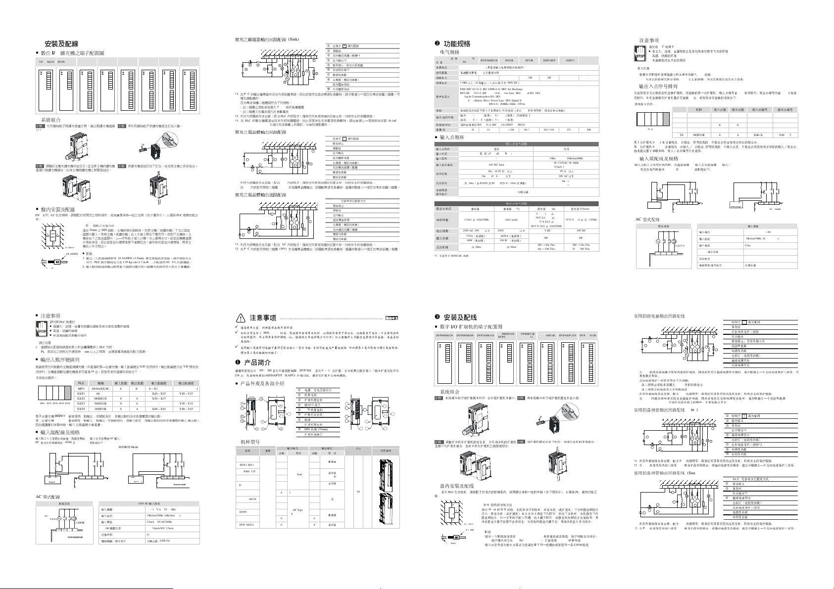
Installation & Wiring
Terminals of DVP-Slim
DVP08SM11N DVP08SM10N DVP16SM11N
S/S
COM
X0
X0
X1
X1
X2
X2
X3
X3
X4
X4
X5
X5
X6
X6
X7
X7
Connection
Step 1 Screw open the side cover of the extension unit,
and you will see the connection port.
Step 3 Adjust the positioning hole of the MPU and the
extension unit. Meet the connection port on the MPU with
the extension unit to tightly connect the two.
Installation & Wiring
Install the PLC in an enclosure with sufficient space around it to allow heat dissipation (as shown in the figure below).
D
DVP
DD
MPU
D
22-16AWG
< 1.5mm
DVP08SN11R
DVP08SP11R
DVP08SN11T
S/S
C0
X0
Y0
X1
Y1
X2
Y2
X3
Y3
X4
Y4
X5
Y5
X6
Y6
X7
Y7
S/S
X10
X11
X12
X13
X14
X15
X16
X17
DVP16SP11R DVP16SP11TS DVP06SN11R
DVP08SP11T
S/S
X0
X1
X2
X3
C0
Y0
C1
Y1
C2
Y2
C3
Y3
S/S
S/S
X0
X0
X1
X1
X2
X2
X3
X3
X4
X4
X5
X5
X6
X6
X7
X7
UP
C0
Y0
Y0
Y1
Y1
Y2
Y2
Y3
Y3
Y4
Y4
Y5
Y5
Y6
Y6
Y7
Y7
ZP
Step 2 Lift the fixing clip by the screwdriver.
How to install DIN rail
DVP-PLC can be secured to a cabinet by using the DIN rail of 35mm in height and
stop any side-to-side movement of the PLC and reduce the chance of wires being
loosen. A small retaining clip is at the bottom
place the clip onto the rail and gently push it up. To remove it, pull the retaining clip
down and gently remove the PLC from the DIN rail.
Wiring
1. Use 22-16AWG (1.5mm) single or multiple core wire on I/O wiring terminals. The
specification of the terminal is shown in the figure on the left hand side. The PLC
terminal screws shall be tightened to 1.95kg-cm (1.7 in-lbs). Use 65/75°C copper
wires only.
2. DO NOT place the I/O signal wires and power supply wire in the same wiring duct.
Step 4 Fasten the fixing clip on the extension unit to
complete the connection.
C0
Y0
C1
Y1
C2
Y2
C3
Y3
C4
Y4
C5
Y5
Relay Output Wiring Circuit (Sink):
MC2 MC1
5 2
9
*1: There is no internal protection circuit in the output relay of the PLC; therefore when activating an inductive load, we
suggest you parallely connect a reverse current protection diode to extend the life of the contact.
- The diode has to be able to endure max. 5 ~ 10 times of load voltage.
- The positive current of the diode has to be bigger than load current.
*2: Manual exclusive output uses external circuit and forms an interlock, together with the PLC internal program, to ensure
safety protection in case of any unexpected errors.
*3: There is no internal protection circuit in the output relay of the PLC; therefore when activating an inductive load, we
suggest you parallely connect a surge absorber (0.1uF + “100ohm to 120ohm”) to reduce the noise on AC load and
extend the life of the contact.
Transistor Output Wiring Circuit (Sink):
5 7 8
2
*1: Manual exclusive output uses external circuit and forms an interlock, together with the PLC internal program, to
ensure safety protection in case of any unexpected errors.
*2: Use a zener diode (39V) in the PLC to protect the transistor output. When activating inductive load, we sugget you
parallely connect a reverse current protection diode.
Transistor Output Wiring Loop (Source):
2
5
*1: Manual exclusive output uses external circuit and forms an interlock, together with the PLC internal program, to
ensure safety protection in case of any unexpected errors.
*2: Use a zener diode (39V) in the PLC to protect the transistor output. When activating inductive load, we sugget you
parallely connect a reverse current protection diode.
2
8
3 7
3
3
3
3
MC2MC1
5 4
10
MC2
MC1
6
MC2M C1
4
MC2
MC1
1
6
MC2MC1
7
8
4
1
7
6
1
6
9
6
9
DO NOT wire empty terminal •
1
Fuse
2
Reverse current protection diode*1
3
Manual exclusive output*2
4
Emergency stop: by external switch
5
Surge absorber*3
6
Inductive load
7
Incandescent light (resistive load)
8
DC power supply
9
AC power supply
DO NOT wire empty terminal •
1
Emergency stop
2
Fuse
3
Manual exclusive output*1
4
DC power supply
5
Incandescent light (resistive load)
6
Reverse current protection diode*2
7
Inductive load
8
Resistive load
9
Y6,Y7 (refer to other wiring methods)
1
Emergency stop
2
Fuse
3
Manual exclusive output*1
4
DC power supply
5
Incandescent light (resistive load)
6
Reverse current protection diode*2
7
Inductive load
8
Resistive load
9
功能規格
電氣規格
機種
項目
電源電壓
動作規格 電源瞬間斷電
消耗電力
絕緣阻抗
雜訊免疫力
接地 接地配線之線徑不得小於電源端
操作/儲存環境
耐振動/衝擊
重量(約)
輸入點規格
輸入點形式
輸入形式
輸入阻抗
輸入電壓電流
動作位準
反應時間 約
電路隔離
操作指示
輸出點形式
電流規格
電壓規格
最大負載
反應時間
*1:
僅適用於
08SM11N
DVP16SM11N 08SN11R/T 08SP11R/T 16SP11R/T DVP16SP11TS 06SN11R
08SM10N
24V DC (-15% ~ 20%)
1W 2W 1.5W 1.5W 2W 2W 1.5W
5 MΩ
(g) 162 / 141 146 154 / 146 141 / 136 162 / 154 151 200
/
1.5A/1點 (5A/COM)
2 50V AC, 30V DC以下 250V AC, 30V DC以下
06SN11R 機種
(具直流輸入電源極性反接保護)
5ms
以內繼續運轉
以上(所有輸出/入點對地之間
ESD (IEC 61131-2, IEC 61000-4-2): 8KV Air Discharge
EFT (IEC 61131-2, IEC 61000-4-4): Power Line: 2KV, Digital I/O: 1KV,
Analog & Communication I/O: 1KV
Damped-Oscillatory Wave: Power Line: 1KV, Digital I/O: 1KV
RS (IEC 61131-2, IEC 61000-4-3): 26MHz ~ 1GHz, 10V/m
操作:
0°C ~ 55°C
(溫度),
儲存:
國際標準規範
50% ~ 95%
-25°C ~ 70°C
(溫度),
5% ~ 95%
I EC61131-2, IEC 68-2-6 (TEST Fc)/ IEC61131-2 & IEC 68-2-27 (TEST Ea)
直流
直流(
Sink或Source)
- 19Kohm/50Hz 16Kohm/60Hz
24V DC 5mA
Off → On:16.5V DC以上 79V AC以上
On → Off:8 V DC以下 30V AC以下
10ms(由D1020及D1021可作0 ~ 15ms
繼電器
-R
75VA
(電感性)
240VA
90W
(電阻性)
1 50W
約
10ms
500V DC)
L, N
之線徑(多台
(濕度),污染等級
輸入點電氣規格
輸出點電氣規格
繼電器
6A/1 point
約
(濕度)
-R (*1)
(電感性)
(電阻性)
10ms
光耦合器
PLC
同時使用時,請務必單點接地)
2
的調整)
/ LED On
40°C 0.3A/1點 ( 2A/COM)
85~132VAC 50~60Hz
9.2mA 110VAC/60Hz
Off On < 15ms
On Off < 20ms
電晶體
-T (Sink)
55°C 0.1A/1點、
50°C 0.15A/1點、
45°C 0.2A/1點、
30V DC 30V DC
9W 9W
Off → On 15us
On → Off 25us
交流
-
電晶體
-T (Source)
55°C 0.3A/1點 (2A/COM)
Off → On 15us
On → Off 25us
Page 2
D > 50mm
85~132VAC
DVP08SM10N
C0C1Y0Y4C2Y2Y3
Y5
Y1
C0C1Y0Y4C2Y2Y3Y5Y1
ZPY6Y7Y1Y4Y3Y2Y0Y5
UP
8
8
9
10
4
4
3
.
0
0
3
.00
10
C0C1Y0Y4C2Y2Y3
Y5
Y1
C0C1Y0Y4C2Y2Y3Y5Y1
ZPY6Y7Y1Y4Y3Y2Y0Y5
UP
安裝及配線
數位I/O
DVP08SM11N DVP08SM10N DVP16SM11N
S/S
X0
X1
X2
X3
X4
X5
X6
X7
系統組合
步驟1 利用螺絲起子將擴充側蓋打開,會出現擴充機連接
口。
步驟3 調整好主機和擴充機的定位孔,並且將主機的擴充機
連接口與擴充機接合,此時主機與擴充機之間緊密結合。
擴充機之端子配置圖
COM
X0
X1
X2
X3
X4
X5
X6
X7
DVP08SN11R
DVP08SP11R
DVP08SN11T
S/S
X0
X1
X2
X3
X4
X5
X6
X7
S/S
X10
X11
X12
X13
X14
X15
X16
X17
DVP08SP11T
C0
S/S
Y0
X0
Y1
X1
Y2
X2
Y3
X3
Y4
Y5
Y6
Y7
C0
Y0
C1
Y1
C2
Y2
C3
Y3
步驟2 再利用螺絲起子將擴充機固定扣往上撥。
步驟4 將擴充機固定扣往下扣住,完成與主機之系統組合。
盤內安裝及配線
DVP系列PLC
常。
注意事項
施工注意
1.
鎖鏍絲及配線時請避免微小的金屬導體掉入
2. PLC
輸出入點序號排列
無論使用任何點數的主機連接擴充機,所連接的第一台擴充機,輸入點編號由
序排列,主機連接數位擴充機最多可連接14台,若使用者所連接的系統如下:
系統組合範例:
MPU EXT1 EXT2 EX T3 EX T4
第3台擴充機
第4台擴充機
因此建議置於
輸入端配線及規格
輸入點之入力信號共有兩種:為直流電源DC輸入及交流電源AC輸入。
DC
型式共有兩種接法,
SINK Mode SOURCE Mode
AC
型式配線
在安裝時,請裝配於封閉式之控制箱內,其周圍應保持一定之空間(如下圖所示),以確保
DIN
鋁軌之安裝方法
D
DVP
MPU
< 1.5mm
請勿將
與其它之控制元件應保持
適合
DD
塑膠片壓入,再將主機(或擴充機)由上方掛上再往下壓即可。欲取下主機時,主
機背面下之固定塑膠片,以一字形起子插入凹槽,向上撐開即可,該固定機構塑膠
片為保持型,因此該固定片撐開後便不會彈回去,當所有的固定片撐開後,再將主
D
機往上外方取出。
22-16AWG
1.
2.
PLC
裝置於
落塵大、油煙、金屬性粉塵及腐蝕性或可燃性氣體的環境
高溫、結露的環境
有直接振動及衝擊的場所
50mm
35mm之DIN
鋁軌,主機欲掛於鋁軌時,先將主機(或擴充機)下方之固定
配線
輸出/入配線端請使用
所示。
輸入點信號線與輸出點等動力線請勿置於同一線糟內或使用同一多芯之電纜線。
PLC
端子鏍絲扭力為
22-16AWG (1.5mm)
1.95 kg-cm (1.7 in-lbs)
PLC
內部。
以上之間隔,並應遠離高壓線及動力設備。
06SN11R
會被視為8點輸出,序號較高的2個
08SP11R
會被視為8點輸入/8點輸出,序號較高的4個
串聯末
端,輸入/出點編號才會連續。
SINK及SOURCE
+24V 0V
DC Power Supply
配線回路
50/60H z
COM X0 X1 X2
機種 輸入點數 輸出點數 輸入點編號 輸出點編號
PLC
MPU SS/SA/SX/SC 8 4/6 X0 ~ X7, X10, X11 Y0 ~ Y5, X10, X11
EXT1 16SP11T 8 8 X20 ~ X27 Y20 ~ Y27
EXT2 08SM11N 8 0 X30 ~ X37 -
EXT3 06SN11R 0 6 - Y30 ~ Y35
EXT4 08SP11R 4 4 X40 ~ X43 Y40 ~ Y43
,其配線如下:
S/S X0 X1 X2
近接開關
輸出點則沒有對應實際的輸出點。
輸入點及4個
+24V 0V
Sink mode
DC Power Supply
輸入電壓
輸入阻抗
19Kohm/50Hz, 16Kohm/60Hz
輸入電流
On/Off
電壓位準
反應時間
電路隔離/操作指示
DVP16SP11R DVP16SP11TS DVP 06SN11R
S/S
S/S
X0
X0
X1
X1
X2
X2
X3
X3
X4
X4
X5
X5
X6
X6
X7
X7
UP
C0
Y0
Y0
Y1
Y1
Y2
Y2
Y3
Y3
Y4
Y4
Y5
Y5
Y6
Y6
Y7
Y7
ZP
PLC
單蕊祼線或多蕊線,端子規格如左
。只能使用
60/75
°C
的銅導線。
X20
依序排列,輸出點編號亦由
輸出點則沒有對應實際的輸入/輸出點,
S/S X0 X1 X2
Source mode
110V AC
輸入規格
85 ~ 132V AC, 50 ~ 60Hz
9.2mA 110V AC/60Hz
79V 3.8mA/30V 2.5mA
15ms
光耦合器/
LED On
散熱功能正
Y20
開始依
實用之繼電器輸出回路配線
5 2
C0
Y0
C1
Y1
C2
Y2
C3
Y3
C4
Y4
C5
Y5
9
*1: 在PLC
的輸出繼電器並沒有內部保護電路,因此若使用在直流電感性負載時,請並聯接上一個反向電流保
增加接點壽命
反向電流保
護二極體須符
-
此二極體必須能承受最大
-
此二極體正向電流須大於負載電流
*2:
利用外部電路形成互鎖,配合
*3: 在PLC
的輸出繼電器並沒有內部保護電路,因此若使用在交流電感性負載時,請並聯接上一
“100ohm to 120ohm”)
實用之電晶體輸出回路配線
5 7 8
2
*1:
利用外部電路形成互鎖,配合
*2: 在PLC
內部使用
實用之電晶體輸出迴路配線
2
5
*1:
利用外部電路形成互鎖,配合
*2: 在PLC
內部使用
注意事項
请在使用之前,详细阅读本使用说明书
本机为开放型
壳配线箱内。另必须具备保护措施(如:特殊的工具或钥匙才可打开)防止非维护人员操作或意外冲击本体,造成危险
及损坏
。
交流输入电源不可连接于直流类型的输入/出信号端,否则可能造成严重的损坏,因此请在上电之前再次确认电源配线
请勿在上电时触摸任何端子
產品簡介
谢谢您采用台达
256
点。另备特殊模块
产品外观及各部介绍
25.2 0
POWER
L.V
3
1
0
0
.
0
9
P
V
2
D
3
0
0
.
3
机种型号
机种 电源
DVP08SP11R 4 4
DVP16SP11R 8 8
DVP08SP11T 4 4
DVP16SP11T 8 8
DVP16SP11TS 8
DVP08SM10N 8 100 ~ 120V AC 0
DVP08SM11N 8 0
DVP16SM11N 16 0
DVP08SN11R 0 8
DVP06SN11R 0 6
DVP08SN11T
(Sink)
MC2 MC1
2
8
3 7
。
3
3
齊納二極
3
3
齊納二極
(OPEN TYPE)
DVP-SLIM
(AD/DA/PT/TC/XA/PU)
7
5 6
24V DC
MC2MC1
5 4
10
合下列規格:
5 ~ 10
倍的負載
電壓
PLC
內部程式,確保任何異常
可減少交流負載上的雜訊,可增加接點壽命。
(Sink)
MC2
MC1
6
MC2M C1
4
PLC
內部程式,確保任何異常
體
(39V)
來保護電晶
(Source)
MC2 M C1
1
6
MC2MC1
7
8
4
PLC
內部程式,確保任何異常
體
(39V)
來保護電晶
。
机壳,因此使用者使用本机时,必须将其安装于具防尘、防潮及免于电击/冲击意外的外
。
系列可编程控制器。
DVP-SLIM系列6 ~ 16
扩展功能,最多可扩展8台特殊模块。
1
2
60
3
4
5
EXTENSION
PORT
6
7
8
9
输入单元
点数 形式 点数 形 式
DC Type
Sink/Source
DC Type
Sink/Source
0
空端子
•
1
保險絲
2
反向電流保護二極體
3
1
互斥輸出
*2
4
緊急停止:使用外部開關
5
突波吸收器
6
7
6
電感性負載
7
白熾燈(電阻性負載)
8
直流電源供給
9
交流電源供給
突發狀況發生時,均有安全的保護措
空端子
•
1
緊急停止
2
保險絲
3
1
互斥輸出
*1
4
直流電源供應
5
白熾燈(電阻性負載)
6
6
9
反向電流保護二極體
7
電感性負載
8
電阻性負載
9
突發狀況發生時,均有安全的保護措
體輸出,若驅動電感性負載時,建議並聯接上一個反向電流保
Y6,Y7
可參考其它配線方式
1
緊急停止
2
保險絲
3
互斥輸出
*1
4
直流電源供應
5
6
白熾燈(電阻性負載)
6
9
反向電流保護二極體
7
電感性負載
8
電阻性負載
9
突發狀況發生時,均有安全的保護措
體輸出,若驅動電感性負載時,建議並聯接上一個反向電流保
点扩展,含主机最大数字输入/输出扩展分别可达
电源、低电压指示灯
机种名称
扩展机固定扣
输出/入端子
DIN
轨固定扣
扩展机定位孔
铭牌
扩展机固定扣
DIN轨槽 (35mm)
扩展机连接口
输出单元
继电器
晶体管
(Sink)
晶体管
8
( Source)
无
继电器
8
晶体管
請勿配線
*1
*3
請勿配線
*2
*2
25.20
POWER
L.V
3
●
●
●
1
●
0
0
.
0
9
P
V
2
D
●
3
0
0
.
3
尺寸
mm
25.2 90 60
施。
個突波吸收
施。
施。
44
7
65 8
功能規格
电气规格
机 种
项 目
电源电压
动作规格 电源瞬间断电
消耗电力
绝缘阻抗
護二極
體,可
器
(0.1uF +
噪声免疫力
接地 接地配线的线径不得小于电源端
操作/储存环境
耐振动/冲击
重量(约
输入点规格
输入点形式
输入形式
输入阻抗
输入电压电流
动作位准
.
護二極
體。
反应时间 约
电路隔离
操作指示
输出点形式
电流规格
电压规格
.
護二極
體。
最大负载
反应时间
*1:
仅适用于
08SM11N
DVP16SM11N 08SN11R/T 08SP11R/T 16SP11R/T DVP16SP11TS 06SN11R
08SM10N
24V DC (-15%~20%)
5 MΩ
), (g)
24V DC 5mA
/
06SN11R 机种
(具直流输入电源极性反接保护)
5ms
以内继续运转
1W 2W 1.5W 1.5W 2W 2W 1.5W
以上(所有输出/入点对地之间
ESD (IEC 61131-2, IEC 61000-4-2): 8KV Air Discharge
EFT (IEC 61131-2, IEC 61000-4-4): Power Line: 2KV, Digital I/O: 1KV,
Analog & Communication I/O: 1KV
Damped-Oscillatory Wave: Power Line: 1KV, Digital I/O: 1KV
RS (IEC 61131-2, IEC 61000-4-3): 26MHz~1GHz, 10V/m
操作:
0°C ~ 55°C
(温度),
储存:
国际标准规范
162 / 141 146 154 / 146 141 / 136 162 / 154 151 200
50 ~ 95%
-25°C ~70°C
(温度),
5 ~ 95%
IEC61131-2, IEC 68-2-6 (TEST Fc)/IEC61131-2 & IEC 68-2-27 (TEST Ea)
直流
直 流(
SINK或SOURCE) -
Off → On:16.5V DC以上 79V AC以上
On → Off:8 V DC以下 30V AC以下
10ms(由D1020及D1021可作0 ~ 15ms
继电器
-R
1.5A/1点 (5A/COM)
250V AC, 30V DC以下 250V AC, 30V DC以下 30V DC 30V DC
75VA
(电感性)
240VA
90W
(电阻性)
150 W
约
10ms
500V DC)
L, N
的线径(多台
PLC
同时使用时,请务必单点接地)
(湿度),污染等级
2
(湿度)
输入点电气规格
- 19Kohm/50Hz 16Kohm/ 60Hz
的调整)
光耦合器
/ LED On
输出点电气规格
继电器
-R (*1)
晶体管
-T (Sink)
55°C 0.1A/1点、
(电感性)
(电阻性)
10ms
50°C 0.15A/1点、
45°C 0.2A/1点、
40°C 0.3A/1点 (2A/COM)
9W 9W
Off → On 15us
On → Off 25us
6A/1 point
约
交流
85~132VAC 50~60Hz
9.2mA 110VAC/60Hz
Off On < 15 ms
On Off < 20 ms
晶体管
55°C 0.3A/1点 (2A/COM)
-T (Source)
Off → On 15us
On → Off 25us
简体中文
60
外形参考
8
EXTENSION
PORT
简体中文
简体中文简体中文
。
9
安裝及配線
数字I/O
DVP08SM11N DVP08SM10N DVP16SM11N
系统组合
步骤11利用螺丝起子将扩展侧盖打开,会出现扩展机连接口。
步骤3 调整好主机和扩展机的定位孔,并且将主机的扩展机
连接口与扩展机接合,此时主机与扩展机之间紧密结合。
盘内安装及配线
DVP系列PLC
常。
扩展机的端子配置图
S/S
COM
X0
X0
X1
X1
X2
X2
X3
X3
X4
X4
X5
X5
X6
X6
X7
X7
在安装时,请装配于封闭式的控制箱内,其周围应保持一定的空间(如下图所示),以确保
D
DVP
DD
MPU
D
D > 50mm
22-16AWG
< 1.5mm
DVP08SN11R
DVP08SP11R
DVP08SN11T
S/S
X0
X1
X2
X3
X4
X5
X6
X7
S/S
X10
X11
X12
X13
X14
X15
X16
X17
DVP08SP11T
C0
Y0
Y1
Y2
Y3
Y4
Y5
Y6
Y7
步骤2 再利用螺丝起子将扩展机固定扣往上拨。
步骤4 将扩展机固定扣往下扣住,完成与主机的系统组合。
DIN
铝轨的安装方法
适合
压入,再将主机(或扩展机)由上方挂上再往下压即可。欲取下主机时,主机背面下的
固定塑胶片,以一字形起子插入凹槽,向上撑开即可,该固定机构塑胶片为保持型,因
此该固定片撑开后便不会弹回去,当所有的固定片撑开后,再将主机往上外方取出。
配线
1.
2.
35mm的DIN
铝轨,主机欲挂于铝轨时,先将主机(或扩展机)下方的固定塑胶片
输出/入配线端请使用
PLC
输入点信号线与输出点等动力线请勿置于同一线槽内或使用同一多芯的电缆线。
端子镙丝扭力为
22-16AWG (1.5mm)
1.95 kg-cm (1.7 in-lbs)
DVP16SP11R DVP16SP11TS DVP06SN11R
S/S
S/S
X0
X0
X1
X1
X2
X2
X3
X3
X4
X5
X6
X7
C0
C0
Y0
Y0
C1
Y1
Y1
Y2
C2
Y3
Y2
Y4
C3
Y5
Y3
Y6
Y7
单蕊祼线或多蕊线,端子规格如左所示。
。只能使用
60/75
°C
S/S
X0
X1
X2
X3
X4
X5
X6
X7
UP
Y0
Y1
Y2
Y3
Y4
Y5
Y6
Y7
ZP
PLC
的铜导线。
散热功能正
C0
Y0
C1
Y1
C2
Y2
C3
Y3
C4
Y4
C5
Y5
注意事项
请勿将
PLC
装置于
落尘大、油烟、金属性粉尘及腐蚀性或可燃性气体的环境
高温、结露的环境
有直接振动及冲击的场所
施工注意
1.
锁镙丝及配线时请避免微小的金属导体掉入
2. PLC
与其它的控制元件应保持
输出入点序号排列
无论使用任何点数的主机连接扩展机,所连接的第一台扩展机,输入点编号由
序排列,主机连接数字扩展机最多可连接
系统组合范例:
MPU EXT1 EXT2 EX T3 EX T4
第3台扩展机
06SN11R
第4台扩展机
08SP11R
因此建议置于
串联末
输入端配线及规格
输入点的入力信号共有两种:为直流电源DC输入及交流电源AC输入。
DC
型式共有两种接法,
SINK Mode SOURCE Mode
+24V 0V
DC Power Supply
AC
型式配线
85~13 2VAC
50/6 0Hz
COM X0 X1 X2
实用的继电器输出回路配线
5 2
9
*1: 在PLC
的输出继电器并没有内部保护电路,因此若使用在直流电感性负载时,请并联接上一个反向电流保
增加接点寿命
反向电流保
护二极管须符
-
此
二极管必须能承受
-
此
二极管
正向电流须大于负载电流
*2:
利用外部电路形成互锁,配合
*3: 在PLC
的输出继电器并没有内部保护电路,因此若使用在交流电感性负载时,请并联接上一
“100ohm to 120ohm”)
实用的晶体管输出回路配线
5 7 8
2
*1:
利用外部电路形成互锁,配合
*2: 在PLC
内部使用
实用的晶体管输出回路配线
2
5
*1:
利用外部电路形成互锁,配合
*2: 在PLC
内部使用
PLC
50mm
以上的间隔,并应远离高压线及动力设备。
14
台,若使用者所连接的系统如下:
PLC
机种 输入点数 输出点数 输入点编号 输出点编号
MPU SS/SA/SX/SC 8 4/6 X0~X7, X10, X11 Y0~Y5, X10, X11
EXT1 16SP11T 8 8 X20~X27 Y20~Y27
EXT2 08SM11N 8 0 X30~X37 -
EXT3 06SN11R 0 6 - Y30~Y35
EXT4 08SP11R 4 4 X40~X43 Y40~Y43
会被视为8点输出,序号较高的2个
会被视为8点输入/8点输出,序号较高的4个
端,输入/出点编号才会连续。
SINK及SOURCE
,其配线如下:
S/S X0 X1 X2
Sink mode
配线回路
DVP08S M10N
近接开关
(Sink)
MC2 MC1
2
8
3 7
。
5 4
10
合下列规格:
最大
5 ~ 10
倍
的负载电压
PLC
内部程序,确保任何异常
可
减少交
流负载上的噪声,可增加接点寿命。
MC2MC1
(Sink)
MC2
MC1
6
PLC
内部程序,确保任何异常
(39V)
来保护晶体管
MC2MC1
4
3
3
齐纳二极管
(Source)
MC2
1
6
MC2MC1
7
8
3
3
齐纳二极管
PLC
内部程序,确保任何异常
(39V)
来保护晶体管
4
内部。
X20
输出点则没有对应实际的输出点。
输入点及4个
+24V 0V
DC Power Supply
输入电压
输入阻抗
输入电流
On/Off
反应时间
电路隔离/操作指示
7
110V AC
9.2mA, 110V AC/60Hz
电压位准
79V 3.8mA/30V 2.5mA
15ms
空端子
•
1
保险丝
2
反向电流保
3
1
互斥
输出
4
紧
急停止
5
突波吸收
6
6
电感性负载
7
白炽
灯(电阻性负载)
8
直流电源
9
交
流电源
突发状况发生时,均有安全的保护措
空端子
•
1
紧
急停止
2
保险丝
3
1
互斥
输出
4
直流电源供应
5
白炽
灯(电阻性负载)
6
6
9
反向电流保
7
电感性负载
8
电阻性负载
9
突发状况发生时,均有安全的保护措
输出,若驱动电感性负载时,建议并联接上一个反向电流保
Y6,Y7
1
紧
急停止
2
保险丝
3
MC1
输出,若驱动电感性负载时,建议并联接上一个反向电流保
4
5
6
6
9
7
8
9
突发状况发生时,均有安全的保护措
互斥
输出
直流电源供应
白炽
灯(电阻性负载)
反向电流保
电感性负载
电阻性负载
依序排列,输出点编号亦由
输出点则没有对应实际的输入/输出点,
输入规格
85 ~ 132V AC, 50 ~ 60Hz
19Kohm/50Hz, 16Kohm/60Hz
光耦合器
请勿配线
护二极管
*2
:使用外部开
器
*3
供给
供给
请勿配线
*1
护二极管
可参考其它配线方式
*1
护二极管
S/S X0 X1 X2
/ LED On
*1
关
*2
*2
Source mode
施。
个突波吸收
施。
.
施。
Y20
护二极管
器
护二极管
护二极管
(0.1uF +
开始依
,可
。
。
 Loading...