

Delta Electronics DOP-A80THTD1, DOP-A10THTD1, DOP-AE80THTD, DOP-E10THTD1, DOP-AS57BSTD Quick Start Manual
...

English
-1
Preface
Thank you for purchasing DELTA’s DOP-A, AE and AS series. This quick start will be helpful in the
installation, wiring and inspection of Delta HMI. Before using the product, please read this quick start
to ensure correct use. You should thoroughly understand all safety precautions before proceeding
with the installation, wiring and operation. Place this quick start in a safe location for future
reference. Please observe the following precautions:
Install the product in a clean and dry location free from corrosive and inflammable gases or
liquids.
Ensure that all wiring instructions and recommendations are followed.
Ensure that HMI is correctly connected to a ground. The grounding method must comply
with the electrical standard of the country.
Do not modify or remove wiring when power is applied to HMI.
Do not touch the power supply during operation. Otherwise, it may cause electric shock.
For the information of HMI software operation, software installation and hardware wiring,
please refer to the HMI software manual.
If you have any questions during operation, please contact our local distributors or Delta sales
representative.
The content of this quick start may be revised without prior notice. Please consult our distributors or
download the most updated version at 0Hhttp://www.delta.com.tw/industrialautomation.
Safety Precautions
Carefully note and observe the following safety precautions when receiving, inspecting, installing,
operating, maintaining and troubleshooting. The following words, DANGER, WARNING and STOP are
used to mark safety precautions when using the Delta’s HMI product. Failure to observe these
precautions may void the warranty!
Installation
Comply with quick start for installation. Otherwise it may cause equipment
damage.
Do not install the product in a location that is outside the stated specification for
the HMI. Failure to observe this caution may result in electric shock, fire, or
personal injury.
Wiring
Connect the ground terminals to a class-3 ground (Ground resistance should not
exceed 100Ω). Improper grounding may result in communication error, electric
shock or fire.
Operation
The users should use Delta Screen Editor software to perform editing in Delta's HMI
product. To perform editing and confirming HMI programs without using Delta
Screen Editor software in Delta's HMI product may result in abnormal operation.

English
-2
Do not modify wiring during operation. Otherwise it may result in electric shock or
personal injury.
Never use a hard or pointed object to hit or strike the screen as doing this may
damage the screen and let the screen has not respond at all, and then cause HMI to
work abnormally..
Maintenance and Inspection
Do not touch any internal or exposed parts of the HMI as electrical shock may
result.
Do not remove operation panel while power is on. Otherwise electrical shock may
result.
Wait at least 10 minutes after power has been removed before touching any HMI
terminals or performing any wiring and/or inspection as an electrical charge may
still remain in the HMI with hazardous voltages even after power has been
removed.
Turn the power off before changing backup battery and check system settings after
finishing change. (all data will be cleared after changing battery).
Be sure the ventilation holes are not obstructed during operation. Otherwise
malfunction may result due to bad ventilation or overheating troubles.
Wiring Method
Remove the terminal block from the HMI before wiring.
Insert only one wire into one terminal on the terminal block.
If the wiring is in error, perform the wiring again with proper tools. Never use force
to remove the terminals or wires. Otherwise, it may result in malfunction or
damage.
For the power line that forced to take out, ensure to check wiring again and restart.
Communication Wiring
Comply with communication wiring specification for wiring.
Wiring length should comply with the stated specification for the HMI.
Proper grounding to avoid bad communication quality.
Installation and Storage Conditions
The product should be kept in the shipping carton before installation. In order to retain the warranty
coverage, the HMI should be stored properly when it is not to be used for an extended period of time.
Some storage suggestions are:
Store in a clean and dry location free from direct sunlight.
Store within an ambient temperature range of -20°C to +60°C (-4°F to 140°F).
Store within a relative humidity range of 10% to 90% and non-condensing.
Do not store the HMI in a place subjected to corrosive gases and liquids.
Correctly packaged and placed on a solid and durable surface.
Do not mount the HMI adjacent to heat-radiating elements or in direct sunlight.
Do not mount the HMI in a location subjected to corrosive gases, liquids, or airborne dust
or metallic particles.
Do not mount the HMI in a location where temperatures and humidity will exceed
specification.
Do not mount the HMI in a location where vibration and shock will exceed specification.
Do not mount the HMI in a location where it will be subjected to high levels of
electromagnetic radiation.

English
-3
Installation
Installation Note:
Improper installation will result in malfunction and greatly reduce the life of the HMI. Be
sure to follow the guidelines in this quick start when installing the HMI.
In order to ensure the HMI being well ventilated, make sure that the ventilation holes are
not obstructed and must provide sufficient free space around HMI.
For use on a flat surface of a Type 4X "Indoor Use Only" enclosure or equivalent.
Installation Method [A and AE Series]:
Step 1:
Ensure to put waterproof gasket into HMI and
then insert the HMI into the panel cutout.
Step 2:
Ensure to insert fasteners into the HMI’s insertion
slots and turn the screw till screws touch panel
cutout.
Step 3:
Turn the screw with less than torque 0.7N-M to avoid damage to plastic box. Torque:
6.17lb-inch(0.7N-M)
Installation Method [AS Series]:
Step 1:
Ensure to put waterproof gasket into HMI and
then insert the HMI into the panel cutout.
Step 2:
Ensure to insert fasteners into the HMI’s insertion
slots and turn the screw till screws touch panel
cutout.

English
-4
Step 3:
Turn the screw with less than torque 0.7N-M to avoid damage to plastic box. Torque:
6.17lb-inch(0.7N-M)
Power Line Installation
The specifications for power terminal wiring are shown in the table below:
Type Wire Gauge (AWG) Stripped length Torque
Solid 28~12 7~8 mm 5 kg-cm (4.3 lb-in)
Stranded 28~12 7~8 mm 5 kg-cm (4.3 lb-in)
The specifications for communication terminal wiring are shown in the table below (AS Series only):
Type Wire Gauge (AWG) Stripped length Torque
Solid
30 ~ 16 5 ~ 6 mm 2 kg-cm (1.7 lb-in)
Stranded
30 ~ 16 5 ~ 6 mm 2 kg-cm (1.7 lb-in)
Be sure to plug power line into HMI according to following arrow direction.
DOP-A80THTD1
DOP-AE80THTD
DOP-A(E)10THTD1
DOP-AS35THTD
DOP-AS38BSTD
DOP-AS57BSTD

English
-5
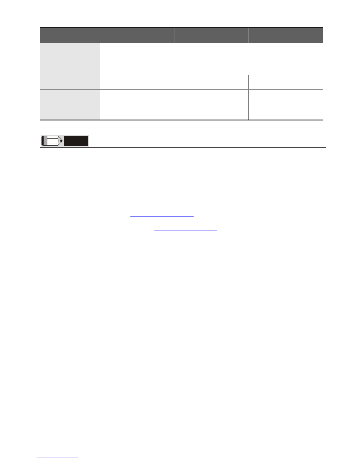
Basic Inspection
Item
Content
General Inspection
Periodically inspect the screws of the connection between the HMI and
device. Tighten screws as necessary as they may loosen due to vibration
and varying temperatures.
Ensure that oil, water, metallic particles or any foreign objects do not fall
inside the HMI, control panel or ventilation slots and holes. As these will
cause damage.
Ensure the correct installation and the control panel. It should be free from
airborne dust, harmful gases or liquids.
Inspection before
operation (power is
not applied)
Ensure that all wiring terminals are correctly insulated.
Ensure that all wiring is correct or damage and or malfunction may result.
Visually check to ensure that there are not any unused screws, metal
strips, any conductive or inflammable materials inside HMI.
Ensure to lower electromagnetic interference when devices are influenced
by it.
Ensure that the external applied voltage to HMI is correct and matched to
the controller.
Inspection before
operation (power is
applied)
Check if power LED lights.
Check if the communication among devices is normal.
Please contact our local distributors or Delta sales representative if there
are any abnormal conditions.
Pin Definition of Serial Communication
COM1 Port [A, AE and AS57BSTD Series]
COM Port PIN
Contact
RS-232
1
2 RXD
3 TXD
4
5 GND
6
7 RTS
8 CTS
9
Note: Blank = No Connection.
Pin

English
-6
COM2 Port [A Series]
COM Port PIN
MODE1 MODE2 MODE3
RS-232 RS-422 RS-485
1 RXD- D2 RXD RXD+ D+
3 TXD TXD+ D+
4 TXD- D5 GND
6 RTS-
7 RTS RTS+
8 CTS CTS+
9 CTS-
Note 1: Blank = No Connection.
Note 2: When selecting Mode3 (for RS-485), D+ indicates that PIN 2 and PIN 3 is connected,
and D- indicates that PIN 1 and PIN 4 is connected.
COM2 and COM3 Port [AE, A80THTD1 and A10THTD1 Series]
COM Port PIN
MODE1 MODE2 MODE3 MODE4 MODE5 MODE6
RS-232 RS-422 RS-485
RS-232*2 RS-422*2 RS-485*
2
COM2
1 RXD-
D- RXD1-
D1-
2 RXD RXD+
D+ RXD1 RXD1+
D1+
3 TXD TXD+
D+ TXD1 TXD1+
D1+
4 TXD-
D- TXD1-
D1-
5 GND
COM3
6 RTS-
TXD2-
D2-
7 RTS RTS+
TXD2 TXD2+
D2+
8 CTS CTS+
RXD2 RXD2+
D2+
9 CTS-
RXD2-
D2-
Note 1: Blank = No Connection.
Note 2: When selecting Mode3 (for RS-485), D+ indicates that PIN 2 and PIN 3 is connected,
and D- indicates that PIN 1 and PIN 4 is connected. When selecting Mode6 (for
RS-485), D1+ indicates that PIN 2 and PIN 3 is connected, D1- indicates that PIN 1
and PIN 4 is connected, D2+ indicates that PIN 7 and PIN 8 is connected, and D2indicates that PIN 6 and PIN 9 is connected.
COM1 and COM3 [AS38BSTD, AS35THTD Series]
COM Port PIN
MODE1 MODE2
RS-232 RS-232*2
COM1
1
2 RXD RXD1
3 TXD TXD1
4
5 GND
COM3
6
7 RTS TXD2
8 CTS RXD2
9
Note: Blank = No Connection.
Pin
Pin
Pin

English
-7
COM2 Port [AS38BSTD, AS35THTD Series]
COM Port PIN
MODE1 MODE2
RS-422 RS-485
R- RXD- D-
R+ RXD+ D+
T- TXD- D-
T+ TXD+ D+
G GND
Note 1: When selecting Mode2 (for RS-485), D+ indicates that R+ and T+ is connected, and
D- indicates that R- and T- is connected.
COM2 and COM3 Port [AS57BSTD Series]
COM Port PIN
MODE1 MODE2 MODE3
RS-485*2 RS-422*2
RS-422
COM2
R- D- RXD- RXD-
R+ D+ RXD+ RXD+
T- TXD- TXD-
T+ TXD+ TXD+
G GND
COM3
R- D- RXD- CTS-
R+ D+ RXD+ CTS+
T- TXD- RTS-
T+ TXD+ RTS+
Note 1: Blank = No Connection.
Note 2: When using RS-422 flow control, please refer to the COM3 Port signals table above
for pin assignments. At this time, COM2 and COM3 ports cannot be used individually.
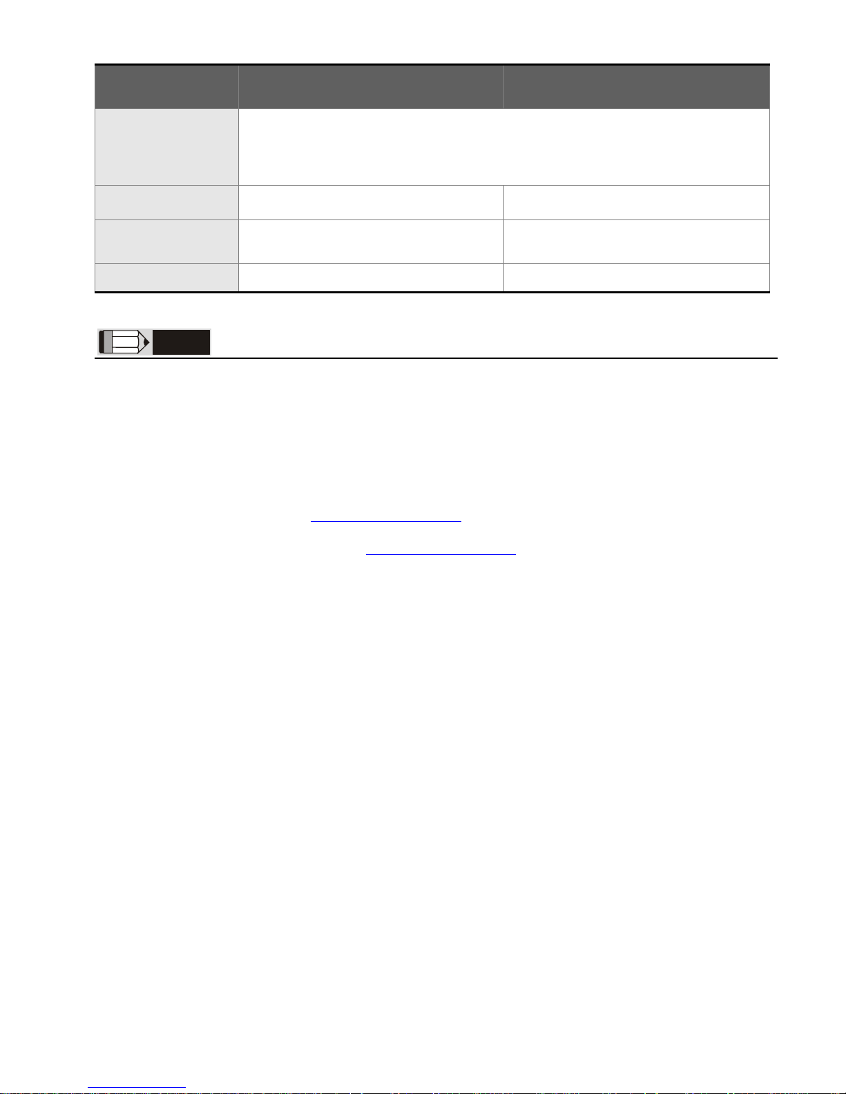
Comparison of Flow Control Protocols
COM
Port
DOP-AE Series DOP-A Series
DOP-AS57 Series
DOP-AS35 / AS38
Series
COM1
RS-232 flow control
supported
RS-232 flow
control
supported
RS-232 flow control
supported
RS-232 flow control
supported. But, when
RS-232 flow control
function is enabled,
COM3 can not be used.
COM2
RS-422 flow control
supported. But,
when RS-422 flow
control function is
enabled, COM3 can
not be used.
RS-422 flow
control
supported
RS-422 flow control
supported. But, when
RS-422 flow control
function is enabled,
COM3 can not be
used.
RS-422 flow control is
not supported.
COM3
N/A
RS-232 flow control
supported. But, when
RS-232 flow control
function is enabled,
COM3 can not be used.
Note: For more detailed information regarding the pin definition for flow control, please refer
to the pin definition of serial communication of each series.
COM2
COM3
R-

English
-8
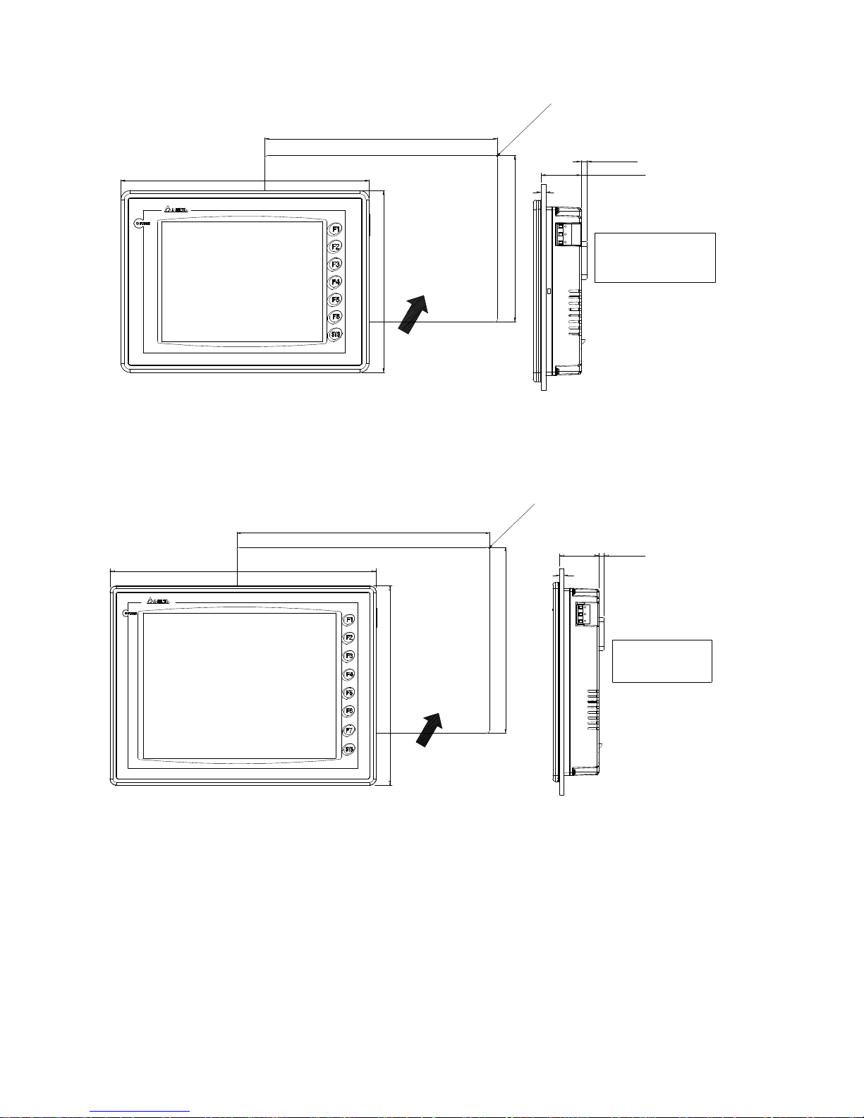
Dimensions
DOP-AS35THTD / DOP-AS38BSTD
118.8
+0.04+1
(4.68 )
140.8
104.8
0
0
(3.65 )
T=1.6mm(0.06in) ~
92.8
0
+1
3.0mm(0.12in)
NOTE:
0
+0.04
T
4-R3
36.7
DOP-AS57BSTD
0.12in(3.0mm)
T=0.06in(1.6mm) ~
(5.21 )
+1
0
+0.04
0
(6.79 )
0
+1 +0.04
0
144.1(5.67)
184.1(7.25)
6.1(0.24)39.0(1.54)
172.4
132.4
4-R3(0.12)
T
NOTE:
Units: mm
Units: mm
English
-9
DOP-A80THTD1 / DOP-AE80THTD
T=1.6mm(0.06in) ~
3.0mm(0.12in)
(1.75)
178.1(7.01)
243.1(9.57)
0
+1
231.4
0
(9.11 )
+0.04
+0.04
(6.55 )
0
+1
166.4
0
NOTE:
4
-
R
3
.
0
(
0
.
1
2
)
44.4
T
6.1(0.24)
DOP-A(E)10THTD1
3.0mm(0.12in)
+0.04
(11.22 )
+1
0
0
T=1.6mm(0.06in) ~
(8.27 )
+1
0
+0.04
0
210.2
285.2
4
-
R
3
.
0
(
0
.
1
2
)
NOTE:
T
297.1(11.70)
222.1(8.74)
43.1(1.70) 6.1(0.24)
Units: mm
Units: mm

English
-
1
0
Specifications
MODEL AS35THTD AS38BSTD AS57BSTD
LCD MODULE
Display Type
3.5” TFT LCD (65536
colors)
3.8” STN LCD
(8 shades of blue)
5.7” STN LCD
(8 shades of blue)
Resolution
320 x 240 pixels
Back Light
LED Back Light
(less than 30,000
hours half-life at 25oC)
(Note 1)
LED Back Light
(less than 10,000
hours half-life at 25oC)
(Note 1)
CCFL Back Light
(less than 50,000 hours
half-life at 25oC)
(Note 1)
Display Size
70.08 x 52.56mm 76.8 x 57.6mm 115.17 x 86.37mm
Operation System
Delta Real Time OS
MCU 32-bit RISC Micro-controller
Flash ROM
NOR Flash ROM 2 MB (OS System: 1MB / User Application: 1MB)
SDRAM
8Mbytes 4Mbytes 16Mbytes
Backup Memory
(Bytes)
128K
SM Card
N/A
Extension Interface
N/A
USB Host
1 USB Host Ver 1.1
USB Client
1 USB Client Ver 1.1
Serial
COM
Port
COM1
RS-232
COM2
RS-422 / RS-485
COM3 RS-232 RS-422 / RS-485
Function Key User defined key x 4 + System key x 1
Operation Voltage
DC +24V (-10% ~ +15%) (Please use isolated power supply)
(Note 2)
Power
Consumption
(Note 3)
3.36W 2.64W 5.28W
Backup Battery
3V lithium battery CR2032 x 1 / battery life: 5 years
Buzzer 85dB
Perpetual Calendar
(RTC)
Built-in
Cooling Method
Natural air circulation
Safety Approval
(Waterproof for
front panel)
IP65 / NEMA4 / CE, UL
Operation Temp.
0°C ~ 50°C
Storage Temp. -20°C ~ +60°C
Ambient Humidity
10% ~ 90% RH [0 ~ 40°C], 10% ~ 55% RH [41 ~ 50°C]
Pollution Degree 2
English
-11
MODEL AS35THTD AS38BSTD AS57BSTD
Vibration
Resistance
IEC 61131-2 Compliant
5Hz≦f<9Hz = Continuous: 1.75mm / Occasional: 3.5mm
9Hz≦f≦150Hz = Continuous: 0.5g / Occasional: 1.0g
X, Y, Z directions for 10 times
Dimensions
(W) x (H) x (D) mm
140.8 x 104.8 x 44.8 184.1 x 144.1 x 47
Panel Cutout
(W) x (H) mm
118.8 x 92.8 172.4 x 132.4
Weight Approx. 310g Approx. 760g
NOTE
1) The half-life of backlight is defined as original luminance being reduced by 50% when the maximum
driving current is supplied to HMI. The life of LED backlight shown here is an estimated value under 25oC
normal temperature and humidity conditions.
2) Users please use isolated power supply except DOP-A80THTD1, DOP-AE80THTD and DOP-A(E)10THTD1
these models.
3) The value of the power consumption indicates the electrical power consumed by HMI only without
connecting to any peripheral devices. In order to ensure the normal operation, it is recommended to use
a power supply which the capacity is 1.5 ~2 times the value of the power consumption.
4) Users can download the Screen Editor V1.05, the program editor of Delta HMI product and the user
manual via the following link:
1H
http://www.delta.com.tw/ia/.
5) The content of this quick start may be revised without prior notice. Please consult our distributors or
download the most updated version at
2H
http://www.delta.com.tw/ia/.

English
-
1
2
MODEL
A80THTD1
AE80THTD
A10THTD1
AE10THTD1
LCD MODULE
Display Type
8” TFT LCD
(65536 colors)
10.4” TFT LCD
(65536 colors)
Resolution
640 x 480 pixels
Back Light
CCFL Back Light
(less than 50,000 hours half-life at
25oC)
(Note 1)
CCFL Back Light
(less than 30,000 hours half-life at
25oC)
(Note 1)
Display Size
162.2 x 121.7mm 211.2 x 158.4mm
Operation System
Delta Real Time OS
MCU
32-bit RISC Micro-controller
Flash ROM
NOR Flash ROM 8 MB (OS System: 2MB / User Application: 6MB)
SDRAM
32Mbytes
Backup Memory
(Bytes)
512K
SM Card
(AE)
Extension Interface
(AE)
USB Host
1 USB Host Ver 1.1
USB Client
1 USB Client Ver 1.1
Serial
COM
Port
COM1
RS-232
COM2 RS-232 / RS-422 / RS-485
COM3 RS-232 / RS-422 / RS-485
Function Key
User defined key x 6 +
System key x 1
User defined key x 7 +
System key x 1
Operation Voltage
DC +24V (-10% ~ +15%) (Please use isolated power supply)
(Note 2)
Power
Consumption
(Note 3)
14W 15W
Backup Battery
3V lithium battery CR2032 x 1 / battery life: 5 years
Buzzer 85dB
Perpetual Calendar
(RTC)
Built-in
Cooling Method
Natural air circulation
Safety Approval
(Waterproof for
front panel)
IP65 / NEMA4 / CE, UL
Operation Temp.
0°C ~ 50°C
Storage Temp.
-20°C ~ +60°C
Ambient Humidity
10% ~ 90% RH [0 ~ 40°C], 10% ~ 55% RH [41 ~ 50°C]
Pollution Degree 2
English
-13
MODEL
A80THTD1
AE80THTD
A(E)10THTD1
Vibration
Resistance
IEC 61131-2 Compliant
5Hz≦f<9Hz = Continuous: 1.75mm / Occasional: 3.5mm
9Hz≦f≦150Hz = Continuous: 0.5g / Occasional: 1.0g
X, Y, Z directions for 10 times
Dimensions
(W) x (H) x (D) mm
243.1 x 178.1 x 52.4 297.1 x 222.1 x 51.1
Panel Cutout
(W) x (H) mm
231.4 x 166.4 285.2 x 210.2
Weight Approx. 1140g Approx. 1735g
NOTE
1) The half-life of backlight is defined as original luminance being reduced by 50% when the maximum
driving current is supplied to HMI. The life of LED backlight shown here is an estimated value under 25oC
normal temperature and humidity conditions.
2) Users please use isolated power supply except DOP-A80THTD1, DOP-AE80THTD and DOP-A(E)10THTD1
these models.
3) The value of the power consumption indicates the electrical power consumed by HMI only without
connecting to any peripheral devices. In order to ensure the normal operation, it is recommended to use
a power supply which the capacity is 1.5 ~2 times the value of the power consumption.
4) Users can download the Screen Editor V1.05, the program editor of Delta HMI product and the user
manual via the following link:
3H
http://www.delta.com.tw/ia/.
5) The content of this quick start may be revised without prior notice. Please consult our distributors or
download the most updated version at
4
http://www.delta.com.tw/ia/.

Türkçe
-
1
Önsöz
DELTA’nın DOP-A, AE ve AS serisi operatör panellerini seçtiğiniz için teşekkürler. Bu bilgi dökümanı
Delta HMI kurulum, bağlantı, bakım ve kontrolünde kullanıcıya yardımcı olacaktır. Doğru kullanım
için ürünü kullanmadan önce bu dökümanı mutlaka okuyunuz. Kurulum, bağlantı ve çalışma
yapmadan önce güvenlik uyarılarını tamamen anladığınızdan emin olunuz. Bu dökümanı daha sonra
da kullanmak için iyi muhafaza ediniz. Lütfen aşağıdaki güvenlik uyarılarına dikkat ediniz:
Ürünün kurulumunu yanıcı gaz ve sıvılardan uzak kuru ve temiz ortamlara yapınız.
Bağlantıları yaparken tüm bağlantı kurallarının sağlandığından emin olunuz.
HMI’nın toprak bağlantısının doğru yapıldığından emin olunuz. Topraklama metodunun
ürünün kurulduğu ülke standartlarına uygun olduğuna emin olunuz.
HMI enerjili iken kablo bağlantısı yapmayınız ya da sökmeyiniz.
Çalışma sırasında power supply terminallerine dokunmayınız. Aksi halde elektrik şoku
olabilir.
HMI yazılımının kurulumu, çalışması ve donanım bağlantısı ile ilgili daha fazla bilgi için
lütfen HMI manualini inceleyiniz.
HMI ile ilgili sorularınız için lütfen teknik servisimizle bağlantıya geçiniz.
Herhangi bir ihbara gerek kalmaksızın bu bilgi dökümanının içeriği değiştirilebilir. Güncellenmiş
versiyonunu elde etmek için teknik servisimize danışabilir yada
http://www.delta.com.tw/industrialautomation adresinden indirebilirsiniz.
Güvenlik Uyarıları
Ürünü alırken, kontrol ederken, kurulumunu yaparken, çalıştırırken, bakım ve arıza teşhisi yaparken
aşağıdaki güvenlik uyarılarına dikkat ediniz. DANGER, WARNING, ve STOP başlıkları DELTA HMI
ürününü kullanırken yapılması gerekenleri dikkat çekmek için kullanılmıştır. Ürünün garantisini
muhafaza etmek için bu uyarılara mutlaka dikkat ediniz!
Kurulum
Kurulumu doküman da belirtildiği gibi yapınız. Aksi halde ürün zarar görebilir.
Operatör panelini doküman da belirtilen ortam değerlerinin dışında kurulumunu
yapmayınız. Aksi halde elektrik şoku, yangın ya da kişisel zararlara sebep olabilir.
Bağlantı
Toprak terminallerini class-3 topraklama yapınız. (Topraklama direnci 100Ω ‘u
aşmamalıdır). Yanlış yapılan topraklama bağlantısı haberleşme hatasına, elektrik
şokuna ve yangına sebep olabilir.
Çalışma
DELTA’nın HMI ürünlerini programlamak için Delta Screen Editor yazılımı
kullanılmalıdır. DELTA HMI ürünlerini programlamak için Delta Screen Editor
yazılımı dışında bir yazılım kullanılması durumunda HMI çalışmasında problem
meydana gelebilir.

Türkçe
-2
Çalışma sırasında kablo bağlantılarını değiştirmeyiniz. Aksi halde elektrik şokuna
veya kişisel zararlara sebep olabilir.
Dokunmatik ekrana sert ve sivri nesneler kullanarak basmayınız. Aksi halde HMI
ekranı zarar görebilir ve HMI’nın anormal çalışmasına sebep olabilir.
Bakım ve Kontroller
HMI içindeki devre elemanlarına dokunmayınız aksi halde elektrik şoku meydana
gelebilir.
Enerjili iken operatör panelinin bağlantılarına müdahale etmeyiniz. Aksi halde
elektrik şoku meydana gelebilir.
HMI enerjisi kesildikten sonra HMI üzerinde tehlikeli seviyede elektrik şarj voltajı
kalabileceğinden ürüne dokunmadan ve bağlantılara müdahale etmeden önce en az
10 dakika beklenilmesi tavsiye edilir.
Pili değiştirmeden önce ürünün enerjisini kesiniz ve pili değiştirdikten sonra sistem
ayarlarını kontrol ediniz. (Pil değiştirildikten sonra tüm datalar silinecektir).
Çalışma sırasında havalandırma deliklerinin tıkalı olmadığından emin olunuz. Aksi
halde kötü havalandırmadan veya aşırı sıcaklıktan dolayı ürün zarar görebilir.
Bağlantı Metodu
Kablo bağlantısı yapmadan önce terminal bloğunu HMI’dan ayırınız.
Terminal bloğundaki her bir terminale sadece tek bir kablo bağlayınız.
Eğer bağlantıda hata varsa, bağlantıyı uygun aletleri kullanarak tekrar yapınız.
Terminal ya da kabloları sökmek için darbe uygulamayınız. Aksi halde ürün zarar
görebilir.
Enerji hattında bir kopukluk meydana gelmişse, bağlantıların sağlamlığını kontrol
ettikten sonra tekrar enerji verin.
Haberleşme Bağlantısı
Haberleşme bağlantısını döküman da belirtildiği gibi yapınız.
HMI Kablo uzunlukları döküman da belirtildiği gibi olmalıdır.
Haberleşmenin kalitesini arttırmak için düzgün topraklama yapınız.
Kurulum ve Saklama Koşulları
Kurulum yapılana kadar ürün orjinal kutusu içinde muhafaza edilmelidir. Ürünün garanti kapsamının
devamı için, ürün belli bir süre kullanılmayacaksa, HMI uygun bir şekilde saklanmalıdır. Bazı saklama
önerileri:
Doğrudan güneş ışığının temas etmediği kuru ve temiz ortamda saklanmalıdır.
20°C - +60°C (-4°F - 140°F) sıcaklık aralığında saklanmalıdır.
10% - 90% rutubet aralığında ve yoğunlaşmasız ortamda saklanmalıdır.
HMI aşındırıcı sıvı ve gaz bulunan ortamlarda saklanmamalıdır.
Ürün uygun paketlenmeli, sert ve düz bir yüzeyde saklanmalıdır.
HMI doğrudan güneş ışığının temas ettiği yerlere ya da ısı yayan nesnelerin yakınına monte
edilmemelidir.
HMI aşındırıcı gaz ve sıvının olduğu toz veya metal parçacıkların bulunduğu yerlere monte
edilmemelidir.
HMI doküman da belirtilen sıcaklık ve rutubet oranlarının dışındaki ortamlara monte
edilmemelidir.
HMI doküman da belirtilen titreşim ve şok oranlarının üzerindeki ortamlara monte
edilmemelidir.
HMI yüksek seviyede elektromanyetik radyasyonun bulunduğu ortamlara monte
edilmemelidir

Türkçe
-
3
Kurulum
Kurulum Notları:
Yanlış kurulum yapılması ürünün zarar görmesini veya çalışma ömrünün kısalmasına
sebep olur. HMI kurulumunun doküman da belirtildiği gibi yapılması gerekir.
HMI’nın havalandırmasının doğru olduğuna emin olmak için, havalandırma deliklerinin
tıkalı olmadığına ve HMI etrafına gerekli boşluğun bırakıldığına emin olunuz.
Düz yüzey, Tip 4X “Sadece kapalı alanda kullanım” ve eşdeğer ortamlarda kurulum
yapılmalıdır.
Kurulum Metodu [A ve AE Serisi]:
Adım 1:
HMI içine su geçirmez contanın takıldığına
emin olunuz ve sonra pano boşluğuna
yerleştiriniz.
Adım 2:
Montaj aparatlarını HMI’nın yuvalarına yerleştiriniz
ve sonra panoya değene kadar vidaları sıkınız.
Adım 3:
Plastik kasaya zarar vermemek için vidayı 0.7N.M’den az bir tork ile sıkınız. Tork:
6.17lb-inch(0.7N-M)
Kurulum Metodu [AS Serisi]:
Adım 1:
HMI içine su geçirmez contanın takıldığına
emin olunuz ve sonra pano boşluğuna
yerleştiriniz.
Adım 2:
Montaj aparatlarını HMI’nın yuvalarına yerleştiriniz
ve sonra panoya değene kadar vidaları sıkınız.
 Loading...