

Page 1
Preface
Thank you for choosing DELTA’s high-performance VFD-F Series. The VFD-F Series is
manufactured with high-quality components and materials and incorporates the latest microprocessor
technology available.
Getting Started
This quick start will be helpful in the installation and parameter setting of the AC motor drives. To
guarantee safe operation of the equipment, read the following safety guidelines before
connecting power to the AC motor drives. For detail information, refer to the VFD-F User Manual
on the CD supplied with the drive.
DANGER!
1. AC input power must be disconnected before any wiring to the AC motor drive is made.
2. A charge may still remain in the DC-link capacitors with hazardous voltages, even if the power
has been turned off. To prevent personal injury, please ensure that power has turned off before
opening the AC motor drive and wait ten minutes for the capacitors to discharge to safe voltage
levels.
3. Never reassemble internal components or wiring.
4. The AC motor drive may be destroyed beyond repair if incorrect cables are connected to the
input/output terminals. Never connect the AC motor drive output terminals U/T1, V/T2, and
W/T3 directly to the AC mains circuit power supply.
5. Ground the VFD-F using the ground terminal. The grounding method must comply with the laws
of the country where the AC motor drive is to be installed. Refer to the Basic Wiring Diagram.
6. VFD-F series is used only to control variable speed of 3-phase induction motors, NOT for 1-
phase motors or other purpose.
7. VFD-F series shall NOT be used for life support equipment or any life safety situation.
WARNING!
1. DO NOT use Hi-pot test for internal components. The semi-conductor used in AC motor drive
easily damage by high-pressure.
2. There are highly sensitive MOS components on the printed circuit boards. These components
are especially sensitive to static electricity. To prevent damage to these components, do not
touch these components or the circuit boards with metal objects or your bare hands.
3. Only quality person is allowed to install, wire and maintain AC motor drive.
CAUTION!
1. Some parameters settings can cause the motor to run immediately after applying power.
2. DO NOT install the AC motor drive in a place subje c ted to high temperature, direct sunlight,
high humidity, excessive vibration, corrosive gases or liquids, or airborne dust or metallic
particles.
3. Only use AC motor drives within specification. Failure to comply may result in fire, explosion or
electric shock.
4. To prevent personal injury, please keep children and unqualified people away from the
equipment.
5. When the motor cable between AC motor drive and mo tor is too long, the layer insulation of the
motor may be damaged. Please use a frequency inverter duty motor or add an AC output
reactor to prevent damage to the motor. Refer to appendix B Reactor for details.
6. The rated voltage for AC motor drive must be ≤240V (≤480V for 460V models) and the mains
supply current capacity must be ≤5000A RMS (≤10000A RMS for the ≥40hp (30kW) models).
English-1
Page 2
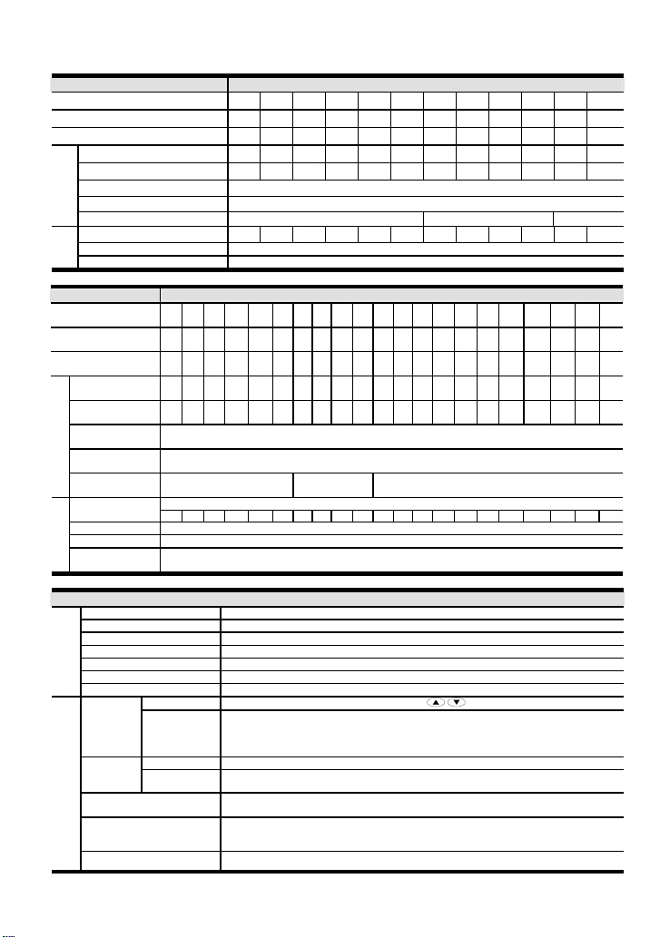
Specifications
±
Voltage Class 230V Class
Model Number VFD-XXXF23X 007 015 022 037 055 075 110 150 185 220 300 370
Max. Applicable Motor Output (kW) 0.75 1.5 2.2 3.7 5.5 7.5 11 15 18.5 22 30 37
Max. Applicable Motor Output (HP) 1.0 2.0 3.0 5.0 7.5 10 15 20 25 30 40 50
Rated Output Capacity (kVA) 1.9 2.5 4.2 6.5 9.5 12.5 18.3 24.7 28.6 34.3 45.7 55
Rated Output Current (A) 5.0 7.0 11 17 25 33 49 65 75 90 120 145
Maximum Output Voltage (V)
Rated Frequency (Hz)
Output Rating
Carrier Frequency (kHz) 4-10 3-9 2-6
Rated Input Current (A) 5.7 7.6 15.5 20.6 26 34 50 60 75 90 110 142
Rated Voltage 3-phase 180-264 V
Input
Rating
Frequency Tolerance 47 – 63 Hz
Voltage Class
Model Number
VFD-XXXF43X
Max. Applicable Motor
Output (kW)
Max. Applicable Motor
Output (hp)
Rated Output
Capacity (kVA)
Rated Output
Current (A)
Maximum Output
Voltage (V)
Output Frequency
Output Rating
(Hz)
Carrier Frequency
(kHz)
Current (A)
Rated Voltage 3-phase 342-528 V
Voltage Tolerance -15~+10% (342-528 V)
Frequency
Input Rating
Tolerance
Control System SPWM (Sinusoidal Pulse Width Modulation, carrier frequency 2-10kHz)
Output Frequency Resolution 0.01Hz
Torque Characteristics Including the auto-torque, auto-slip compensation; starting torque can be 150% at 1.0Hz
Overload Endurance 120% of rated current for 1 minute
Control
Accel/Decel Time 1-36000/0.1-3600.0/0.01-360.00 seconds (3 Independent settings for Accel/Decel Time)
V/f Pattern Adjustable V/f pattern
Characteristics
Stall Prevention Level 20 to 150%, Setting of Rated Current
Frequency
Setting
Setting
Signal
Multi-Function Input Signal
Multi-Function Output
Operating Characteristics
Indication
007 015 022 037 055 075 110 150 185 220 300 370 450 550 750 900 1100 1320 1600 1850 2200
0.75 1.5 2.2 3.7 5.5 7.5 11 15 18.5 22 30 37 45 55 75 90 110 132 160 185 220
1.0 2.0 3.0 5.0 7.5 10 15 20 25 30 40 50 60 75 100 125 150 175 215 250 300
2.3 3.2 4.2 6.5 10 14 18 25 29 34 46 56 69 84 114 137 168 198 236 281 350
2.7 4.2 5.5 8.5 13 18 24 32 38 45 60 73 91 110 150 180 220 260 310 370 460
4-10 3-9 2-6
3.2 4.3 5.9 11.2 14 19 25 32 39 49 60 73 91 120 160 160 200 240 300 380 400
General Specification
Keypad
External Signal
1 set of AVI analog voltage DC0-+10V/0-+5V, 2 sets of ACI analog current 0/4-20mA,
15 Multi-Function Inputs, RS-485 interface (MODBUS), External terminals UP/DOWN
Keypad Set by RUN, STOP and JOG Operation
External Signal Operation by FWD, REV, JOG and communication operation
Multi-step selection 0 to 15, Jog, accel/decel inhibit, first to forth accel/decel switches,
counter, external Base Block (NC, NO), JOG, auxiliary motor start/maintenance
AC Drive Operating, Frequency Attained, Desired Frequency Attained, Zero speed, Base
Block, Fault Indication, Local/Remote indication, and Auxiliary Motor Output
Analog Output Signal 2 sets of Analog frequency/current signal output
Proportional to Input Voltage
0.10-120.00Hz
460V Class
3-phase Proportional to Input Voltage
0.10-120.00Hz
3-phase Rated Input
5% (47~63Hz)
Setting by
Key
English-2
Page 3
General Specification
A
A
A
AVR, 2 kinds of S-Curve, Over-Voltage, Over-Current Stall Prevention, Fault Records,
Other Functions
Protection
Built-in Reactor
Built-in Brake Chopper 1~20HP
Cooling Methods Forced Fan-cooled
Installation Location Altitude 1,000 m or lower, keep from corrosive gasses, liquid and dust
Pollution Degree 2
Reverse inhibition, DC Brake, Momentary Power Loss restart, Auto torque and slip
compensation, PID Control, Parameter Lock/Reset, Frequency Limits, Adjustable Carrier
Self-testing, Over Voltage, Over Current, Under Voltage, Overload, Overheating, External
Frequency, 4 sets of Fan & Pump Control,
Fault, Electronic thermal, Ground Fault, Phase-loss
DC Reactor: 25~215HP
AC Reactor: 250~300HP
Ambient Temperature -10oC to 40oC Non-Condensing and not frozen
Storage/ Transportation
Temperature
Conditions
Enviromental
Ambient Humidity Below 90% RH (non-condensing)
Vibration 9.80665m/s2 (1G) less than 20Hz, 5.88m/s2 (0.6G) at 20 to 50Hz
Approvals
o
-20
C to 60oC
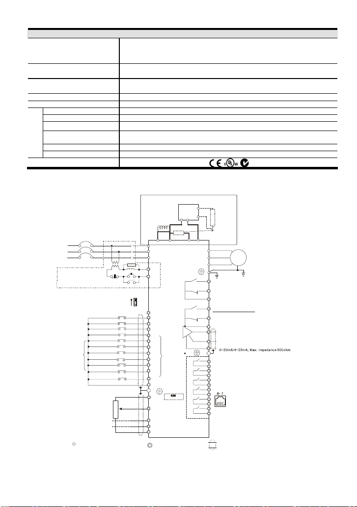
Basic Wiring Diagram
Users must connect wiring according to the following circuit diagram shown below.
For 230V series, 1-15 hp models
460V series, 1-20hp models
DC Reactor
(Optional)
OFF
3
2
1
ON
4~20mA
4~20mA
SA
Source
Jumper
MC
Sink
Sw1
+1
+2/B1
R/L1
S/L2
VFD-F
T/L3
RB1
RC1
+24V
FWD
REV
EF
MI1
MI2
Multi-
MI3
function
MI4
input
terminals
MI5
MI6
MI7
MI8
DCM
E
+10V
Sw2
Power supply
+10V 20mA
AVI
Master Frequency
0~10V/5V(47Kohm)
(250ohm)
ACI1
(250ohm)
ACI2
ACM
Control circuit terminals
English-3
NFB
R/L1
S/L2
T/L3
NFB
Recommended Ci rcuit
when power supp ly
is turned OFF b y a
fault output
Factory Setting: SINK Mode
Please refer to following
wiring for SINK mode and
SOURCE mode.
FWD/STOP
REV/STOP
E.F.
Multi-step1
Multi-step2
Multi-step3
Multi-step4
RESET
Factory
JOG
setting
Accel/Decel prohibit
1/2 Acce l/ Dec el swit ch
Digital Signal Comm on
*Don't apply the mains voltage
directly to above terminals.
5Kohm
nalog Signal Com mon
Main circuit (power) terminals
NOTE:Do not plug a Modem or telephone line to the RS-485 communication port, permanent damage may
result. Pins 1 & 2 are the power sources for the optional copy keypad and should not be used while using RS-
485 communication.
BR
0-10V0-5V
VFDB
PN
B1
B2
-
B2
U/T1
V/T2
W/T3
RA1
RB1
RC1
RA2
RB2
RC2
FM1
AFM2
ACM
RY00
Relay B.D.
(Optional)
Brake
Unit (Optional)
Brake
Resisto r
(Optional)
Multi-function indication
output contacts
Please refer to
Terminal Explanation
Multi-function Analog
output terminal
Factory setting: output frequency
0~10VDC/2mA
Factory setting: output current
E
nalog Signal Common
RA3
RC3
RA4
RC4
RA5
RC5
RA6
RC6
RA7
RC7
RA8
1: +EV 2: GND
RC8
4: SG+
6: for communication
Shielded leads & Cable
Please refer to following wiring
for other mode ls
Motor
IM
3~
RS-485
Serial communication interface
3: SG-
5:NC
Page 4
For 230V series, 20hp and above models
460V serie s, 25hp and above models
DC Reactor
(Optional)
Jumper
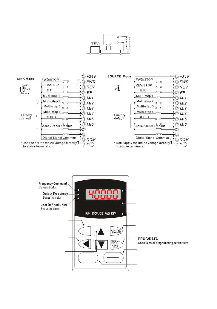
Wiring for SINK mode and SOURCE mode
VFDB
PN
Brake
Unit ( Optiona l)
B1
B2
Sink
Sw1
Source
Brake
Resistor
(Optional)
JOG
1/2 Accel/Decel switch
MI7
MI8
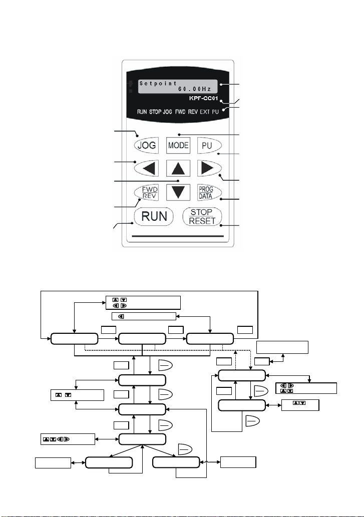
VFD-PU01
X Description of the Digital Keypad VFD-PU01
F
H
JOG
By pressing JOG key.
Initiat es jog ope ration .
moves cursor to the left
UP and DOWN Key
Sets the parameter
number and changes the
numerical data, such as
Master Frequency.
Left key
U
JOG
RUN
VFD-PU01
RESET
English-4
STOP
JOG
1/2 Accel/Decel switch
LED Display
Display frequency, current, voltage
and error, et c.
Part Number
Status Display
Display the driver's current status
MODE
C
hanges between different
display mode.
STOP/RESET
RUN key
MI7
MI8
Page 5
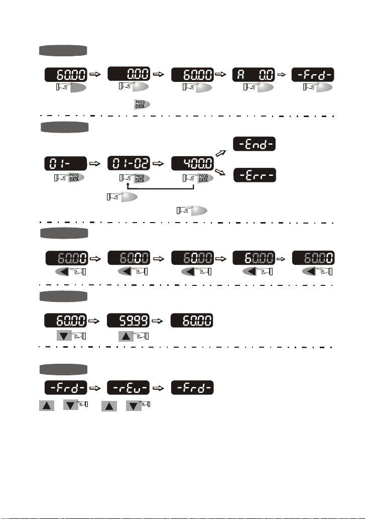
Y Operation steps of the Digital Keypad VFD-PU01
Selecting mode
START
F
H
U
F
H
U
MODE
In the selection mode, press
Note
:
Setting parameters
NOTE
:
To shift data
START
F
H
U
To modify data
START
F
H
U
F
H
U
MODE
F
H
U
to set the parameters.
F
H
U
MODE
F
H
U
F
H
U
F
H
U
move to previous display
MODE
F
H
U
F
H
U
MODE
F
H
U
F
H
U
Success to set parameter.
F
H
U
Input data error
to return the selecting mode.In the parameter setting mode, you can press
F
H
U
F
H
U
F
H
U
MODEMODE
GO START
Setting direction
F
H
U
or
F
H
U
or
F
H
U
English-5
Page 6
KPF-CC01
X Description of the Digital Keypad KPF-CC01
LCD Display
Indicates frequency, voltage, current, user
defined units, read, and s ave etc.
Model Number
Status Display
Display the driver current status.
's
JOG Operation key
Press this key to execute
the JOG frequency operation.
Left key
Moves the cursor left.
UP and DOWN key
Set the parameter number and
changes the numerical data, such
as Master Frequency.
FWD/REV Direction key
Sel ect FWD/REV operation
Start AC drive operation.
RUN key
Y KPF-CC01 Operation Flow Chart
KPF-CC01 Operation Flow Chart
Change Frequency Command
Shift Cursor
Select Multi-Function Display
6 0 . 0 0 H z
MODE
I n v a i l d D a t a
O u t p u t F r e q u e n c y
MODE
Group Description...
P x x – 0 0 =
MODE
Parameter Description...
P x x – x x = Value
MODE
Parameter Description...
P x x – x x = Value
S e t p o i n t
Change Number
Adjust Value
Program Error
0 . 0 0 H z
V a l u e A c c e p t e d
MODE
Change between different display mode.
Parameter Unit key
Switch the operation comm and source.
Right key
Moves the cursor right.
PROG/DATA
Used to enter programming parameters.
STOP/RESET
Stops AC drive operation or reset the drive
after fault occurred.
MODE
L o a d c u r r e n t
PROG
DATA
PROG
DATA
PROG
DATA
PROG
DATA
0 . 0 A m p
MODE
R e a d B l o c k 1
- E m p t y A d d r e s s -
MODE
C o p y t o K e y P a d ?
< B l o c k 1 > N o
Program Success
MODE
Copy Mode: Press MODE key
MODE
PROG
DATA
PROG
DATA
for about 2~3 seconds
Select Memory Address
Select Copy Function
Press Key to
confirm function
English-6
Page 7
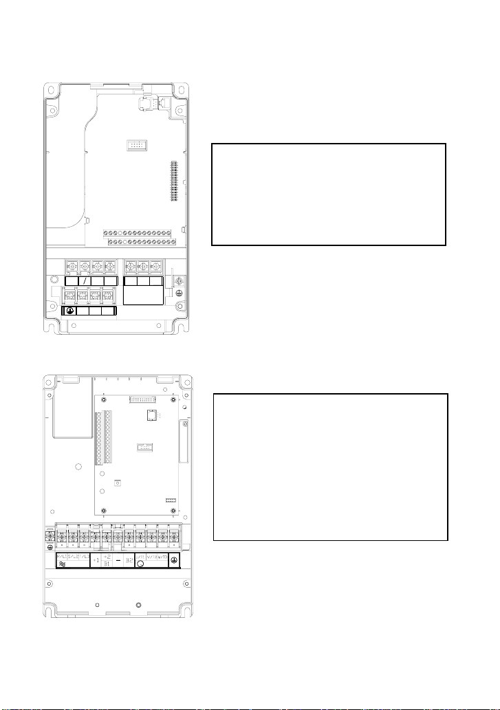
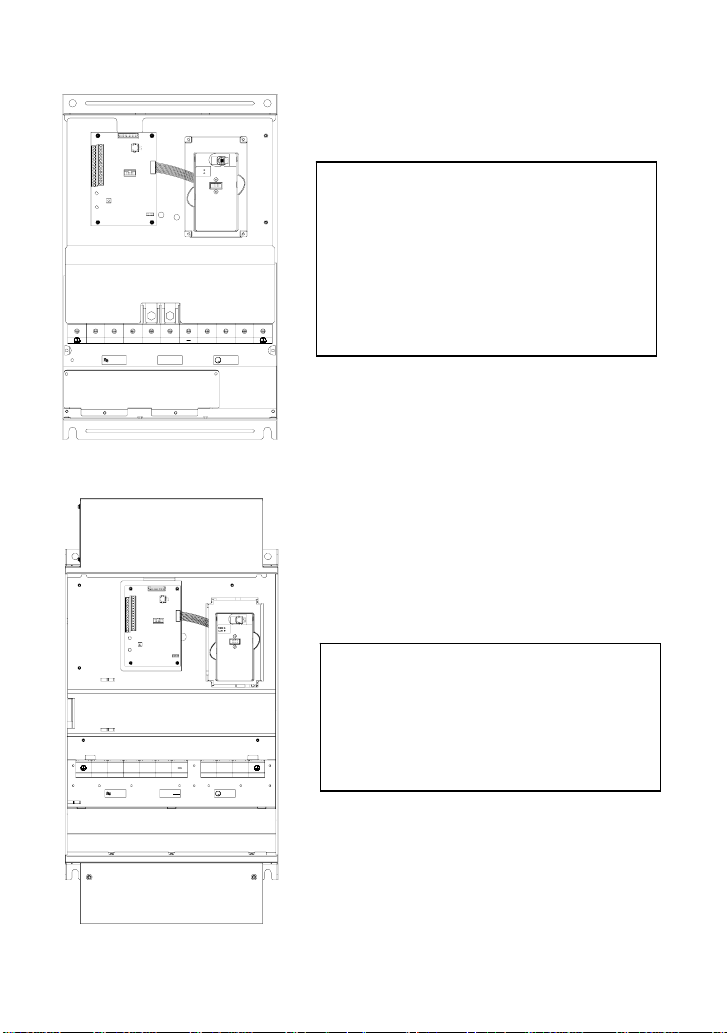
Power Terminals and Control Terminal
1HP to 5HP (VFD007F23A/43A, VFD015F23A/43A, VFD022F23A/43A, VFD037F23A/43A)
Control Terminal
Torque: 4Kgf-cm (3 in-lbf)
Wire: 12-24 AWG
Power Terminal
Torque: 18 kgf-cm (15.6 in-lbf)
Wire Gauge: 10-18 AWG
Wire Type: Stranded copper only, 75° C
+2
-
U/T1 V/T2 W/T3
2
B
+1
B
1
Screw Torque :
18Kgf-cm
Wire Gauge :
R/L1S/L2 T/L3
18~10AWG
7.5 HP to 20 HP (VFD055F23A/43B, VFD075F23A/43B, VFD110F23A/43A, VFD150F43A)
Control Terminal
Torque: 4Kgf-cm (3 in-lbf)
Wire: 12-24 AWG
Power Terminal
Torque: 30Kgf-cm (26 in-lbf)
Wire: 12-8 AWG
Wire Type: Stranded copper only, 75° C
NOTE: If wiring of the terminal utilizes the wire
with a 6AWG-diameter, it is thus necessary to use
the Recognized Ring Terminal to conduct a
proper wiring.
POWER
IM
MOTOR3
English-7
Page 8
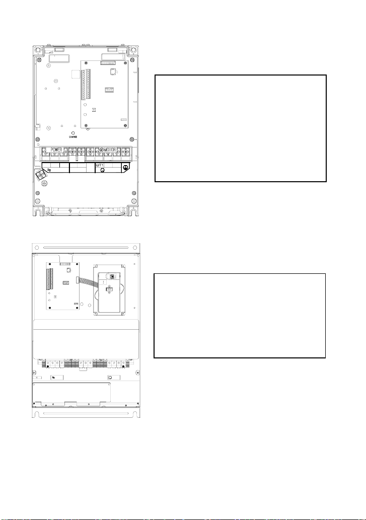
20 HP to 40 HP (VFD150F23A, VFD185F23A/43A, VFD220F23A/43A, VFD300F43A)
Control Terminal
Torque: 4Kgf-cm (3 in-lbf)
Wire: 12-24 AWG
Power Terminal
Torque: 30Kgf-cm (26 in-lbf)
Wire: 8-2 AWG
Wire Type: Stranded copper only, 75° C
NOTE: If wiring of the terminal utilizes the wire
R/L1
S/L2
POWER
+1
T/L3
+2
( )
+ DC DC
W/T3V/T2
-
IM
( )
-
MOTOR
3
with a 1AWG-diameter, it is thus necessary to use
the Recognized Ring Terminal to conduct a
proper wiring.
50 HP to 60 HP (VFD370F43A, VFD450F43A)
POWER
ALARM
Control Terminal
Torque: 4Kgf-cm (3 in-lbf)
Wire: 12-24 AWG
CHARGE
Power Terminal
Torque: 57kgf-cm (49.5 in-lbf) min.
Wire Gauge: VFD370F43A: 3AWG
Wire Type: Stranded copper only, 75° C
R/L1
S/L2 T/L3 U/T1 V/T2 2/T3
+1
-
+2
POWER
IM
MOTOR
3
VFD450F43A: 2AWG
English-8
Page 9
40 HP to 125 HP (VFD300F23A, VFD370F23A, VFD550F43A, VFD750F43A, VFD900F43C)
POWER
ALARM
Control Terminal
Torque: 4Kgf-cm (3 in-lbf)
CHARGE
Wire: 12-24 AWG
Power Terminal
Torque: 200kgf-cm (173 in-lbf)
Wire Gauge:
VFD300F23A, VFD550F43A: 1/0-4/0 AWG
VFD370F23A, VFD750F43A: 3/0-4/0 AWG,
VFD900F43C: 4/0 AWG
Wire Type: Stranded copper only, 75°C
POWER
Screw Torque:
(173in-lbf)
200kgf-cm
W/T3S/L2R/L1 T/L3 +2+1 U/T1 V/T2
IM
MOTOR
3
125HP (VFD900F43A)
+2S/L2R/L1 T/L3 +1 V/T2U/T1 W/T3
Screw Torque:
POWER
200kgf-cm
Control Terminal
Torque: 4Kgf-cm (3 in-lbf)
Wire: 12-24 AWG
Power Terminal
Torque: 200kgf-cm (173 in-lbf)
Wire Gauge: 4/0 AWG
IM
Wire Type: Stranded copper only, 75°C
MOTOR
3
English-9
Page 10
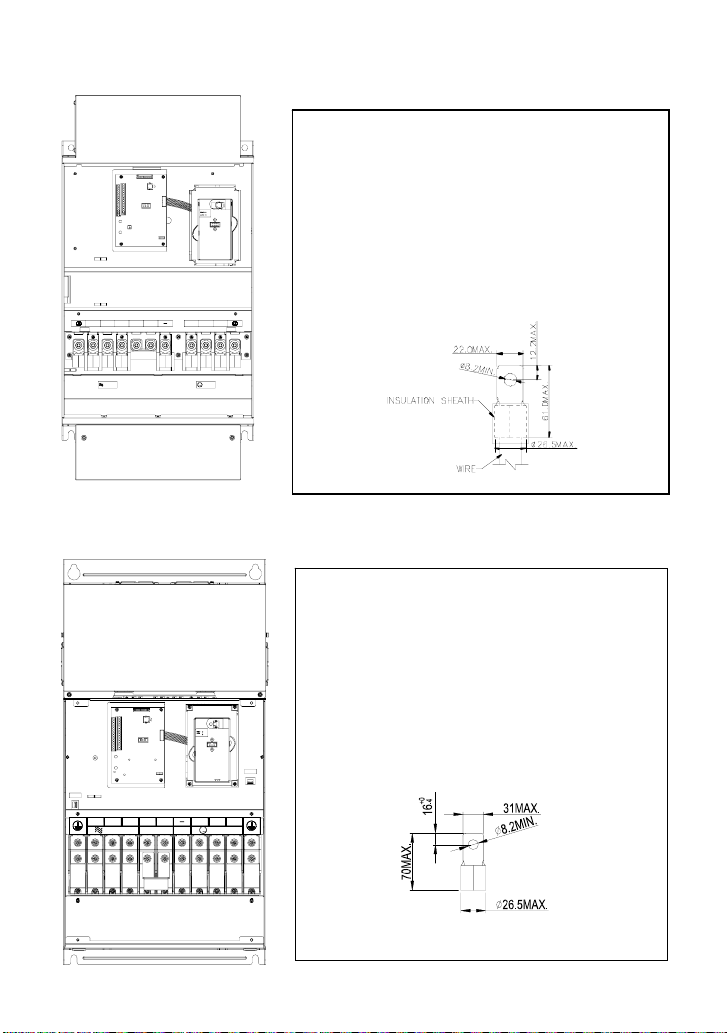
150HP (VFD1100F43A)
V/T2S/L2R/L1 +2+1T/L3 U/T1 W/T3
Control Terminal
Torque: 4Kgf-cm (3 in-lbf)
Wire: 12-24 AWG
Power Terminal
Torque: 80kgf-cm (69 in-lbf)
Wire Gauge: 300 MCM
Wire Type: Stranded copper only, 75°C
NOTE: It needs following additional terminal when
wiring, and add insulation sheath on position where
following figure shows.
POWER
IM
MOTOR
3
150 HP to 215 HP
(VFD1100F43C, VFD1320F43A, VFD1600F43A)
Control Terminal
Torque: 4Kgf-cm (3 in-lbf)
Wire: 12-24 AWG
Power Terminal
Torque: 300kgf-cm (260 in-lbf)
Wire Gauge: 1/0 AWG*2-300 MCM*2
Wire Type: Stranded copper only, 75°C
NOTE: It needs following additional terminal when
wiring. The additional terminal dimension should
comply with the following figure.
V/T2S/L2R/L1 +2T/L3 +1 U/T1 W/T3
IM
DC(+)
DC(-)
MOTOR
POWER
3
English-10
UNIT:mm
Page 11

250 HP to 300 HP
(VFD1850F43A, VFD2200F43A)
-
U/T1T/L3R/L1 S/L2
+
( )-
( )
POWER
DC + DC
Control Terminal
Torque: 4Kgf-cm (3 in-lbf)
Wire: 12-24 AWG
Power Terminal
Torque: 408kgf-cm (354 in-lbf)
Wire Gauge: 500 MCM (max)
Wire Type: Stranded copper only, 75°C
NOTE: It needs following additional terminal
when wiring, and add insulation sheath on
position where following figure shows.
W/T3V/T2
Terminal Explanations
Terminal Symbol
R/L1, S/L2, T/L3 AC line input terminals
U/T1, V/T2, W/T3 AC drive output terminals motor connections
+1,+2 Connections for DC Link Reactor (optional)
+2/B1~B2 Connections for Brake Resistor (optional)
+2~ -,+2/B1~ - Connections for External Brake Unit (VFDB series)
Earth Ground
Explanation of Terminal Function
English-11
Page 12

Control Terminals Explanations
Terminal
Symbols
Terminal Functions Factory Settings
FWD Forward-Stop command
REV Reverse-Stop command
EF External fault
MI1 Multi-function Input 1 Factory default: Multi-step speed command 1
MI2 Multi-function Input 2 Factory default: Multi-step speed command 2
MI3 Multi-function Input 3 Factory default: Multi-step speed command 3
MI4 Multi-function Input 4 Factory default: Multi-step speed command 4
MI5 Multi-function Input 5 Factory default: RESET
MI6 Multi-function Input 6 Factory default: JOG
MI7 Multi-function Input 7 Factory default: Accel/Decel prohibit
MI8 Multi-function Input 8 Factory default: Accel/Decel time switch 1
+24V DC Voltage Source (+24V, 20mA), used for source mode.
DCM Digital Signal Common
Used as common for digital inputs and used for
sink mode.
RA 1 Multi-function Relay1 output (N.O.) a
RB 1 Multi-function Relay1 output (N.C.) b
RC 1 Multi-function Relay1 common
RA 2 Multi-function Relay2 output (N.O.) a
1.5A(N.O.)/1A(N.C.) 240VAC
1.5A(N.O.)/1A(N.C.) 24VDC
Refer to Pr.03-00 to Pr.03-01
RB 2 Multi-function Relay2 output (N.C.) b
RC 2 Multi-function Relay2 common
+10V Potentiometer power source +10V 20mA
AVI Analog voltage Input
ACI 1/2 Analog current Input
0 to +10V correspond to Max. operation
frequency
4 to 20mA correspond to Max. operation
frequency
AFM 1 Analog frequency /current meter 1 0 to 10V correspond to Max. operation frequency
AFM 2 Analog frequency /current meter 2
4 to 20mA correspond to 2 times of output
current
ACM Analog control signal (common)
* Control signal wiring size: 18 AWG (0.75 mm2).
English-12
Page 13

SUMMARY OF PARAMETER SETTINGS
a: The parameter can be set during operation
Group 0 AC Drive Status Parameter
Parameter Functions Settings
00-00 Software Version Read only
00-01 AC Drive Status
Indication 1
00: No Fault occurred
01: oc (over current)
02: ov (over voltage)
03: oH (over temperature)
04: oL (overload)
05: oL1 (electronic thermal relay)
06: EF (external Fault)
07: occ (AC drive IGBT fault)
08: cF3 (CPU failure)
09: HPF (Hardware Protection Failure)
10: ocA (current exceed during Acceleration)
11: ocd (current exceed during Deceleration)
12: ocn (current exceed during Steady State)
13: GFF (Ground Fault)
14: Lv (Low voltage)
15: cF1 (input data abnormal)
16: cF2 (output data abnormal)
17: bb (Base Block)
18: oL2 (over load2)
19: Reserved
20: codE (software or password protection)
21: EF1 (external Emergency Stop)
22: PHL (phase loss)
23: Lc (Low Current)
24: Fbl (Feedback Loss)
25: Reserved
26: FAnP (Fan Power Fault)
27: FF1 (Fan 1 fault)
28: FF2 (Fan 2 fault)
29: FF3 (Fan 3 fault)
30: FF123 (Fan 1, 2, 3 fault)
31: FF12 (Fan 1, 2 fault)
32: FF13 (Fan 1, 3 fault)
33: FF23 (Fan 2, 3 fault)
34: Fv (Gate Drive Low Voltage Protect)
00-02 AC Drive Status
Indication 2
Bit 0~1: 00: Run led is off and stop led is on.
01: Run led is blink and stop led is on.
10: Run led is on and stop led is blink.
11: Run led is on and stop led is off.
Bit 2: 1: Jog on.
Bit 3~4: 00: Rev led is off and FWD led is on.
01: Rev led is blink and FWD led is on.
10: Rev led is on and FWD led is blink.
11: Rev led is on and FWD led is off.
Bit 5-7: Reserved
Bit 8: Master frequency source via
communication interface
Factory
Setting
Read
Read
Customer
English-13
Page 14

Parameter Functions Settings
Bit 9: Master frequency source via analog
Factory
Customer
Setting
Bit10: Running command via communication
interface
Bit11: Parameter locked
Bit12~15: Reserved
00-03 Frequency Setting Read only Read
00-04 Output Frequency Read only Read
00-05 Output Current Read only Read
00-06 DC-BUS Voltage Read only Read
00-07 Output Voltage Read only Read
00-08 Output Power Factor Read only Read
00-09 Output Power (kW) Read only Read
00-10 Feedback Signal
Read only Read
Actual Value
00-11 Feedback Signal (%) Read only Read
00-12 User Target Value
Read only Read
(Low bit) uL 0-99.99
00-13 User Target Value
Read only Read
(High bit) uH 0-9999
00-14 PLC time Read only Read
Group 1 Basic Parameter (Twice the value for 460V class)
Parameter Functions Settings
01-00 Maximum Output
50.00~120.00Hz 60.00
Factory
Setting
Customer
Frequency
01-01 Maximum Voltage
0.10~120.00 Hz 60.00
Frequency (Base
Frequency)
01-02 Maximum Output
Voltage
230V series: 0.1~255.0V
460V series: 0.2~510.0V
220.0
440.0
01-03 Mid-point Frequency 0.10~120 Hz 1.50
01-04 Mid-point Voltage 230V series: 0.1~255.0V
460V series: 0.2~510.0V
01-05 Minimum Output
0.10~20.00 Hz 1.50
5.5
11.0
Frequency
01-06 Minimum Output Voltage 230V series: 0.1~50.0V
460V series: 0.2V~100.0V
5.5
11.0
01-07 Upper Bound Frequency 0.00~120.00 Hz 60.00
01-08 Lower Bound Frequency 0.00~120.00 Hz 0.00
a01-09 Acceleration Time 1 0.1~3600.0 Sec 10.0/
60.0
a01-10 Deceleration Time 1 0.1~3600.0 Sec 10.0/
60.0
a01-11 Acceleration Time 2 0.1~3600.0 Sec 10.0/
60.0
a01-12 Deceleration Time 2 0.1~3600.0 Sec 10.0/
60.0
a01-13 Acceleration Time 3 0.1~3600.0 Sec 10.0/
60.0
English-14
Page 15

Parameter Functions Settings
Factory
Setting
Customer
a01-14 Deceleration Time 3 0.1~3600.0 Sec 10.0/
60.0
a01-15 Acceleration Time 4 0.1~3600.0 Sec 10.0/
60.0
a01-16 Deceleration Time 4 0.1~3600.0 Sec 10.0/
60.0
a01-17 JOG Acceleration Time 0.1~3600.0 Sec 10.0/
60.0
a01-18 JOG Deceleration Time 0.1~3600.0 Sec 10.0/
60.0
a01-19 JOG frequency 0.0 Hz~120.00 Hz 6.00
01-20 S Curve Delay Time in
0.00~2.50sec 0.00
Accel
01-21 S Curve Delay Time in
0.00~2.50sec 0.00
Decel
a01-22 Modulation Index 0.90~1.20 1.00
01-23 Accel/Decel Time Unit 00: Unit is 1 Sec
01
01: Unit is 0.1 Sec
02: Unit is 0.01 Sec
Group 2 Digital Output/Input Parameter
Parameter Functions Settings
a02-00 Source of Frequency
Command
00: via keypad
01: via analog input AVI
Factory
Customer
Setting
00
02: via analog input ACI1
03: via analog input ACI2
04: via RS485 serial communication
05: via External Reference
a02-01 Source of Operation
Command
00: Controlled by the digital keypad
01: Controlled by the external terminals,
00
keypad STOP enabled.
02: Controlled by external terminals,
keypad STOP disabled.
03: Controlled by the RS-485
communication interface, keypad
STOP enabled.
04: Controlled by the RS-485
communication interface, keypad
STOP disabled.
02-02 Stop Method 00:Stop = ramp to stop, E.F. (External
00
Fault) = coast to stop
01:Stop = coast to stop, E.F. = coast to
stop
02:Stop = ramp to stop, E.F. = ramp to
stop
03:Stop = coast to stop, E.F. = ramp to
stop
a02-03 PWM Carrier Frequency
Selections
1~10HP: 4000~10000Hz
15~30HP: 3000~9000Hz
≧40HP: 2000~6000Hz
9000Hz
6000Hz
4000Hz
English-15
Page 16

Parameter Functions Settings
02-04 Forward/Reverse
Enable
00: Forward enabled
01: Reverse disabled
02: Forward disabled
02-05 2-wire/3-wire Operation
Control Modes
00: 2-wire (#1), FWD/STOP, REV/STOP
01: 2-wire (#2), RUN/STOP, REV/FWD
02: 3-wire
02-06 Line Start Lockout 00: Disabled
01: Enabled
02-07 Loss of ACI Signal 00: Decelerate to 0Hz
01: E.F.
02: Continue operation by the last
frequency command
a02-08 Start-up Display
Selection
Bit0~1: 00 = F LED
01 = H LED
10 = U LED (special display)
11 = Fwd / Rev
Bit2: 0 = Fwd LED / 1 = Rev LED
Bit3~5: 000 = 1st 7-step
001 = 2nd 7-step
010 = 3rd 7-step
011 = 4th 7-step
100 = 5th 7-step
Bit6~7: Reserved
a02-09 Special Display 00: A displays output current of AC drive
01: U displays DC-Bus voltage of AC drive
02: E displays RMS of output voltage
03: P displays feedback Signal
04: PLC display auto procedure state
a02-10 User Defined Coefficient 0.01~160.00
a02-11 Flying Start 00: Disable
01: Enable (Dc brake disabled)
a02-12 Flying Start Frequency 00: Trace from master frequency
command
01: Trace from maximum setting
frequency 01-00
a02-13 Master Frequency
Memory Setting
00: Do not remember the last known
frequency
01: Remember the last known frequency
Group 3 Output Function Parameters
Parameter Functions Settings
03-00 Multi-function Output
terminal 1
03-01 Multi-function Output
terminal 2
03-02 Multi-function Output
terminal 3
03-03 Multi-function Output
terminal 4
03-04 Multi-function Output
terminal 5
00: No function
01: Motor No.1
02: Motor No.2
03: Motor No.3
04: Motor No.4
05: Motor No.5
06: Motor No.6
07: Motor No.7
08: Motor No.8
09: Auxiliary 1 output
Factory
Setting
00
00
01
01
00
00
1.00
00
00
01
Factory
Setting
00
00
00
00
00
Customer
Customer
English-16
Page 17

Parameter Functions Settings
03-05 Multi-function Output
terminal 6
03-06 Multi-function Output
terminal 7
03-07 Multi-function Output
terminal 8
10: Auxiliary 2 output
11: Auxiliary 3 output
12: Auxiliary 4 output
13: Auxiliary 5 output
14: Auxiliary 6 output
15: Auxiliary 7 output
16: Indication during operation
17: Master frequency attained
18: Zero Speed (including shutdown)
19: Over-torque
20: External Fault
21: Low voltage detection
22: Operation Mode indication
23: Fault indication
24: Master Frequency Attained 1
25: Master Frequency Attained 2
26: Over Temperature indication
27: Drive Ready
28: External Emergency Stop (EF1)
29: Software Brake Output
30: OL or OL1 Overload Warning
31: Dwell Indication (sleep)
32: Low Current Indication
33: PID Feedback Error Indication
34: PLC Program Running
35: PLC Program Step Completed
36: PLC Program Completed
37: PLC Program Operation Paused
03-08 Master Frequency
0.00~120.00 Hz 0.00
Attained 1
03-09 Master Frequency
0.00~120.00 Hz 0.00
Attained 2
03-10 Analog Output 1,
(AFM1) 0~10Vdc
03-11 Analog Output 2,
(AFM2) 0/4~ 20mA
a03-12 Analog Output Gain 1 01~200%
a03-13 Analog Output Gain 2 01~200%
03-14 Analog Output 2
Selection (AFM2
00: Output frequency
01: Output current
02: Output voltage
03: Frequency command
04: Power factor loading
00: 0~20mA
01: 4~20mA
Definition)
03-15 DC Fan Control 00: Fan runs on power up.
01: Fan begins upon a RUN command.
Fan stops 1 minute after a STOP
command.
02: Fan begins upon a RUN command.
Fan stops after a STOP command
03: Fan is controlled by temperature.
Approximately a 60°C temperature will
start the fan.
English-17
Factory
Customer
Setting
00
00
00
00
01
100
100
01
00
Page 18

Group 4 Input Function Parameters
Parameter Functions Settings
04-00 Multi-function Input
terminal 1
04-01 Multi-function Input
terminal 2
04-02 Multi-function Input
terminal 3
04-03 Multi-function Input
terminal 4
04-04 Multi-function Input
terminal 5
04-05 Multi-function Input
terminal 6
04-06 Multi-function Input
terminal 7
04-07 Multi-function Input
terminal 8
00: No function
01: Multi-Speed terminal 1
02: Multi-Speed terminal 2
03: Multi-Speed terminal 3
04: Multi-Speed terminal 4
05: Reset (NO)
06: Reset (NC)
07: Jog operation (JOG)
08: Accel/Decel disable
09: Accel/Decel 2 selection
10: Accel/Decel 3 selection
11: B.B. (NO) input
12: B.B. (NC) input
13: Increase Frequency
14: Decrease Frequency
15: Emergency stop (NO)
16: Emergency stop (NC)
Factory
Customer
Setting
01
02
03
04
05
07
08
09
17: AVI (open), ACI1 (close)
18: KEYPAD (open), EXT (close)
19: PID disable
20: Auxiliary 1 input
21: Auxiliary 2 input
22: Auxiliary 3 input
23: Auxiliary 4 input
24: Auxiliary 5 input
25: Auxiliary 6 input
26: Auxiliary 7 input
27: Motor No.1 output disable
28: Motor No.2 output disable
29: Motor No.3 output disable
30: Motor No.4 output disable
31: All motor output disable
32: Run PLC Program
33: Pause PLC Program
04-08 Digital Input Terminal
01~20 01
Response Time
04-09 AVI Minimum voltage 0.0~10.0V 0.0
04-10 AVI Maximum voltage 0.0~10.0V 10.0
04-11 AVI Minimum frequency
0.00~100.00% 0.00
(percentage of Pr.1-00)
04-12 AVI Maximum frequency
0.00~100.00% 100.00
(percentage of Pr.1-00)
04-13 ACI1 Minimum current 0.0~20.0mA 4.0
04-14 ACI1 Maximum current 0.0~20.0mA 20.0
04-15 ACI1 Minimum
0.0~100.0% 0.00
frequency (percentage
of Pr.1-00)
04-16 ACI1 Maximum
0.0~100.0% 100.00
frequency (percentage
of Pr.1-00)
04-17 ACI2 Minimum current 0.0~20.0mA 4.0
04-18 ACI2 Maximum current 0.0~20.0mA 20.0
English-18
Page 19

Parameter Functions Settings
04-19 ACI2 Minimum
0.00~100.00% 0.00
Factory
Setting
frequency (percentage
of Pr.1-00)
04-20 ACI2 Maximum
0.00~100.00% 100.00
frequency (percentage
of Pr.1-00)
04-21 Analog Input Delay AVI 0.00~10.00 Sec 0.50
04-22 Analog Input Delay
0.00~10.00 Sec 0.50
ACI1
04-23 Analog Input Delay
0.00~10.00 Sec 0.50
ACI2
04-24 Summation of External
Frequency Sources
00: No functions
01: AVI+ACI1
00
02: ACI1+ACI2
03: ACI2+AVI
04:Communication master frequency +AVI
05:Communication master frequency
+ACI1
06:Communication master frequency
+ACI2
Group 5 Multi-step Speed Frequency Parameters
Parameter Functions Settings
a05-00 1st Step Speed
0.00~120.00 Hz 0.00
Factory
Setting
Frequency
a05-01 2nd Step Speed
0.00~120.00 Hz 0.00
Frequency
a05-02 3rd Step Speed
0.00~120.00 Hz 0.00
Frequency
a05-03 4th Step Speed
0.00~120.00 Hz 0.00
Frequency
a05-04 5th Step Speed
0.00~120.00 Hz 0.00
Frequency
a05-05 6th Step Speed
0.00~120.00 Hz 0.00
Frequency
a05-06 7th Step Speed
0.00~120.00 Hz 0.00
Frequency
a05-07 8th Step Speed
0.00~120.00 Hz 0.00
Frequency
a05-08 9th Step Speed
0.00~120.00 Hz 0.00
Frequency
a05-09 10th Step Speed
0.00~120.00 Hz 0.00
Frequency
a05-10 11th Step Speed
0.00~120.00 Hz 0.00
Frequency
a05-11 12th Step Speed
0.00~120.00 Hz 0.00
Frequency
a05-12 13th Step Speed
0.00~120.00 Hz 0.00
Frequency
a05-13 14th Step Speed
0.00~120.00 Hz 0.00
Frequency
English-19
Customer
Customer
Page 20

Parameter Functions Settings
a05-14 15th Step Speed
0.00~120.00 Hz 0.00
Factory
Setting
Frequency
00: Disable PLC Operation
01: Execute one program cycle
02: Continuously execute program cycles
05-15 PLC Mode
03: Execute one program cycle step by
00
step
04: Continuously execute program cycles
step by step
05-16 PLC Forward/ Reverse
Motion
00 to 32767 (00: FWD 01: REV) 00
05-17 Time Duration Step 1 0.0 to 65500 sec 0.0
05-18 Time Duration Step 2 0.0 to 65500 sec 0.0
05-19 Time Duration Step 3 0.0 to 65500 sec 0.0
05-20 Time Duration Step 4 0.0 to 65500 sec 0.0
05-21 Time Duration Step 5 0.0 to 65500 sec 0.0
05-22 Time Duration Step 6 0.0 to 65500 sec 0.0
05-23 Time Duration Step 7 0.0 to 65500 sec 0.0
05-24 Time Duration Step 8 0.0 to 65500 Sec 0.0
05-25 Time Duration Step 9 0.0 to 65500 Sec 0.0
05-26 Time Duration Step 10 0.0 to 65500 Sec 0.0
05-27 Time Duration Step 11 0.0 to 65500 Sec 0.0
05-28 Time Duration Step 12 0.0 to 65500 Sec 0.0
05-29 Time Duration Step 13 0.0 to 65500 Sec 0.0
05-30 Time Duration Step 14 0.0 to 65500 Sec 0.0
05-31 Time Duration Step 15 0.0 to 65500 Sec 0.0
05-32 Time Unit Settings
00: 1 Sec
01: 0.1 Sec
00
Group 6 Protection Function Parameters (Twice the value for 460V class)
Parameter Functions Settings
06-00 Over-voltage Stall
Prevention
230V: 330.0~410.0VDC
460V: 660.0~820.0VDC
Factory
Setting
390.0
780.0
00: Disable
06-01 Over-current Stall
Prevention during
20~150%
00: Disable
120
Acceleration
06-02 Over-current Stall
Prevention during
20~150%
00: Disable
120
operation
Customer
Customer
English-20
Page 21

Parameter Functions Settings
06-03 Over-torque Detection
Selection
00: Over-torque detection disabled.
01: Over-torque detection enabled during
Factory
Setting
00
constant speed operation (OL2), and
operation continues.
02: Over-torque detection enabled during
constant speed operation (OL2), and
operation halted.
03: Over-torque detection enabled during
operation (OL2), and operation
continues.
04: Over-torque detection enabled during
operation (OL2), and operation halted.
06-04 Over-torque Detection
30~150% 110
Level
06-05 Over-torque Detection
0.1~60.0 Sec 0.1
Time
06-06 Electronic Thermal
Relay Selection
00: Operate disabled.
01: Operate with a standard motor.
02
02: Operate with a special motor.
06-07 Electronic Thermal
30~600 Sec 60
Characteristic
06-08 Low Current Detection
00~100% (00 disabled) 00
Level
06-09 Low Current Detection
0.1~ 3600.0 Sec 10.0
Time
06-10 Low Current Detection
Treatment
00: Warn and Ramp to stop
01: Warn and Coast to stop
01
02: Warn and keep operating
06-11 Present Fault Record 00
06-12 Second Most Recent
Fault Record
06-13 Third Most Recent Fault
Record
06-14 Fourth Recent Fault
Record
00: No Fault
01: Oc (over-current)
02: Ov (over-voltage)
03: OH (over temperature)
04: OL (over load)
05: oL1 (over load 1)
06: EF (external fault)
07: Occ (IGBT module is abnormal)
00
00
00
08: cF3 (driver’s internal circuitry
abnormal)
09: HPF (hardware protection failure)
10: OcA (over-current during acceleration)
11: Ocd (over-current during deceleration)
12: Ocn (over-current during steady state
operation)
13: GFF (Ground Fault)
14: Lv (Low voltage)
15: cF1 (EEPROM WRITE failure)
16: cF2 (EEPROM READ failure)
17: bb (Base block)
18: OL2 (over load2)
19: Reserved
20: Code (software/password protection)
21: EF1 (Emergency stop)
22: PHL (phase-loss)
Customer
English-21
Page 22

Parameter Functions Settings
23: Lc (Low Current)
Factory
Setting
24: Fbl (Feedback Loss)
25: Reserved
26: FAnP (Fan Power Fault)
27: FF1 (Fan 1 fault)
28: FF2 (Fan 2 fault)
29: FF3 (Fan 3 fault)
30: FF123 (Fan 1, 2, 3 fault)
31: FF12 (Fan 1, 2 fault)
32: FF13 (Fan 1, 3 fault)
33: FF23 (Fan 2, 3 fault)
34: Fv (Gate Drive Low Voltage Protect)
06-15 Parameter Reset 00~65535
00
09: Reset parameters (50Hz, 220/380)
10: Reset parameters (60Hz, 220/440)
06-16 Parameter Protection
00~65535 00
Password Input
06-17 Parameter Protection
Password Setting
00~65535
00: No password protection
00
Group 7 AC Drive and Motor Parameters
Parameter Functions Settings
07-00 Identity Code of AC
Display by model type ##
Factory
Setting
Drive
07-01 Rated Current of AC
Display by model type ##
Drive
a07-02 Full-load Current of
30~120% 100%
Motor
a07-03 No-load Current of
1~99% 30%
Motor
a07-04 Auto Slip Compensation
0.0~3.0 0.0
Gain
07-05 Rated Slip Frequency of
0.00~20.00Hz 0.00
Motor
a07-06 Auto Torque
0.0~10.0 0.0
Compensation Gain
a07-07 Torque Compensation
0.0~10.0 0.0
Gain by Manually
07-08 Calculate Total Running
00 to 1439 Min 00
Time of the Motor (Min)
07-09 Calculate Total Running
00 to 65535 Day 00
Time of the Motor (Day)
Group 8 Special Parameters (Twice the value for 460V class)
Parameter Functions Settings
Factory
Setting
08-00 DC Brake Current Level 00~100% 00
08-01 DC Brake Time during
0.0~60.0 Sec 0.0
Start-up
Customer
Customer
Customer
English-22
Page 23

Parameter Functions Settings
08-02 DC Brake Time during
0.00~60.00 Sec 0.0
Factory
Setting
Stopping
08-03 Start-point for DC Brake 0.00~120.00 Hz 0.00
08-04 Momentary Power Loss
Operation Selection
00: Disable
01: Trace from top downward
00
02: Trace from bottom upward
08-05 Maximum Allowable
Power Loss Time
0.1~5.0 Sec 2.0
08-06 Speed Search Time 0.1~5.0 Sec 0.5
08-07 Maximum Speed
30~150% 110
Search Current
08-08 BB speed search
method
08-09 Auto Restart Times after
00: Trace from top downward
00
01: Trace from bottom upward
00~10 00
Fault
08-10 Auto Restart Time after
00 to 60000 sec 600
Fault
08-11 Operation Frequency
0.00~120.00 Hz 0.00
Inhibition 1 UP
08-12 Operation Frequency
1 DOWN
Inhibition
08-13 Operation Frequency
0.00~120.00 Hz 0.00
0.00~120.00 Hz 0.00
Inhibition 2 UP
08-14 Operation Frequency
2 DOWN
Inhibition
08-15 Operation Frequency
0.00~120.00 Hz 0.00
0.00~120.00 Hz 0.00
Inhibition 3 UP
08-16 Operation Frequency
3 DOWN
Inhibition
08-17 Automatic Energy-
saving
08-18 Automatic Voltage
Regulation (AVR)
0.00~120.00 Hz 0.00
00: Energy-saving operation disabled
00
01: Energy-saving operation enabled
00: AVR function enabled
00
01: AVR function disabled
02: AVR function disabled for deceleration
a08-19 Software Setting of the
Brake Level
(the action level of the
230V: 370~410VDC
460V: 740~820VDC
00:Disable
380.0
760.0
brake resistor)
a08-20 Vibration Compensation
00~1000 00
Factor
Group 9 Communication Parameters
Parameter Functions Settings
a09-00 Communication Address 01-254
Factory
Setting
01
00:Disable
a09-01 Transmission Speed
(Baud Rate)
00: Baud rate 4800
01: Baud rate 9600
01
02: Baud rate 19200
03: Baud rate 38400
Customer
Customer
English-23
Page 24

Parameter Functions Settings
a09-02 Transmission Fault
Treatment
00: Warn and keep operating
01: Warn and RAMP to stop
02: Warn and COAST to stop
03: No warning and no display
09-03 Over Time Detection
during Transmission
00: Disable
01: Enable
09-04 Communication Format 00: 7-bit for ASCII
01: 8-bit for ASCII
02: 8-bit for RTU
09-05 Even/Odd Parity and
Stopping Parity Setting
00: None parity + 2 stop bit
01: Even parity + 2 stop bit
02: Odd parity + 2 stop bit
03: None parity + 1 stop bit
04: Even parity + 1 stop bit
05: Odd parity + 1 stop bit
a09-06 Communication
Operation Command 1
Bit0~1: 00: Disable
01: Stop
10: Start-up
11: JOG start-up
Bit2~3: Reserved
Bit4~5: 00: No function
01: FWD command
10: REV command
11: Change direction command
Bit6~7: 00: 1
st
step accel/decel speed
nd
01: 2
step accel/decel speed
rd
step accel/decel speed
10: 3
th
step accel/decel speed
11: 4
Bit8~11: 0000: Master speed
0001: 1st step speed
0010: 2nd step speed
0011: 3rd step speed
0100: 4th step speed
0101: 5th step speed
0110: 6th step speed
0111: 7th step speed
1000: 8th step speed
1001: 9th step speed
1010: 10th step speed
1011: 11th step speed
1100: 12th step speed
1101: 13th step speed
1110: 14th step speed
1111: 15th step speed
Bit12: Select Bit6~11 function
Bit13~15 Reserved
a09-07 Communication
0~120.00Hz 60.00
Frequency Setting
a09-08 Communication
Operation Command 2
Bit0: 1: EF ON
Bit1: 1: Reset
Bit2: 0: BB OFF, 1: BB ON
Bit3~15: Reserved
English-24
Factory
Customer
Setting
03
00
00
00
00
00
Page 25

Group 10 PID Controls
Parameter Functions Settings
10-00 Input Terminal for PID
Feedback
00: No function
01: Input via AVI
Factory
Setting
00
02: Input via ACI1
03: Input via ACI2
04: Input via External Reference
10-01 PID Control Detection
0.0-6550.0 1000.0
Signal Reference
10-02 PID Feedback Control
Method
00: Negative feedback control
01: Positive feedback control
00
10-03 Proportional Gain (P) 0.0~10.0 1.0
10-04 Integral Time (I) 0.00~100.00 Sec 1.00
10-05 Differential Time (D) 0.00~1.00 Sec 0.00
10-06 Upper Bound for
00~200% 100
Integral Control
10-07 Primary Low Pass Filter
0.0~2.5 Sec 0.0
Time
10-08 PID Feedback Signal
0.0~6550.0 600.0
Range
10-09 PID Feedback Signal
Fault Treatment Time
a10-10 PID Feedback Signal
Fault Treatment
0. 0~3600.0 Sec
0.0: Disable
00: Warn and RAMP stop
01: Warn and COAST stop
0.0
01
02: Warn and keep operating
a10-11 PID Minimum Output
Frequency
0: By PID controller
1: By AC drive
01
Group 11 Fan and Pump Control Parameters
Parameter Functions Settings
11-00 V/f Curve Selection 00: Determined by group 01
Factory
Setting
00
01: 1.5 power curve
02: 1.7 power curve
03: 2 power curve
04: 3 power curve
11-01 Circulative Control 00: No function
00
01: Time circulation (by time)
02: Fixed amount circulation (by PID)
03: Fixed amount control (an AC drive
runs with 4 motors)
11-02 Multiple Motors Control 01~04 01
11-03 Time Circulation Time
00~65500 Min 00
Setting
11-04 Motor Switch Delay
0.0~3600.0 sec 1.0
Time
11-05 Motor Switch Delay
0.0~3600.0 sec 10.0
Time during Fixed
Amount Circulation
Customer
Customer
English-25
Page 26

Parameter Functions Settings
11-06 Motor Switch Frequency
during Fixed Amount
Circulation
11-07 Enter Sleep Process
Time
11-08 Sleep Frequency of
Sleep Process
11-09 Wake Up Frequency of
Sleep Process
11-10 Treatment of Fixed
Amount Circulation
Malfunction
11-11 Stop Frequency of
Auxiliary Motor
0.00 to 120.00 Hz 60.00
0.0~3600.0sec
0.0: Sleep function disable
0.00 to 11-09 (Wake up Frequency) 0.0
0.00 to 120.0Hz 0.0
00: Turn off all motors
01: Turn off AC drive
0.00~120.00Hz 0.00
Fault Codes
Fault
Fault Descriptions Corrective Actions
Name
Software
protection failure
GFF hardware
error
CC (Current
Clamp)
OC hardware error Return to the factory.
OV hardware error Return t o the f actory.
OH hardware error Return to the factory.
Over current
Abnormal increase
in current.
Over voltage
The DC bus voltage
has exceeded its
maximum allowable
value.
Return to the factory.
Return to the factory.
Return to the factory.
1. Check whether the motors horsepower corresponds to the
AC drive output power.
2. Check the wiring connections between the AC drive and
motor for possible short circuits.
3. Increase the Acceleration time.
4. Check for possible excessive loading conditions at the motor.
5. If there are any abnormal conditions when operating the AC
drive after short-circuit being re move d, it sh oul d be s ent back
to manufacturer.
1. Check whether the input voltage falls within th e rated AC
drive input voltage.
2. Ch eck for possi ble volt age tra nsients.
3. B us over-vo ltage may a lso be caused by motor regene ration.
Either increase the decel t ime or a dd a n opt io nal br ake
resistor.
4. Check whether the required brake power is wit hin t he
specified limits.
Factory
Customer
Setting
0.0
00
English-26
Page 27

Fault
Fault Descriptions Corrective Actions
Name
1. Ensure that the ambient temperature falls within the speci fi ed
Overheating
Heat sink
temperature too
high
temperature range.
2. Make sure that the ventilat ion h oles are not obstr ucted.
3. Remove any foreign objects from the heatsinks and check for
possible dirty heat sink fins.
4. Check the fan and clean it.
5. Provide enough spacing for adequate ventilation.
Low voltage
The AC motor drive
detects that the DC
bus voltage has
fallen below its
minimum value.
Overload
The AC motor drive
detects excessive
drive output current.
1. Check whether the input voltage falls wit hin the AC mo tor
drive rated input voltage rang e.
2. Check whether the motor has sudden load.
3. Check for correct wiring of input power to R-S-T (for 3-phase
models) without phase loss.
1. Check whether the motor is overloaded.
2. Reduce torque compensation setting in Pr.7-02.
3. Take the next higher power AC motor drive model.
NOTE: The AC motor drive can withstand up to 150% of the
rated current for a maximum of 60 seconds.
1. Check for possible motor overload.
Overload 1
Internal electronic
overload trip
2. Check electronic thermal overload setting.
3. Use a higher power motor.
4. Reduce the current level so that the drive output current does
not exceed the value set by the Motor Rated Current Pr.7-00.
Overload 2
Motor overload.
1. Reduce the motor load.
2. Adjust the over-torque detection setting to an appropriate
setting. (Pr. 06-03 to Pr. 06-05)
1. Input EF (N.O.) on external terminal is closed to GND. Output
External Fault
U, V, W will be turned off.
2. Give RESET command after fault has been cleare d.
Communication
error
Over-current
during
acceleration
Over-current
during
deceleration
1. Check the connection between the AC drive and computer
for loose wires.
2. Check if the communication protocol is pr op erl y set.
1. Short -circuit at motor output: Check for possible poor
insulation at the output lines.
2. Torque boost too high: Decrease the torque compensation
setting in Pr.7-02.
3. Acceleration Time too short: Increase the Acceleration Time.
4. AC motor drive output power is too small: Replace the AC
motor drive with the next higher power model.
1. Short -circuit at motor output: Check for possible poor
insulation at the output line.
2. Deceleration Time too short: Increase the Deceleration Time.
3. AC motor drive output power is too small: Replace the AC
motor drive with the next higher power model.
English-27
Page 28

Fault
Fault Descriptions Corrective Actions
Name
1. Short -circuit at motor output: Check for possible poor
Over-current
during steady state
operation
Emergency stop
Internal EEPROM
can not be
programmed.
Internal EEPROM
can not be read.
insulation at the output line.
2. Sudden increase in motor loading: Check for possible moto r
stall.
3. AC motor drive output power is too small: Replace the AC
motor drive with the next higher power model.
1. When the multi-funct ion i nput t erminals MI1 to MI6 are set to
emergency stop, the AC motor drive stops output U, V, W
and the motor coasts to stop.
2. Press RESET after fault has been clea red.
1. Turn off the power.
2. Check whether the input voltage falls within the rated AC
drive input voltage.
3. Turn on the power.
1. Check the connections between the main control board and
the power board
2. Reset the drive to the factory settings.
U-phase error Return to the factory.
V-phase error Return to the factory.
W-phase error Return to the factory.
OV or LV Return to the factory.
Isum error Return to the factory.
OH error Return to the factory.
1. When the external input terminal (B.B) is active, the AC
External Base
Block.
Auto accel/decel
failure
Ground fault
Analog feedback
error or ACI open
circuit
Fan Power Fault
(150~300HP)
Fan 1 fault
(150~300HP)
motor drive output will be turned off.
2. Deactivate the external input terminal (B.B) to operate the AC
motor drive again.
1. Check if the motor is suitable for operation by AC motor
drive.
2. Check if the regenerative energy is too large.
3. Load may have changed suddenly.
When (one of) the output termina l(s ) is gr ound ed, sh ort c irc uit
current is more than 50% of AC motor drive rated current, the AC
motor drive power module may be damaged.
NOTE: The shor t ci r cuit protection is pr ovi d e d for AC m ot or
drive protection, not for protection of the user.
1. Check whether the IGBT power module is damaged.
2. Check for possible poor insulation at the output line.
1. Check parameter settings and wiring of Analog feedback
(Pr.10-00).
2. Check for possible fault between system response time and
the feedback signal detection t i me (P r. 10-0 8).
Return to the factory.
Remove any foreign objects on the heatsinks and check for
possible dirty heat sink fins.
English-28
Page 29

Fault
Fault Descriptions Corrective Actions
Name
Fan 2 fault
(150~300HP)
Fan 3 fault
(150~300HP)
Fan 1, 2, 3 fault
(150~300HP)
Fan 1, 2 fault
(150~300HP)
Fan 1, 3 fault
(150~300HP)
Fan 2, 3 fault
(150~300HP)
Gate drive low
voltage protect
Dimensions are in mm [inch]
A
D
Remove any foreign objects on the heatsinks and check for
possible dirty heat sink fins.
Remove any foreign objects on the heatsinks and check for
possible dirty heat sink fins.
Remove any foreign objects on the heatsinks and check for
possible dirty heat sink fins.
Remove any foreign objects on the heatsinks and check for
possible dirty heat sink fins.
Remove any foreign objects on the heatsinks and check for
possible dirty heat sink fins.
Remove any foreign objects on the heatsinks and check for
possible dirty heat sink fins.
Return to the factory.
F
E
B
C
Model Name A B C D E F
007F23A/43A, 015F23A/43A,
022F23A/43A, 037F23A/43A
055F23A/43B, 075F23A/43B,
110F23A/43A, 150F43A
150F23A, 185F23A/43A,
220F23A/43A, 300F43A
150.0
[5.91]
200.0
[7.88]
250.0
[9.84]
260.0
[10.24]
323.0
[12.72]
403.8
[15.90]
English-29
160.2
[6.31]
183.2
[7.22]
205.4
[8.08]
135.0
[5.32]
185.6
[7.31]
226.0
[8.90]
244.3
[9.63]
303.0
[11.93]
384.0
[15.12]
6.5
[0.26]
7.0
[0.28]
10.0
[0.39]
Page 30

A
D
B
E
C
Model Name A B C D E F
370.0
370F43A, 450F43A, 550F43A
300F23A, 370F23A, 750F43A,
900F43C
[14.57]
370.0
[14.57]
589.0
[23.19]
595.0
[23.43]
260.0
[10.24]
260.0
[10.24]
335.0
[13.19]
335.0
[13.19]
560.0
[22.05]
560.0
[22.05]
13.0
[0.51]
13.0
[0.51]
A
D C
F
B
E
G
Model Name A B C D E F G
900F43A,
1100F43A
425.0
[16.73]
850.0
[33.46]
264.0
[10.39]
English-30
385.0
[15.16]
631.0
[24.84]
13.0
[0.51]
280.0
[11.02]
Page 31

F
H
U
VFD-PU01
FWD
STOP
JOG RE V
RUN
MODE
JOG
PROG
DATA
STOP
RUN
RESET
Model Name A B C D E F G
1100F43C,
1320F43A,
1600F43A
425.0
[16.73]
850.0
[33.46]
264.0
[10.39]
381.0
[15.00]
819.5
[32.26]
6.5
[0.26]
764.0
[30.08]
Model Name A B C D E F G H
1850F43A,
2200F43A
547.0
[21.54]
1150.0
[45.28]
360.0
[14.17]
480.0
[18.90]
1119.0
[44.06]
6.5
[0.26]
1072.6
[42.23]
English-31
1357.6
[53.45]
 Loading...