

Page 1
Industrial Automation Headquarters
1 4 E E
Delta Electronics, Inc.
Taoyuan Technology Center
No.18, Xinglong Rd., Taoyuan City,
Taoyuan County 33068, Taiwan
TEL: 886-3-362-6301 / FAX: 886-3-371-6301
Asia
Delta Electronics (Jiangsu) Ltd.
Wujiang Plant 3
1688 Jiangxing East Road,
Wujiang Economic Development Zone
Wujiang City, Jiang Su Province,
People's Republic of China (Post code: 215200)
TEL: 86-512-6340-3008 / FAX: 86-769-6340-7290
Delta Greentech (China) Co., Ltd.
238 Min-Xia Road, Pudong District,
ShangHai, P.R.C.
Post code : 201209
TEL: 86-21-58635678 / FAX: 86-21-58630003
Delta Electronics (Japan), Inc.
Tokyo Office
2-1-14 Minato-ku Shibadaimon,
Tokyo 105-0012, Japan
TEL: 81-3-5733-1111 / FAX: 81-3-5733-1211
Delta Electronics (Korea), Inc.
1511, Byucksan Digital Valley 6-cha, Gasan-dong,
Geumcheon-gu, Seoul, Korea, 153-704
TEL: 82-2-515-5303 / FAX: 82-2-515-5302
Delta Electronics Int’l (S) Pte Ltd
4 Kaki Bukit Ave 1, #05-05, Singapore 417939
TEL: 65-6747-5155 / FAX: 65-6744-9228
Delta Electronics (India) Pvt. Ltd.
Plot No 43 Sector 35, HSIIDC
Gurgaon, PIN 122001, Haryana, India
TEL : 91-124-4874900 / FAX : 91-124-4874945
Americas
Delta Products Corporation (USA)
Raleigh Office
P.O. Box 12173,5101 Davis Drive,
Research Triangle Park, NC 27709, U.S.A.
TEL: 1-919-767-3800 / FAX: 1-919-767-8080
Delta Greentech (Brasil) S.A
Sao Paulo Office
Rua Itapeva, 26 - 3° andar Edificio Itapeva One-Bela Vista
01332-000-São Paulo-SP-Brazil
TEL: +55 11 3568-3855 / FAX: +55 11 3568-3865
Europe
Deltronics (The Netherlands) B.V.
Eindhoven Office
De Witbogt 20, 5652 AG Eindhoven, The Netherlands
TEL: +31-(0)40-8003800 / FAX: +31-(0)40-8003898
5011640614
2016-05-16
Sensorless Vector Control Compact Drive VFD-E Series User Manual
Sensorless Vector
Control Compact Drive
VFD-E Series User Manual
*We reserve the right to change the information in this catalogue without prior notice.
ww w.del ta ww.co m
Page 2

Preface
Thank you for choosing DELTA’s high-performance VFD-E Series. The VFD-E Series is
manufactured with high-quality components and materials and incorporate the latest microprocessor
technology available.
This manual is to be used for the installation, parameter setting, troubleshooting, and daily
maintenance of the AC motor drive. To guarantee safe operation of the equipment, read the following
safety guidelines before connecting power to the AC motor drive. Keep this operating manual at hand
and distribute to all users for reference.
To ensure the safety of operators and equipment, only qualified personnel familiar with AC motor
drive are to do installation, start-up and maintenance. Always read this manual thoroughly before
using VFD-E series AC Motor Drive, especially the WARNING, DANGER and CAUTION notes.
Failure to comply may result in personal injury and equipment damage. If you have any questions,
please contact your dealer.
For Drive Board version 1.23 & Control Board version 2.23.
PLEASE READ PRIOR TO INSTALLATION FOR SAFETY.
DANGER!
1. AC input power must be disconnected before any wiring to the AC motor drive is made.
2. A charge may still remain in the DC-link capacitors with hazardous voltages, even if the power
has been turned off. To prevent personal injury, please ensure that power has turned off before
opening the AC motor drive and wait ten minutes for the capacitors to discharge to safe voltage
levels.
3. Never reassemble internal components or wiring.
4. The AC motor drive may be destroyed beyond repair if incorrect cables are connected to the
input/output terminals. Never connect the AC motor drive output terminals U/T1, V/T2, and W/T3
directly to the AC mains circuit power supply.
5. Ground the VFD-E using the ground terminal. The grounding method must comply with the laws
of the country where the AC motor drive is to be installed. Refer to the Basic Wiring Diagram.
6. VFD-E series is used only to control variable speed of 3-phase induction motors, NOT for
1-phase motors or other purpose.
7. VFD-E series shall NOT be used for life support equipment or any life safety situation.
I
Page 3

WARNING!
1. DO NOT use Hi-pot test for internal components. The semi-conductor used in AC motor drive
easily damage by high-voltage.
2. There are highly sensitive MOS components on the printed circuit boards. These components
are especially sensitive to static electricity. To prevent damage to these components, do not
touch these components or the circuit boards with metal objects or your bare hands.
3. Only qualified persons are allowed to install, wire and maintain AC motor drives.
CAUTION!
1. Some parameters settings can cause the motor to run immediately after applying power.
2. DO NOT install the AC motor drive in a place subjected to high temperature, direct sunlight, high
humidity, excessive vibration, corrosive gases or liquids, or airborne dust or metallic particles.
3. Only use AC motor drives within specification. Failure to comply may result in fire, explosion or
electric shock.
4. To prevent personal injury, please keep children and unqualified people away from the
equipment.
5. When the motor cable between AC motor drive and mo tor is too long, the layer insulation of the
motor may be damaged. Please use a frequency inverter duty motor or add a n AC outpu t reactor
to prevent damage to the motor. Refer to appendix B Reactor for details.
6. The rated voltage for AC motor drive must be 240V ( 480V for 460V models) and the short
circuit must be 5000A RMS (10000A RMS for the 40hp (30kW) models).
DeviceNet is a registered trademark of the Open Dev iceNet Vendor Association, Inc. Lonwork is a
registered trademark of Echelon Corporation. Profibus is a registered trademark of Profibus
International. CANopen is a registered trademark of CAN in Automation (CiA). Other trademarks
belong to their respective owners.
II
Page 4

Table of Contents
Chapter 1 Introduction
1.1 Receiving and Inspection………….…….……….……….……….…….1-2
1.2 Preparation for Installation and Wiring.……….………….…………...1-11
1.3 Dimensions………….……….……….…….………..……………….….1-17
Chapter 2 Installation and Wiring
2.1 Wiring………….……….……….……….………………….….2-3
2.2 External Wiring………….……….………….……….…………..….2-13
2.3 Main Circuit………….……….………….……….………….......….2-14
2.4 Control Terminals………….……….….………..………………..….2-19
Chapter 3 Keypad and Start up
3.1 Keypad………….……….……….……….……….……………...........….3-1
3.2 Operation Method………….……….……….……….……….…….…….3-2
3.3 Trial Run………….……….……….……….……….……………........….3-3
Chapter 4 Parameters
4.1 Summary of Parameter Settings………….….……….………....….4-2
4.2 Parameter Settings for Applications………….….……….…..…...4-37
4.3 Description of Parameter Settings………….………….……...….4-42
4.4 Different Parameters for VFD*E*C Models………….….……….4-172
Chapter 5 Troubleshooting
5.1 Over Current (OC) …………..……….…….…………..……….….5-1
5.2 Ground Fault………….………….….…………….……………....….5-2
5.3 Over Voltage (OV) ………….………….……….……….………..….5-2
5.4 Low Voltage (Lv) ………….…………. .…….……….…………….5-3
III
Page 5

5.5 Over Heat (OH) ………….…………. .…………….……………...5-4
5.6 Overload………….……….………….……..……………..........….5-4
5.7 Keypad Display is Abnormal………….……….……….……...….5-5
5.8 Phase Loss (PHL) ………….……….……….………….…….....….5-5
5.9 Motor cannot Run………….……….……….…….…….………...….5-6
5.10 Motor Speed cannot be Changed………….….….….……….……5-7
5.11 Motor Stalls during Acceleration………….….……….……....….5-8
5.12 The Motor does not Run as Expected……….……………..….….5-8
5.13 Electromagnetic/Induction Noise………….….…….….……..….5-9
5.14 Environmental Condition………….……….….……….……....….5-9
5.15 Affecting Other Machines………….……….…..…….…...........5-10
Chapter 6 Fault Code Information and Maintenance
6.1 Fault Code Information………….….…….……….……….……....6-1
6.2 Maintenance and Inspections…………….……….……….…….….6-7
Appendix A Specifications………….…………….……….……….…….….A-1
Appendix B Accessories
B.1 All Brake Resistors & Brake Units Used in AC Motor Drives…....….B-1
B.2 No-fuse Circuit Breaker Chart………….……….……….…….….….B-7
B.3 AC Reactor ………….……….……….……….……………….......….B-8
B.4 Remote Controller RC-01………….……….……………….………….B-12
B.5 PU06………….……….……….……….……….…………………..….B-13
B.6 KPE-LE02………….……….……….……….…….…………...…..….B-16
B.7 Extension Card………….……….……….……….……….………….....B-20
B.8 Fieldbus Modules………….……….……….……….……………....….B-30
B.9 DIN Rail………….……….……….……….……….…………….......….B-42
IV
Page 6

B.10 EMI Filter………….……….……….……….……….………….….......B-44
B.11 Fan Kit………….……….……….……….……….………….….......B-47
B.12 KPC-CC01 keypad.……….……….……….……….………….….......B-48
Appendix C How to Select the Rights AC Motor Drive
C.1 Capacity Formulas………….……….……….……….……….…….........C-2
C.2 General Precaution………….……….……….……….……….………....C-4
C.3 How to Choose a Suitable Motor………….……….……….……...…….C-5
Appendix D How to Use PLC Function
D.1 PLC Overview………….………..……….……….………….……......….D-1
D.2 Start-up………….………..……….……….……….…………….........….D-2
D.3 Ladder Diagram………….……….……….……….……….………….….D-7
D.4 PLC Devices………….……….……….……….……….……….…........D-20
D.5 Commands………….……….……….……….……….………….......….D-32
D.6 Fault Code………….……….……….……….……….……………....….D-67
Appendix E CANopen Function
E.1 Overview………….……….……….……….……….……………….....….E-2
E.2 CANopen Communication Interface Description…….………........….E-21
Appendix F Suggestions and Fault Corrections for Standard AC Motor
Drives
F.1 Maintenance and Inspections………….……….……….……….........….F-2
F.2 Greasy Dirt Problem………….……….……….……….……….……...….F-6
F.3 Fiber Dust Problem………….……….……….……….……….…….…….F-7
F.4 Erosion Problem………….……….……….……….……….………..…….F-8
F.5 Industrial Dust Problem………….……….……….……….………......….F-9
F.6 Wiring and Installation Problem………….……….……….…….…..….F-10
F.7 Multi-function Input/Output Terminals Problem………….……….....….F-11
V
Page 7

Publication History
Publication History
CH01
01. Modify the description of the nameplate
CH02
01. Modify the torque force of the main circuit terminal of Frame A to 8kgf-cm (6.9in-lbf).
Appendix A
01. Update the UL label in the certification column
Please include the Issue Edition and the Firmware Version, both shown below, when
contacting technical support regarding this publication.
Issue Edition: 11.
Control board v2.23 & activation board v1.23.
Issue date: May 2016
Page 8

The AC motor drive should be kept in the shipping carton or crate before installation. In order
Chapter 1 Introduction
to retain the warranty coverage, the AC motor drive should be stored properly when it is not to
be used for an extended period of time. Storage conditions are:
CAUTION!
1. Store in a clean and dry location free from direct sunlight or corrosive fumes.
2. Store within an ambient temperature range of -20
3. Store within a relative humidity range o f 0% to 90% and non-condensing environment.
4. Store within an air pressure range of 86 kPA to 106kPA.
5. DO NOT place on the ground directly. It should be stored properly. Moreover, if the surrounding
environment is humid, you should put exsiccator in the package.
6. DO NOT store in an area with rapid changes in temperature. It may cause condensation and
frost.
7. If the AC motor drive is used but did not use more than three months, the temperature should
not be higher than 30 °C. Storage longer than one year is not recommended, it could result in
the degradation of the electrolytic capacitors.
8. When the AC motor drive is not used for longer time after installation on building sites or places
with humidity and dust, it’s best to move the AC motor drive to an environment as stated above.
9. If the electrolytic capacitors do not energize for a long time, its performance will decline.
Therefore, the unused drive must be charged 3 ~4 hours every two years (*) to recover the
performance of internal electrolytic capacitor of drive.
*Note:It need to use the adjustable AC power source when the inverter power transmission
(eg.: AC autotransformer) and pressurize to the rated voltage gradually, do not do the power
transmission by using rated voltage directly.
°
C to +60 °C.
1-1
Page 9
1.1 Receiving and Inspection
Ser
r
e
This VFD-E AC motor drive has gone through rigorous quality control tests at the factory
before shipment. After receiving the AC motor drive, please check for the following:
Check to make sure that the package includes an AC motor drive, the User Manual/Quick
Start and CD.
Inspect the unit to assure it was not damaged during shipment.
Make sure that the part number indicated on the nameplate corresponds with the part
number of your order.
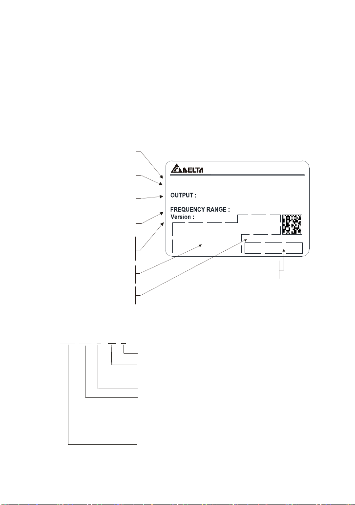
1.1.1 Nameplate Information
Example for 1HP/0.75kW 3-phase 230V AC motor drive
輸入端電壓/電流範圍;
輸入端電壓/電流範圍;
Input voltage/current
輸出端電壓/電流範圍;
輸出端電壓/電流範圍;
Output voltage/current
韌體版本:驅動板 控制板;/
韌體版本: ;驱动板 控 制板/
Drive board/Control board
機種名稱;
機種名稱 ;
Model name
頻率範圍;
頻率範圍;
Frequency range
Firmware version:
國際認證標示區;
國際認證標示區;
Certifications
序號;
序號 ;
ial numbe
DELTA EL EC TRO N ICS , INC.
MODE L: VFD0 07 E2 3 A
3PH 20 0-240V 50/60Hz 5.1A
INP UT :
3PH 0-240V 4.2A 1.6KVA
0.75kW/1H P
01.23 /02.2 3
0.1-59 9Hz
007E23A0T06220001
生產識別;
Product identification
生产识别 ;
1.1.2 Model Explanation
A: Standard driv
VFD
007
E
002: 0.25 HP(0.2kW)
004: 0.5 HP(0.4kW)
007: 1 HP(0.75kW)
015: 2 HP(1.5kW)
022: 3 HP(2.2kW)
23
A
Version Type
Mains Input Voltage
11:115 Single phaseV
23:230 Three phaseV
E Series
Applicable motor capacity
Series Name ( ariable requency rive)VF D
C: CANopen
P: Cold plate drive (frame A only)
T: Frame A, built-in brake chopper
21: phase230V Single
43:460 Th ree phaseV
185: 25 HP(18.5kW)
037: 5 HP(3.7kW)
055: 7.5 HP(5.5kW)
075: 10 HP(7 .5kW)
110: 15 HP(11kW)
150: 20 HP(15kW)
220: 30 HP(22kW)
1-2
Page 10
1.1.3 Series Number Explanation
If the nameplate information does not correspond to your purchase order or if there are
any problems, please contact your distributor.
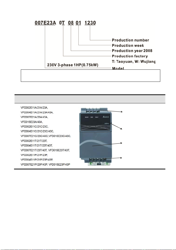
1.1.4 Drive Frames and Appearances
0.25-2HP/0.2-1.5kW (Frame A)
In p u t term inals
(R/L1, S/L2, T/L3)
Keypad cover
Control board cover
Output termi nals
(U/T1, V/T2, W/T3)
1-3
Page 11
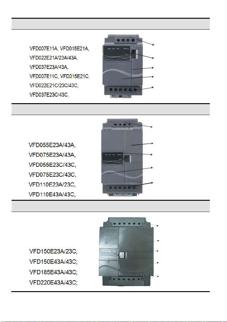
1-5HP/0.75-3.7kW (Frame B)
7.5-15HP/5.5-11kW (Frame C)
20-30HP/15-22kW (Frame D)
Input terminals
(R/L1, S/L2, T/L3)
Keypad cover
Case body
Cont rol board cover
Output terminals
(U/T1, V/T2, W/T3)
Input terminals
(R/L1, S/L2, T /L3)
Case body
Keypad cove r
Control board cover
Output terminals
(U/T1, V/T2, W/T3)
Input t er m i nal s
(R/L1, S/L2, T/L3)
Case body
Keyp ad cover
Control board cover
Output terminals
(U/T1, V/T2, W/T3)
1-4
Page 12
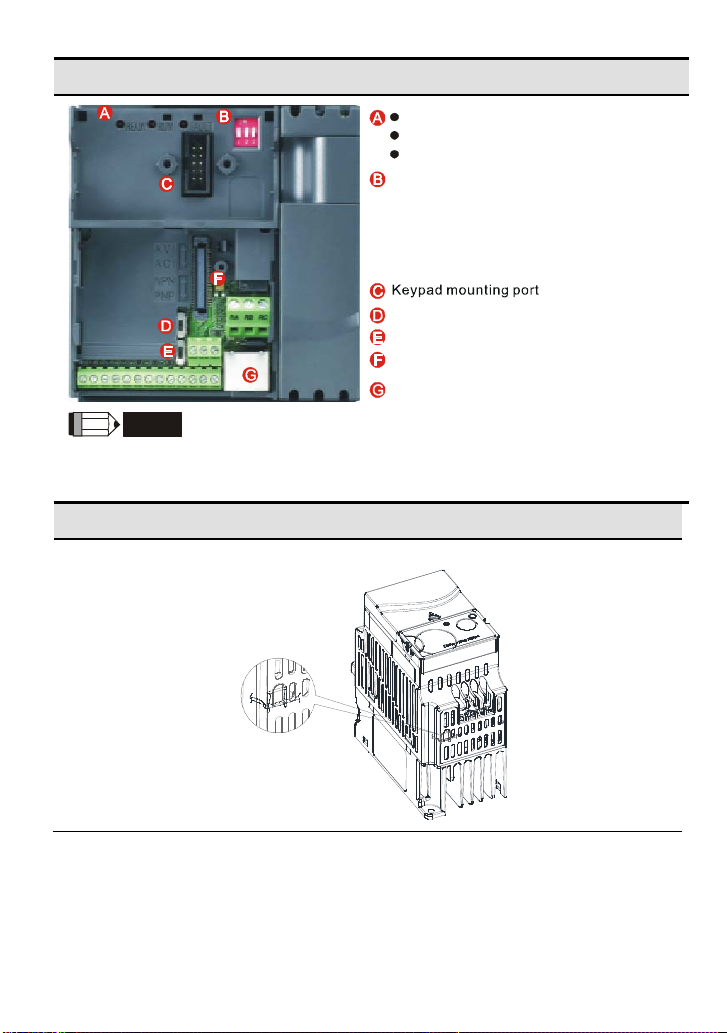
Internal Structure
/
READY
RUN
AVI2
ACI
NPN
PNP
FAULT
ON
1
2
3
READY: powerindicator
RUN: status indicator
FAULT: fault indicat o r
1.
Switchto ONfor 50Hz, referto
P01.00to P01.02for details
2.
Switch to ONfor freerun tostop
refer to P02.0 2
Switch to ONfor setting frequency
3.
sourceto ACI ( P 02.00=2)
ACI terminal (ACI
AVI2 switch )
NPN/PNP
Mounting p ort forextension card
NOTE
RS485 port (RJ-45)
The LED “READY” will light up after applying power. The light won’t be off until the capacitors are
discharged to safe voltage levels after power off.
RFI Jumper Location
Frame A: near the output terminals (U/T1, V/T2, W/T3)
1-5
Page 13
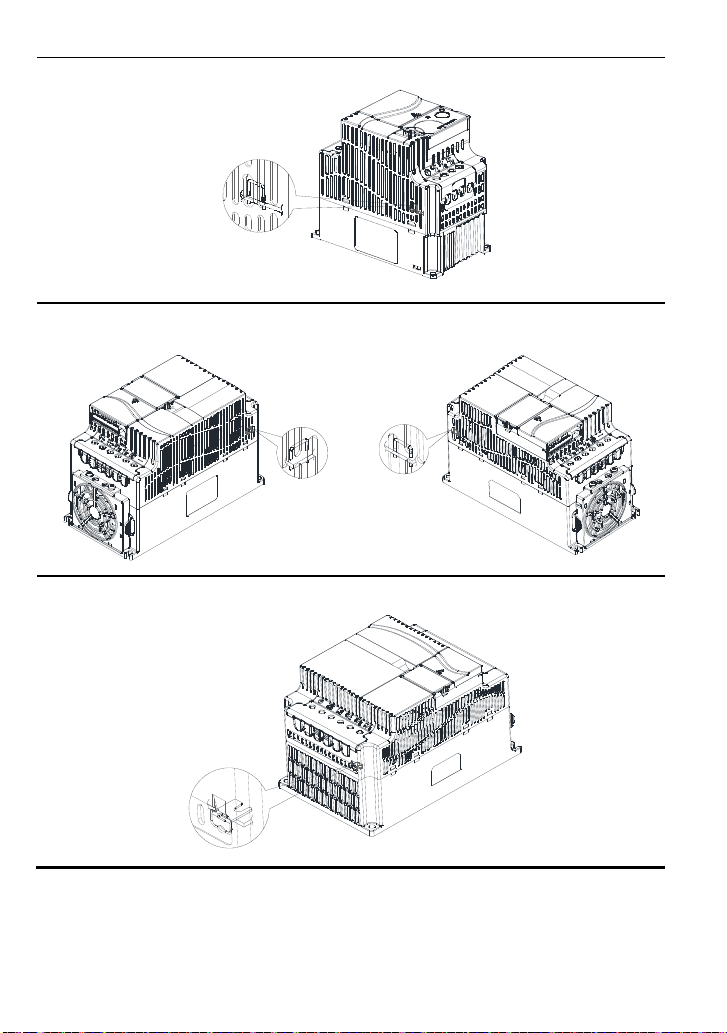
Frame B: above the nameplate
Frame C (230V): near the input terminals
(R/L1, S/L2, T/L3)
Frame C (460V): near the input terminals
(R/L1, S/L2, T/L3)
Frame D: near the input terminals (R/L1, S/L2, T/L3), under terminal R/L1.
Main power isolated from earth:
If the AC motor drive is supplied from an isolated power (IT power), the RFI jumper must be cut off.
Then the RFI capacities (filter capacitors) will be disconn ected from ground to prevent circuit damage
1-6
Page 14

(according to IEC 61800-3) and reduce earth leakage current.
CAUTION!
1. After applying power to the AC motor drive, do not cut off the RFI jumper. Therefore, make sure
that main power has been switched off before cutting the RFI jumper.
2. The gap discharge may occur when the transient voltage is higher than 1,000V. Besides, electromagnetic compatibility of the AC motor drives will be lower after cutting the RFI jumper.
3. Do NOT cut the RFI jumper when main power is connected to earth.
4. The RFI jumper cannot be cut when Hi-pot tests are performed. The mains power and motor must
be separated if high voltage test is performed and the leakage currents are
too high.
5. To prevent drive damage, the RFI jumper connected to ground shall be cut off if the AC motor drive
is installed on an ungrounded power system or a high resistance-grounded(over 30 ohms) power
system or a corner grounded TN system.
Frame Power range Models
A
0.25-2hp
(0.2-1.5kW)
VFD002E11A/11C/11T/11P; VFD002E21A/21C/21T/21P;
VFD002E23A/23C/23T/23P;
VFD004E11A/11C/11T/11P; VFD004E21A/21C/21T/21P;
VFD004E23A/23C/23T/23P; VFD004E43A/43C/43T/43P;
VFD007E21A/21C/21T/21P; VFD007E23A/23C/23T/23P;
VFD007E43A/43C/43T/43P;
VFD015E23A/23C/23T/23P; VFD015E43A/43C/43T/43P;
B
C
D
Note: Frame C VFD055E23A/23C; VFD075E23A/23C; VFD110E23A/23C; do not provide RFI functions.
1-5hp
(0.75-3.7kW)
7.5-15hp
(5.5-11kW)
20-30hp
(15-22kW)
VFD007E11A/11C; VFD015E21A/21C;
VFD022E21A/21C; VFD022E23A/23C; VFD022E43A/43C;
VFD037E23A/23C; VFD037E43A/43C;
VFD055E43A/43C; VFD075E43A/43C; VFD110E43A/43C;
VFD150E23A/23C; VFD150E43A43C;
VFD185E43A/43C; VFD220E43A/43C;
1-7
Page 15
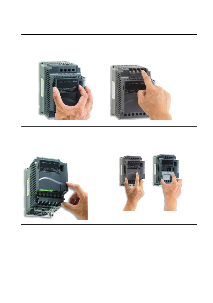
1.1.5 Remove Instructions
Remove Keypad
Press and hold in the latch on each side of
cover then pull the cover up to release.
Remove RST Terminal Cover
For Frame B, C and D: it only needs to turn the
cover lightly to open it.
For Frame A, it doesn’t have cover and can be
wired directly.
Remove UVW Terminal Cover
For Frame B, C and D: it only needs to turn the
cover lightly to open it.
For Frame A, it doesn’t have cover and can be
wired directly.
Remove Front Cover
Press the control board terminal cover first as
shown in Figure A, then slide downwards as
shown in Figure B, you can easily remove it.
1-8
Figure A Figure B
Page 16

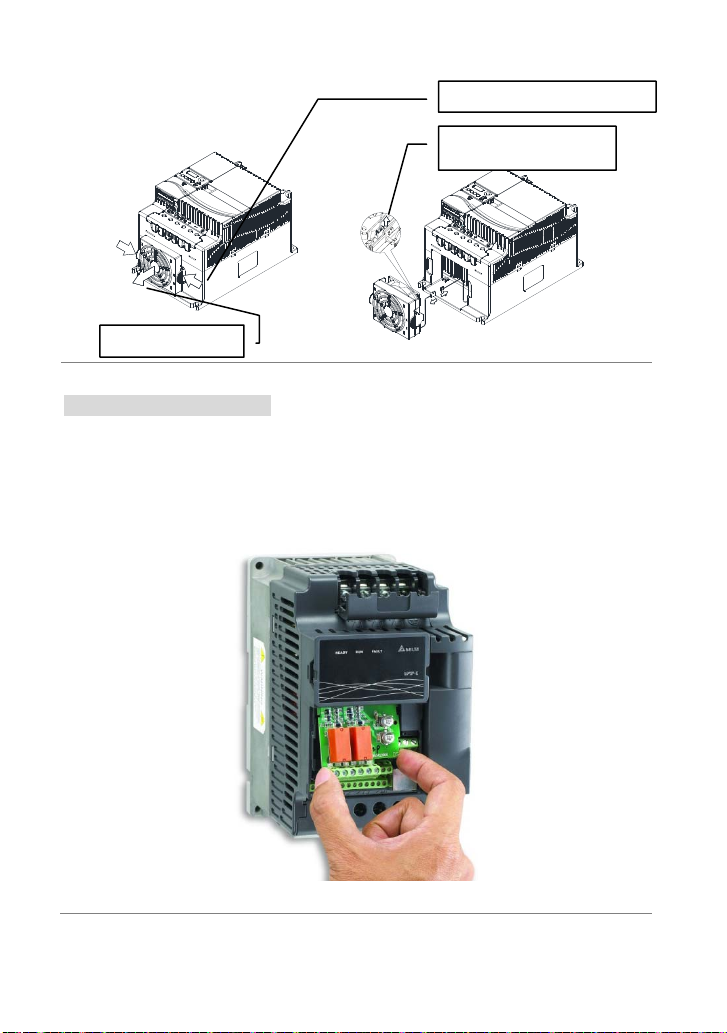
Remove Cooling Fan
Press and hold in the latch on each side of the fan and pull the fan up to release.
Frame A
3. Detach the power
cord from the fan.
2. Remove the fan.
Frame B
Frame C
3. Remove the fan.
3. Detach the power
cord from the fan.
2. Remove the fan.
1. Press the left
1. Loose the two screws
and right latches.
1. Press the left and
right latches.
1-9
4. Detach the power cord
from the fan.
2. Press the left and right latches.
Page 17
Frame D
1. Press the left and right latches.
3. Detach the power cord
from the fan.
2. Remove the fan.
Remove Extension Card
For Frame A, Frame B, Frame C and Frame D
Loosen the screws first then press and hold in the latche s on each side of the extension card
and pull the extension card up to release. On the other hand, it can install the extension card
into the AC motor drive with screws.
1-10
Page 18
1.2 Preparation for Installation and Wiring
1.2.1 Ambient Conditions
Install the AC motor drive in an environment with the following conditions:
Air Temperature:
Relative Humidity: <90%, no condensation allowed
Atmosphere
Operation
Storage
Transportation
Pollution
Degree
pressure:
Installation Site
Altitude:
Vibration:
Temperature: -20°C ~ +60°C (-4°F ~ 140°F)
Relative Humidity: <90%, no condensation allowed
Atmosphere
pressure:
Vibration: According to ISTA Procedure 1A
2: good for a factory type environment.
-10 ~ +50°C (14 ~ 122°F) for UL & cUL
-10 ~ +40°C (14 ~ 104°F) for side-by-side mounting
86 ~ 106 kPa
<1000m
10Hz≦f≦57Hz, Fix Amplitude: 0.075mm
57Hz≦f≦150Hz, fix Acceleration: 1G
(According to IEC 60068-2-6)
86 ~ 106 kPa
1-11
Page 19
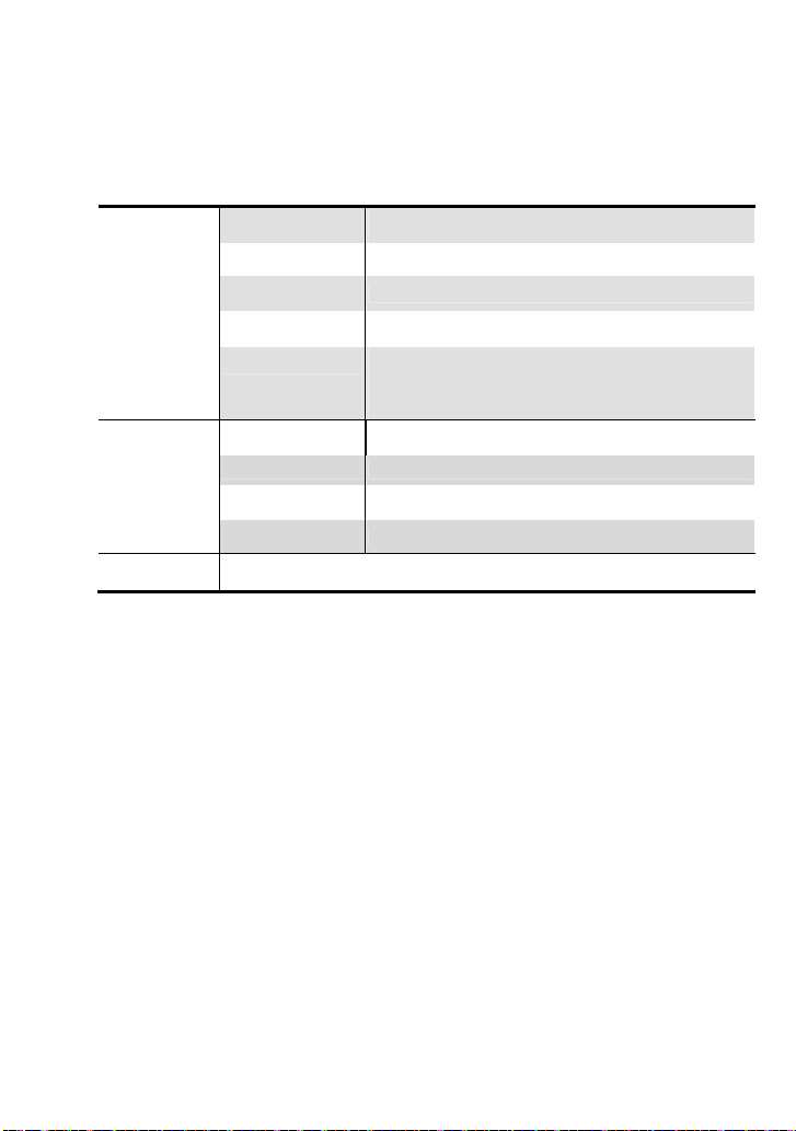
Minimum Mounting Clearances
Frame A Mounting Clearances
Single drive Side-by-side installation Air flow
120mm
m
m
0
m
m
0
5
5
120mm
Frame B, C and D Mounting Clearances
Single drive Side-by-side installation Air flow
150mm
m
m
0
m
m
0
5
5
150mm
120mm
m
m
0
5
150mm
m
m
0
5
120mm
150mm
m
m
0
5
Air Flow
Air Flow
m
m
0
5
1-12
Page 20
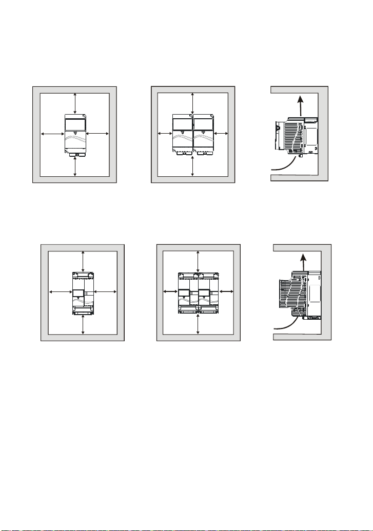
For VFD-E-P series: heat sink system example
C
Air-extracting apparatus
Control panel
AC motor drive
Duct temp era ture
Air flow speed
2m/sec
40
dust collector
's heat sink should comply
User
C
with following conditions:
1. Flatness <0.1mm
2. Roughness <6um
3. Grease 10um~12um
4. Screw torque: 16Kgf-cm
5. Recommended temperature <80
fan
CAUTION!
1. Operating, storing or transporting the AC motor drive outside these conditions may cause
damage to the AC motor drive.
2. Failure to observe these precautions may void the warranty!
3. Mount the AC motor drive vertically on a flat vertical surface object by screws. Other directions
are not allowed.
4. The AC motor drive will generate heat during operation. Allow sufficient space around the unit
for heat dissipation.
5. The heat sink temperature may rise to 90°C when running. The material on which the AC motor
drive is mounted must be noncombustible and be able to withstand this high temperature.
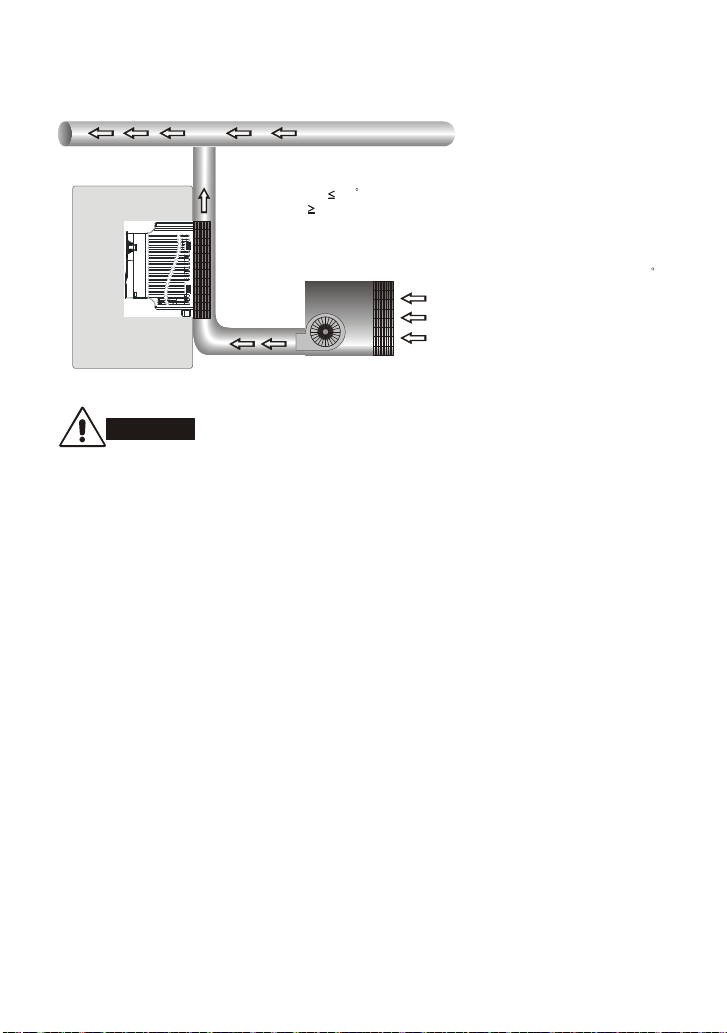
6. When AC motor drive is installed in a confined space (e.g. cabinet), the surrounding
temperature must be within 10 ~ 40°C with good ventilation. DO NOT install the AC motor drive
in a space with bad ventilation.
7. Prevent fiber particles, scraps of paper, saw dust, metal particles, etc. from adhering to the
heatsink.
8. When installing multiple AC more drives in the same cabinet, they should be adjacent in a row
with enough space in-between. When installing one AC motor drive below another one, use a
metal separation between the AC motor drives to prevent mutual heating.
1-13
Page 21
Installation with Metal Separation Installation without Metal Separation
120mm
120mm
120mm
120mm
F ram e A F ram e B, C and D
1φ/110V
Model Total Power Dissipation (W) Flow rate (CFM)
VFD002E11A/C/T 22 Natural Convection
VFD004E11A/C/T 33 Natural Convection
VFD007E11A 54 14
VFD002E11P 22 VFD004E11P 33 -
1φ/230V
Model Total Power Dissipation (W) Flow rate (CFM)
VFD002E21A/C/T 22 Natural Convection
VFD004E21A/C/T 34 Natural Convection
VFD007E21A/C/T 57 Natural Convection
VFD015E21A/C 97 14
VFD022E21A/C 142 14
VFD002E21P 22 VFD004E21P 34 VFD007E21P 57 -
3φ/230V
Model Total Power Dissipation (W) Flow rate (CFM)
VFD002E23 A/C/T 19 Natural Convection
VFD004E23 A/C/T 29 Natural Convection
VFD007E23 A/C/T 49 Natural Convection
VFD015E23 A/C/T 87 14
Air flow
150mm
150mm
150mm
150mm
1-14
120mm
A
120mm
Frame A
A
Frame B, C and D
150mm
B
B
150mm
Page 22

VFD022E23A/C 117 14
VFD037E23A/C 182 14
VFD055E23A/C 265 36
VFD075E23A/C 352 36
VFD110E23A/C 480 36
VFD150E23A/C 695 72
VFD002E23P 19 VFD004E23P 29 VFD007E23P 49 VFD015E23P 87 -
3φ/480V
Model Total Power Dissipation (W) Flow rate (CFM)
VFD004E43A/C/T 30 Natural Convection
VFD007E43A/C/T 51 Natural Convection
VFD015E43A/C/T 84 14
VFD022E43A/C 100 14
VFD037E43A/C 155 14
VFD055E43A/C 235 36
VFD075E43A/C 327 36
VFD110E43 A/C 436 36
VFD150E43 A/C 538 88
VFD185E43 A/C 570 88
VFD220E43 A/C 676 88
VFD004E43P 30 VFD007E43P 51 VFD015E43P 84 -
1-15
Page 23
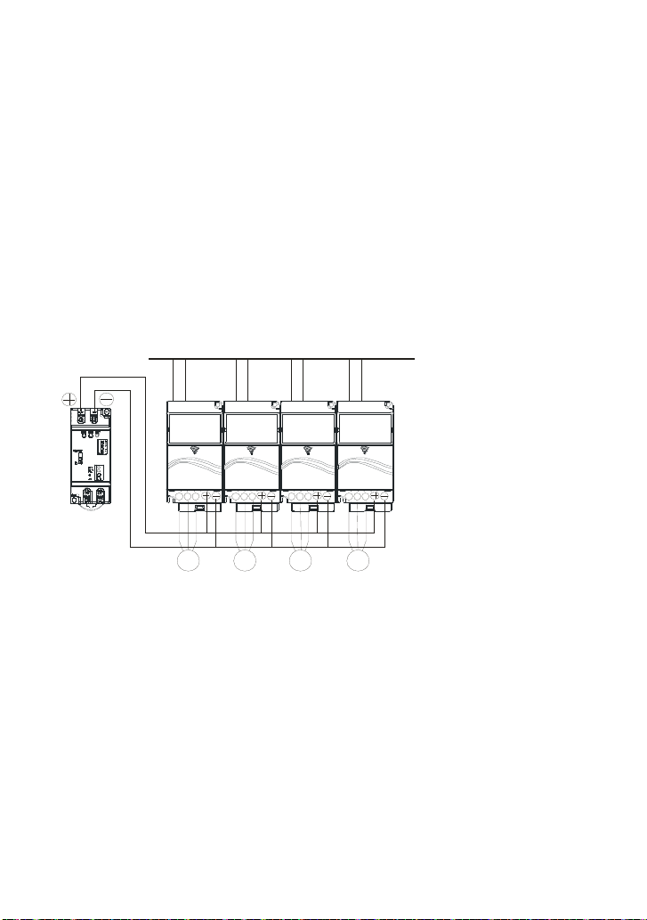
1.2.2 DC-bus Sharing: Connecting the DC-bus of the AC Motor Drives
in Parallel
1. This function is not for VFD-E-T series.
2. The AC motor drives can absorb mutual voltage that generated to DC bus when
deceleration.
3. Enhance brake function and stabilize the voltage of the DC bus.
4. The brake module can be added to enhance brake function after connecting in parallel.
5. Only the same power system and capacity can be connected in parallel.
6. It is recommended to connect 5 AC motor drives in parallel (no limit in horsepower but
these 5 drives should be the same power system and capacity).
power should be applied at the same time
(only the same power system and capacity can be connected in parallel)
Power 208/220/2 30/380/440/480 (depend on models)
U V W U V W U V W U V W
Brake
module
IM IM IM IM
For frame A, terminal + (-) is conn ected to the terminal + (-) of the br ake module.
For frame B, C and D, terminal +/B1 (-) is connected to th e terminal + (-) of the brake module.
1-16
Page 24
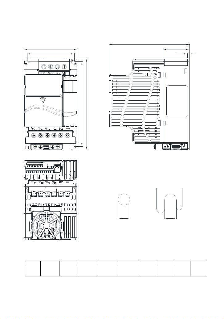
1.3 Dimensions
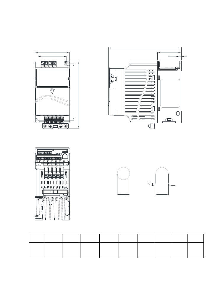
Frame A
VFD002E11A/11C/11T; VFD002E21A/21C/21T; VFD002E23A/23C/23T; VFD004E11A/11C/11T;
VFD004E21A/21C/21T; VFD004E23A/23C/23T; VFD004E43A/43C/43T; VFD007E21A/21C/21T;
VFD007E23A/23C/23T; VFD007E43A/43C/43T;
W
W1
H1
H
D
D1
D2
S2S1
Frame W W1 H H1 D D1 D2 S1 S2
A1
72.0
[2.83]
60.0
[2.36]
142.0
[5.59]
120.0
[4.72]
1-17
152.0
[5.98]
50.0
[1.97]
4.5
[0.18]
Unit: mm [inch]
5.2
5.2
[0.20]
[0.20]
Page 25
Frame A
VFD015E23A/23C/23T; VFD015E43A/43C/43T;
W
W1
H1
H
D
D1
D2
S2S1
Frame W W1 H H1 D D1 D2 S1 S2
A2
72.0
[2.83]
60.0
[2.36]
142.0
[5.59]
120.0
[4.72]
1-18
152.0
[5.98]
50.0
[1.97]
4.5
[0.18]
[0.20]
Unit: mm [inch]
5.2
5.2
[0.20]
Page 26
Frame A
VFD002E11P/21P/23P; VFD004E11P/21P/23P/43P; VFD007E21P/23P/43P; VFD015E23P/43P;
W
W1
H1
H
D
D1
S1
Unit: mm [inch]
Frame W W1 H H1 D D1 S1
A3
72.0
[2.83]
56.0
[2.20]
155.0
[6.10]
1-19
143.0
[5.63]
111.5
[4.39]
9.5
[0.37]
5.3
[0.21]
Page 27
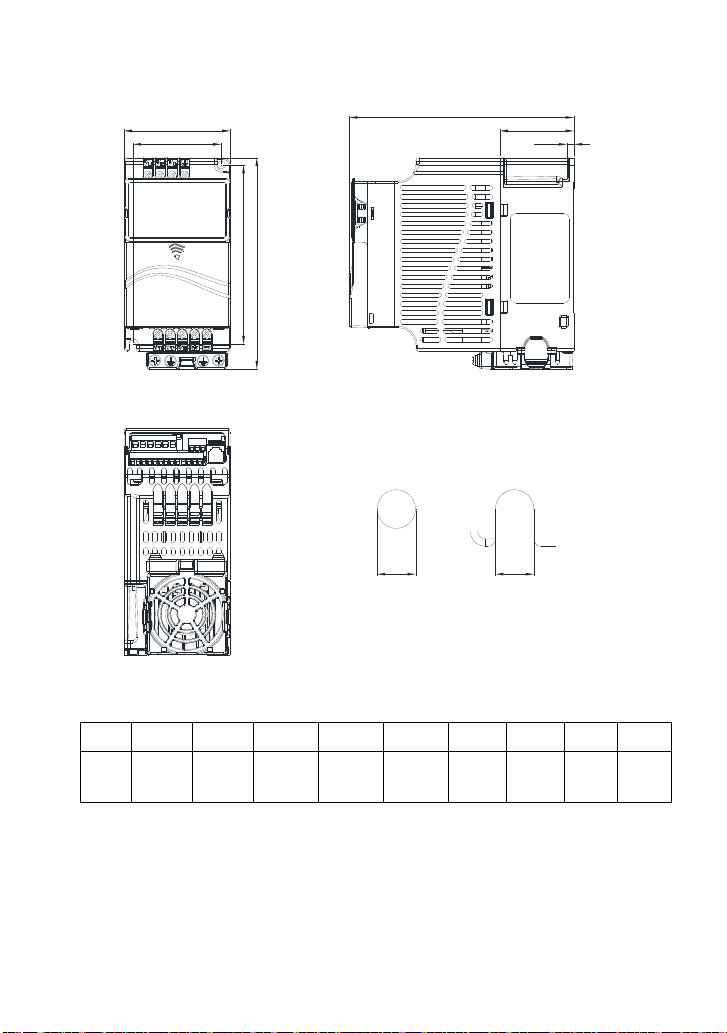
Frame B
VFD007E11A/11C; VFD015E21A/21C; VFD022E21A/21C; VFD022E23A/23C; VFD022E43A/43C;
VFD037E23A/23C; VFD037E43A/43C;
W
W1
H1
H
D
D1
D2
4.0
[0.16]
S2
[0.22]
S1
Frame W W1 H H1 D D1 D2 S1 S2
100.0
B
[3.94]
89.0
[3.50]
174.0
[6.86]
162.0
[6.38]
1-20
152.0
[5.98]
50.0
[1.97]
Unit: mm [inch]
5.5
5.5
[0.22]
Page 28

Frame C
VFD055E23A/23C; VFD055E43A/43C; VFD075E23A/23C; VFD075E43A/43C; VFD110E23A/23C;
VFD110E43A/43C;
D
W1
W
H
H1
D1
D2
S1
S2
Frame W W1 H H1 D D1 D2 S1 S2
130.0
[5.12]
116.0
[4.57]
C
260.0
[10.24]
246.5
[9.70]
1-21
169.2
[6.66]
78.5
[3.09]
8.0
[0.31]
Unit: mm [inch]
6.5
[0.26]
5.5
[0.22]
Page 29
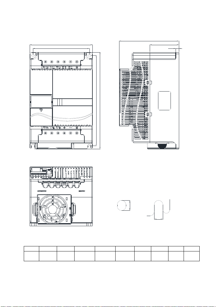
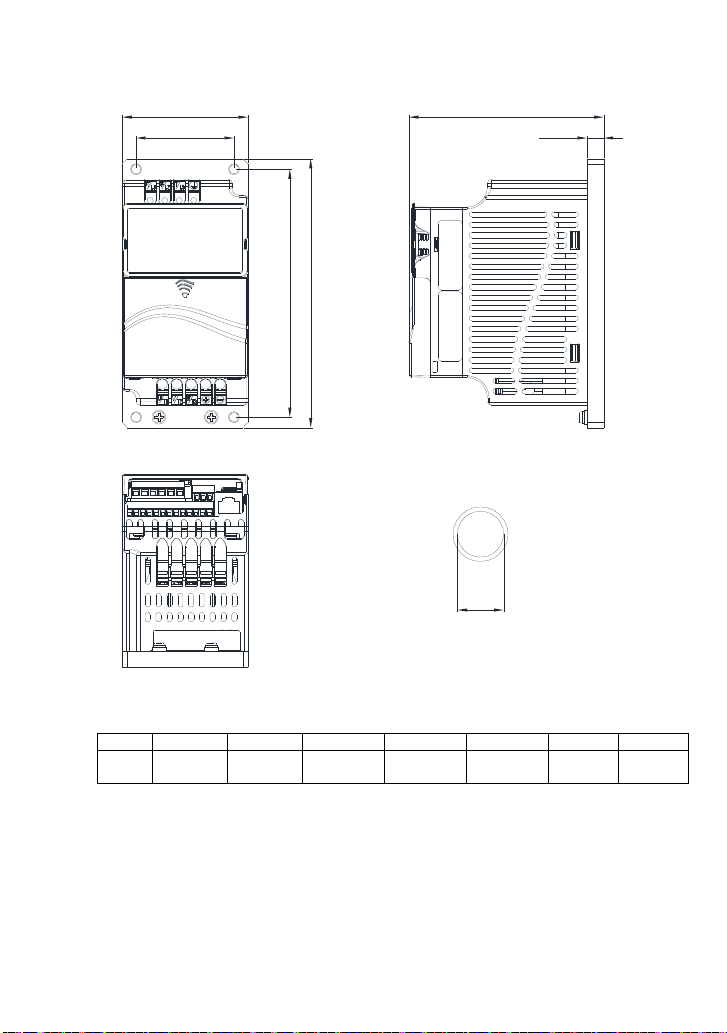
Frame D
VFD150E23A/23C; VFD150E43A43C; VFD185E43A/43C; VFD220E43A/43C;
W
W1
H
H1
S1
D
D1
D2
S2
Frame W W1 H H1 D D1 D2 S1 S2
200.0
[7.87]
180.0
[7.09]
D
310.0
[12.20]
290.0
[11.42]
190.0
[7.48]
92.0
[3.62]
10.0
[0.39]
[0.39]
1-22
Unit: mm [inch]
10.0
9.0
[0.35]
Page 30

Chapter 2 Installation & Wiring
Chapter 2 Installation & Wiring
After removing the front cover, check if the power and control terminals are clear. Be sure to observe
the following precautions when wiring.
General Wiring Information
Applicable Codes
All VFD-E series are Underwriters Laboratories, Inc. (UL) and Canadian Underwriters
Laboratories (cUL) listed, and therefore comply with the requirements of the National
Electrical Code (NEC) and the Canadian Electrical Code (CEC).
Installation intended to meet the UL and cUL requirements must follow the instructions
provided in “Wiring Notes” as a minimum standard. Follow all local codes that exceed UL
and cUL requirements. Refer to the technical data label affixed to the AC motor drive and
the motor nameplate for electrical data.
The "Line Fuse Specification" in Appendix B, lists the recommended fuse part number for
each VFD-E Series part number. These fuses (or equivalent) must be used on all
installations where compliance with U.L. standards is a required.
CAUTION!
1. Make sure that power is only applied to the R/L1, S/L2, T/L3 terminals. Failure to comply may
result in damage to the equipment. The voltage and current should lie within the range as
indicated on the nameplate.
2. All the units must be grounded directly to a common ground terminal to prevent lightning strike
or electric shock.
3. Please make sure to fasten the screw of the main circuit terminals to prevent sparks which is
made by the loose screws due to vibration.
4. Check following items after finishing the wiring:
A. Are all connections correct?
B. No loose wires?
C. No short-circuits between terminals or to ground?
2-1
Page 31

Chapter 2 Installation & Wiring
DANGER!
1. A charge may still remain in the DC bus capacitors with hazardous voltages even if the power
has been turned off. To prevent personal injury, please ensure that the power is turned off and
wait ten minutes for the capacitors to discharge to safe voltage levels before opening the AC
motor drive.
2. Only qualified personnel familiar with AC motor drives is allowed to perform installation, wiring
and commissioning.
3. Make sure that the power is off before doing any wiring to prevent electric shock.
2-2
Page 32

Chapter 2 Installation & Wiring
2.1 Wiring
Users must connect wires according to the circuit diagrams on the following pages. Do not plug a
modem or telephone line to the RS-485 communication port or permanent damage may result. The
pins 1 & 2 are the power supply for the optional copy keypad only and should not be used for RS-485
communication.
Figure 1 for models of VFD-E Series
VFD002E11A/21A, VFD004E11A/21A, VFD007E21A, VFD002E11C/21C, VFD004E11C/21C,
VFD007E21C, VFD002E11P/21P, VFD004E11P/21P, VFD007E21P
2
2-3
Page 33

Figure 2 for models of VFD-E Series
VFD002E23A, VFD004E23A/43A, VFD007E23A/43A, VFD015E23A/43A, VFD002E23C,
VFD004E23C/43C, VFD007E23C/43C, VFD015E23C/43C, VFD002E23P, VFD004E23P/43P,
VFD007E23P/43P, VFD015E23P/43P
Chapter 2 Installation & Wiring
2
2-4
Page 34

Figure 3 for models of VFD-E Series
VFD007E11A, VFD015E21A, VFD022E21A, VFD007E11C, VFD015E21C, VFD022E21C
Chapter 2 Installation & Wiring
2
2-5
Page 35

Figure 4 for models of VFD-E Series
VFD022E23A/43A, VFD037E23A/43A, VFD055E23A/43A, VFD075E23A/43A, VFD110E23A/43A,
VFD022E23C/43C, VFD037E23C/43C, VFD055E23C/43C, VFD075E23C/43C, VFD110E23C/43C,
VFD150E23A/23C, VFD150E43A/43C, VFD185E43A/43C, VFD220E43A/43C
Chapter 2 Installation & Wiring
2
2-6
Page 36

Figure 5 for models of VFD-E Series
VFD002E11T/21T, VFD004E11A/21T, VFD007E21T
2
Chapter 2 Installation & Wiring
2-7
Page 37

Figure 6 for models of VFD-E Series
VFD002E23T, VFD004E23T/43T, VFD007E23T/43T, VFD015E23T/43T
Chapter 2 Installation & Wiring
2
2-8
Page 38

Figure 7 Wiring for NPN mode and PNP mode
A. NPN mode without external power
NPN
PNP
Factory
setting
Chapter 2 Installation & Wiring
B. NPN mode with external power
C. PNP mode without external power
NPN
PNP
Factory
setting
NPN
Sw1
PNP
Factory
setting
-
24
Vdc
+
2-9
Page 39

D. PNP mode with external power
NPN
Sw1
PNP
Factory
setting
+
24
Vdc
-
Chapter 2 Installation & Wiring
Figure 8 Pin definition for VFD*E*C CANopen models
(Note: CANopen models can’t use PU06)
PIN Signal Description
1 CAN_H CAN_H bus line (dominant high)
2 CAN_L CAN_L bus line (dominant low)
3 CAN_GND Ground / 0V /V-
4 SG- 485 communication
5 SG+ 485 communication
6 GND Ground
7 CAN_GND Ground / 0V /V-
8 EV Power
CAUTION!
1. The wiring of main circuit and control circuit should be separated to prevent erroneous actions.
2. Please use shield wire for the control wiring and not to expose the peeled-off net in front of the
terminal.
3. Please use the shield wire or tube for the power wiring and ground the two ends of the shield
wire or tube.
4. Damaged insulation of wiring may cause personal injury or damage to circuits/equipment if it
comes in contact with high voltage.
5. The AC motor drive, motor and wiring may cause interference. To prevent the equipment
2-10
Page 40

Chapter 2 Installation & Wiring
damage, please take care of the erroneous actions of the surrounding sensors and the
equipment.
6. When the AC drive output terminals U/T1, V/T2, and W/T3 are connected to the motor terminals
U/T1, V/T2, and W/T3, respectively. To permanently reverse the direction of motor rotation,
switch over any of the two motor leads.
7. With long motor cables, high capacitive switching current peaks can cause over-current, high
leakage current or lower current readout accuracy. To prevent this, the motor cable should be
less than 20m for 3.7kW models and below. And the cable should be less than 50m for 5.5kW
models and above. For longer motor cables use an AC output reactor.
8. The AC motor drive, electric welding machine and the greater horsepower motor should be
grounded separately.
9. Use ground leads that comply with local regulations and keep them as short as possible.
10. No brake resistor is built in the VFD-E series, it can install brake resistor for those occasions
that use higher load inertia or frequent start/stop. Refer to Appendix B for details.
2-11
Page 41

Chapter 2 Installation & Wiring
11. Multiple VFD-E units can be installed in one location. All the units should be grounded directly
to a common ground terminal, as shown in the figure below. Ensure there are no ground
loops.
Excellent
Good
Not allowed
2-12
Page 42

2.2 External Wiring
y
Chapter 2 Installation & Wiring
Power Suppl
EMI Filter
R/L1 S/L2
U/T1 V/T2
T/L3
W/T3
FUSE/NFB
Magnetic
contactor
Input AC
Line Reactor
Zero-phase
Reactor
Brake
+/B1
B2
-
Zero-phase
Reactor
Output AC
Line Reactor
Items Explanations
Power
supply
Please follow the specific power
supply requirements shown in
Appendix A.
There may be an inrush current
Fuse/NFB
(Optional)
during power up. Please check the
chart of Appendix B and select the
correct fuse with rated current. Use of
an NFB is optional.
Magnetic
contactor
(Optional)
Please do not use a Magnetic
contactor as the I/O switch of the AC
motor drive, as it will reduce the
operating life cycle of the AC drive.
Used to improve the input power
factor, to reduce harmonics and
provide protection from AC line
disturbances. (surges, switching
Input AC
Line Reactor
(Optional)
spikes, short interruptions, etc.). AC
line reactor should be installed when
the power supply capacity is 500kVA
or more or advanced capacity is
activated .The wiring distance should
be
10m. Refer to appendix B for
details.
Zero phase reactors are used to
Zero-phase
Brake unit
BR
BUE
Reactor
(Ferrite Core
Common
Choke)
resistor
(Optional)
reduce radio noise especially when
audio equipment is installed near the
inverter. Effective for noise reduction
on both the input and output sides.
Attenuation quality is good for a wide
range from AM band to 10MHz.
Appendix B specifies the zero phase
reactor. (RF220X00A)
EMI filter
Brake
resistor and
Brake unit
(Optional)
To reduce electromagnetic
interference.
Used to reduce the deceleration time
of the motor. Please refer to the chart
in Appendix B for specific Brake
resistors.
Motor
Output AC
Line Reactor
(Optional)
2-13
Motor surge voltage amplitude
depends on motor cable length. For
applications with long motor cable
(>20m), it is necessary to install a
Page 43

Chapter 2 Installation & Wiring
)
2.3 Main Circuit
2.3.1 Main Circuit Connection
Figure 1
For frame A: VFD002E11A/21A/23A, VFD004E11A/21A/23A/43A, VFD007E21A/23A/43A,
VFD002E11C/21C/23C, VFD004E11C/21C/23C/43C, VFD007E21C/23C/43C,
VFD002E11P/21P/23P, VFD004E11P/21P/23P/43P, VFD007E21P,
VFD015E23A/43A /23P /43P
No fuse breaker
(NF B)
R
S
T
MC
Figure 2
For frame B: VFD007E11A, VFD015E21A, VFD022E21A/23A/43A, VFD037E23A/43A,
VFD007E11C, VFD015E21C, VFD022E21C/23C/43C, VFD037E23C/43C
For frame C: VFD055E23A/43A, VFD075E23A/43A, VFD110E23A/43A, VFD055E23C/43C,
VFD075E23C/43C, VFD110E23C/43C
For frame D: VFD150E23A/23C, VFD150E43A/43C, VFD185E43A/43C, VFD220E43A/43C
No fuse breaker
( NFB)
R
MC
S
T
Figure 3
For Frame A: VFD002E11T/21T/23T, VFD004E11T/21T/23T/43T, VFD007E21T/23T/43T,
VFD015E23T/43T
No fuse breaker
(NFB)
R
MC
S
T
Brake Resist or(Optional)
BR
BUE
+
R(L1)
S(L2)
T(L3)
E
Brake Resistor(Optional
BR
B2
+/B1
R(L1)
S(L2)
T(L3)
E
BR
B1 B2
R(L1)
S(L2)
T(L3)
E
Brake Unit
(Optional)
-
U(T1)
V(T2)
W(T3)
E
U(T1)
V(T2)
W(T3)
Brake Resistor
(Optional)
U(T1)
V(T2)
W(T3)
Motor
E
E
IM
3~
Motor
Motor
IM
3~
IM
3~
2-14
Page 44

Chapter 2 Installation & Wiring
Terminal Symbol Explanation of Terminal Function
R/L1, S/L2, T/L3
U/T1, V/T2, W/T3
+/B1~ B2
+/B1, -
AC line input terminals (1-phase/3-phase)
AC drive output terminals for connecting 3-phase induction motor
Connections for Brake resistor (optional)
Connections for External Brake unit (BUE series)
Earth connection, please comply with local regulations.
CAUTION!
Mains power terminals (R/L1, S/L2, T/L3)
Connect these terminals (R/L1, S/L2, T/L3) via a no-fuse breaker or earth leakage
breaker to 3-phase AC power (some models to 1-phase AC power) for circuit protection.
It is unnecessary to consider phase-sequence.
It is recommended to add a magnetic contactor (MC) in the power input wiring to cut off
power quickly and reduce malfunction when activating the protection function of AC motor
drives. Both ends of the MC should have an R-C surge absorber.
Please make sure to fasten the screw of the main circuit terminals to prevent sparks
which is made by the loose screws due to vibration.
Please use voltage and current within the regulation shown in Appendix A.
When using a general GFCI (Ground Fault Circuit Interrupter), select a current sensor
with sensitivity of 200mA or above, and not less than 0.1-second operation time to avoid
nuisance tripping. For the specific GFCI of the AC motor drive, select a current sensor
with sensitivity of 30mA or above.
Do NOT run/stop AC motor drives by turning the power ON/OFF. Run/stop AC motor
drives by RUN/STOP command via control terminals or keypad. If you still need to
run/stop AC drives by turning power ON/OFF, it is recommended to do so only ONCE per
hour.
Do NOT connect 3-phase models to a 1-phase power source.
2-15
Page 45

Chapter 2 Installation & Wiring
Output terminals for main circuit (U, V, W)
The factory setting of the operation direction is forward running. The methods to control
the operation direction are: method 1, set by the communication parameters. Please refer
to the group 9 for details. Method2, control by the optional keypad KPE-LE02. Refer to
Appendix B for details.
When it needs to install the filter at the output side of terminals U/T1, V/T2, W/T3 on the
AC motor drive. Please use inductance filter. Do not use phase-compensation capacitors
or L-C (Inductance-Capacitance) or R-C (Resistance-Capacitance), unless approved by
Delta.
DO NOT connect phase-compensation capacitors or surge absorbers at the output
terminals of AC motor drives.
Use well-insulated motor, suitable for inverter operation.
Terminals [+/B1, B2] for connecting brake resistor
BR
BR
BUE
BR
Brake resistor (optional)
Brake unit (optional)
Refer to Appendix B for details.
+/B1
Connect a brake resistor or brake unit in applications with frequent deceleration ramps,
B1
B2
+/B1
B2
-
short deceleration time, too low brake torque or requiring increased brake torque.
If the AC motor drive has a built-in brake chopper (frame B, frame C and VFDxxxExxT
models), connect the external brake resistor to the terminals [+/B1, B2] or [B1, B2].
Models of frame A don’t have a built-in brake chopper. Please connect an external
optional brake unit (BUE-series) and brake resistor. Refer to BUE series user manual for
details.
Connect the terminals [+(P), -(N)] of the brake unit to the AC motor drive terminals [+/B1, -
]. The length of wiring should be less than 5m with cable.
When not used, please leave the terminals [+/B1, -] open.
WARNING!
Short-circuiting [B2] or [-] to [+/B1] can damage the AC motor drive.
2-16
Page 46

2.3.2 Main Circuit Terminals
Frame A
Frame B
Main circuit terminals:
R/L1, S/L2, T/L3, U/T1, V/T2, W/T3,
Recommend round terminal spec(UL recognized)
Chapter 2 Installation & Wiring
, +, -
Models Wire Torque
VFD002E11A/11C/11T/11P;
VFD002E21A/21C/21T/21P;
VFD002E23A/23C/23T/23P;
VFD004E11A/11C/11T/11P;
VFD004E21A/21C/21T/21P;
VFD004E23A/23C/23T/23P;
VFD004E43A/43C/43T/43P;
VFD007E21A/21C/21T/21P;
VFD007E23A/23C/23T/23P;
VFD007E43A/43C/43T/43P;
VFD015E23A/23C/23T/23P;
VFD015E43A/43C/43T/43P;
6.8 Max.
3.2 Min.
FOR M3 SCREW
6.4 Max.
WITH OR W/O INSULATOR(H EATSHRINK TUBE) AFTER
Main circuit terminals:
CRIMPING
R/L1, S/L2, T/L3, U/T1, V/T2, W/T3,
Mode s Wire (Min.)
VFD007E11A/11
C
VFD015E21A/21
C
VFD022E21A/21
C
VFD022E23A/23
C
VFD022E43A/43
C
VFD037E23A/23
C
VFD037E43A/43C 14 AWG.
10 AWG (5.3mm2)
12 AWG (3.3mm2)
10 AWG (5.3mm2)
12 AWG (3.3mm2)
14 AWG.
(2.1mm2)
10 AWG (5.3mm2)
(2.1mm2)
14 AWG.
(2.1mm2)
5.2 Min.
8 kgf-cm
(6.9 in-lbf)
, +/B1, B2, -
Wire
(Max.)
10 AWG
(5.3mm2)
Torque
18kgf-cm
(15.6in-lbf)
Recommend round terminal spec (UL recognized).
Wire
Type
Stranded
copper
only
600V,
75℃
or above
Wire
Type
Stranded
copper
only
600V ,
75℃
or above
2-17
Page 47

Frame C
Frame D
Main circuit terminals:
R/L1, S/L2, T/L3, U/T1, V/T2, W/T3,
Chapter 2 Installation & Wiring
, +/B1, B2, -
Models Wire (Min.)
VFD055E23A/23C 8 AWG (8.4mm2)
VFD075E23A/23C 8 AWG (8.4mm2)
VFD110E23A/23C 6 AWG (13.3mm2)
VFD055E43A/43C 12 AWG (3.3mm2)
VFD075E43A/43C 10 AWG (5.3mm2)
VFD110E43A/43C 8 AWG (8.4mm2)
Recommend round terminal spec (UL recognized)
5.2 Min.
FOR M5 SCREW
12.1 Max.
Wire
(Max.)
6 AWG
(13.3mm2)
30kgf-cm
(26in-lbf)
Torque
Wire
Type
Stranded
copper only
11.0 Min.
13.7 Max.
WITH OR W/O INSULA TOR(HEATSHRINK TUBE) AFTER
CRIMPING
Main circuit terminals:
R/L1, S/L2, T/L3, U/T1, V/T2, W/T3,
, B1, B2, +, -
Models Wire (Min.)
VFD150E23A/23C 4 AWG (21.2mm2)
VFD150E43A43C 8 AWG (8.4mm2)
VFD185E43A/43C 6 AWG (13.3mm2)
VFD220E43A/43C 6 AWG (13.3mm2)
* VFD150E23A/23C need to select wire can withstand voltage 600V
and temperature 90℃ above.
Wire
(Max.)
4 AWG
(21.2mm2)
Torque
57kgf-cm
(49.5in-lbf)
Wire
Type
Stranded
copper only
Recommend round terminal spec (UL recognized)
6.2 Min.
FOR M6 SCREW
17.5 Max.
600V ,
75℃ or
above
600V ,
75℃ or
above
2-18
16.7 Max.
WITH OR W/O INSULATOR(HEATSHRINK TUBE) AFTER
CRIMPING
13.5 Min.
Page 48

e
2.4 Control Terminals
Chapter 2 Installation & Wiring
Circuit diagram for digital inputs (NPN current 16mA.)
NPN Mode
multi-input
terminal
+24
Internal CircuitDCM
PNP Mod
Multi-Input
Termi nal
The position of the control terminals
DCM
DCM ACM
Terminal symbols and functions
Terminal
Symbol
MI1 Forward-Stop command
MI2 Reverse-Stop command
Terminal Function
ON: Run in MI1 direction
OFF: Stop acc. to Stop Method
ON: Run in MI2 direction
OFF: Stop acc. to Stop Method
MI3 Multi-function Input 3
MI4 Multi-function Input 4
MI5 Multi-function Input 5
Refer to Pr.04.05 to Pr.04.08 for programming the
Multi-function Inputs.
ON: the activation current is 6mA.
OFF: leakage current tolerance is 10μA.
MI6 Multi-function Input 6
DCM
+24V
Internal Circuit
RA
AFM MC M MO1
10VMI1 MI2 MI3 MI4 MI5 MI6
24V
AVI AC I
Factory Settings (NPN mode)
ON: Connect to DCM
RB RC
RS-485
+24V DC Voltage Source +24VDC, 120mA used for PNP mode.
2-19
Page 49

Terminal
Symbol
Terminal Function
DCM Digital Signal Common
Multi-function Relay output
RA
(N.O.) a
Multi-function Relay output
RB
(N.C.) b
RC Multi-function Relay common
Multi-function Output 1
MO1
(Photocoupler)
Chapter 2 Installation & Wiring
Factory Settings (NPN mode)
ON: Connect to DCM
Common for digital inputs and used for NPN
mode.
Resistive Load:
5A(N.O.)/3A(N.C.) 240VAC
5A(N.O.)/3A(N.C.) 24VDC
Inductive Load:
1.5A(N.O.)/0.5A(N.C.) 240VAC
1.5A(N.O.)/0.5A(N.C.) 24VDC
Refer to Pr.03.00 for programming
Maximum 48VDC, 50mA
Refer to Pr.03.01 for programming
Mo1
Max: 48Vdc
50mA
MO1-DCM
internal circuit
MCM
MCM Multi-function output common Common for Multi-function Outputs
+10V Potentiometer power supply +10VDC 3mA
Analog voltage Input
+10V
AVI cir cuit
Impedance: 47kΩ
Resolution: 10 bits
Range: 0 ~ 10VDC =
AVI
Analog control signal
ACM
(common)
AVI
ACM
internal circuit
0 ~ Max. Output Frequency
(Pr.01.00)
Selection: Pr.02.00, Pr.02.09, Pr.10.00
Set-up: Pr.04.11 ~ Pr.04.14, 04.19~04.23
Common for AVI2, ACI, AFM
Impedance: 250Ω/100kΩ
Resolution: 10 bits
ACI Analog current Input
Range: 4 ~ 20mA =
0 ~ Max. Output Frequency
(Pr.01.00)
Selection: Pr.02.00, Pr.02.09, Pr.10.00
2-20
Page 50

Chapter 2 Installation & Wiring
A
A
A
Terminal
Symbol
AFM
Terminal Function
ACI circuit
ACI
ACM
internal circuit
Analog output meter
ACM circuit
internal circuit
FM
CM
0~10V
potentiometer
Max. 2mA
Set-up: Pr.04.15 ~ Pr.04.18
0 to 10V, 2mA
Impedance: 100kΩ
Output current 2 mA m ax
Resolution: 8 bits
Range: 0 ~ 10VDC
Function: Pr.03.03 to Pr.03.04
Factory Settings (NPN mode)
ON: Connect to DCM
NOTE: Control signal wiring size: 18 AWG (0.75 mm2) with shielded wire.
Analog inputs (AVI, ACI, ACM)
Analog input signals are easily affected by external noise. Use shielded wiring and keep it
as short as possible (<20m) with proper grounding. If the noise is inductive, connecting
the shield to terminal ACM can bring improvement.
If the analog input signals are affected by noise from the AC motor drive, please connect
a capacitor (0.1F and above) and ferrite core as indicated in the following diagrams:
C
ferrite core
VI/ACI
ACM
wind each wires 3 times or more around the core
Digital inputs (MI1~MI6, DCM)
When using contacts or switches to control the digital inputs, please use high quality
components to avoid contact bounce.
Digital outputs (MO1, MCM)
Make sure to connect the digital outputs to the right polarity, see wiring diagrams.
When connecting a relay to the digital outputs, connect a surge absorber or fly-back diode
across the coil and check the polarity.
2-21
Page 51

General
A
Keep control wiring as far away as possible from the power wiring and in separate
conduits to avoid interference. If necessary let them cross only at 90º angle.
The AC motor drive control wiring should be properly installed and not touch any live
power wiring or terminals.
Chapter 2 Installation & Wiring
DANGER!
Damaged insulation of wiring may cause personal injury or damage to circuits/equipment if it comes
in contact with high voltage.
The specification for the control terminals
RA
RB RC
The position of the control terminals
Terminals 1
AFM MCM MO1
Terminals 2
RS-485 port
24V
CM
10VMI1 MI2MI3 MI4 MI5 MI6
AVI A CI
2
)
DCM
Frame Control Terminals Torque Wire
A, B, C, D
NOTE
Frame A:VFD002E11A/11C/11T/11P; VFD002E21A/21C/21T/21P;
Frame B:VFD007E11A/11C, VFD015E21A/21C, VFD022E21A/21C, VFD022E23A/23C,
Frame C:VFD055E23A/23C, VFD055E43A/43C, VFD075E23A/23C, VFD075E43A/43C,
Frame D:VFD150E23A/23C, VFD150E43A/43C, VFD185E43A/43C, VFD220E43A/
Terminals 1 5 kgf-cm (4.4 in-lbf) 12-24 AWG (3.3-0.2mm
Terminals 2 2 kgf-cm (1.7 in-lbf) 16-24 AWG (1.3-0.2mm2)
VFD002E23A/23C/23T/23P;VFD004E11A/11C/11T/11P;
VFD004E21A/21C/21T/21P; VFD004E23A/23C/23T/23P;
VFD004E43A/43C/43T/43P; VFD007E21A/21C/21T/21P;
VFD007E23A/23C/23T/23P; VFD007E43A/43C/43T/43P
VFD015E23A/23C/23T/23P; VFD015E43A/43C/43T/43P;
VFD022E43A/43C, VFD037E23A/23C, VFD037E43A/43C,
VFD110E23A/23C, VFD110E43A/43C,
DCM
2-22
Page 52

3.1 Keypad
Chapter 3 Keypad and Start Up
Chapter 3 Keypad and Start Up
Make sure that the wiring is correct. In particular, check that the
output terminals U/T1, V/T2, W/T3. are NOT connected to power
and that the drive is well grounded.
Verify that no other equipment is connected to the AC motor drive
Do NOT operate the AC motor drive with humid hands.
Please check if READY LED is ON when power is applied. Check
if the connection is well when option from the digital keypad KPELE02.
It should be stopped when fault occurs during running and refer to
“Fault Code Information and Maintenance” for solution. Please do
NOT touch output terminals U, V, W when power is still applied to
L1/R, L2/S, L3/T even when the AC motor drive has stopped. The
DC-link capacitors may still be charged to hazardous voltage
levels, even if the power has been turned off.
There are three LEDs on the keypad:
LED READY: It will light up after applying power. The light won’t be off until the capacitors are
discharged to safe voltage levels after power off.
LED RUN: It will light up when the motor is running.
LED FAULT: It will light up when fault occurs.
3-1
Page 53

Chapter 3 Keypad and Start Up
3.2 Operation Method
The operation method can be set via communication, control terminals and optional keypad KPELE02.
A) Connect RS-485 communication port. Use a VFD-USB01 cable or an IFD8500 (IFD6500)
communication module to connect your computer to this port.
B) Control terminals MI~ M6.
C) Keypad in terface
AVI2
3-2
Page 54

Chapter 3 Keypad and Start Up
A
ACIA
y
Operation
Method
Operate from the
communication
Operate from
external signal
Operate from the
optional keypad
(KPE-LE02)
Frequency Source
Operation Command
Source
When setting communication by the PC, it needs to use VFD-USB01 or
IFD8500 converter to connect to the PC.
Refer to the communication address 2000H and 2101H setting for details.
Factory setting:
NPN Mode
NPN
Sw1
PNP
Factory setting:
ACI Mode
AVI2
Sw2
ACI
ACI/AVI2 switch
FWD/Stop
REV/Stop
Factory
setting
* Don't apply the mains voltage directly
to above terminals.
Multi-step 1
Multi-step 2
Multi-step 3
Multi-step 4
Digital Signal Common
3
2
5K
1
Analog Signal Common
+24V
MI1
MI2
MI3
MI4
MI5
MI6
DCM
E
+10V
Power supply
+10V 3mA
VI
Master Frequenc
0 to 10V 47K
4-20mA/0-10V
CM
E
Figure 3-1
MI3-DCM (Set Pr.04.05=10)
MI4-DCM (Set Pr.04.06=11)
External terminals input:
MI1-DCM
MI2-DCM
3.3 Trial Run
The factory setting of the operation source is from the external terminal (Pr.02.01=2).
1. Both MI1-DCM and MI2-DCM need to connect a switch for switching FWD/STOP and
REV/STOP.
2. Please connect a potentiometer among AVI, 10V and DCM or apply power 0-10Vdc to
AVI-DCM (as shown in figure 3-1)
3-3
Page 55

Chapter 3 Keypad and Start Up
3. Setting the potentiometer or AVI-DCM 0-10Vdc power to less than 1V.
4. Setting MI1=On for forward running. And if you want to change to reverse running, you
should set MI2=On. And if you want to decelerate to sto p, please set MI1/MI2=Off.
5. Check following items:
Check if the motor direction of rotation is correct.
Check if the motor runs steadily without abnormal noise and vibration.
Check if acceleration and deceleration are smooth.
If you want to perform a trial run by using optional digital keypad, please operate by the following
steps.
1. Connect digital keypad to AC motor drive
correctly.
2. After applying the power, verify that LED
display shows F 0.0Hz.
3. Set Pr.02.00=0 and Pr.02.01=0. (Refer to
Appendix B operation flow for detail)
4. Press
around 5Hz.
5. Press
And if you want to change to reverse
running, you should press
key to set frequency to
key for forward running.
in
page. And if you want to
decelerate to stop, please press
key.
6. Check following items:
Check if the motor direction of rotation
is correct.
Check if the motor runs steadily
without abnormal noise and vibration.
Check if acceleration and
deceleration are smooth.
If the results of trial run are normal, please start the formal run.
3-4
Page 56

Chapter 4 Parameters
Chapter 4 Parameters
The VFD-E parameters are divided into 14 groups by property for easy setting. In most applications,
the user can finish all parameter settings before start-up without the need for re-adjustment during
operation.
The 14 groups are as follows:
Group 0: User Parameters
Group 1: Basic Parameters
Group 2: Operation Method Parameters
Group 3: Output Function Parameters
Group 4: Input Function Parameters
Group 5: Multi-Step Speed Parameters
Group 6: Protection Parameters
Group 7: Motor Parameters
Group 8: Special Parameters
Group 9: Communication Parameters
Group 10: PID Control Parameters
Group 11: Multi-function Input/ Output Parameters for Extension Card
Group 12: Analog Input/ Output Parameters for Extension Card
Group 13: PG function Parameters for Extension Card
4-1
Page 57

Chapter 4 Parameters
4.1 Summary of Parameter Settings
: The parameter can be set during operation.
Group 0 User Parameters
Parameter Explanation Settings
00.00 Identity Code of the
00.01 Rated Current
00.02 Parameter Reset
00.03
00.04
AC motor drive
Display of the AC
motor drive
Start-up Display
Selection
Content of Multi-
function Display
Read-only ##
Read-only #.#
0: Parameter can be read/written
1: All parameters are read only
6: Clear PLC program (NOT for VFD*E*C
models)
8: keypad lock
9: All parameters are reset to factory settings
(50Hz, 230V/400V or 220V/380V depends on
Pr.00.12)
10: All parameters are reset to factory
settings (60Hz, 220V/440V)
0: Display the frequency command value
(Fxxx)
1: Display the actual output frequency (Hxxx)
2: Display the content of user-defined unit
(Axxx)
3: Multifunction display, see Pr.00.04 (Uxxx)
4: FWD/REV command
5: PLCx (PLC selections: PLC0/PLC1/PLC2)
(NOT for VFD*E*C models)
0: Display the content of user-defined unit
(Uxxx)
1: Display the counter value (c)
2: Display PLC D1043 value (C) (NOT for
VFD*E*C models)
3: Display DC-BUS voltage (u)
Factory
Setting
0
0
0
Customer
4-2
Page 58

Chapter 4 Parameters
Parameter Explanation Settings
4: Display output voltage (E)
5: Display PID analog feedback signal value
(b) (%)
6: Output power factor angle (n)
7: Display output power (P)
8: Display the estimated value of torque as it
relates to current (t)
9: Display AVI (I) (V)
10: Display ACI / AVI2 (i) (mA/V)
11: Display the temperature of IGBT (h) (°C)
12: Display AVI3/ACI2 level (I.)
13: Display AVI4/ACI3 level (i.)
14: Display PG speed in RPM (G)
16: Display F*Pr.00.05
00.05
User-Defined
Coefficient K
00.06 Power Board
00.07 Control Board
00.08 Password Input 0 to 9999
00.09 Password Set 0 to 9999
00.10 Control Method
00.11 Reserved
00.12
Software Version
Software Version
50Hz Base Voltage
Selection
15: Display motor number (M)
0.1 to 160.0 1.0
Read-only #.##
Read-only #.##
0 to 2: times of wrong password
0: No password set or successful input in Pr.
00.08
1: Password has been set
0: V/f Control
1: Vector Control
0: 230V/400V
1: 220V/380V
Factory
Setting
Customer
0
0
0
0
4-3
Page 59

Chapter 4 Parameters
Group 1 Basic Parameters
Parameter Explanation Settings
Maximum Output
01.00
01.01
01.02
01.03
01.04
01.05
01.06
01.07
01.08
01.09 Accel Time 1 0.1 to 600.0 / 0.01 to 600.0 sec 10.0
01.10 Decel Time 1 0.1 to 600.0 / 0.01 to 600.0 sec 10.0
01.11 Accel Time 2 0.1 to 600.0 / 0.01 to 600.0 sec 10.0
01.12 Decel Time 2 0.1 to 600.0 / 0.01 to 600.0 sec 10.0
01.13 Jog Acceleration
01.14 Jog Deceleration
01.15 Jog Frequency 0.10 Hz to 599.00 Hz
Frequency (Fmax)
Maximum Voltage
Frequency (Fbase)
(Motor 0)
Maximum Output
Voltage (Vmax)
(Motor 0)
Mid-Point Frequency
(Fmid) (Motor 0)
Mid-Point Voltage
(Vmid) (Motor 0)
Minimum Output
Frequency (Fmin)
(Motor 0)
Minimum Output
Voltage (Vmin)
(Motor 0)
Output Frequency
Upper Limit
Output Frequency
Lower Limit
Time
Time
Auto acceleration /
50.00 to 599.00 Hz
0.10 to 599.00 Hz 60.00
115V/230V series: 0.1V to 255.0V 220.0
460V series: 0.1V to 510.0V 440.0
0.10 to 599.00 Hz
115V/230V series: 0.1V to 255.0V 10.0
460V series: 0.1V to 510.0V 20.0
0.10 to 599.00 Hz
115V/230V series: 0.1V to 255.0V 10.0
460V series: 0.1V to 510.0V 20.0
0.1 to 120.0%
0.0 to100.0 %
0.1 to 600.0 / 0.01 to 600.0 sec
0.1 to 600.0 / 0.01 to 600.0 sec
0: Linear Accel/Decel
Factory
Setting
60.00
1.50
1.50
110.0
0.0
1.0
1.0
6.00
Customer
4-4
Page 60

Chapter 4 Parameters
Parameter Explanation Settings
01.16
01.17
01.18
01.19
01.20
01.21
01.22
01.23
01.24
01.25
01.26
01.27
01.28
01.29
01.30
01.31
01.32
deceleration (refer
to Accel/Decel time
setting)
Auto acceleration /
deceleration (refer
to Accel/Decel time
setting)
Acceleration SCurve
Deceleration SCurve
Accel/Decel Time
Unit
Delay Time at 0Hz
for Simple Position
Delay Time at 10Hz
for Simple Position
Delay Time at 20Hz
for Simple Position
Delay Time at 30Hz
for Simple Position
Delay Time at 40Hz
for Simple Position
Delay Time at 50Hz
for Simple Position
Maximum Voltage
Frequency (Fbase)
(Motor 1)
Maximum Output
Voltage (Vmax)
(Motor 1)
Mid-Point
Frequency (Fmid)
(Motor 1)
Mid-Point Voltage
(Vmid) (Motor 1)
Minimum Output
Frequency (Fmin)
(Motor 1)
Minimum Output
Voltage (Vmin)
(Motor 1)
Maximum Voltage
Frequency (Fbase)
(Motor 2)
1: Auto Accel, Linear Decel
2: Linear Accel, Auto Decel
3: Auto Accel/Decel (Set by load)
4: Auto Accel/Decel (set by Accel/Decel
Time setting)
5: Linear Accel. controlled by current, linear
Decel.
6: Linear Accel. controlled by current, auto
Decel.
0.0 to 10.0 / 0.00 to 10.00 sec 0.0
0.0 to 10.0 / 0.00 to 10.00 sec 0.0
0: Unit: 0.1 sec
1: Unit: 0.01 sec
0.00 to 600.00 sec
0.00 to 600.00 sec
0.00 to 600.00 sec
0.00 to 600.00 sec
0.00 to 600.00 sec
0.00 to 600.00 sec
0.10 to 599.00 Hz
115V/230V series: 0.1V to 255.0V 220.0
460V series: 0.1V to 510.0V 440.0
0.10 to 599.00 Hz
115V/230V series: 0.1V to 255.0V 10.0
460V series: 0.1V to 510.0V 20.0
0.10 to 599.00 Hz
115V/230V series: 0.1V to 255.0V 10.0
460V series: 0.1V to 510.0V 20.0
0.10 to 599.00 Hz
4-5
Factory
Setting
0
0
0.00
0.00
0.00
0.00
0.00
0.00
60.00
1.50
1.50
60.00
Customer
Page 61

Chapter 4 Parameters
Parameter Explanation Settings
01.33
01.34
01.35
01.36
01.37
01.38
01.39
01.40
01.41
01.42
01.43
Maximum Output
Voltage (Vmax)
(Motor 2)
Mid-Point
Frequency (Fmid)
(Motor 2)
Mid-Point Voltage
(Vmid) (Motor 2)
Minimum Output
Frequency (Fmin)
(Motor 2)
Minimum Output
Voltage (Vmin)
(Motor 2)
Maximum Voltage
Frequency (Fbase)
(Motor 3)
Maximum Output
Voltage (Vmax)
(Motor 3)
Mid-Point
Frequency (Fmid)
(Motor 3)
Mid-Point Voltage
(Vmid) (Motor 3)
Minimum Output
Frequency (Fmin)
(Motor 3)
Minimum Output
Voltage (Vmin)
(Motor 3)
115V/230V series: 0.1V to 255.0V 220.0
460V series: 0.1V to 510.0V 440.0
0.10 to 599.00 Hz
115V/230V series: 0.1V to 255.0V 10.0
460V series: 0.1V to 510.0V 20.0
0.10 to 599.00 Hz
115V/230V series: 0.1V to 255.0V 10.0
460V series: 0.1V to 510.0V 20.0
0.10 to 599.00 Hz 60.00
115V/230V series: 0.1V to 255.0V 220.0
460V series: 0.1V to 510.0V 440.0
0.10 to 599.00 Hz
115V/230V series: 0.1V to 255.0V 10.0
460V series: 0.1V to 510.0V 20.0
0.10 to 599.00 Hz
115V/230V series: 0.1V to 255.0V 10.0
460V series: 0.1V to 510.0V 20.0
Factory
Setting
1.50
1.50
1.50
1.50
Customer
4-6
Page 62

Chapter 4 Parameters
Group 2 Operation Method Parameters
Parameter Explanation Settings
0: Digital keypad UP/DOWN keys or Multifunction Inputs UP/DOWN. Last used
frequency saved.
02.00
02.01
02.02 Stop Method
02.03
02.04
Source of First
Master Frequency
Command
Source of First
Operation
Command
PWM Carrier
Frequency
Selections
Motor Direction
Control
1: 0 to +10V from AVI
2: 4 to 20mA from ACI or 0 to +10V from
AVI2
3: RS-485 (RJ-45)/USB communication
4: Digital keypad potentiometer
0: Digital keypad
1: External terminals. Keypad STOP/RESET
enabled.
2: External terminals. Keypad STOP/RESET
disabled.
3: RS-485 (RJ-45)/USB communication.
Keypad STOP/RESET enabled.
4: RS-485 (RJ-45)/USB communication.
Keypad STOP/RESET disabled.
0: STOP: ramp to stop; E.F.: coast to stop
1: STOP: coast to stop; E.F.: coast to stop
2: STOP: ramp to stop; E.F.: ramp to stop
3: STOP: coast to stop; E.F.: ramp to stop
1 to 15kHz 8
0: Enable forward/reverse operation
1: Disable reverse operation
2: Disabled forward operation
Factory
Setting
1
1
0
0
Customer
4-7
Page 63

Chapter 4 Parameters
Parameter Explanation Settings
0: Start running when Power is on.
1: Don’t run when Power is on
2: When the source of the command
The source of
Power-On command
02.05
02.06
02.07 Up/Down Mode
02.08
02.09
02.10
and Running
command modifies
the operating control
of the VFD.
Loss of ACI Signal
(4-20mA)
Accel/Decel Rate of
Change of
UP/DOWN
Operation with
Constant Speed
Source of Second
Frequency
Command
Combination of the
First and Second
Master Frequency
Command
changes, VFD’s operation remains the
same.
3: When the source of the command
changes, VFD’s operation follows the new
command.
4: The motor drive can start to run at power on
or after reset. When the source of
command is a 2-wire external terminal, the
operating command changes as the
external terminal’s status changes.
0: Decelerate to 0 Hz
1: Coast to stop and display “AErr”
2: Continue operation by last frequency
command
0: by UP/DOWN Key
1: Based on accel/decel time
2: Constant speed (Pr.02.08)
3: Pulse input unit (Pr.02.08)
0.01~10.00 Hz/2ms 0.01
0: Digital keypad UP/DOWN keys or Multifunction Inputs UP/DOWN. Last used
frequency saved.
1: 0 to +10V from AVI
2: 4 to 20mA from ACI or 0 to +10V from
AVI2
3: RS-485 (RJ-45)/USB communication
4: Digital keypad potentiometer
0: First Master Frequency Command
1: First Master Frequency Command+
Second Master Frequency Command
2: First Master Frequency Command Second Master Frequency Command
Factory
Customer
Setting
1
1
0
0
0
4-8
Page 64

Chapter 4 Parameters
Parameter Explanation Settings
02.11
02.12
02.13
02.14
02.15
02.16
02.17
02.18
02.19
Keypad Frequency
Command
Communication
Frequency
Command
The Selections for
Saving Keypad or
Communication
Frequency
Command
Initial Frequency
Selection (for
keypad &
RS485/USB)
Initial Frequency Set
point (for keypad &
RS485/USB)
Display the Master
Freq Command
Source
Display the
Operation
Command Source
Selection of Carrier
Modulation
Selection of Zero
speed control mode
0.00 to 599.00Hz
0.00 to 599.00Hz
0: Save Keypad & Communication
Frequency
1: Save Keypad Frequency only
2: Save Communication Frequency only
0: by Current Freq Command
1: by Zero Freq Command
2: Refer to Pr.02-15 to set up
0.00 ~ 599.00Hz
Read Only
Bit0=1: by First Freq Source (Pr.02.00)
Bit1=1: by Second Freq Source (Pr.02.09)
Bit2=1: by Multi-input function
Bit3=1: by PLC Freq command (NOT for
VFD*E*C models)
Read Only
Bit0=1: by Digital Keypad
Bit1=1: by RS485 communication
Bit2=1: by External Terminal 2/3 wire mode
Bit3=1: by Multi-input function
Bit4=1: by PLC Operation Command (NOT
for VFD*E*C models)
Bit5=1: by CANopen communication
0: by carrier modulation of load current and
temperature
1: by carrier modulation of load current
0: Enter standby mode when zero speed
1: Run DC brake when zero speed(the max.
output voltage *0.05 )
Factory
Setting
60.00
60.00
0
0
60.00
1
4
0
0
Customer
4-9
Page 65

Chapter 4 Parameters
Group 3 Output Function Parameters
Parameter Explanation Settings
03.00
03.01
03.02 Desired Frequency
03.03
03.04 Analog Output Gain 1 to 200% 100
03.05 Terminal Count
Multi-function
Output Relay (RA1,
RB1, RC1)
Multi-function
Output Terminal
MO1
1 Attained
Analog Output
Signal Selection
(AFM)
Value
0: No function
1: AC drive operational
2: Master frequency attained
3: Zero speed
4: Over torque detection
5: Base-Block (B.B.) indication
6: Low-voltage indication
7: Operation mode indication
8: Fault indication
9: Desired frequency 1 attained
10: Terminal count value attained
11: Preliminary count value attained
12: Over Voltage Stall supervision
13: Over Current Stall supervision
14: IGBT overheat warning (ON: 85℃, OFF:
80℃)
15: Over Voltage supervision
16: PID supervision
17: Forward command
18: Reverse command
19: Zero speed output signal
20: Warning(FbE,Cexx, AoL2, AUE, SAvE)
21: Brake control (Desired frequency
attained)
22: Drive ready
23: Desired frequency 2 attained
24 :Function of Output Frequency Control
Multi-output terminal ON/OFF
25: DEB Operation Indication
0.00 to 599.00Hz
0: Analog frequency meter
1: Analog current meter
0 to 9999 0
Factory
Customer
Setting
8
1
0.00
0
4-10
Page 66

Chapter 4 Parameters
Parameter Explanation Settings
03.06
03.07
03.08 Fan Control
03.09
03.10
03.11
03.12
Preliminary Count
Value
EF Active When
Terminal Count
Value Attained
The Digital Output
Used by PLC
(NOT for VFD*E*C
models)
The Analog Output
Used by PLC
(NOT for VFD*E*C
models)
Brake Release
Frequency
Brake Engage
Frequency
0 to 9999 0
0: Terminal count value attained, no EF
display
1: Terminal count value attained, EF active
0: Fan always ON
1: 1 minute after AC motor drive stops, fan
will be OFF
2: Fan ON when AC motor drive runs, fan
OFF when AC motor drive stops
3: Fan ON when preliminary heatsink
temperature attained (ON: 60℃, Off: 40℃)
Read only
Bit0=1:RLY used by PLC
Bit1=1:MO1 used by PLC
Bit2=1:MO2/RA2 used by PLC
Bit3=1:MO3/RA3 used by PLC
Bit4=1:MO4/RA4 used by PLC
Bit5=1:MO5/RA5 used by PLC
Bit6=1:MO6/RA6 used by PLC
Bit7=1:MO7/RA7 used by PLC
Read only
Bit0=1:AFM used by PLC
Bit1=1: AO1 used by PLC
Bit2=1: AO2 used by PLC
0.00 to 20.00Hz 0.00
0.00 to 20.00Hz 0.00
Factory
Setting
0
0
##
##
Customer
4-11
Page 67

Chapter 4 Parameters
Parameter Explanation Settings
Read only
Bit0: RLY Status
Bit1: MO1 Status
Bit2: MO2/RA2 Status
Bit3: MO3/RA3 Status
Bit4: MO4/RA4 Status
Bit5: MO5/RA5 Status
Bit6: MO6/RA6 Status
Bit7: MO7/RA7 Status
0.00 to 599.00Hz
03.13
03.14
Display the Status of
Multi-function
Output Terminals
Desired Frequency
2 Attained
Factory
Setting
##
0.00
Customer
4-12
Page 68

Chapter 4 Parameters
Group 4 Input Function Parameters
Parameter Explanation Settings
04.00
04.01
04.02
04.03
04.04 2-wire/3-wire
04.05 Multi-function Input
04.06 Multi-function Input
04.07 Multi-function Input
04.08 Multi-function Input
Keypad
Potentiometer Bias
Keypad
Potentiometer Bias
Polarity
Keypad
Potentiometer Gain
Keypad
Potentiometer
Negative Bias,
Reverse Motion
Enable/Disable
Operation Control
Modes
Terminal (MI3)
Terminal (MI4)
Terminal (MI5)
Terminal (MI6)
0.0 to 200.0 % 0.0
0: Positive bias
1: Negative bias
0.1 to 200.0 % 100.0
0: No negative bias command
1: Negative bias: REV motion enabled
0: 2-wire: FWD/STOP, REV/STOP
1: 2-wire: FWD/REV, RUN/STOP
2: 3-wire operation
0: No function 1
1: Multi-Step speed command 1
2: Multi-Step speed command 2
3: Multi-Step speed command 3 2
4: Multi-Step speed command 4
5: External reset
6: Accel/Decel inhibit 3
7: Accel/Decel time selection command
8: Jog Operation
9: External base block 4
10: Up: Increment master frequency
11: Down: Decrement master frequency
12: Counter Trigger Signal
13: Counter reset
14: E.F. External Fault Input
15: PID function disabled
Factory
Customer
Setting
0
0
0
4-13
Page 69

Chapter 4 Parameters
Parameter Explanation Settings
Multi-function Input
04.09
Contact Selection
Digital Terminal
04.10
Input Debouncing
Time
04.11 Min AVI Voltage 0.0 to 10.0V 0.0
04.12 Min AVI Frequency 0.0 to 100.0% F max. 0.0
04.13 Max AVI Voltage 0.0 to 10.0V 10.0
04.14 Max AVI Frequency 0.0 to 100.0% F max. 100.0
04.15 Min ACI Current 0.0 to 20.0mA 4.0
04.16 Min ACI Frequency 0.0 to 100.0% F max. 0.0
04.17 Max ACI Current 0.0 to 20.0mA 20.0
04.18 Max ACI Frequency 0.0 to 100.0% 100.0
ACI Terminal Mode
04.19
Selection: ACI/AVI2
analog signal
16: Output shutoff stop
17: Parameter lock enable
18: Operation command selection (external
terminals)
19: Operation command selection(keypad)
20: Operation command selection
(communication)
21: FWD/REV command
22: Source of second frequency command
23: Run/Stop PLC Program (PLC1) (NOT for
VFD*E*C models)
23: Quick Stop (Only for VFD*E*C models)
24: Download/execute/monitor PLC Program
(PLC2) (NOT for VFD*E*C models)
25: Simple position function
26: OOB (Out of Balance Detection)
27: Motor selection (bit 0)
28: Motor selection (bit 1)
0~4095 0
1 to 20 (*2ms) 1
0: Accept ACI 4~20mA analog current signal
1: Accept AVI2 0~10V analog voltage signal
Factory
Setting
0
Customer
4-14
Page 70

Chapter 4 Parameters
Parameter Explanation Settings
04.20 Min AVI2 Voltage 0.0 to 10.0V 0.0
04.21 Min AVI2 Frequency 0.0 to 100.0% F max. 0.0
04.22 Max AVI2 Voltage 0.0 to 10.0V 10.0
04.23
04.24
04.25
04.26
Max AVI2
Frequency
The Digital Input
Used by PLC
(NOT for VFD*E*C
models)
The Analog Input
Used by PLC
(NOT for VFD*E*C
models)
Display the Status
of Multi-function
Input Terminal
0.0 to 100.0% F max. 100.0
Read only
Bit0=1:MI1 used by PLC
Bit1=1:MI2 used by PLC
Bit2=1:MI3 used by PLC
Bit3=1:MI4 used by PLC
Bit4=1:MI5 used by PLC
Bit5=1:MI6 used by PLC
Bit6=1: MI7 used by PLC
Bit7=1: MI8 used by PLC
Bit8=1: MI9 used by PLC
Bit9=1: MI10 used by PLC
Bit10=1: MI11 used by PLC
Bit11=1: MI12 used by PLC
Read only
Bit0=1:AVI used by PLC
Bit1=1:ACI/AVI2 used by PLC
Bit2=1: AI1 used by PLC
Bit3=1: AI2 used by PLC
Read only
Bit0: MI1 Status
Bit1: MI2 Status
Bit2: MI3 Status
Bit3: MI4 Status
Bit4: MI5 Status
Factory
Setting
##
##
##
Customer
4-15
Page 71

Chapter 4 Parameters
Parameter Explanation Settings
Bit5: MI6 Status
Bit6: MI7 Status
Bit7: MI8 Status
Bit8: MI9 Status
Bit9: MI10 Status
Bit10: MI11 Status
Bit11: MI12 Status
04.27
04.28
04.29
Internal/External
Multi-function Input
Terminals Selection
Internal Terminal
Status
ACI Filter Time
0~4095
0~4095
0~9999 (x2ms)
Factory
Customer
Setting
0
0
50
4-16
Page 72

Chapter 4 Parameters
Group 5 Multi-Step Speeds Parameters
Parameter Explanation Settings
05.00 1st Step Speed
Frequency
05.01 2nd Step Speed
Frequency
05.02 3rd Step Speed
Frequency
05.03 4th Step Speed
Frequency
05.04 5th Step Speed
Frequency
05.05 6th Step Speed
Frequency
05.06 7th Step Speed
Frequency
05.07 8th Step Speed
Frequency
05.08 9th Step Speed
Frequency
05.09 10th Step Speed
Frequency
05.10 11th Step Speed
Frequency
05.11 12th Step Speed
Frequency
05.12 13th Step Speed
Frequency
05.13 14th Step Speed
Frequency
0.00 to 599.00 Hz
0.00 to 599.00 Hz
0.00 to 599.00 Hz
0.00 to 599.00 Hz
0.00 to 599.00 Hz
0.00 to 599.00 Hz
0.00 to 599.00 Hz
0.00 to 599.00 Hz
0.00 to 599.00 Hz
0.00 to 599.00 Hz
0.00 to 599.00 Hz
0.00 to 599.00 Hz
0.00 to 599.00 Hz
0.00 to 599.00 Hz
Factory
Customer
Setting
0.00
0.00
0.00
0.00
0.00
0.00
0.00
0.00
0.00
0.00
0.00
0.00
0.00
0.00
4-17
Page 73

Chapter 4 Parameters
Parameter Explanation Settings
05.14 15th Step Speed
Frequency
0.00 to 599.00 Hz
Factory
Customer
Setting
0.00
4-18
Page 74

Chapter 4 Parameters
r
Group 6 Protection Parameters
Parameter Explanation Settings
115/230V series: 330.0V to 410.0V 390.0V
06.00
06.01
06.02
06.03
06.04
06.05
06.06
06.07
06.08
Over-Voltage Stall
Prevention
Over-Current Stall
Prevention during
Accel
Over-Current Stall
Prevention during
Operation
Over-Torque
Detection Mode
(OL2)
Over-Torque
Detection Level
Over-Torque
Detection Time
Electronic Thermal
Overload Relay
Selection
Electronic Thermal
Characteristic
Present Fault
Record
460V series: 660.0V to 820.0V 780.0V
0.0: Disable over-voltage stall prevention
0:Disable
20 to 250%
0:Disable
20 to 250%
0: Disabled
1: Enabled during constant speed operation.
After the over-torque is detected, keep
running until OL1 or OL occurs.
2: Enabled during constant speed operation.
After the over-torque is detected, stop
running.
3: Enabled during accel. After the over-torque
is detected, keep running until OL1 or OL
occurs.
4: Enabled during accel. After the over-torque
is detected, stop running.
10 to 200% 150
0.1 to 60.0 sec 0.1
0: Standard motor (self cooled by fan)
1: Special motor (forced external cooling)
2: Disabled
30 to 600 sec 60
0: No fault
1: Over current (oc)
2: Over voltage (ov)
3: IGBT Overheat (oH1)
4-19
Factory
Setting
170
170
0
2
0
Custome
Page 75

Chapter 4 Parameters
r
Parameter Explanation Settings
4: Reserved
06.09 Second Most
06.10 Third Most Recent
06.11
06.12
Recent Fault Record
12: Ground fault (GFF)
13: Reserved
14: Phase-Loss (PHL)
15: Reserved
16: Auto Acel/Decel failure (CFA)
Fault Record
Fourth Most Recent
Fault Record
24: U-phase fault (cF3.0)
Fifth Most Recent
Fault Record
27: DCBUS fault (cF3.3)
28: IGBT Overheat (cF3.4)
29: Reserved
30: Control Board CPU WRITE failure (cF1.1)
5: Overload (oL)
6: Overload1 (oL1)
7: Motor over load (oL2)
8: External fault (EF)
9: Current exceeds 2 times rated current
during accel.(ocA)
10: Current exceeds 2 times rated current
during decel.(ocd)
11: Current exceeds 2 times rated current
during steady state operation (ocn)
17: SW/Password protection (codE)
18: Power Board CPU WRITE failure (cF1.0)
19: Power Board CPU READ failure (cF2.0)
20: CC, OC Hardware protection failure
(HPF1)
21: OV Hardware protection failure (HPF2)
22: GFF Hardware protection failure (HPF3)
23: OC Hardware protection failure (HPF4)
25: V-phase fault (cF3.1)
26: W-phase fault (cF3.2)
4-20
Factory
Setting
Custome
Page 76

Chapter 4 Parameters
r
Parameter Explanation Settings
31: Control Board CPU WRITE failure (cF2.1)
32: ACI signal fault (AErr)
33: Reserved
34: Motor PTC overheat protection (PtC1)
35: PG feedback signal fault (PGEr)
36-39: Reserved
40: Communication time-out fault of control
06.13
06.14
06.15
06.16
Action for detected
Output Phase Loss
(OPHL)
Deceleration Time of
Output Phase Loss
Detected Current
Bandwidth
Detected DC Brake
Time of Output
Phase Loss
board and power board (CP10)
41: dEb fault
42: ACL (Abnormal Communication Loop)
66: U phase output phase loss (oPHL1)
67: V phase output phase loss (oPHL2)
68: W phase output phase loss (oPHL3)
0 : Warn and keep operation
1 : Warn and ramp to stop
2 : Warn and coast to stop
3 : No warning
0.0~120.0 seconds
0~100%
0.0~120.0 seconds
Factory
Setting
3
0.5
2
0.1
Custome
4-21
Page 77

Chapter 4 Parameters
r
Group 7 Motor Parameters
Parameter Explanation Settings
07.00 Motor Rated Current
07.01
07.02
07.03 Slip Compensation
07.04
07.05
07.06
07.07
07.08
07.09
07.10
07.11
07.12
07.13
(Motor 0)
Motor No-Load
Current (Motor 0)
Torque
Compensation
(Motor 0)
(Used without PG)
(Motor 0)
Motor Parameters
Auto Tuning
Motor Line-to-line
Resistance R1
(Motor 0)
Motor Rated Slip
(Motor 0)
Slip Compensation
Limit
Torque
Compensation Time
Constant
Slip Compensation
Time Constant
Accumulative Motor
Operation Time
(Min.)
Accumulative Motor
Operation Time
(Day)
Motor PTC
Overheat Protection
Input Debouncing
Time of the PTC
Protection
30 %FLA to 120% FLA FLA
0%FLA to 99% FLA 0.4*FLA
0.0 to 10.0 0.0
0.00 to 10.00 0.00
0: Disable
1: Auto tuning R1
2: Auto tuning R1 + no-load test
0~65535 mΩ
0.00 to 20.00 Hz 3.00
0 to 250% 200
0.01 ~10.00 Sec 0.30
0.05 ~10.00 sec 0.20
0 to 1439 Min. ##
0 to 65535 Day ##
0: Disable
1: Enable
0~9999(*2ms) 100
Factory
Setting
0
0
0
Custome
4-22
Page 78

Chapter 4 Parameters
r
Parameter Explanation Settings
07.14
07.15
07.16
07.17
07.18
07.19
07.20
07.21
07.22
07.23
07.24
07.25
07.26
07.27
07.28
Motor PTC
Overheat Protection
Level
Motor PTC
Overheat Warning
Level
Motor PTC
Overheat Reset
Delta Level
Treatment of the
Motor PTC
Overheat
Motor Rated Current
(Motor 1)
Motor No-Load
Current (Motor 1)
Torque
Compensation
(Motor 1)
Slip Compensation
(Used without PG)
(Motor 1)
Motor Line-to-line
Resistance R1
(Motor 1)
Motor Rated Slip
(Motor 1)
Motor Pole Number
(Motor 1)
Motor Rated Current
(Motor 2)
Motor No-Load
Current (Motor 2)
Torque
Compensation
(Motor 2)
Slip Compensation
(Used without PG)
(Motor 2)
0.1~10.0V 2.4
0.1~10.0V 1.2
0.1~5.0V 0.6
0: Warn and RAMP to stop
1: Warn and COAST to stop
2: Warn and keep running
30 %FLA to 120% FLA FLA
0%FLA to 99% FLA 0.4*FLA
0.0 to 10.0 0.0
0.00 to 10.00 0.00
0~65535 mΩ
0.00 to 20.00 Hz 3.00
2 to 10 4
30 %FLA to 120% FLA FLA
0%FLA to 99% FLA 0.4*FLA
0.0 to 10.0 0.0
0.00 to 10.00 0.00
Factory
Setting
0
0
Custome
4-23
Page 79

Chapter 4 Parameters
r
Parameter Explanation Settings
07.29
07.30
07.31
07.32
07.33
07.34
07.35
07.36
07.37
07.38
Motor Line-to-line
Resistance R1
(Motor 2)
Motor Rated Slip
(Motor 2)
Motor Pole Number
(Motor 3)
Motor Rated Current
(Motor 3)
Motor No-Load
Current (Motor 3)
Torque
Compensation
(Motor 3)
Slip Compensation
(Used without PG)
(Motor 3)
Motor Line-to-line
Resistance R1
(Motor 3)
Motor Rated Slip
(Motor 3)
Motor Pole Number
(Motor 3)
0~65535 mΩ
0.00 to 20.00 Hz 3.00
2 to 10 4
30 %FLA to 120% FLA FLA
0%FLA to 99% FLA 0.4*FLA
0.0 to 10.0 0.0
0.00 to 10.00 0.00
0~65535 mΩ
0.00 to 20.00 Hz 3.00
2 to 10 4
Factory
Setting
0
0
Custome
4-24
Page 80

Chapter 4 Parameters
r
Group 8 Special Parameters
Parameter Explanation Settings
08.00
08.01
08.02
08.03
08.04
08.05
08.06
08.07
08.08
08.09
08.10
08.11
08.12
DC Brake Current
Level
DC Brake Time
during Start-Up
DC Brake Time
during Stopping
Start-Point for DC
Brake
Momentary Power
Loss Operation
Selection
Maximum Allowable
Power Loss Time
Base-block Speed
Search
B.B. Time for Speed
Search
Current Limit for
Speed Search
Skip Frequency 1
Upper Limit
Skip Frequency 1
Lower Limit
Skip Frequency 2
Upper Limit
Skip Frequency 2
Lower Limit
0 to 100% 0
0.0 to 60.0 sec 0.0
0.0 to 60.0 sec 0.0
0.00 to 599.00 Hz
0: Operation stops after momentary power
loss
1: Operation continues after momentary
power loss, speed search starts with the
Last Frequency
2: Operation continues after momentary
power loss, speed search starts with the
minimum frequency
0.1 to 20.0 sec 2.0
0: Disable speed search
1: Speed search starts with last frequency
2: Starts with minimum output frequency
0.1 to 5.0 sec 0.5
30 to 200% 150
0.00 to 599.00 Hz
0.00 to 599.00 Hz
0.00 to 599.00 Hz
0.00 to 599.00 Hz
Factory
Setting
0.00
0
1
0.00
0.00
0.00
0.00
Custome
4-25
Page 81

Chapter 4 Parameters
r
Parameter Explanation Settings
08.13
08.14
08.15
08.16
08.17 Auto Energy Saving
08.18 AVR Function
08.19
08.20
08.21 OOB Sampling Time
08.22
08.23
08.24 DEB Function
08.25 DEB Return Time
08.26
08.27
08.28 Output Voltage Limit
08.29
Skip Frequency 3
Upper Limit
Skip Frequency 3
Lower Limit
Auto Restart After
Fault
Auto Reset Time at
Restart after Fault
Software Brake
Level
Compensation
Coefficient for Motor
Instability
Number of OOB
Sampling Times
OOB Average
Sampling Angle
Speed Search
during Start-up
Speed Search
Frequency during
Start-up
Special Bit Control
Parameter
0.00 to 599.00 Hz
0.00 to 599.00 Hz
0 to 10 (0=disable)
0.1 to 6000 sec
0: Disable
1: Enable
0: AVR function enable
1: AVR function disable
2: AVR function disable for decel.
3: AVR function disable for stop
115V / 230V series: 370.0to 430.0V
460V series: 740.0 to 860.0V
0.0~5.0
0.1 to 120.0 sec
00 to 32
Read only
0: Disable
1: DEB Enable (return after the power
recovery)
0 to 25 sec
0: Disable
1: Enable
0: By setting frequency
1: By max. operation frequency (Pr.01.00) 0
80~150%
Bit0 =1, cancel internal frequency command
filter.
Bit1 =1, set Pr00-05 to two decimal places.
Bit2 =1, enable low voltage LvX fault recording
function.
Factory
Custome
Setting
0.00
0.00
0
60.0
0
0
380.0
760.0
0.0
1.0
20
#.#
0
0
0
100
0
4-26
Page 82

Chapter 4 Parameters
r
Group 9 Communication Parameters
Parameter Explanation Settings
09.00
09.01 Transmission Speed
09.02
09.03 Time-out Detection
09.04
09.05 Reserved
09.06 Reserved
09.07
Communication
Address
Transmission Fault
Treatment
Communication
Protocol
Response Delay
Time
1 to 254 1
0: Baud rate 4800bps
1: Baud rate 9600bps
2: Baud rate 19200bps
3: Baud rate 38400bps
0: Warn and keep operating
1: Warn and ramp to stop
2: Warn and coast to stop
3: No warning and keep operating
0.1 ~ 120.0 seconds
0.0: Disable
0: 7,N,2 (Modbus, ASCII)
1: 7,E,1 (Modbus, ASCII)
2: 7,O,1 (Modbus, ASCII)
3: 8,N,2 (Modbus, RTU)
4: 8,E,1 (Modbus, RTU)
5: 8,O,1 (Modbus, RTU)
6: 8,N,1 (Modbus, RTU)
7: 8,E,2 (Modbus, RTU)
8: 8,O,2 (Modbus, RTU)
9: 7,N,1 (Modbus, ASCII)
10: 7,E,2 (Modbus, ASCII)
11: 7,O,2 (Modbus, ASCII)
0 ~ 200 (unit: 2ms)
4-27
Factory
Setting
1
3
0.0
0
1
Custome
Page 83

Chapter 4 Parameters
r
Parameter Explanation Settings
0: Baud rate 4800 bps
1: Baud rate 9600 bps
2: Baud rate 19200 bps
3: Baud rate 38400 bps
4: Baud rate 57600 bps
0: 7,N,2 for ASCII
1: 7,E,1 for ASCII
2: 7,O,1 for ASCII
3: 8,N,2 for RTU
4: 8,E,1 for RTU
5: 8,O,1 for RTU
6: 8,N,1 (Modbus, RTU)
7: 8,E,2 (Modbus, RTU)
8: 8,O,2 (Modbus, RTU)
9: 7,N,1 (Modbus, ASCII)
10: 7,E,2 (Modbus, ASCII)
11: 7,O,2 (Modbus, ASCII)
0: Warn and keep operating
1: Warn and ramp to stop
2: Warn and coast to stop
3: No warning and keep operating
0.1 ~ 120.0 seconds
0.0: Disable
0: RS485
1: USB card
09.08
09.09
09.10
09.11
09.12
Transmission Speed
for USB Card
Communication
Protocol for USB
Card
Transmission Fault
Treatment for USB
Card
Time-out Detection
for USB Card
COM port for PLC
Communication
(NOT for VFD*E*C
models)
Factory
Setting
2
1
0
0.0
0
Custome
4-28
Page 84

Chapter 4 Parameters
r
Group 10 PID Control Parameters
Parameter Explanation Settings
0: Disable PID operation
1: Keypad (based on Pr.02.00)
10.00
10.01
10.02
10.03 Integral Time (I)
10.04
10.05
10.06
10.07
10.08
10.09
10.10
PID Set Point
Selection
Input Terminal for
PID Feedback
Proportional Gain
(P)
Derivative Control
(D)
Upper Bound for
Integral Control
Primary Delay Filter
Time
PID Output Freq
Limit
PID Feedback
Signal Detection
Time
Treatment of the
Erroneous PID
Feedback Signals
Gain Over the PID
Detection Value
2: 0 to +10V from AVI
3: 4 to 20mA from ACI or 0 to +10V from
AVI2
4: PID set point (Pr.10.11)
0: Positive PID feedback from external
terminal AVI (0 ~ +10VDC)
1: Negative PID feedback from external
terminal AVI (0 ~ +10VDC)
2: Positive PID feedback from external
terminal ACI (4 ~ 20mA)/ AVI2 (0 ~
+10VDC).
3: Negative PID feedback from external
terminal ACI (4 ~ 20mA)/ AVI2 (0 ~
+10VDC).
0.0 to 10.0 1.0
0.00 to 100.0 sec (0.00=disable)
0.00 to 1.00 sec
0 to 100% 100
0.0 to 2.5 sec 0.0
0 to 110% 100
0.0 to 3600 sec (0.0 disable) 60.0
0: Warn and RAMP to stop
1: Warn and COAST to stop
2: Warn and keep operation
0.0 to 10.0 1.0
Factory
Setting
0
0
1.00
0.00
0
Custome
4-29
Page 85

Chapter 4 Parameters
r
Parameter Explanation Settings
10.11
10.12 PID Offset Level 1.0 to 50.0% 10.0
10.13
10.14
10.15 Sleep Frequency 0.00 to 599.00. Hz 0.00
10.16 Wakeup Frequency 0.00 to 599.00. Hz 0.00
10.17
Source of PID Set
point
Detection Time of
PID Offset
Sleep/Wake Up
Detection Time
Minimum PID
Output Frequency
Selection
0.00 to 599.00 Hz
0.1 to 300.0 sec 5.0
0.0 to 6550 sec 0.0
0: By PID control
1: By minimum output frequency (Pr.01.05)
Factory
Setting
0.00
0
Custome
4-30
Page 86

Chapter 4 Parameters
Group 11 Parameters for Extension Card
Parameter Explanation Settings
0: No function
11.00
11.01
11.02
11.03
11.04
11.05
Multi-function
Output Terminal
MO2/RA2
Multi-function
Output Terminal
MO3/RA3
Multi-function
Output Terminal
MO4/RA4
Multi-function
Output Terminal
MO5/RA5
Multi-function
Output Terminal
MO6/RA6
20: Warning(FbE,Cexx, AoL2, AUE, SAvE)
Multi-function
Output Terminal
MO7/RA7
1: AC drive operational
2: Master frequency attained
3: Zero speed
4: Over torque detection
5: Base-Block (B.B.) indication
6: Low-voltage indication
7: Operation mode indication
8: Fault indication
9: Desired frequency 1 attained
10: Terminal count value attained
11: Preliminary count value attained
12: Over Voltage Stall supervision
13: Over Current Stall supervision
14: IGBT overheat warning (ON: 85℃, OFF:
80℃)
15: Over Voltage supervision
16: PID supervision
17: Forward command
18: Reverse command
19: Zero speed output signal
21: Brake control (Desired frequency
attained)
22: Drive ready
23: Desired frequency 2 attained
24 :Function of output frequency control
multi-output terminal ON/OFF
Factory
Setting
Customer
0
0
0
0
0
0
4-31
Page 87

Chapter 4 Parameters
Parameter Explanation Settings
0: No function 0
11.06
11.07
11.08
11.09
11.10
Multi-function Input
Terminal (MI7)
Multi-function Input
Terminal (MI8)
Multi-function Input
Terminal (MI9)
Multi-function Input
Terminal (MI10)
Multi-function Input
Terminal (MI11)
11.11 Multi-function Input
Terminal (MI12)
1: Multi-Step speed command 1
2: Multi-Step speed command 2
3: Multi-Step speed command 3 0
4: Multi-Step speed command 4
5: External reset
6: Accel/Decel inhibit 0
7: Accel/Decel time selection command
8: Jog Operation
9: External base block 0
10: Up: Increment master frequency
11: Down: Decrement master frequency
12: Counter Trigger Signal 0
13: Counter reset
14: E.F. External Fault Input
15: PID function disabled
16: Output shutoff stop 0
17: Parameter lock enable
18: Operation command selection (external
terminals)
19: Operation command selection (keypad)
20: Operation command selection
(communication)
21: FWD/REV command
22: Source of second frequency command
23: Run/Stop PLC Program (PLC1)
(NOT for VFD*E*C models)
23: Quick Stop (Only for VFD*E*C models)
24: Download/execute/monitor PLC Program
(PLC2) (NOT for VFD*E*C models)
Factory
Customer
Setting
4-32
Page 88

Chapter 4 Parameters
Parameter Explanation Settings
25: Simple position function
26: OOB (Out of Balance Detection)
27: Motor selection (bit 0)
28: Motor selection (bit 1)
Factory
Setting
Customer
4-33
Page 89

Chapter 4 Parameters
Group 12: Analog Input/ Output Parameters for Extension Card
Parameter Explanation Settings
0: Disabled
1: Source of the 1st frequency
12.00
12.01
12.02
12.03
12.04
12.05
12.06
12.07
12.08
12.09
AI1 Function
Selection
AI1 Analog Signal
Mode
Min. AVI3 Input
Voltage
Min. AVI3 Scale
Percentage
Max. AVI3 Input
Voltage
Max. AVI3 Scale
Percentage
Min. ACI2 Input
Current
Min. ACI2 Scale
Percentage
Max. ACI2 Input
Current
Max. ACI2 Scale
Percentage
2: Source of the 2nd frequency
3: PID Set Point (PID enable)
4: Positive PID feedback
5: Negative PID feedback
0: ACI2 analog current (0.0 ~ 20.0mA)
1: AVI3 analog voltage (0.0 ~ 10.0V)
0.0 to 10.0V 0.0
0.0 to 100.0% 0.0
0.0 to 10.0V 10.0
0.0 to 100.0% 100.0
0.0 to 20.0mA 4.0
0.0 to 100.0% 0.0
0.0 to 20.0mA 20.0
0.0 to 100.0% 100.0
Factory
Setting
0
1
Customer
12.10
12.11
AI2 Function
Selection
AI2 Analog Signal
Mode
0: Disabled
1: Source of the 1st frequency
2: Source of the 2nd frequency
3: PID Set Point (PID enable)
4: Positive PID feedback
5: Negative PID feedback
0: ACI3 analog current (0.0 ~ 20.0mA)
1: AVI4 analog voltage (0.0 ~ 10.0V)
4-34
0
1
Page 90

Chapter 4 Parameters
Parameter Explanation Settings
12.12
12.13
12.14
12.15
12.16
12.17
12.18
12.19
12.20
12.21
12.22
12.23
12.24
12.25
12.26
Min. AVI4 Input
Voltage
Min. AVI4 Scale
Percentage
Max. AVI4 Input
Voltage
Max. AVI4 Scale
Percentage
Min. ACI3 Input
Current
Min. ACI3 Scale
Percentage
Max. ACI3 Input
Current
Max. ACI3 Scale
Percentage
AO1 Terminal
Analog Signal Mode
AO1 Analog Output
Signal
AO1 Analog Output
Gain
AO2 Terminal
Analog Signal Mode
AO2 Analog Output
Signal
AO2 Analog Output
Gain
AUI Analog Input
Selection
0.0 to 10.0V 0.0
0.0 to 100.0% 0.0
0.0 to 10.0V 10.0
0.0 to 100.0% 100.0
0.0 to 20.0mA 4.0
0.0 to 100.0% 0.0
0.0 to 20.0mA 20.0
0.0 to 100.0% 100.0
0: AVO1
1: ACO1 (analog current 0.0 to 20.0mA)
2: ACO1 (analog current 4.0 to 20.0mA)
0: Analog Frequency
1: Analog Current (0 to 250% rated current)
1 to 200% 100
0: AVO2
2: ACO2 (analog current 4.0 to 20.0mA)
0: Analog Frequency
1: Analog Current (0 to 250% rated current)
1 to 200% 100
0: No function
1: Source of the 1st frequency
2: Source of the 2nd frequency
Factory
Customer
Setting
0
0
0 1: ACO2 (analog current 0.0 to 20.0mA)
0
0
4-35
Page 91

Chapter 4 Parameters
Parameter Explanation Settings
12.27
12.28 AUI Bias Polarity
12.29 AUI Analog Gain 1~200% 100
12.30
12.31
AUI Analog Input
Bias
AUI Negative Bias,
Reverse Motion
Enable/Disable
AUI Analog Input
Delay
0.00~200.00% 0.00
0: Positive bias
1: Negative bias
0: No AUI Negative Bias Command
1: Negative Bias: REV Motion Enabled
2: Negative Bias: REV Motion Disabled
0~9999 50
Factory
Customer
Setting
0
0
4-36
Page 92

Chapter 4 Parameters
Group 13: PG function Parameters for Extension Card
Parameter Explanation Settings
0: Disabled
13.00 PG Input
13.01 PG Pulse Range 1 to 20000 600
13.02
13.03
13.04
13.05
13.06
13.07
13.08
13.09
13.10
Motor Pole Number
(Motor 0)
Proportional Gain
(P)
Integral Gain (I) 0.00 to 100.00 sec 1.00
Speed Control
Output Frequency
Limit
Speed Feedback
Display Filter
Detection Time for
Feedback Signal
Fault
Treatment of the
Feedback Signal
Fault
Speed Feedback
Filter
Source of the Highspeed Counter
1: Single phase
2: Forward/Counterclockwise rotation
3: Reverse/Clockwise rotation
2 to 10 4
0.0 to 10.0 1.0
0.00 to 100.00Hz 10.00
0 to 9999 (*2ms) 500
0.0: disabled
0.1 to 10.0 sec
0: Warn and RAMP to stop
1: Warn and COAST to stop
2: Warn and keep operation
0 to 9999 (*2ms) 16
0: PG card
1: PLC (NOT for VFD*E*C models)
Factory
Setting
0
1.0
1
Read
Only
Customer
4-37
Page 93

Chapter 4 Parameters
4.2 Parameter Settings for Applications
Speed Search
Applications Purpose Functions
Windmill, winding
machine, fan and all
inertia loads
DC Brake before Running
Applications Purpose Functions
When e.g. windmills,
fans and pumps rotate
freely by wind or flow
without applying power
Energy Saving
Applications Purpose Functions
Punching machines
fans, pumps and
precision machinery
Multi-step Operation
Applications Purpose Functions
Conveying machinery
Switching acceleration and deceleration times
Applications Purpose Functions
Auto turntable for
conveying machinery
Restart freerunning motor
Keep the freerunning motor at
standstill.
Energy saving and
less vibrations
Cyclic operation by
multi-step speeds.
Switching
acceleration and
deceleration times
by external signal
Before the free-running motor is
completely stopped, it can be restarted
without detection of motor speed. The
AC motor drive will auto search motor
speed and will accelerate when its
speed is the same as the motor speed.
If the running direction of the freerunning motor is not steady, please
execute DC brake before start-up.
Energy saving when the AC motor
drive runs at constant speed, yet full
power acceleration and deceleration
For precision machinery it also helps
to lower vibrations.
To control 15-step speeds and duration
by simple contact signals.
When an AC motor drive drives two or
more motors, it can reach high-speed
but still start and stop smoothly.
4-38
Related
Parameters
08.04~08.08
Related
Parameters
08.00
08.01
Related
Parameters
08.17
Related
Parameters
04.05~04.10
05.00~05.14
Related
Parameters
01.09~01.12
04.05~04.08
Page 94

Chapter 4 Parameters
V
V
V
P
Overheat Warning
Applications Purpose Functions
When AC motor drive overheats, it
Air conditioner Safety measure
uses a thermal sensor to have
overheat warning.
Two-wire/three-wire
Applications Purpose Functions
FWD/STOP
REV/STOP
MI1:("OPEN":STOP)
("CLOSE":F WD)
MI2:("OPEN": STOP)
("CLOSE": REV)
DCM
MI1:("OPEN":STOP)
("CLOSE":RUN)
MI2:("OPEN": FWD)
("CLOSE": REV)
DCM
General application
To run, stop,
forward and
reverse by external
terminals
RUN/STOP
FWD/REV
3-wire
STO
RUN
MI1 ("CLOSE": RUN):
MI3:("OPEN":STOP)
MI2:("OPEN": FWD)
REV/FWD
("CLOSE": REV)
DCM
Operation Command
Applications Purpose Functions
General application
Selecting the
source of control
signal
Selection of AC motor drive control by
external terminals, digital keypad or
RS485.
Frequency Hold
Applications Purpose Functions
General application
Acceleration/
deceleration pause
Hold output frequency during
Acceleration/deceleration
FD-E
FD-E
FD-E
Related
Parameters
03.00~03.01
04.05~04.08
Related
Parameters
02.01
04.04
Related
Parameters
02.01
04.05~04.08
Related
Parameters
04.05~04.08
4-39
Page 95

Chapter 4 Parameters
Auto Restart after Fault
Applications Purpose Functions
For continuous and
Air conditioners,
remote pumps
Emergency Stop by DC Brake
Applications Purpose Functions
High-speed rotors
Over-torque Setting
Applications Purpose Functions
Pumps, fans and
extruders
Upper/Lower Limit Frequency
Applications Purpose Functions
Pump and fan
Skip Frequency Setting
Applications Purpose Functions
Pumps and fans
reliable operation
without operator
intervention
Emergency stop
without brake
resistor
To protect
machines and to
have continuous/
reliable operation
Control the motor
speed within
upper/lower limit
To prevent
machine vibrations
The AC motor drive can be
restarted/reset automatically up to 10
times after a fault occurs.
AC motor drive can use DC brake for
emergency stop when quick stop is
needed without brake resistor. When
used often, take motor cooling into
consideration.
The over-torque detection level can be
set. Once OC stall, OV stall and overtorque occurs, the output frequency
will be adjusted automatically. It is
suitable for machines like fans and
pumps that require continuous
operation.
When user cannot provide
upper/lower limit, gain or bias from
external signal, it can be set
individually in AC motor drive.
The AC motor drive cannot run at
constant speed in the skip frequency
range. Three skip frequency ranges
can be set.
Related
Parameters
08.15~08.16
Related
Parameters
08.00
08.02
08.03
Related
Parameters
06.00~06.05
Related
Parameters
01.07
01.08
Related
Parameters
08.09~08.14
4-40
Page 96

Chapter 4 Parameters
Carrier Frequency Setting
Applications Purpose Functions
General application Low noise
Keep Running when Frequency Command is Lost
Applications Purpose Functions
Air conditioners
Output Signal during Running
Applications Purpose Functions
General application
Output Signal in Zero Speed
Applications Purpose Functions
General application
Output Signal at Desired Frequency
Applications Purpose Functions
General application
For continuous
operation
Provide a signal for
running status
Provide a signal for
running status
Provide a signal for
running status
The carrier frequency can be
increased when required to reduce
motor noise.
When the frequency command is lost
by system malfunction, the AC motor
drive can still run. Suitable for
intelligent air conditioners.
Signal available to stop braking (brake
release) when the AC motor drive is
running. (This signal will disappear
when the AC motor drive is freerunning.)
When the output frequency is lower
than the min. output frequency, a
signal is given for external system or
control wiring.
When the output frequency is at the
desired frequency (by frequency
command), a signal is given for
external system or control wiring
(frequency attained).
Related
Parameters
02.03
Related
Parameters
02.06
Related
Parameters
03.00~03.01
Related
Parameters
03.00~03.01
Related
Parameters
03.00~03.01
4-41
Page 97

Chapter 4 Parameters
Output Signal for Base Block
Applications Purpose Functions
General application
Overheat Warning for Heat Sink
Applications Purpose Functions
General application For safety
Multi-function Analog Output
Applications Purpose Functions
General application
Provide a signal for
running status
Display running
status
When executing Base Block, a signal
is given for external system or control
wiring.
When heat sink is overheated, it will
send a signal for external system or
control wiring.
The value of frequency, output
current/voltage can be read by
connecting a frequency meter or
voltage/current meter.
Related
Parameters
03.00~03.01
Related
Parameters
03.00~03.01
Related
Parameters
03.06
4-42
Page 98

Chapter 4 Parameters
4.3 Description of Parameter Settings
Group 0: User Parameters This parameter can be set during operation
00.00 Identity Code of the AC Motor Drive
Settings Read Only Factory setting: ##
00.01 Rated Current Display of the AC Motor Drive
Settings Read Only Factory setting: #.#
Pr. 00.00 displays the identity code of the AC motor drive. The capacity, rated current, rated
voltage and the max. carrier frequency relate to the identity code. Users can use the following
table to check how the rated current, rated voltage and max. carrier frequency of the AC motor
drive correspond to the identity code.
Pr.00.01 displays the rated current of the AC motor drive. By reading this parameter the user
can check if the AC motor drive is correct.
Pr.00.00
Rated Output
Current (A)
Max. Carrier
Frequency
kW 0.2 0.4 0.75 1.5 2.2 3.7 5.5 7.5 11 15
HP 0.25 0.5 1.0 2.0 3.0 5.0 7.5 10 15 20
Pr.00.00
Rated Output
Current (A)
Max. Carrier
Frequency
kW 0.4 0.75 1.5 2.2 3.7 5.5 7.5 11 15 18.5 22
HP 0.5 1.0 2.0 3.0 5.0 7.5 10 15 20 25 30
Pr.00.00 3 5 7 9 11 13 15 17 19 21 23
Rated Output
Current (A)
Max. Carrier
Frequency
115V Series
kW 0.2 0.4 0.75
HP 0.25 0.5 1.0
0 2 4
1.6 2.5 4.2
15kHz
230V Series
0 2 4 6 8 10 12 14 16 18
1.6 2.5 4.2 7.5 11.0 17 25 33 45 65
15kHz
460V Series
1.5 2.5 4.2 5.5 8.5 13 18 24 32 38 45
15kHz
4-43
Page 99

Chapter 4 Parameters
Factory Setting: 0
Settings 0 Parameter can be read/written
1 All parameters are read-only
6 Clear PLC program (NOT for VFD*E*C models)
8 Keypad Lock
9 All parameters are reset to factory settings (50Hz, 230V/400V or
10 All parameters are reset to factory settings (60Hz, 115V/220V/440V)
When Pr.00.02=1, all parameters are read-only. To write all parameters, set Pr.00.02=0.
When Pr.00.02=6, it clears all PLC program. But this function is NOT for VFD*E*C models.
If the parameter setting is “8”, keypad setting is invalid but the setting of communication
When the parameter settings are abnormal, all parameters can be reset to factory setting by
When Pr.00.02=9, all parameters are reset to factory setting for 50Hz users and voltage will be
When Pr.00.02=10, all parameters are reset to factory setting for 60Hz users.
Related parameter: Pr.00.12 (50Hz Base Voltage Selection)
When Pr.00.02=9 or 10, all parameter are reset to factory setting but it doesn’t clear all PLC program.
Only Pr.00.02=6 can clear all PLC program.
Factory Setting: 0
Settings 0 Display the frequency command value (Fxxx)
1 Display the actual output frequency (Hxxx)
2 Display the output current in A supplied to the motor
3 Display the content of user-defined unit (Uxxx)
4 FWD/REV command
Parameter Reset
00.02
220V/380V depends on Pr.00.12)
parameters is valid. Method to relieve: Press “Enter” 5 seconds then set Pr.00.02=0.
setting Pr.00.02 to 9 or 10.
different by Pr.00.12 setting.
NOTE
Start-up Display Selection
00.03
(Axxx)
5 PLCx (PLC selections: PLC0/PLC1/PLC2)
(NOT for VFD*E*C models)
This parameter determines the start-up display page after power is applied to the drive.
For setting 5, PLC0: disable, PLC1: run PLC, PLC2: read/write PLC programs into AC motor
drive.
Please refer to Pr.00.04 for multi-function display.
Related parameter: Pr.00.04 (Content of Multi-function Display)
4-44
Page 100

Chapter 4 Parameters
00.04 Content of Multi-function Display
Factory Setting: 0
Settings 0 Display the content of user-defined unit (Uxxx)
1
2
3
4
5 Display PID analog feedback signal value in % (b)
6
7
8
9
10
11
12 Display AVI3/ACI2 level (I.)
13 Display AVI4/ACI3 level (i.)
14 Display PG speed in RPM (G)
Display the counter value which counts the number of
pulses on TRG terminal (c)
Display PLC D1043 value (C)
(NOT for VFD*E*C models)
Display the actual DC BUS voltage in VDC of the AC
motor drive (u)
Display the output voltage in VAC of terminals U/T1,
V/T2, W/T3 to the motor (E)
Display the power factor angle in º of terminals U/T1,
V/T2, W/T3 to the motor (n)
Display the output power in kW of terminals U, V and W
to the motor (P)
Display the estimated value of torque in Nm as it relates
to current (t)
Display the signal of AVI analog input terminal in V (I)
Display the signal of ACI analog input terminal in mA or
display the signal of AVI2 analog input terminal in V (i)
Display the temperature of IGBT (h) in °C
15 Display motor number 00~03 (M)
16 Display F*Pr.00.05
When Pr00.03 is set to 03, the display is according to the setting of Pr00.04.
When Pr.00.04 is set to 0 or 16, please refer to Pr.00.05 for details.
Related parameter: Pr.00.05 (User Defined Coefficient K)
NOTE
Please refer to Appendix B.8 KPE-LE02 for the 7-segment LED Display of the Digital Keypad.
4-45
 Loading...