

Page 1
Page 2
Page 3
Ventilation Fan Model VFB24ACTH VFB24ADTH VFB24AXTH
PLEASE READ THESE INSTRUCTIONS CAREFULLY AND RETAIN THIS BOOKLET FOR
REFERENCE
Please use this product according to the installation and
operating instructions. If you have any problem or question,
please contact the manufa cturer.
Disconnect device shall be incorporated in the building
installation wiring.
Switch power off and disconnect power source before
installation or maintenance to prevent from power been
switched on accidentally. If cannot discount power
source,
securely fasten a prominent warning device,
such as a
caution label, to the power switch
Installation work and electrical wiring must be done by
qualified person(s) in accordance with all applicable
codes
and standards, including fire-rated construction.
Must prevent the back-flow of gasses into the room from
the open-flue of gas.
When open the package or install the device, please be
careful to avoid damage product and accessories.
Please install circuit breaker if this product is to be installed
in the bathroom or place risk to have water come in.
NEVER place a s witch where it can be reac hed from a tub
or shower.
Do not install this fan in the place where the temperature is
above 40°C
To reduce the risk of injury to persons, install this product at
least 2.3m above the floor
Do not install this product in the place near flame.
This product is for general ventilating use only. Do not use
to exhaust hazardous or explosive materials and vapors.
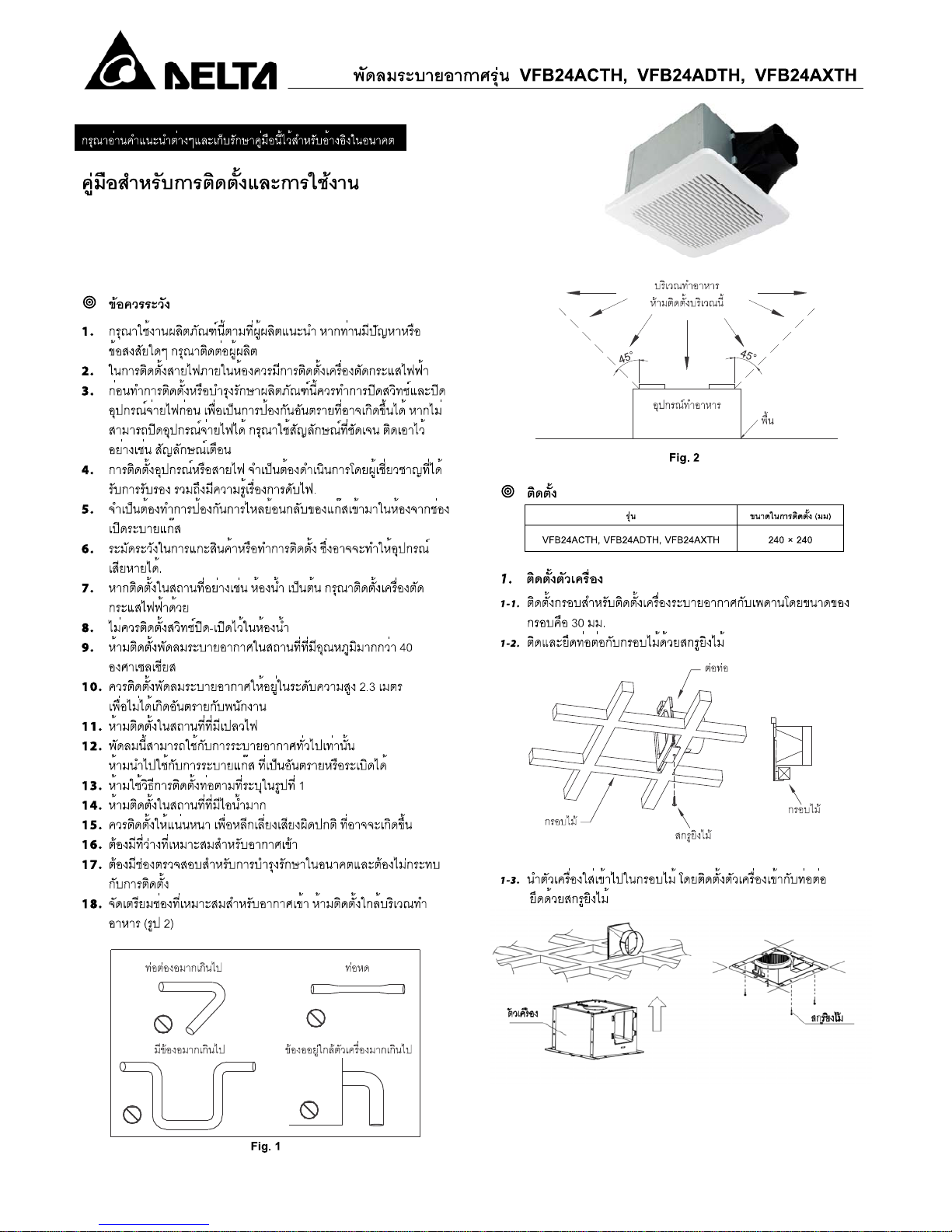
Do not install this product in the place where ducts are
configured as shown in Fig. 1.
Do not install this product in the place with steam.
Install this product securely to prevent from abnormal
sound happen.
An appropriate air intake is required.
Provide inspection and future maintenance access at a
location that will not interfere with installation work.
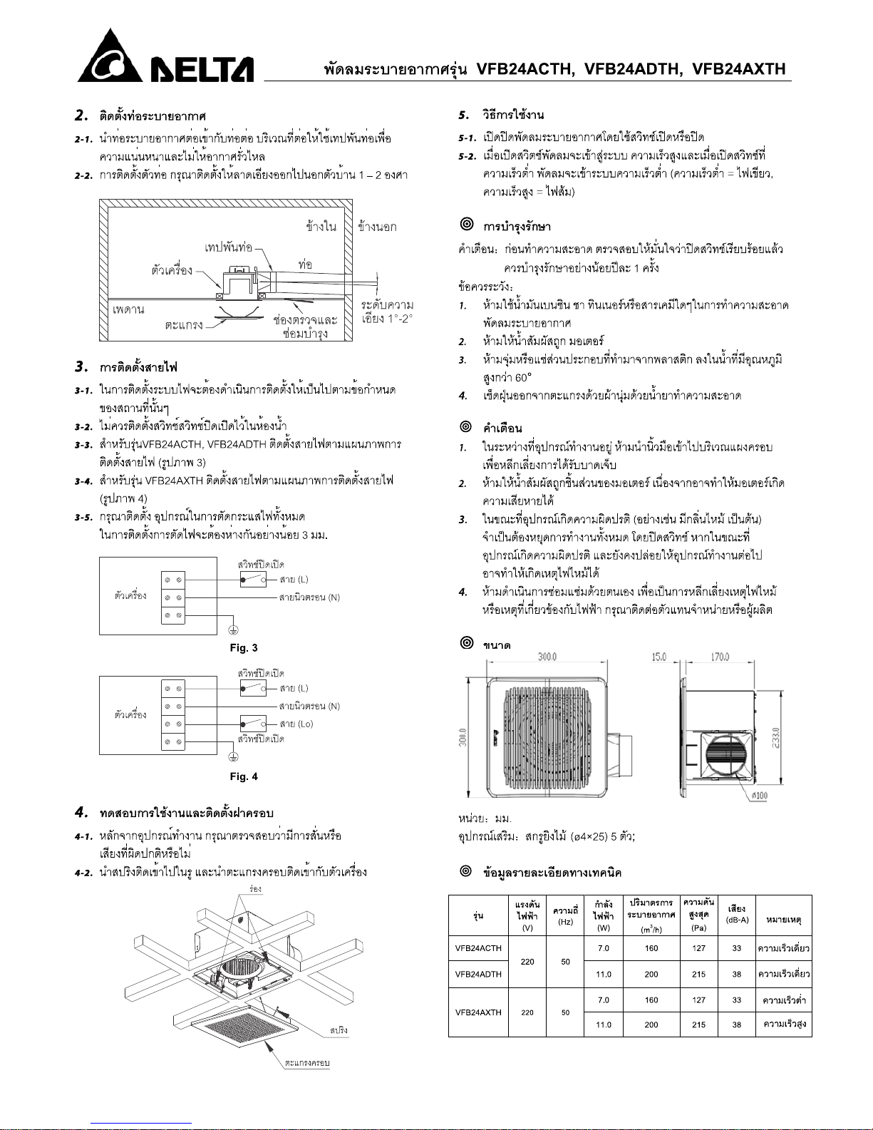
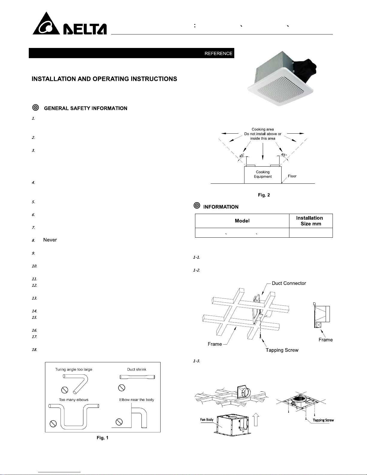
Do not install this product near the cooking equipment.
(Fig. 2)
VFB24ACTH VFB24ADTH VFB24AXTH
240 × 240
1.
Fan Body Installation
Make wooden frame by using 30mm square of wood and
install to the ceiling jo ist.
Install duct connector with wooden frame by using tapping
screws.
Install the fan body into the wooden frame and assemble
with the duct connector. Secure fan body and wooden
frame by using tapping screw.
Page 4

Ventilation Fan Model VFB24ACTH VFB24ADTH VFB24AXTH
2.
Duct Connector
Insert the duct into the duct connector and tape all
ductworks connect ion to make them secure and air tight.
Install the duct with a gradient 1°-2° to the outside.
3.
Connect Wiring
The Follow all local electrical and safety regulation
NEVER place a switch where it can be reached from a tub
or shower
VFB24ACTH, VFB24ADTH connect wires as shown in
wiring diagrams. (Fig.3)
VFB24AXTH connect wires as shown in wiring diagrams.
(Fig.4)
Please install all-poles disconnection device with 3mm
contact gap
4.
Test Run and Grille Attachment
When the product power on, check for abnormal vibration
or sound.
Insert the mounting springs into the slots and mount the
grille to the fan unit
Operation
Turn on the power switch to operate ON or OFF.
When turn on the power, fan will operate in full speed
mode (LED indicator light is AMBER). To change to low
speed mode, turn on the low speed switch and fan will
operate low speed (LED indicator light is GREEN). (Only
for
VFB24AXTH)
WARNING: Disconnect power source before working on unit.
Routine maintenance mu st be d one ev ery year.
CAUTION
Never use petrol, benzene, thinner or any other such
chemicals for cleaning the ventilation fan.
Do not allow water to enter motor.
Do not soak resin parts in water over 60°C
Wipe the dust off the grille with a soft cloth with dampened
non-abrasive kitchen detergent.
When product power on, please do not put your fingers
inside the grille to avoid injury.
Do not spray product with water, which can cause motor
malfunction.
Stop operating and switch off the power when abnormal
situation (burning smell and others). If continue operating
in abnormal situation, it might cause fire due to heati ng and
electric shock.
Repairing should be served by authorized person(s) to
prevent the fire or any electric shock. Please contact with
your dealer or our contact center.
Unit
mm
Supplied accessories: 5 tapping screws (ø4×25)
Model
Voltage
(V)
Frequen
cy (Hz)
Power
Consumption
(W)
Air Flow
(m
3
/h)
Static
Pressure
(Pa)
Noise
(dB)
Remark
VFB24ACTH
220 50
7.0 160 127 33 Single speed
VFB24ADTH
11.0
200 215 38 Single speed
VFB24AXTH
220 50
7.0
160 127 33 Low speed
11.0
200 215 38 High speed
Page 5

VFB24ACTH VFB24ADTH VFB24AXTH
1.
2.
3.
4.
5.
6.
7.
8.
9.
40
10.
2.3
11.
12.
13.
14.
15.
16.
17.
18.
( )
4
5
°
4
5
°
( )
VFB24ACTH VFB24ADTH VFB24AXTH
240 X 240
1.
1-1. 30
1-2.
1-3.
2.
2-1.
2-2.
1 ~2
Page 6

VFB24ACTH VFB24ADTH VFB24AXTH
3.
3-1.
3-2.
3-3. VFB24ACTH, VFB24ADTH
( )
3-4. VFB24AXTH
( )
3-5.
3
4.
4-1.
4-2.
5.
5-1.
5-2.
1.
2.
3.
60
4.
1.
2.
3.
( )
4.
(Ø4 x 25) 5
(V) (Hz) (W) (m
3
/h)
(Pa) (dB)
VFB24ACTH
220 50
7.0 160 127 33
VFB24ADTH 11.0 200 215 38
VFB24AXTH
7.0 160 127 33
11.0 200 215 38
Page 7

Page 8

 Loading...