

Page 1
INSTALLATION & APPLICATION GUIDE
Delta Network Sensor: BACstat I
Product Description
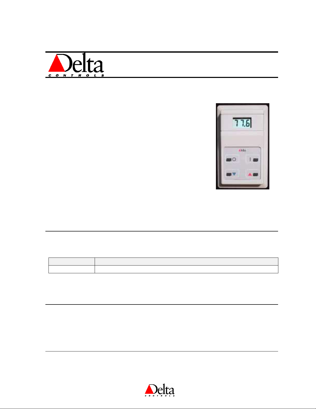
The DNS-14 BACstat I is an intelligent room sensor with four buttons and
a 3-digit LCD display that is used with Delta’s product line of BACnet
Application Controllers. It is capable of communicating on Delta’s
proprietary LINKnet network or directly on a BACnet MS/TP network
using the MS/TP BACnet protocol.
When connected to an Application Controller on a LINKnet network the
DNS-14 provides programmable remote sensor capabilities to the
controller. Up to 12 devices may be connected to the LINKnet network,
depending on the controller, where associated BACnet objects located in
the Application Controller make the DNS-14 accessible to the rest of the
system. These same objects in the Application Controller are used in
programming each DNS-14 for various functions and applications.
DNS-14 (Rev 1.6)
Document Edition 1.9
When connected on an MS/TP network the DNS-14 functions as an independent Native BACnet sensor
device, similar to any other MS/TP device. Each DNS-14 is configured for operation (including the use of its
buttons and display), and can receive commands for mode and setpoint changes from another device across
the network (i.e., DCU or other System Controller with V3.22 firmware).
Model Numbers
Product Number Product Description
DNS-14 Standard Model (with default button template)
The appended button template codes specify the desired icons embossed on the template as follows:
[default] Bottom 2 buttons are ▼ and ▲ (Setpoint Adjust), top 2 are OFF and ON
INT Bottom 2 buttons are ▼ and ▲ (Setpoint Adjust), top 2 are O and I – International
Package Contents
• Delta Network Sensor: BACstat I Product, DNS-14 (Rev 1.6)
• DNS-14 (Rev 1.6) Installation Guide
Document Edition 1.9
Page 1 of 12
Page 2

Delta Network Sensor: BACstat I DNS-14 (Rev 1.6 ) Installation Guide
Other Relevant Documents
• RS-485 Network Installation Guide (DOC818-11)
• ORCAview Operator Guide (V3.21 or later)
• ORCAview Technical Reference Manual (V3.22 or later)
• Release Notes for V3.21 Firmware, V3.22 Firmware, and BACstats
Product Specifications
Power Requirements
• 24 VAC
• 2 VA
• Class II
Ambient Ratings
• 32º to 131º F (0º to 55º C)
• 10 to 90% RH (non-condensing)
Communication Port
LINKnet Connection
• Communications Speed @ 76,800 bps
• Maximum of 12 devices (depending on the controller)
BACnet MS/TP Connection
• Communications Speed @ 9,600 or 19,200 or 38,400 or 76,800 bps (the default)
• Maximum of 99 nodes per MS/TP segment (50 without a repeater)
Input (Temperature Sensor)
• Thermistor Input – 10,000 ohm @ 77 ºF (25 ºC)
• Accuracy of +/- 0.36 ºF from 32 - 158 ºF (+/- 0.2 ºC from 0 - 70 ºC)
• Display Resolution of 0.1 º
• Stability of 0.24 ºF over 5 years (0.13 ºC)
Technology
• 8-bit Processor c/w internal A/D, Flash, and RAM
• 3-digit LCD (7 segment characters)
• 4 momentary push buttons with tactile feedback
Device Addressing
LINKnet Connection
• Set via Keypad Configuration Setup
• Address Range: 1 to 12
BACnet MS/TP Connection
• Set via Keypad Configuration Setup, or Software Setup
• Keypad Address Range: 1 to 99 per network segment
• Software Address Range: As per the BACnet standard
• Supports DNA – Delta’s intuitive addressing scheme
Page 2 of 12
Document Edition 1.9
Page 3
Size
• 4.5” x 2.75”x 1” (11.4 cm x 7 cm x 2.5 cm)
Weight
• 0.16 lb. (71 g.)
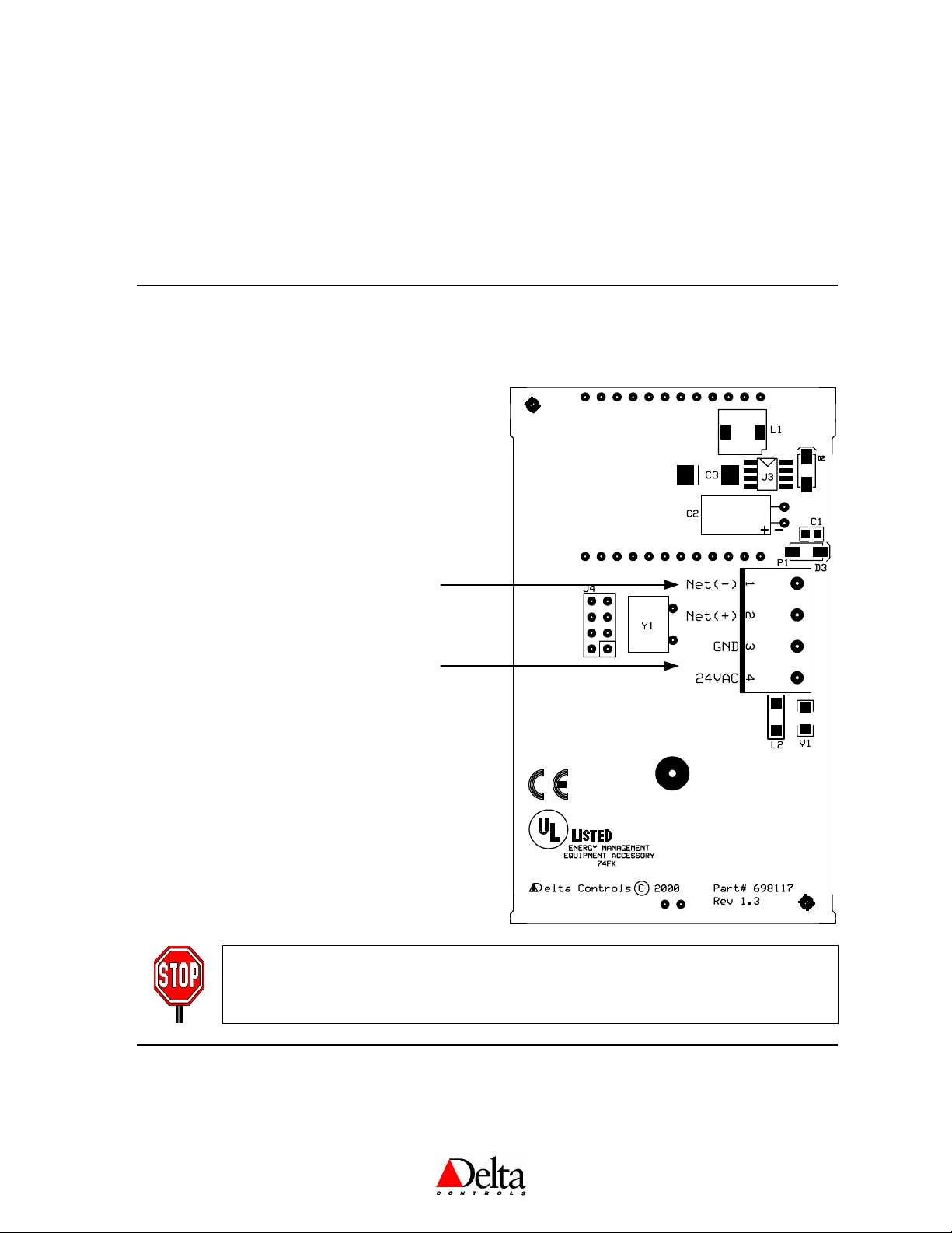
PCB Board Layout & Wiring
Network Notes:
Ensure you use the specified balanced cable
!
and follow documented RS-485 installation
guidelines for MS/TP or LinkNet networks.
Do not terminate the shield on the BACs tat,
!
but ensure conductivity is maintained.
Delta Controls
Network
2-Wire Connection
(MS/TP or LinkNet)
Power
2-Wire Connection
(24 VAC)
Power Notes:
!
If connected to LinkNet, Power may be
supplied from the Power Out port on a DAC
product.
Ensure polarity is observed when the same
!
transformer is connected to more than one
device.
!
If the same transformer is used for more than
one device, ensure it is sized properly.
NOTE: Do not use 4-wire multi-conductor cable. It will not meet the balanced cable
requirements for the MS/TP or LINKnet networks. Use two separate cables: one for
the network and the other for power.
Document Edition 1.9
Page 3 of 12
Page 4
Delta Network Sensor: BACstat I DNS-14 (Rev 1.6 ) Installation Guide
Mounting
The DNS-14 backplate is designed for mounting directly on a standard North American electrical box, but
may be mounted in other ways as well.
Power
The DNS-14 BACstat requires a 24 VAC @ 2 VA power supply, typically an isolated Class II transformer.
More than one device – not including DCUs or V2 products – may be connected to the same transformer,
providing the transformer is properly sized, including line losses, and polarity is observed between controllers
(in regards to 24~ and GND). The transformer must ONLY be used to provide power to other MS/TP or
LINKnet devices. Auxiliary field devices (i.e., 4-20 mA devices) that don’t use ½ wave rectification must be
powered separately.
Network & Cabling Requirements
To ensure network stability and reliable comm unication s, particul arly at h igh speeds on the R S-485 MS/TP or
LINKnet networks, it is imperative that you adhere to the following network and cabling requirem ents:
Item Description
Cabling For MS/TP and LINKnet networks it is recomm ended that you use network cabling that
matches the following specifications:
• Balanced 100 to 120 ohm nomi nal im pedance Tw isted S hi elded Pair (TSP) C able
• Nominal capacitance of 16 PF/FT or low er
• Nominal velocity of propagation of 66% or higher
Topology
Max. Nodes
Termination Boards
For MS/TP and LINKnet networks, ensure th e cable is ins talled as a dais y-chai n f rom one
device to the next.
• MS/TP: The maximum number of devi ces per MS/ TP netw ork w ithout any repeaters is 50.
• LINKnet: The maximum number of dev ices per L INKn et netw ork is 12, depen ding on t he
Application Controller used. Refer to Appendix G in the Technical Refe rence Manual .
• MS/TP: A termination board (TRM-768) must be installed at each end of each MS/ TP
network segmen t – or tw o per MS/ TP or LINK net n etw ork. Ens ure y ou do n ot ov erlook t his
in laying out y our netw ork archit ecture an d ordering produ ct.
• LINKnet: Termination boards need not be installed for only one or two nodes.
However, install a termination board on each end of the network when there are more
than 2 nodes.
Repeater
For more detailed inf orm ation , inclu ding wiri ng, ref er to th e RS- 485 Netw ork Ins tallat ion Gui de (DOC818- 11).
Page 4 of 12
• MS/TP: A repeater (RPT-768) is not necessary unless more than 50 nodes will be installed
on a network or y ou need to ex ten d the n etw ork bey ond 4000 f t (122 0 m ).
• LINKnet: Repeaters should not be necessary. Ensure the maximum distance is no
more than 1000’ (300 m).
Document Edition 1.9
Page 5

Delta Controls
Network Topology
1. BACstats Configured as MS/TP Subnet Devices
With V3.21 firmware or higher, on e possible MS/ TP netw ork arch itecture has the MS/TP devices conf igured as
Subnet devices, allowing BACstats to reside on the MS/TP network with other Subnet devices. Note that
V3.21 requires a DCU, wh ile V3.22 or hi gher m ay us e any System Controller instead.
2. BACstats Configured as LINKnet Devices
The BACstat may reside on LINKnet instead of MS/TP. However, this requires a controller that supports a
LINKnet network for I/O ex pans ion. The m ax imum LINKn et dev ices wi th or wi thout I/ O depends on the
controller.
Network Diagram
ORCAview
OWS
System Devices
DSC-1616EX [DCU]
!
DSC-1616(H/E)
!
!
DSC-1212(H/E)
!
DSC-1280(H/E)
DSC-T305
!
Subnet Devices
16x16 Controller
!
!
12x12 Controller
!
12x8 Controller
!
6x6 Controller
Room Controller
!
VAV/VVT Controller
!
Lighting Controller
!
BACstat I
!
BACstat II
!
(with or without I/O)
Input Field Modules
!
(with V3.22 Firmware)
TRM
PTP
RS-232
RS-485
DCU/DSC
(System Device)
Ethernet Note:
If the DCU or DSC has Ethernet capability, it may exist on an
Ethernet network with other controllers in the same building, on which
the ORCAview OWS could reside as well (instead of PTP).
MS/TP Notes:
1. Ensure you use the recommended balanced cable.
2. Ensure the cable is installed as a daisy-chain from one device to
the next (4,000' or 1220m maximum).
3. Ensure you install an MS/TP terminator board (TRM-768) on each
end of each MS/TP network.
4. The maximum nodes per MS/TP network is 50 without a repeater,
or up to 99 with at least one repeater (RPT-768).
TRM
BACnet (MS/TP) - Level 3 Network (Subnet)
NET1 NET2 NET1 NET2
DAC
(Subnet
Device)
DFM
DAC
(Subnet
Device)
TRM
LINKnet Devices
BACstat I
!
BACstat II
!
(with No I/O)
BACstat II
!
(with muxed I/O)
!
I/O Field Modules
Document Edition 1.9
LINKnet Notes:
1. Ensure you use the recommended
balanced cable.
2. Ensure the cable is installed as a
daisy-chain from one device to the
next. (1000' or 300m maximum).
3. Ensure you install MS/TP terminator
boards when you have more than 1 or
2 devices.
4. Depending on the controller, up to 12
devices are supported on a LINKnet
network, with limitations on how many
of these may have I/O. (Refer to
the Technical Reference Manual.)
Level 4
Network
(LINKnet)
TRM
DFM
Level 4
Network
(LINKnet)
DFM
Page 5 of 12
Page 6

Delta Network Sensor: BACstat I DNS-14 (Rev 1.6 ) Installation Guide
Network Communications Setup
BACstats communicate on an MS/TP network at a default speed of 76,800 bps. Refer to the ORCAview
Technical Reference Manual for further detail on configuring the MS/TP network or changing baud
rates, etc.
On LINKnet, BACstats communicate at 76,800 bps. Refer to the ORCAview Technical Reference
Manual for further detail on the NET1 object located in the MS/TP Application Controller.
Device Configuration
1. Configuration Menu PIN Access Code
Access to the Configuration Menu is protected by an access code or PIN. Y ou mu st enter the v alid PIN before
access is granted, which works as follows:
• First press the Up A rrow (▲), and then press the Down A rrow (▼) while still pressing the Up Arrow, and
hold them both dow n for at l east 5 sec onds .
• When the Pin
4-digit code, which you must enter before y ou can gain acces s to the C onfigu ration Menu. The bu ttons on the
left side of the St at have a v alu e of 0, w hil e the bu tton s on th e righ t side hav e a va lue of 1. Press t he pr oper
button sequence to match the password.
• The default PIN is 1011.
N
OTE
connected to an MS/TP network, but not over LINKnet or through the keypad.
• Once you have entered the valid 4-digit code y ou will gain access to the Configuration Menu, and CFg
displayed immediately to indicate you are now in Configuration mode. If you haven’t entered a valid code (or
if you do not press a button within 10 seconds), the process will be aborted and you will be returned to normal
display m ode.
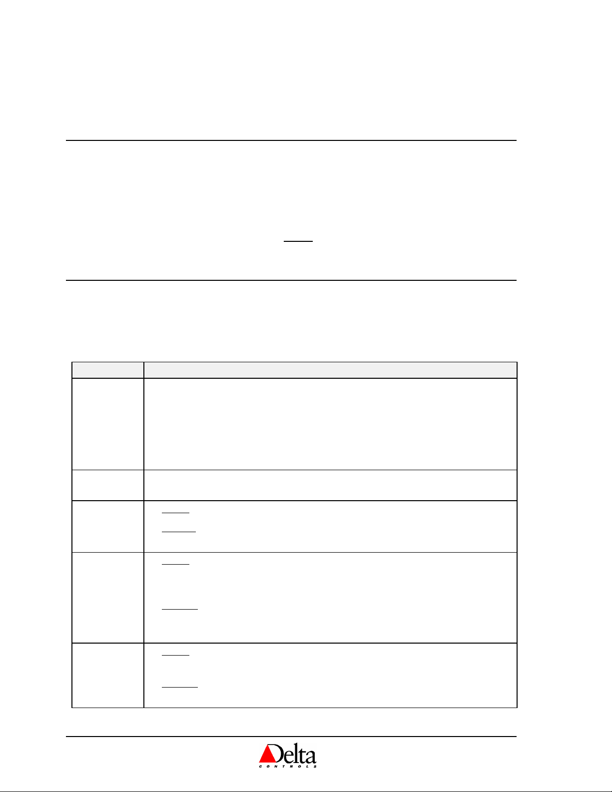
2. Button & Navigation Fun ctions
The Button functions are as follows within the Configuration Menu:
Button Description
Top Left
Top Right
Bottom Left
(Down: ▼)
Bottom Right
(Up: ▲)
Both Arrows
(▼ and ▲)
Pin text is displayed you are being prom pted f or the v alid PIN or acces s code , a pre- conf igured
PinPin
: The PIN access code, contained in AV31, can be ch anged th rough th e OWS when the BACstat is
• Represents a value of 0 when entering the PIN access code.
• E
(or abort) the current setting (and go to the next menu item, without making
SC
any changes).
• Represents a value of 1 when entering the PIN access code.
• E
• Represents a value of 0 when entering the PIN access code.
• Rotates downward through menu items and options.
• Decreases a numeric value with each button press.
• Represents a value of 1 when entering the PIN access code.
• Rotates upward through menu items and options.
• Increases a numeric value with each button press.
• E
the current setting (and go to the next menu item).
NTER
, both simultaneously (an alternate method, particularly necessary for
NTER
2-button models, or when entering the PIN).
CFg will be
CFgCFg
Page 6 of 12
Document Edition 1.9
Page 7

Delta Controls
Use the arrow buttons to navigate through the menu options. Once you have navigated to the desired item you
wish to display or change, w ait a brief m oment f or the curren t value to beg in blink ing, wh ereby you can use the
arrow buttons to make any neces sary chang es. Once th e changes are m ade or y ou w ish to m ove on , press E
3. Configuration Menu Options
The Configurat ion Menu i s a list of ite ms whic h you c an na viga te thr oug h and make c hange s to a s you nee d for
setup purposes . You may use either the down arro w or the up arrow to naviga te through the menu i tems (in
direct or reverse order). Waiting momentarily on an item will eventually display the current setting and allow
you to make changes. The Configuration Menu items are as follows:
Menu Item Description
CFg
CFg
CFgCFg
DEG
DEG
DEGDEG
DSP
DSP
DSPDSP
Lnt
Lnt
LntLnt
dNA
dNA
dNAdNA
Add
Add
AddAdd
BAU
BAU
BAUBAU
SYS
SYS
SYSSYS
ArE
ArE
ArEArE
OEM
OEM
OEMOEM
Displayed momentarily to indicate you have successfully entered the Configuration
Menu.
The Temperature Units Setting (C or F).
The LCD Display Code Setting (AV15) configures lo cal display and button
handling and has the following definitions:
1.0 No Value. The LCD & buttons are fully available for remote programming.
2.0 Local Temperature (AI1) only is always displayed.
3.0 Local Setpoint (AV6) only is always displayed, and can be adjusted.
4.0 Temperature is displayed by default, and pressing an arrow button displays
the Setpoint for adjustment.
5.0 Temperature and Setpoint are alternated on the display every 2 seconds, until
pressing an arrow button displays just the Setpoint for adjustment.
6.0 Setpoint only is always displayed, but cannot be adjusted.
7.0 Temperature is displayed by default, and pressing an arrow button displays
the Setpoint for 3 seconds but cannot be adjusted.
8.0 Temperature and Setpoint are alternated on the display every 2 seconds, but
the Setpoint cannot be adjusted.
N
OTE
: When connected to LINKnet the Display Code should be set to 1.0 (whereby
the display and buttons are controlled through GCL in the host DAC device), while
a setting of 4.0 is a typical choice when connected directly to an MS/TP network.
The LINKnet Communications Setting (On or Off), to match the connection
method. When turned On the network communications is set to LINKnet, and when
Off the communications is set to MS/TP.
The DNA Setting (On or Off), for inheriting a derived address from higher-up
devices on an MS/TP network, or not.
The device Address (1 to 99), which is used internally as the MAC Address. As the
BACstat can only be a Subnet device on MS/TP, this address is always mapped in as
the Subnet value. On LINKnet, this address is the physical address for the device
(limited to 1 to 12) and the other address settings are irrelevant. Note: On MS/TP
the complete BACnet address is in the form of “OEM_Area_System_Subnet”
The System number (0 to 99), which can only be set manually when on MS/TP and
DNA is turned off – and is inherited when DNA is on.
The Area number (0 to 99), which can only be set manually when on MS/TP and
DNA is turned off – and is inherited when DNA is on.
The OEM number (0 to 3), which can only be set manually when on MS/TP and
DNA is turned off – and is inherited when DNA is on.
The Network Speed (9,600 or 19,200 or 38,400 or 76,800 bps). The default for both
LINKnet and MS/TP is 76,800 bps. While the baud rate for MS/TP devices may
need to be adjusted to suite, the speed for LINKnet networks should remain at
76,800 bps.
NTER
.
Document Edition 1.9
Page 7 of 12
Page 8

Delta Network Sensor: BACstat I DNS-14 (Rev 1.6 ) Installation Guide
Menu Item Description
End
End
EndEnd
To exit the Configuration Menu (Yes or No). Otherwise, if you do not press a
button within 1 minute the device will automatically exit and return to its disp lay
mode. All changes are always saved (or set) however you e xit.
Calibration Mode (for the Temperature Sensor Value)
• To enter Calibration mode, first press the Down Arrow (▼), and then the Up Arrow (▲), and hold them
both down for at least 5 seconds. No PIN or access code is required to enter into Calibration mode.
• You may now adjust the calibration of th e temperature f rom -9.9 to 9 9.9 (wh ich acts as a bias to the display
value) using the Down (▼) and the Up (▲) Arrow s.
• Press the E
button sequence to accept the adjusted v alue an d exit Calibration mode.
NTER
Application Notes
OBJECTS
The following is a list of predefined or “fixed” objects that reside in the DNS-14, which you cannot create
or delete. When connected to an MS/TP network, these objects are readily accessible over the network.
When connected to a LINKnet network, many of these objects are mapped into matching AI or AV objects
residing in the Application Controller above.
Object Name Description Default Value
DEV1 BACstat * Device Object N/A
AI1 Temperature Input 1 (10K Thermistor Value) N/A
AV4 KeyPress KeyPress Value N/A
AV5 External * External Object Value (i. e. , OAT) N/A
AV6 Setpoint Room Setpoint ºC = 21; ºF = 71
AV7 Day Min Minimum Adjustable Day Setpoint ºC = 18; ºF = 65;
AV8 Day Max Maximum Adjustable Day Setpoint ºC = 25; ºF = 77
AV13 Alg Mode Algorithm Mode 0 (Off or Night)
AV15 Display Code Local Display & Button Handling 1 (Disabled)
AV16 AI1 Calibration Input 1 Calibration (Temperature) 0.0
AV30 Baud Rate Network Baud Rate 76,800 bps
AV31 PIN PIN (Configuration Access Code) 1011
* Names are User settable (to a maximum of 8 characters)
PROGRAMMING
MS/TP CONNECTION
Objects
All of the predefined objects are readily accessible over the MS/TP network. Note that you can
modify the name of some of the objects to something perhaps more suitable for the application.
Page 8 of 12
Document Edition 1.9
Page 9

Delta Controls
GCL Programming
BACstats are not programmable devices – GCL does not reside in a BACstat. Rather, when
connected to an MS/TP network you configure a BACstat for local operation and write GCL located
elsewhere as necessary to do additional functions. In this way you configure the BACstat for local
operation (both displ ay & button handling and local control) and then write any necessary GCL in
another controller for additional strategies.
For example: Through the Configuration Menu, you typically configure the DN S-14 display and
buttons to functional locally, so GCL programs are not necessary for handling the display value or
adjusting setpoint (i.e., AV15 = 4.0). Then, using GCL programming located in another controller
(i.e., DCU or other System Device) you make mode and setpoint changes based on Time-of-Day or
other conditions.
W
ITH
V3.21 F
IRMWARE
: All GCL programming for mode changes, data exchange, and other
strategies must be written in the DCU.
W
ITH
V3.22 F
IRMWARE OR HIGHER
: A DCU is no longer necessary and since data exchange is
supported across MS/TP-based products, no specific GCL is required for this. GCL programming
for mode changes or other strategies may be written in any appropriate controller on the network.
Refer to Appendix G in the V3.22 ORCAview Technical Reference Manual for further programming
information.
LINKNET CONNECTION
Device Limitations
Note that there are inherent limitations to the total number of devices per LINKnet network, as well
as the number of devices that have outputs. Refer to Appendix G in the V3.22 ORCAview Technical
Reference Manual for further information.
Objects
Only the BACstat information that is represented by objects reside nt in the Applicatio n Controller is
readily accessible over the network. The objects resident within each BACstat are not directly
accessible to other devices in the system. To gain access to BACstat objects, you create objects in
the Application Controller that correspond to the objects located in its respective BACstats.
Object Name Description Creation
LCDx01 LinkLCD# Object for BACstat LCD & Button Presses Automatic
AIx01 [User Specified] Object for the 10K Temperature Value Manually
Avx01, 02, etc. [User Specified] Matching object for the corresponding AV Manually
where “x” refers t o the device address (1 to 12) multiplied by 1 00.
An LCD object is automatically created for each BACstat connected to the LINKnet network.
However, the associated AI objects representing the room temperature in each BACstat must be
created manually, and must follow a predefined numbering scheme. The object instance number is
the LINKnet device address (1 to 12) multiplied by 100, plus 1. For example, you would create
AI501 in the Application Controller to represent the 10K thermistor value on a BACstat with a
LINKnet device address of 5.
With V3.22 loaded in the Application Controller, AV objects may be created in a similar fashion to
the AI objects, which map to corresponding AV objects in the BACstat. You can then use these in
GCL programming as well. With V3.21, mapped AV objects are not supported.
Document Edition 1.9
Page 9 of 12
Page 10

Delta Network Sensor: BACstat I DNS-14 (Rev 1.6 ) Installation Guide
GCL Programming
All GCL programming for BACstats on a LINKnet network is written in the Application Controller
that the BACstats are connected to, using the mapped objects resident in the Application Controller.
The LCD object is used for display and button handling. The mapped AI1 object is used for reading
the temperature value. And with at least V3.22 firmware on the Application Controller, the mapped
AV objects are used for setpoints and various other settings.
Note: Always use the LCD object for processing button presses over a LINKnet connection,
rather than AV4.
W
ITH
V3.21 F
IRMWARE
: When connected to LINKnet local display and button handling should be
disabled (i.e., AV15 = 1.0), which is the default when you set the LINKnet Communications Setting
. This way, the LCD and buttons are fully accessible from the Application Controller for
N
to O
custom programming. Then, with GCL and the LCD and AI objects resident up in the Application
Controller, you program the BACstat to operate as you want (similar to how ISTATs were
programmed) – all BACstat functionality is written in GCL located in the Applicatio n Controller.
Note that none of the AV objects are accessible with V3.21 firmware.
W
ITH
V3.22 F
IRMWARE OR HIGHER
: You may disable local display and button handling (i.e.,
AV15 = 1.0) and program everything in GCL in the Application Controller as previously described
for V3.21 firmware. Or, by setting the Display Code to something other than 1.0 (i.e., 4.0, which is
a typical setting), the display and buttons may be configured to function locally and GCL commands
from the Application Controller for display and button handling (via the LCD object) are ignored.
This may be the preferred method as no GCL needs to be written to handle setpoint adjust and the
display of values on the LCD. In addition to this, setpoints and other setti ngs are also accessible
through their corresponding AV objects.
Refer to Appendix G in the V3.22 ORCAview Technical Reference Manual for further programming
information.
Page 10 of 12
Document Edition 1.9
Page 11

Cautions and Warnings
Delta Controls
WARNING
The DNS-14 BACstat is an Electro-statically sensitive device. However, since the electronics
are contained within the housing, and if sufficient care is taken in handling, proper ESD
protection (ground strap) should be unnecessary.
Compliance Declarations
FCC Compliance Information
This equipment has been tested and found to comply with the limits for a Class B digital device, pursuant to
Part 15 of the FCC Rules. These limits are designed to provide reasonable protection against harmful
interference in a residential installation. This equipment generates, uses, and can radiate radio frequency
energy and, if not installed and used in accordance with the instructions, may cause harmful interference to
radio communications. However, there is no guarantee that interference will not occur in a particular
installation. If this equipment does cause harmful interference to radio or television reception, which can be
determined by turning the equipment off and on, the user is encouraged to try to correct the interference by one
or more of the following measures:
• Reorient or relocate the receiving antenna.
• Increase the separation between the equipment and receiver.
• Connect the equipment into an outlet on a circuit different from that to which the receiver is
connected.
• Consult the dealer or an experienced radio/TV technician for help.
Industry Canada Compliance Statement
ICES-003 This Class B digital apparatus meets all requirements of the Canadian Interference-Causing
Equipment Regulations.
Cet appareil numérique de la Classe B Respecte toutes les exigences du Règlement sur le matérial
brouiller du Canada.
UL Compliance Information
This product conforms to the following UL requirements:
•
UL916: Energy Management Equipment
Document Edition 1.9
Page 11 of 12
Page 12

Delta Network Sensor: BACstat I DNS-14 (Rev 1.6 ) Installation Guide
CE - DECLARATION OF CONFORMITY
according to ISO/IEC Guide 22 and EN 45014
Manufacturer's Name: Delta Controls
Manufacturer's Address: 17850 56th Avenue
Surrey, British Columbia
Canada
V3S 1C7
declares that the product (s):
Product Name: BACstat I
Model Numbers: DNS-14
Product Options: All
conforms to the following Product Specifications:
EMC:
EN 55022:1994 Radiated and Conducted Emissions Class B
EN 50082-1:1997 Generic Immunity Standard
EN 61000-4-2:1995 + A1:1999 ESD Immunity Level A
EN 61000-4-3:1996 RF Electromagnetic Field Immunity Level A
ENV 50204:1995 RF Electromagnetic Field Immunity (Keyed) Level A
EN 61000-4-4:1995 EFT/Burst Immunity Level B
EN 61000-4-5:1995 Surge Immunity Level B
EN 61000-4-6:1996 Conducted RF Disturbances Immunity Level A
EN 61000-4-11:1994 Voltage Dips / Interruptions Level B/C
Supplementary Information:
The product(s) herewith comply with the requirements of the EMC Directive
89/336/EEC. The product(s) were tested in a typical configuration.
Lee Dickson
Quality Assurance Manager
Page 12 of 12
Document Edition 1.9
 Loading...