

Page 1

INSTRUCTION MANUAL
Unifence
TM
Saw Guide
30 " C a p acity
(Model 36-905)
REVISED: 10-27-98 PA RT NO. 422-27-655-0053
'Delta International Machinery Corp. 1998
Page 2

2
TABLE OF CONTENTS
INTRODUCTION...............................................................................................................................................................2
UNPACKING.....................................................................................................................................................................3
CONSTRUCTING UNIFENCE TABLE.............................................................................................................................3
ASSEMBLING LEGS AND FRONT TABLE SUPPORT..................................................................................................4
ASSEMBLING TABLE ADAPTER PLATE TO SAW TABLE..........................................................................................5
ASSEMBLING UNIFENCE TABLE TO SAW ..................................................................................................................6
ASSEMBLING UNIFENCE GUIDE RAIL TO TABLE......................................................................................................7
ASSEMBLING REAR EXTENSION WING SUPPORT BAR .........................................................................................12
ASSEMBLING CURSOR TO UNIFENCE BODY ..........................................................................................................13
ASSEMBLING UNIFENCE BODY TO GUIDE RAIL .....................................................................................................13
ASSEMBLING FENCE TO UNIFENCE BODY..............................................................................................................14
FENCE OPERATION......................................................................................................................................................15
RIPPING WITH THE UNIFENCE ...................................................................................................................................16
ADJUSTING FENCE PARALLEL TO MITER GAGE SLOTS .......................................................................................17
ADJUSTING FENCE 90 DEGREES TO TABLE...........................................................................................................17
ADJUSTING CLAMPING ACTION OF FENCE LOCKING HANDLE...........................................................................17
RIPPING ON LEFT SIDE OF SAW BLADE ..................................................................................................................18
USING THE FENCE AS A C U T-OFF GAGE .................................................................................................................18
USING AUXILIARY WOOD FACING ON THE UNIFENCE...........................................................................................19
CONSTRUCTING A PUSH STICK.................................................................................................................................19
PARTS, SERVICE OR WARRANTYASSISTANCE......................................................................................................20
W ARRANTY...................................................................................................................................................................20
INTRODUCTION
The model 36-905, 30 cap acity UnifenceTMSaw Guide can be assembled to the Delt a 10 Contractor s
Saw; 10 Tilting Arbor Saw and 10 Unisaw in addition to other makes of t able saws. The 36-905
UnifenceTMSaw Guide includes the fence, carriage assembly, front guide rail, t able frame, legs and shelf
support. The accessory 34-914 table is not included with the 36-905 UnifenceTM Saw Guide and must be
ordered separately or a similar t able must be constructed by following the instructions in this manual.
Page 3
3
UNPACKING
Carefully unp ack the Unifence and all loose items from the shipping cartons. NOTE: Do not discard the card board template shipped with the Unifence as it will be used in the assembly.
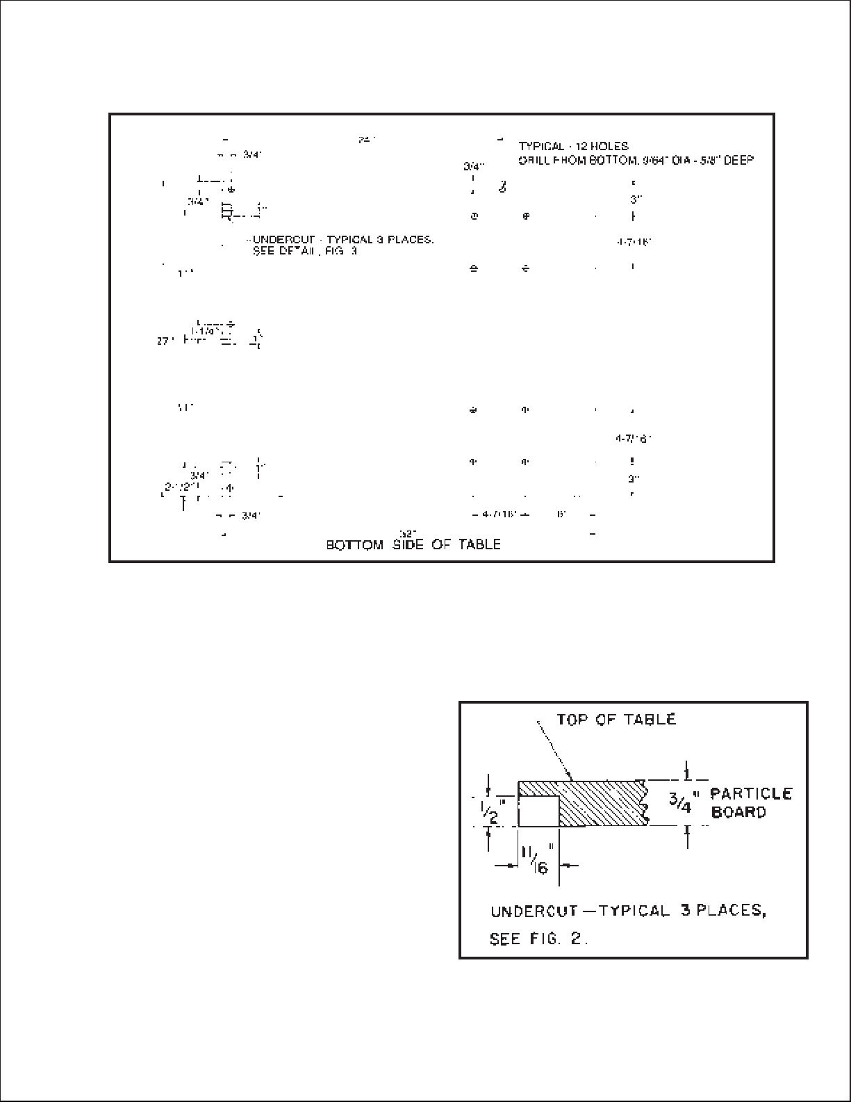
If you purchased the 36-905 Unifence without the acces sory 34-914 t able, a similar t able must be constructed,
preferably of p article board.
1. A 32 long by 27 wide t able should be constructed
using 3/4 inch material by following the dimensions
shown in Fig. 2.
2. T welve 9/64 inch diameter holes must be drilled
5/8 inch deep in the bottom side of the t able. These
twelve hole locations are shown in Fig. 2.
3. Three undercuts must also be made on the bottom
lef t side of the t able. The location of these undercut s are
shown in Fig. 2. The size of the undercuts are shown in
det ail in Fig. 3. NOTE: On saws other than Delt a, it may
be necessary to change the location of the three under cut s in the t able depending on the position of the table
adapter plate mounting screws. Refer to section
ASSEMBLING TABLE ADAPTER PLATE TO SAW
TABLE.
4. IMPORTANT: For maximum operational ease when
sliding the fence across the t able, the top of the t able
should be covered with a veneer.
Fig. 2
CONSTRUCTING UNIFENCE TABLE
Fig. 3
Page 4
4
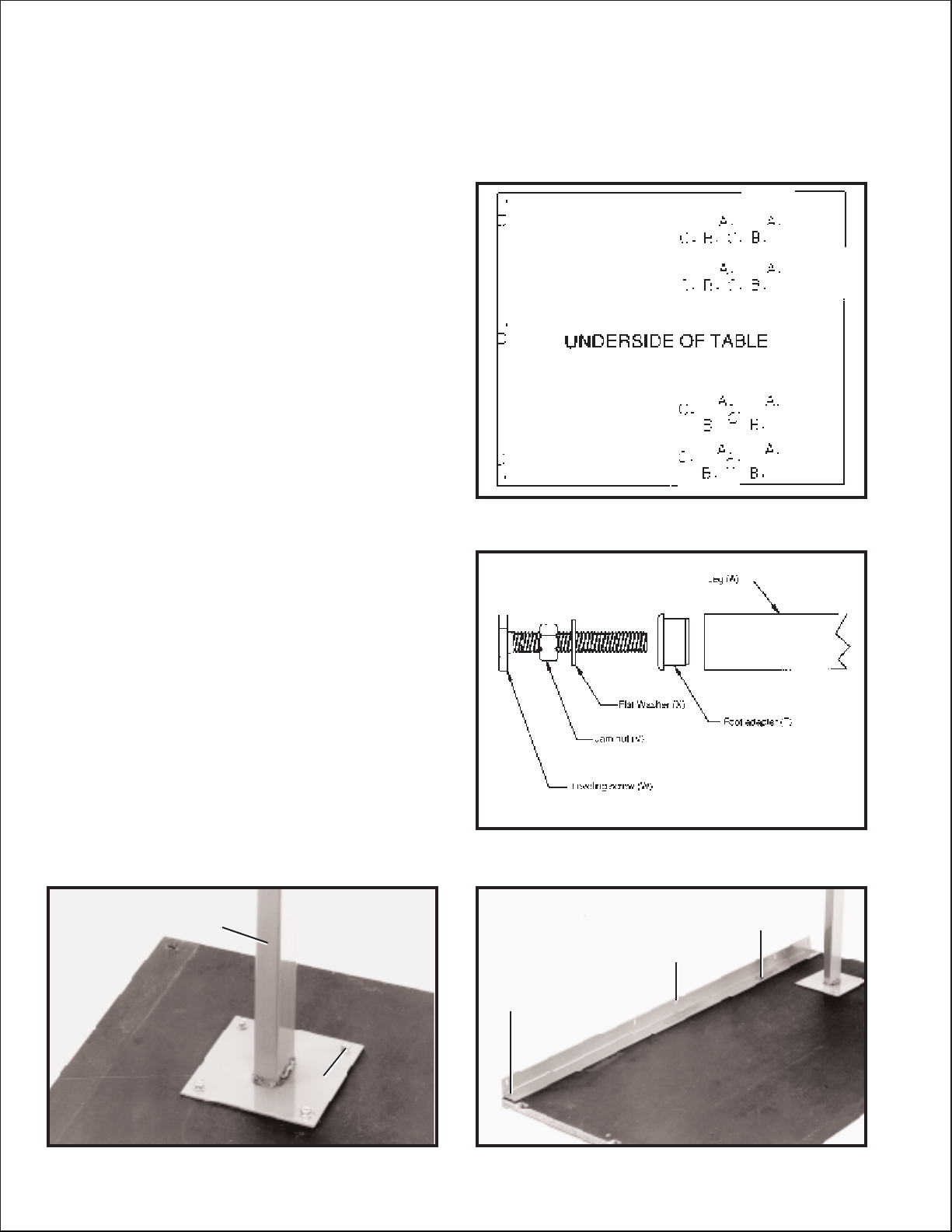
Fig. 4
ASSEMBLING LEGS AND FRONT TABLE SUPPORT
1. Lay the t able up side down on the floor or bench.
2. If you purchased the 36-905 Unifence with the accessory 34-914 t able, three set s of holes have been
predrilled in the underside of the t able to assemble the t able legs. NOTE: These hole patterns will allow the
table legs to be set correctly if you are using Delt a Mobile Bases and Mobile Base Table Extensions.
A. Eight holes indicated as (A) Fig. 4, beginning 6
inward from the end of the t able, are used to
mount the legs when assembling the t able to a
Delt a 10 Contractor s S aw.
B. Eight holes indicated as (B) Fig. 4, beginning
7-3/8 inward from the end of the t able, are used
to mount the legs when assembling the t able to
Delt a Unisaw.
C. Eight holes indicated as (C) Fig. 4, beginning
9-5/8 inward from the end of the t able, are used
to mount the legs when assembling the t able to a
Delt a 10 T ilting Arbor Saw.
Fig. 5
Fig. 7Fig. 6
3. Before assembling the legs to the t able, insert the
foot adapter (T) Fig. 5, into the bottom of each leg (A).
Assemble the 3/8-16 jam nut (V) approximately 3/4 of the
way onto leveling screw (W) and place a flat washer (X)
over the jam nut (V) as shown in Fig. 5. Thread the leve ing screw (W) into foot adapter (T); height adjustment s
can be made later.
4. Assemble leg (A) Fig. 6, to the bottom of the t able
using four #14 x 3/4 inch-long screws (B) as shown.
Assemble the remaining leg to the t able in the same
manner.
5. Fasten the front t able support (D) Fig. 7, to the bot tom of the t able as shown, using two #14 x 3/4 inch-long
screws (E) and (F) supplied. NOTE: The slots closer to
the bend in the support should be against the t able. Do
not completely tighten the two screws at this time.
IMPORTANT: SCREW (E) MUST BE REMOVED A N D
REINSTALLED WHEN ASSEMBLING UNIFENCE
TABLE TO SAW (REFER TO PAGE 6).
A
B
E
D
F
Page 5
5
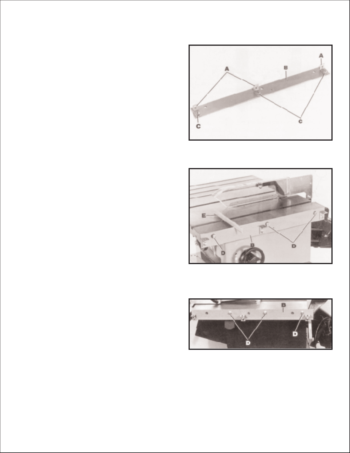
Fig. 8
Fig. 9
ASSEMBLING TABLE ADAPTER PLATE
TO SAW TABLE
Fig. 10
1. Assemble three bracket s (A) Fig. 8, to t able adapter
plate (B) using three 1/4-20 x 3/4 inch-long carriage
bolt s, flat washers and hex nut s (C). Do not completely
tighten hardware at this time as adjustment s must be
made.
FOR DELTA TABLE SAWS ONLY
2. Assemble t able adapter plate (B) Fig. 9, to the right
side of the saw t able using three 7/16-20 x 1 inch-long
hex head screws (D) and lockwashers. NOTE: Before
tightening screws (D), place a straight edge (E) on the
saw t able, and make cert ain the top of adapter plate (B)
is level with or slightly below the surface of the saw
table. Also, make certain the front of adapter plate (B)
does not extend out p ast the front edge of the saw t able.
IMPORTANT: FOR DELTA S AW S O N LY, PROCEED
WITH SECTION ASSEMBLING UNIFENCE TABLE
TO SAW .
FOR TABLE SAWS OTHER THAN DELTA
3. Assemble t able adapter plate (B) Fig. 10, to the right
side of the saw t able as shown using three 3/4 inch
screws, lockwashers and hex nut s (D), (not supplied).
IMPORTANT: If the pre-drilled holes in adapter plate (B)
do not line up with the holes in the saw t able, new holes
must be drilled in adapter plate (B) and/or saw t able.
NOTE: Do not drill any hole to fasten adapter plate (B)
Fig. 10, to the saw t able that will be located less than two
inches from either end of the adapter plate.
4. Before tightening three screws (D) Fig. 10, place a
straight edge on the saw t able and make cert ain the top
of adapter plate is level with or slightly below the surface
of the saw t able, refer to Fig. 9. Also, make cert ain front
of adapter plate (B) Fig. 10, does not extend out p ast the
front edge of the saw t able.
Page 6
6
Fig. 1 1
Fig. 12
Fig. 14Fig. 13
Fig. 15
F
K
H
M
L
ASSEMBLING
UNIFENCE TABLE
TO SAW
1. Remove #14 x 3/4 inch-long screw (E) Fig. 12, which
was inst alled in STEP 5, p age 4.
2. Assemble Unifence t able (A) Fig. 1 1, to bracket s (B)
using two #14 x 3/4 inch-long screws (D) and screw (E)
which was removed in STEP 1, Fig. 12. NOTE: The two
screws (D) Fig. 12, can be tightened; screw (E) should
be lef t slightly loose at this time. CAUTION: Overtightening screws in p article board may cause them to strip.
3. Using a straight edge (F) Fig. 13, make cert ain the
Unifence t able surface is level with the saw t able by
adjusting two leveling screws on bottom of t able legs and
adjusting bracket s (B) Fig. 14. Then tighten three nut s
(C) Fig. 14. IMPORTAN T: Front edge of Unifence table
must be flush with or slightly behind front edge of saw
table.
4. Place the shelf support (H) Fig. 15, against t able legs
and fasten with U-bolt s (K), flat washers (L), and hex
nuts (M) as shown.
Page 7

7
Fig. 16
5. Fig. 16, illustrates the shelf support (H) assembled to
the t able legs. NOTE: Shelf support (H) can be rot ated or
adjusted to fit any type of shelf.
6.After the t able and legs are assembled to the saw ,
check if the Unifence t able is level with the saw t able. If
an adjustment is necessary, loosen jam nut (P) Fig. 16,
and rot ate leveling screw (R) as necessary. T ighten jam
nut (P) against bottom of each t able leg.
ASSEMBLING UNIFENCE GUIDE RAIL TO TABLE
1. MAKE CERTAIN THE TABLE SAW IS DISCONNECTED FROM THE POWER SOURCE.
2. Remove the fence, guide rails, right hand extension wing and blade guard assembly from the t able saw.
IMPORTANT: THE BLADE GUARD ASSEMBLY MUST BE RE-ASSEMBLED TO YOUR TABLE SAW
AFTER THE UNIFENCE ASSEMBLY IS COMPLETED. NOTE: If you are assembling the Unifence to a Delt a
10 Contractors S a w, assemble the extension wing support bar supplied with the Unifence, to the rear of the
lef t extension wing and saw t able. (Refer to p age 12 of this manual).
3. Raise the saw blade to it s maximum height and make sure the blade is 90 degrees to the t able. NOTE:
If you are assembling the Unifence to a Delt a Table Saw, proceed to STEP 13.
Fig. 19
Fig. 18
FOR TABLE SAWS OTHER THAN DELTA
4. Locate p aper template (A) Fig. 17, included with the
instructional literature and identified as p art no. 422-27655-0009.
5. Fold p aper template (A) along the line marked t able
top and place it on the saw t able with the fold along the
top front edge of the t able, as shown in Fig. 18.
6. Position a straight edge (B) Fig. 19, along the right
side of the saw blade with one end of the straight edge
extending out to the front of the saw t able over the tem plate (A) as shown.
H
P
R
P
R
Fig. 17
A
A
A
B
Page 8

8
Fig. 20
Fig. 21
Fig. 22
Fig. 23
7. Slide template (A) Fig. 20, lef t or right, along the t able
until the line (C) on the template marked lineup with right
side of blade is aligned with the lef t edge of the straight
edge (B). Make sure the fold in the template is along the
top front edge of the t able and t ape the template to the
table.
8. Check to see if the two holes (D) Fig. 21, illustrated
on the template match the holes on the front edge of your
saw t able.
A. If the location of the holes in your saw t able
match the holes (D) Fig. 21, illustrated on the tem plate and are 7/16 in diameter , remove the template
and proceed to STEP 13. IMPORTANT: IF HOLES
IN FRONT OF SAW ARE THREADED, THEY MUST
BE DRILLED OUT.
B. If the location of the holes in your saw t able
match the holes (D) Fig. 21, illustrated on the
template but are not 7/16 in diameter, remove the
template and enlarge the holes in the t able by drilling
them out. Then proceed to STEP 13.
C. If the location of the holes in your saw t able do
not match holes (D) Fig. 21, illustrated on the tem plate, it will be necessary to drill two new 7/16 diam eter holes in the saw t able at locations indicated at
(D), on the template, providing structural ribs or
existing holes in the t able do not interfere with the
two new holes. Center punch to locate the two new
holes to be drilled and remove the template. Drill the
two new 7/16 diameter holes in the table and pro ceed to STEP 13.
D. If structural ribs or existing holes in the saw t able
prevent drilling holes at the locations shown on tem plate at (D) Fig. 22, it will be necessary to move one
or both of the holes, making sure the new holes are
on the same center line as holes (D). Mark the loca tion of new hole(s) (E) on the template, as shown in
Fig. 22. Center punch the location of the new hole(s),
remove the template, drill the new hole(s) in the t able
and proceed to STEP 9.
9. Cut the template along the line marked 0 (zero on
guide rail scale), as shown in Fig. 23.
C
B
A
D
D
D
E
Page 9

9
Fig. 24
Fig. 25
Fig. 26
Fig. 27 Fig. 28
10. Fold the top portion of the template toward you in the
line marked top of guide rail (F), as shown in Fig. 24.
11. Position the template on the guide rail, as shown in
Fig. 25, with the printed side of the template against the
guide rail and the fold in the template along the top of the
rail. Position the template so that edge (G) which was cut
in STEP 9 is aligned with the 0 mark on the scale, as
shown. Tape the template in place on the guide rail. Hole
(H) Fig. 25, indicates the hole that was drilled in the t able
in STEP 8D and is the location of the new hole to be
drilled in the guide rail.
12. Center punch the location of the new hole(s) (H)
Fig. 26, to be drilled in the guide rail, as shown. Remove
the template and drill the new 7/16 diameter hole(s) in
the back of the guide rail.
FOR ALL TABLE SAW S
IMPORTANT: If the mounting holes in the front of the
table saw are threaded, the threads must be drilled out to
7/16 inch thru holes.
13. The guide rail (N) Fig. 27, has end cap s, one of
which is shown at (W), inserted into each end of the rail.
Remove the lef t end cap (W) Fig. 28, by inserting a flat
headed screwdriver (X) into the channel in front of the
guide rail and press outward against the inside of the end
cap (W) as shown. The end cap (W) will pop out. NOTE:
DO NOT ATTEMPT TO REMOVE THE END CAP B Y
FORCING THE SCREWDRIVER BETWEEN THE END
C A P AND THE END OF THE RAIL. THIS WILL D A MAGE BOTH THE CAP AND THE RAIL.
F
H
G
H
A
B
A
Page 10

10
Fig. 29
Fig. 30
Fig. 31
Fig. 32
14. Locate the cardboard template (K) Fig. 29, from the
packing material of the Unifence.
15. Place the two 3/8 - 24 hex nut s, one of which is
shown at (J) Fig. 29, in position on the two t abs on the
cardboard template (K).
16. Insert cardboard template (K) into channel in end of
guide rail, as shown in Fig. 29, until the hex nut s, one of
which is shown at (J), line up with the mounting holes in
the rail.
17. Locate the two double threaded studs (L) Fig. 30,
packed with the Unifence and thread the short fine
threads of the studs (L), into the two hex nut s inside the
channel of the guide rail, as shown.
18. Assemble the guide rail to the saw t able by inserting
two studs (L) Fig. 31, into the two matching holes in the
front edge of the t able and fasten using two flat washers
and hex nut s (M). Only snug up two hex nut s (M), at this
time.
19. Adjust the guide rail (N) Fig. 32, p arallel with the saw
table surface by placing a square (O), on the saw t able
at both the lef t and right front end of the t able, with rule
of square against flat surface on top of guide rail, as
shown. The guide rail (N) can be moved up or down at
either end. Af ter you are cert ain the flat surface of the
guide rail is p arallel with the t able surface, firmly tighten
the two hex nut s that fasten the guide rail to the t able.
NOTE: For all saws other than Delt a Series 2000
Contractor s Saws, continue with STEP 23.
K
J
L
L
L
M
M
L
O
N
V
Page 11

11
SWITCH MOUNTING FOR DELTA SERIES 2000
10 CONTRACTOR S SAW S EQUIPPED WITH
MODEL NO. 36-905 30 C A PACITY UNIFENCE
Fig. 33
Fig. 34 Fig. 35
20. The ON/OFF switch (X) Fig. 33, for the Delt a Series
2000 10 Contractor s Saw is mounted to the lef t exten sion wing (V) as shown.
21. Fasten the ON/OFF switch (X) Figs. 33 and 34, to
guide rail (N) using 1/4-20 x 1 long screw and flat wash er (S). Do not completely tighten screw at this time.
22. Using a square (O) Fig. 35, adjust the extension
win g (V) p arallel to saw t able (Y), then tighten screw (S)
Fig. 34.
V
X
N
X
N
S
Y
V
O
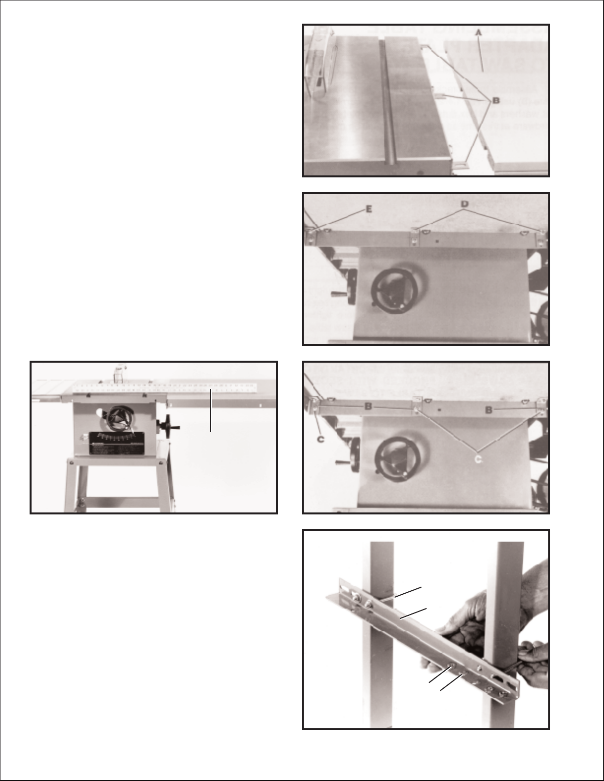
Fig. 36
FOR ALL TABLE S AW S
23. Fasten the guide rail (N) Fig. 36, to extension wing
(V) by threading 1/4-20 x 5/8 inch-long screw (S) Fig. 36,
with flat washer through slotted hole in the front of exten sion wing (V), and into threaded hole in guide rail (N) as
shown.
S
V
N
Page 12

12
F OR ALL DELTA S AW S EQUIPPED WITH
STAMPED STEEL EXTENSION WINGS
ASSEMBLING
REAR EXTENSION WING
SUPPORT BAR
1. Assemble rear extension wing support bar (A)
Fig. 40, to the saw t able and extension wing, using three
3/8-16 x 1 long hex head screws, flat washers, and hex
nut s (B ).
BB
A
Fig. 37
Fig. 38
Fig. 39
Fig. 40
24. Move front t able support (R) Fig. 37, until it cont act s
the back of guide rail (N) and fasten with 1/4-20 x 5/8
inch-long screw and flat washer (S).
25. T ighten two screws (T) Fig. 38, that fasten t able to
front t able support (R).
26. Replace end cap (W) Fig. 39, that was removed in
STEP 13.
S
N
R
T
R
T
Page 13

13
Fig. 41
Fig. 42
Fig. 43
Fig. 45Fig. 44
FOR ALL TABLE S AW S
ASSEMBLING CURSOR
TO UNIFENCE BODY
1. Remove two screws and flat washers (A) Fig. 41,
and assemble the cursor (B) to the Unifence body (C).
Replace the two screws and flat washers (A).
2. Fig. 42, illustrates the cursor (B) assembled to the
Unifence body. Adjustment to the cursor (B) will be made
later.
ASSEMBLING UNIFENCE
BODY TO GUIDE RAIL
1. T urn fence body (A) Fig. 43, up side down and lay it
on a table or bench. Push handle (B) in against fence
body. Make cert ain the surface (C) of clamp bracket is
p arallel to the face (D) of the fence body , and that
the inside edge (E) of the clamp bracket is p arallel to
surface (F) of the fence body. T urn handle (B) Fig. 43, if
necessary.
2. Place fence body (A) Fig. 44, onto the guide rail as
shown, making sure clamp bracket is inserted into chan nel (G) on rail. Notice that the clamp handle (B) is turned
to the lef t indent position.
3. T urn handle (B) Fig. 45, to the right indent position as
shown. This will prevent fence clamp from sliding out of
the channel (G).
B
C
A
B
D
A
B
C
E
F
A
B
G
B
G
Page 14

14
Fig. 46
Fig. 47
Fig. 48
Fig. 49
4. Lock fence body (A) to the guide rail by pushing
down on handle (B) as shown in Fig. 46.
ASSEMBLING FENCE
TO UNIFENCE BODY
1. The fence (A) can be assembled to clamp plate (B)
in either the horizont al position as shown in Fig. 47, or
the vertical position as shown in Fig. 48. Make cert ain the
two lock knobs (C), are loose and slide fence (A) onto
clamp plate (B) as shown. Then tighten the two lock
knobs (C).
2. For most normal ripping operations, the bottom of
the fence should be positioned slightly above the t able
surface. Loosen two lock knobs (C) Fig. 49, and place a
thin object such as a ruler (D) between the t able and
fence, as shown. Then tighten two lock knobs (C).
A
B
A
B
C
C
D
Page 15

15
Fig. 50
Fig. 51
Fig. 52
Fig. 54Fig. 53
FENCE OPERATION
1. Before operating fence, make sure the fence is
adjusted p arallel to miter gage slot, as explained later on
in this manual.
2. For most normal ripping operations of st andard size
lumber the fence is used in the vertical position, as
shown in Fig. 50.
3. When ripping thin stock, it is sometimes more con venient to use the fence in the horizont al position, as
shown in Fig. 51.
4. To move the fence along the guide rail, simply lif t up
clamp lever (A), as shown in Fig. 52, slide fence to
desired position on the rail, and push down on clamp
lever (A) to lock fence in place.
5. The dist ance the fence is positioned away from the
blade is indicated by the two witness lines (B) and (C)
Fig. 53, located on the cursor (D). The witness lines (B)
and (C) easily indicate the dist ance the fence is posi tioned away from the saw blade. W itness line (B) indi cates the dist ance the fence is away from the blade when
the fence is in the horizont al position, and witness line
(C) indicates the dist ance the fence is away from the
blade when the fence is in the vertical position. If it is
necessary to adjust cursor (D), make a test cut with the
fence in either the vertical or horizont al position, measure the dist ance of the finished cut and move the cursor
(D) by loosening the two screws (E) Fig. 53. Af ter adjust ment is completed tighten the two screws (E).
6. To remove the fence and fence body assembly (F)
Fig. 54, from the guide rail, lif t up on fence clamping lever
(A) and turn lever (A) to the lef t indent position. The fence
assembly (F) can then be pulled straight of f the guide rail
and removed, as shown in Fig. 54.
A
F
A
E
D
E
C
B
Page 16

16
Fig. 55
Fig. 56
Fig. 57
Fig. 58
RIPPING WITH
THE UNIFENCE
Ripping is the operation of making a lengthwise cut
through a board, as shown in Fig. 55, and the rip fence
(A) is used to position and guide the work. One edge of
the work rides against the rip fence while the flat side of
the board rest s on the t able. Since the work is pushed
along the fence, it must have a straight edge and make
solid cont act with the t able. The saw blade guard must be
used. On Delt a saws, the guard has anti-kickback
fingers to prevent kickback and a splitter to prevent the
saw kerf from closing and binding the blade.
Never st and in the line of the saw cut when ripping. Hold
the work with both hands and push it along the fence and
into the saw blade as shown in Fig. 55. The work can
then be fed through the saw blade with one or two hands.
After the work is beyond the saw blade and anti-kickback
fingers, the hand is removed from the work. When this is
done the work will either st ay on the t able, tilt up slightly
and be caught by the end of the rear guard or slide of f the
table to the floor . Alternately , the feed can continue to the
end of the t able, af ter which the work is lif ted and brought
along the out side edge of the fence. The cut-of f stock
remains on the t able and is not touched with the hands
until the saw blade is stopped, unless it is a large piece
allowing safe removal. When ripping boards longer than
three feet, it is recommended that a work support be
used at the rear of the saw to keep the workpiece from
falling of f the saw t able.
If the ripped work is less than 4 inches wide, a push stick
should always be used to complete the feed, as shown
in Fig. 56. The push stick can easily be made from scrap
material as explained in the section CONSTRUCTING
PUSH STICK. When ripping stock 2 inches or narrower,
assemble an auxiliary wood facing to the fence, as
explained in the section USING AUXILIARY WOOD
FACING ON THE UNIFENCE and use a push stick.
When ripping material with a veneer facing that extends
over the material, the fence (A) should be in the horizon tal position with the veneer (B) extending over the lip of
the fence, as shown in Fig. 57.
When ripping material with a veneer facing and the
material is not thick enough for the veneer to extend over
the lip of the fence or if the veneer facing (B) is on both
sides of the material, as shown in Fig. 58, the fence can
be positioned slightly above the surface of the t able. T h e
veneer can be placed between the fence and the t able
or the veneer can straddle the fence with the material
solidly against the fence, as shown.
A
B
A
B
Page 17

17
Fig. 59
Fig. 60
Fig. 61
Fig. 62
ADJUSTING FENCE
PARALLEL TO
MITER GAGE SLOTS
The fence (A) Fig. 59, should be adjusted so it is p arallel
to miter gage slot s (B). To check and adjust, move the
fence (A) until the bottom front edge of the fence is in line
with the edge of the miter gage slot as shown, and push
down on fence clamping lever (C). Check to see if the
fence is p arallel to the miter gage slot the entire length of
the t able. If the rear of the fence must be moved, slightly
tighten or loosen one of the adjustment plugs (D) or (E)
Fig. 59, using the arbor wrench or 7/8 wrench, until the
fence is p arallel with the miter gage slot. IMPORTA NT:
DO NOT OVERTIGHTEN ADJUSTMENT PLUGS (D)
AND (E) FIG. 59. VERY LITTLE MOVEMENT OF THESE
ADJUSTMENT PLUGS IS NECESSARY WHEN ADJUSTING THE FENCE PARALLEL WITH THE MITER
GAGE SLOT.
ADJUSTING FENCE
90 DEGREES TO TABLE
The fence must be adjusted so that the face of fence (A)
Fig. 60, is 90 degrees to the t able. To check if the fence
is 90 degrees to the t able, place a square (B) on the t able
with one end of the square against the fence, as shown.
If an adjustment is necessary, tighten or loosen one of
two screws (C) or (D) using the wrench supplied, until the
fence is 90 degrees to the t able. IMPORTANT: VERY
LITTLE MOVEMENT OF THESE SCREWS (C) AND (D)
IS NECESSARY TO MAKE THIS ADJUSTMENT.
ADJUSTING CLAMPING
ACTION OF FENCE
LOCKING HANDLE
When the fence locking handle (A) is pushed to the down
position, as shown in Fig. 61, the fence body (B) should
be completely clamped to the guide rail. If the fence body
(B) is not completey clamped to the guide rail when the
handle (A) is in the position shown in Fig. 61, lif t up on
locking handle (A) Fig. 62, and slightly tighten two adjust ment plugs (C) using arbor wrench or 7/8 wrench.
Adjustment plugs (C) should be tightened an equal
amount. Check to see if the fence body (B) is completely
fastened to the rail by pushing down on locking lever (A).
Adjust further if necessary. IMPORTAN T: AFTER ADJUSTING THE CLAMPING ACTION OF THE FENCE
LOCKING HANDLE, CHECK TO SEE IF THE FENCE
IS PARALLEL TO THE MITER GAGE SLOT A N D
ADJUST IF NECESSARY.
A
B
D
C
E
B
A
A
C
B
C
Page 18

18
Fig. 66 Fig. 67
Fig. 65
Fig. 64
Fig. 63
USING THE FENCE A S A CUT-OFF GAGE
RIPPING ON LEFT SIDE
OF SAW BLADE
In some cases it may be desirable to use the fence on
the lef t side of the saw blade. This is easily accomplished
by repositioning the fence (A) Figures 63 and 64, fence
clamp bar (B) and lock knobs (C) so that the fence (A)
will be att ached to the right side of the fence body , as
shown in Fig. 64. The complete fence assembly (D)
Fig. 64, can easily be moved to the lef t side of the saw
table.
The fence can be used as a cut-of f gage when cross
cutting a number of pieces to the same length. IMPORTA N T: When using the fence as a cut-of f gage, it is very
import ant that the rear end of the fence be positioned in
front of the saw blade. When using the fence as a cut-of f
gage, simply position the fence (A) to the front as shown
in Fig. 65, or purchase the accessory 34-878, 12 long
fence (B), as shown in Fig. 66. Fig. 67, illustrates a
typical operation using the accessory 34-878 12 long
fence (B) as a cut-of f gage.
C
A
B
A
D
C
A
B
B
Page 19

19
Fig. 68
CONSTRUCTING A PUSH STICK
When ripping work less than 4 inches wide, a push stick should be used to complete the feed and could easily
be made from scrap material by following the p attern shown in Fig. 69 (not shown to scale).
Fig. 69
PUSH STICK
MAKE FROM 1/2 OR 3/4
WOODORTHICKNESS
LESS THAN WIDTH OF
MATL. TO BE CUT
CUT OFF HERE TO
PUSH 1/4 WOOD
CUT OFF HERE TO
PUSH 1/2 WOOD
1/2 SQUARES
NOTCH TO HELP
PREVENT HAND
FROMSLIPPING
USING AUXILIARY WOOD
FACING ON THE UNIFENCE
It is necessary when performing special operations such
as when using the moulding cutterhead to add wood fac ing (A) Fig. 68, to one side of the rip fence as shown. T h e
wood facing is att ached to the fence with wood screws
through holes drilled in the fence. 3/4 inch stock is suit able for most work although an occasional job may
require one inch facing.
A
Page 20

20
Delt a will rep air or replace, at it s expense and at its option, any Delt a machine, machine p art, or machine
accessory which in normal use has proven to be defective in workmanship or material, provided that the
customer returns the product prepaid to a Delt a factory service center or authorized service st ation with
proof of purchase of the product within two years and provides Delta with reasonable opportunity to verify the alleged defect by inspection. Delt a may require that electric motors be returned prep aid to a motor
manufacturer s authorized station for inspection and repair or replacement. Delt a will not be responsible
for any asserted defect which has resulted from normal wear, misuse, abuse or rep air or alteration made
or specifically authorized by anyone other than an authorized Delta Service facility or representative.
Under no circumstances will Delt a be liable for incident al or consequential damages resulting from defective products. This warranty is Delta s sole warranty and sets forth the customer s exclusive remedy, with
respect to defective products; all other warranties, express or implied, whether of merchantability , fitness
for purpose, or otherwise, are expressly disclaimed by Delt a.
Two Year Limited Warranty
Delt a Machinery
Printed in U.S.A.
PARTS, SERVICE O R W ARRANTY ASSISTANCE
All Delt a Machines and accessories are manufactured to
high quality st andards and are serviced by a network of
factory service centers and authorized service st ations
listed in your owner s manual. To obtain additional infor -
mation regarding your Delt a quality product or to obt ain
part s, service or warranty assist ance, please call or fax
Delt a s toll-free hotline number.
Delt a maint ains a modern,
ef ficient Part s Distribution
Center, maint aining an
inventory of over 15,000
parts located in Memphis,
Tennessee.
Highly qualified and experienced Customer Service
Representatives are st anding
by to assist you on weekdays
from 7:00 A.M. to 6:00 P.M.
Memphis time.
Memphis, TN 38118
4290 Raines Road
Phone: (901) 363-8800
800-223-PA R T
FAX: 800-535-6488
 Loading...