

Page 1
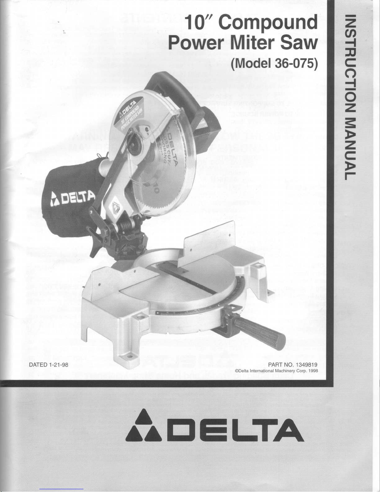
l0"
Compound
Power
Miter
Saw
(Model
36-075)
2
a
{
F
C
o
{
o
z
=
z
c
r
t,'t
PART NO. 1349819
ODelta
International l\,4achinery Corp. 1998
A
AA
trIELTA
Page 2
TABLE OF CONTENTS
SAFETY
RULES.
ADDITIONALSAFETYRULES
FORCOMPOUND
MITERSAWS.
........4
UNPACKING
ASSEMBLYINSTRUCTIONS.
.....5
AssemblingTable
LockHandle
.....5
RotatingTableTogO
Degree
Position
......5
Moving Cuttinghead
To The Up
Position
. . . . 6
Assembling
Dust
Bag
.......6
FASTENING
MACHINETOSUPPORTING
SURFACE
.....6
CONNECTING
SAW
TO POWER SOURCE
PowerConnections.....
-...7
MotorSpecifications...
- ----7
Grounding
Instructions
- - - - -.7
EXTENSTONCORDS
......8
OPERATING
CONTROLS
AND
ADJUSTMENTS
StartingAnd
Stopping
Machine
. -...8
Locking Switch
ln
The "OFF"
Position
. . . . .8
RotatingTableForMiterGutting....
"""9
PointerAndScale
....9
AdjustingPointer
....9
Tilting Cuttinghead
ForBevelCutting
.....10
RearSupporVCarrying
Handle
.....10
Adjusting
Blade Parallel
To Table Slot.
.
. . . 11
Adjusting
Fence 90
Degrees
To Blade
. . . . . 11
Adiusting
DownwardTravel
OlSaw
Blade.
.......11
Adjusting
90And
45 Degree
Bevel Stops
....
- - -.12
AdjustingTension
Of Cuttinghead
Return Spring
'..
-.. -.12
Locking Cuttinghead
lnTheDown
Position
......13
TYPICALOPERATIONSAND
HELPFULHINTS.
........13
AuxiliaryWood
Fence.
. - -. -14
General Cutting
Operations
.......14
CuttingAluminum
...15
Cutting
Bowed Material
....15
Gutting
Crown
Moulding.
...16
MAINTENANCE
ChangingThe
Blade
.
- - - - - -17
Brush InspectionAnd
Replacement.
- '....18
rArtrlELTA
Delta
Building
Trades and
Home Shop
Machinery
Two
Year Limited
Warranty
Delta will repair or
replace, at
its expense and
at its option,
any
Delta machine,
machine
part,
or machine
acces-
sory
which in normai
use has
proven
to be delective
in workmanship
or
material,
provided
that
the
customer
returns the
product prepaid
to a Delta
factory service center
or authorized
service
station
with
proof
of
purchase
ol
the
product
withih two
years
and
provides
Delta
with reasonable
opportunity
to verify
the alleged
defect by
inspeciion.
Delta may
require that electric
motors be
returned
prepaid
to a motor
manufacturer's
authorized
sta-
tion
for inspeclion and
repair or
replacement.
Delta will not be
responsible
for any asserted
defect
which has
resulted
from normal
wear, misuse,
abuse or
repair or alteration
made
or specifically
authorized
by anyone other
than an authorized
Delta Service
facility or
representative. Under
no circumstances
will
Delta be
liable for
inci-
dental or
consequential
damages
resulling from defective
products,
This warranty
is
Delta's sole
warranty and
sets
forth the customer's
exclusive
remedy,
with respect to defective
products;
all other
warranties,
express
or
implied,
whether of
merchantability,
fitness
for
purpose,
or otherwise,
are expressly
disclaimed
by
Delta.
Page 3
SAFETY RULES
Woodworking
can
be dangerous if
safe and
proper
operating
procedures
are not followed.
As with
all
machinery
there
are certain
hazards
invOlved
with the
operation
of
the
product.
Using the machine with
respect and caution will
considerably lessen
the
possi-
bility of
personal
injury. However,
if normal
safety
precautions
are overlooked or ignored,
personal
injury to the
operator may
result.
Safety equipment
such
as
guards, push
sticks, hold-downs,
featherboards,
goggles,
dust
masks
and hearing
protection
can reduce
your
potential
for
injury. But
even the
best
guard
won't
make
up
for
poor
judgment,
carelessness or inattention.
Always
use common
sense
and exercise
caution in the workshop.
lf
a
procedure
feels
dangerous,
don't try
it.
Figure out an
alternative
procedure
that feels
safer. REMEMBER:
Your
personal
safety is
your
responsibility.
This machine
was
designed for
certain applications
only. Delta Machinery
strongly recommends
that this machine
not
be modified
and/oj
yse!
]or
any
application
other than that for
which it
was designed. lf
you
have any
questions
relative
to
a
particular
applica-
tion, DO NOT
use the machine
until
you
have first
contacted
Delta to determine if it
can or should be
performed
on the
product.
DELTA
INTERNATIONAL
MACHINERY
CORP.
MANAGER
OF TECHNICAL
SERVICES
246 ALPHA
DRIVE
PITTSBURGH,
PENNSYLVANIA
1
5238
(lN
CANADA:
644 IMPERIAL
ROAD,
GUELPH, ONTARIO N1H 6M7)
WARNING:
FAILURE
TO
FOLLOW
THESE
RULES
MAY
RESULT
IN
SERIOUS PERSONAL
INJURY
1. FOR
YOUR
OWN SAFETY,
READ INSTRUCTION
MANUAL
BEFORE
OPERATING THE
TOOL.
Learn
the
tool's
application
and limitations
as well
as the
specific
hazards
peculiar
to it.
2. KEEP
GUARDS lN
PLACE
and in working
order.
3, ALWAYS
WEAR EYE PROTECTION.
4.
GROUND ALL
TOOLS.
lf tool is
equipped
with three-
prong plug,
it
should
be
plugged
into
a three-hole
electrical
receptacle.
lf
an adapter is
used to
accommodate
a two-
prong
receptacle,
the
adapter lug
must
be attached
to a
known
ground.
Never
remove
the third
prong.
5. REMOVE
ADJUSTING
KEYS
AND WRENCHES,
Form
habit
of checking to
see that keys
and
adjusting wrenches
are
removed
from
tool
before turning it
"on."
6. KEEP WORK
AREA
CLEAN.
Cluttered
areas
and
benches invite
accidents.
7.
DON'T
USE ILLDANGEROUS
ENVIRONMENT.
Don't
use
power
tools
in
damp or wet locations,
or expose
them
to rain.
Keep work
area well-lighted.
8. KEEP
CHILDREN
AND VISITORS
AWAY.
Att
chitdren
and visitors
should
be kept
a safe distance from
work
area.
9.
MAKE
WORKSHOP
CHILDPROOF
-
with
padtocks,
master
switches,
or
by
removing
starter keys.
10.
DON'T FORCE
TOOL.
lt will
do the
job
better and
be
safer
at the rate for
which it
was
designed.
11.
USE RIGHT
TOOL. Don't
force
tool or attachment
to
do
a
job
for which
it was
not designed.
12.
WEAR PROPER
APPAREL.
No
loose clothing,
gtoves,
neckties,
rings,
bracelets,
or other
jewelry
to
get
caught
in
moving
parts.
Nonslip
footwear.
is recommended.
Wear
protective
hair
covering to
contain long
hair.
13.
ALWAYS
USE
SAFETY
GLASSES. Wear
safety
gtasses.
Everyday
eyeglasses
only have
impact
resistant
lenses;
they are not
safety
glasses.
Also
use face
or
dust mask if
cutting
operation
is dusty.
14.
SECURE WORK.
Use
clamps or a vise
to hotd
work
when
practical.
lt's
safer than
ubing
your
hand
and frees
both hands
to operate
tool.
15.
DON'T
OVERREACH. Keep
proper
footing
and balance
at
all
times.
16.
MAINTAIN TOOLS
lN TOP
CONDITION.
Keep
toots
sharp and clean for
best and safest
performance.
Follow
instructions
for lubricating
and changing
accessories.
17. DISCONNECTTOOLS
before
servicing
and when
changing
accessories such as
blades, bits,
cutters,
etc.
18.
USERECOMMENDEDACCESSORIES.
The
use of
accessories
and attachments not
recommended
by
Delta
may
cause hazards or risk
of injury to
persons.
19. REDUCE
THE RISK
OF UNINTENTIONAL
START.
lNG,
Make
sure switch is in
"OFF"
position
before
plugging
in
power
cord.
20.
NEVER
STAND ON TOOL.
Serious injury
could
occur
if the tool is tipped
or if the
cutting tool is
accidentally
contacted.
21,
CHECK DAMAGED
PARTS. Before
further
use
of
the
tool,
a
guard
or other
part
that
is damaged
should
be care-
fully
checked to ensure that it
will operate
properly
and
perform
its
intended function
-
check for
alignment
of moving
parts,
binding of
moving
parts,
breakage
of
parts,
mounting,
and any other
conditions that may
affect its
operation.
A
guard
or other
part
that is
damaged
should be
properly
repaired
or replaced.
22. DIRECTION
OF FEED. Feed
work into
a blade
or cutter
against the
direction of rotation
of the
blade or cutter
only.
23. NEVER LEAVETOOL
RUNNING
UNATTENDED. TURN
POWER
OFF.
Don't leave
tool
until
it
comes to
a complete
stop.
24.
DRUGS, ALCOHOL,
MEDICATION.
Do
not operate
tool while
under the influence
of drugs,
alcohol
or
any
medication.
25. MAKE
SURE TOOL IS DISCONNECTED
FROM
POWER
SUPPLY while motor is
being mounted,
connected or re-
connected.
26. WARNING: The
dust
generated
by certain woods
and
wood
products
can be injurious to
your
health.
Always
oper-
ate machinery in
well ventilated
areas
and
provide
for
proper
dust
removal.
Use wood
dust collection
svstems
whenever
possible.
Page 4
ADDITIONAL
SAFETY
RULES
FOR
COMPOUND
MITER
SAWS
1. WARNING:
USE
ONLY
CROSS-CUTTING
SAW
BLADES.
WHEN USING
CARBIDE
TIPPED
BLADES,
MAKE SURE
THEY
HAVE
A NEGATIVE
HOOK
ANGLE.
DO NOT USE
BLADES
WITH DEEP GULLETS
AS
THEY CAN
DEFLECT
AND CONTACT
GUARD.
2.
WARNING:
Do not operate
the
miter saw
until
it is
completely
assembled
and
installed according
to the
instructions.
3.
lF
YOU ARE
NOT thoroughly
familiar
with the oper-
ation of
compound
miter saws, obtain
advice
from
your
supervisor,
instructor or
other
qualified person.
4. DO
NOT
pedorm
any operation
freehand.
Secure or
clamp
workpiece
firmly against
fence.
5.
WARNING:
Keep
hands out
of
path
of
saw blade.
lf
the
workpiece
you
are cutting
would cause
your
hand to
be
within
4 inches of
the saw
blade,
the
workpiece
should
be clamped
in
place
before
making
cut.
6.
BE SURE
blade
is sharp,
runs
freely and
is free of
vibration.
7. ALLOW
the
motor to come
up to
full speed
before
starting
cut.
B.
KEEP
motor air slots
clean
and
free of chips.
L
ALWAYS
MAKE SURE
all clamp
handles are
tight
before
cutting,
even
if the table
is
positioned
in one
of the
positive
stops.
10.
BE
SURE
blade
and
flanges
are clean
and
that
arbor
screw
is tightened
securely.
11 . USE
only
blade
flanges specif
ied
for
your
saw.
12.
NEVER use
blades
larger or
smaller
in diameter
than
ten
inches.
13.
NEVER
apply
lubricants
to the blade
when it
is
runnrng.
14. ALWAYS
check
the blade
for cracks
or damage
before
operation.
Replace
cracked or
damaged
blade
immediately.
15.
NEVER use
blades
recommended
for operation
at
less than
6000
RPM.
16.
DO NOT
operate
the saw
without
guards
in
place.
17. ALWAYS
keep
the
lower blade
guard
in
place
and
operating
properly.
18.
NEVER
reach around
or behind
saw
blade.
19.
MAKESURE
blade
is
not contacting
workpiece
before
switch
is turned
on.
20. NEVER
lock the
switch
in the
"ON"
position.
21. IMPORTANT
After completing
cut,
release
power
switch
and
wait for coasting
blade
to stop
before
return-
ing saw
to
raised
Position.
22.
TURN OFF
tool and
wait
for saw
blade
to stop
before
moving
workpiece
or
changing
settings.
23. DO
NOT
remove
jammed
or
cut-off
pieces
until blade
has stopped.
24.
NEVER
cut
ferrous
metals
or
masonry'
25.
NEVER
recut small
Pieces.
26.
PROVIDE
adequate
support
to
the sides
of
the saw
table
for
long
workPieces.
27. NEVER
use
the
miter
saw
in an area
with flammable
liquids or
gases.
28.
NEVER
use solvents
to clean
plastic pafts.
Solvents
could
possibly
dissolve
or othenruise
damage
the
material.
Only
a soft
damp
cloth
should
be
used
to clean
plastic
pans.
29. DISCONNECT
power
before
changing
blades
or
servicing.
30.
DISCONNECT
saw
from
power
source
and clean
the machine
before
leaving
it.
31.
MAKE
SURE
the
work area
is cleaned
before
leav-
ing the
machine.
32.
THE
USE
of attachments
and
accessories
not
rec-
ommended
by
Delta
may
result
in the
risk of
injuries.
33.
SHOULD
any
part
of
your
miter saw
be
missing,
damaged
or
fail
in any
way, or
any electrical
component
fail
to
per{orm
properly,
shut
off switch
and
remove
plug
from
power
supply
outlet.
Replace
missing,
damaged
or
failed
parts
before
resuming
operation.
34.
ADDITIONAL
INFORMATION
regarding
the safe
and
proper
operation
of
this
product
is available
from the
National
Safety
Council,
1121 Spring
Lake
Drive,
ltasca,
lL60143-3201,
in the
Accident
Prevention
Manual
for
Industrial
Operation
and also
in the Safety
Data Sheets
provided
by
the
NSC.
Please
also
refer
to the
American
National
Standard
Institute
ANSI
01.1 Safety
Require-
ments
for
Woodworking
Machinery
and
the U.S.
Depart-
ment of
Labor
OSHA
1910.213
Regulations.
35.
SAVE
THESE
INSTRUCTIONS.
Refer
to them often
and
use
them
to
instruct others.
Page 5
UNPAGKING
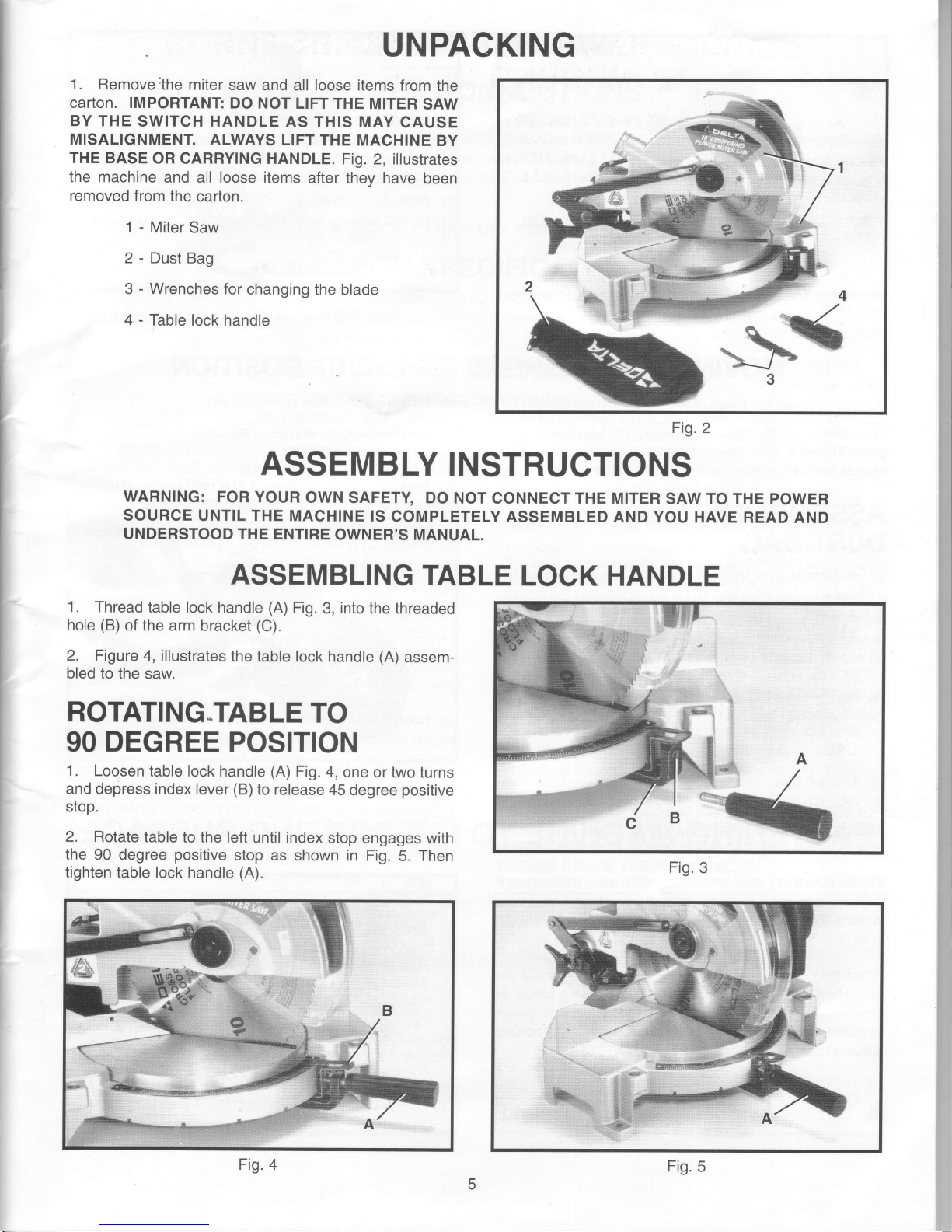
1.
Remove;the miter
saw
and all loose items
lrom the
carton. IMPORTANT
DO
NOT LIFT THE
MITER
SAW
BY THE
SWITCH HANDLE
AS THIS
MAY
CAUSE
MISALIGNMENT.
ALWAYS LIFT
THE MACHINE
BY
THE BASE
OR CARRYING HANDLE.
Fig. 2, illustrates
the machine
and all loose items
after they have
been
removed
from the
cafton.
1 - Miter
Saw
2 - Dust Bag
3
-
Wrenches
for
changing
the blade
4
-
Table lock handle
1. Thread
table lock
handle
(A)
Fig.
3,
into
the threaded
hole
(B)
of the
arm bracket
(C).
2. Figure
4, illustrates
the
table lock handle
(A)
assem-
bled to
the saw.
ROTATING.TABLE
TO
90
DEGREE
POSITION
1, Loosen
table lock
handle
(A)
Fig.
4,
one or two turns
and
depr,ess index lever
(B)
to release
45
degree
positive
stop.
2. Rotate
table
to the left
until index
stop engages with
the 90
degree
positive
stop as
shown in Fig.
5. Then
tighten table
lock handle
(A).
4
Fig. 2
ASSEMBLY
INSTRUCTIONS
WARNING: FOR
YOUR
OWN
SAFETY DO
NOT
CONNECT
THE
MITER
SAW
TO
THE POWER
SOURCE
UNTIL THE MACHINE
IS
COMPLETELY
ASSEMBLED AND
YOU HAVE
READ AND
UNDERSTOOD
THE ENTIRE
OWNER'S MANUAL.
ASSEMBLING
TABLE
LOCK
HANDLE
Fig.
3
Fig.
4
Fig.
5
Page 6
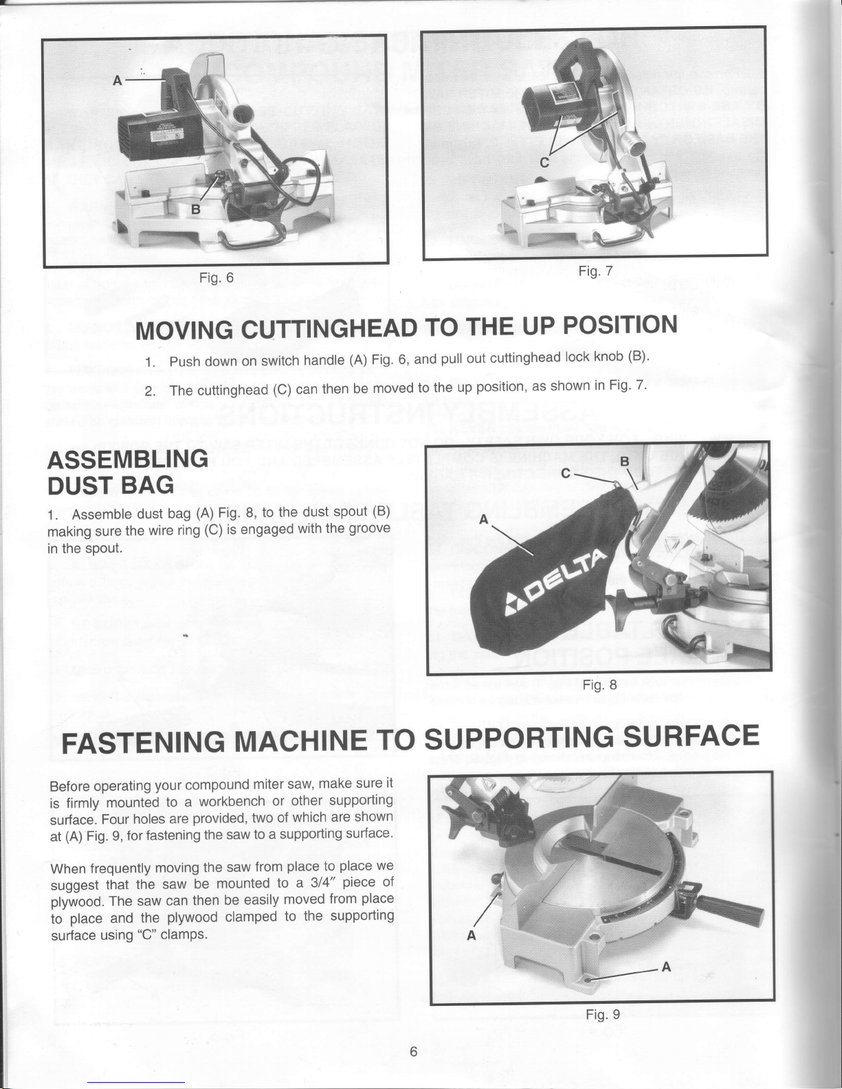
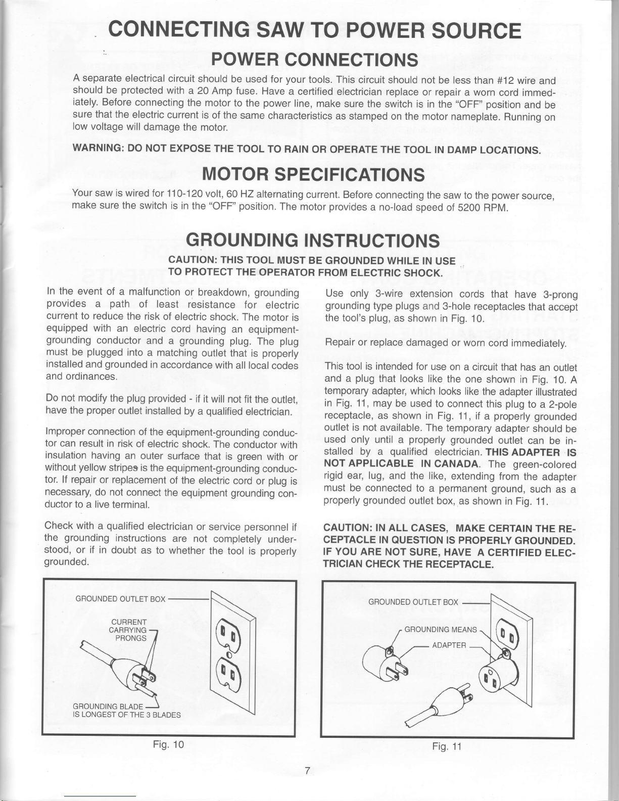
Fig. 6
Fig.7
MOVING
CUTTINGHEAD
TO
THE
UP
POSITION
Push
down
on
switch
handle
(A)
Fig.
6, and
pull
out
cuttinghead
lock
knob
(B)'
The
cuttinghead
(c)
can
then
be
moved
to
the
up
position,
as
shown
in Fig.
7.
1.
2.
ASSEMBLING
DUST
BAG
1.
Assemble
dust
bag
(A)
Fig.
8, to
the
dust
spout
(B)
making
sure
the
wire
ring
(C)
is engaged
with
the
groove
in the
spout.
FASTENING
MACHINE
TO SUPPORTING
SURFACE
Before
operating
your
compound
miter
saw,
make
sure
it
is
firmly
mounted
to
a
workbench
or
other
suppofiing
surface.
Four
holes
are
provided,
two
of
which
are
shown
at
(A)
Fig. 9,
for
fastening
the saw
to
a supporting
sudace.
When
frequently
moving
the
saw
from
place
to
place
we
suggest
that
the
saw
be
mounted
lo
a 314"
piece
of
plywood. The saw
can
then
be easily
moved
from
place
to
place
and
the
plywood clamped
to
the
supporting
surface
using
"C"
clamPs.
Fig. 8
Fig. 9
Page 7
CONNECTING
SAW TO
POWER
SOURCE
POWER
CONNECTIONS
A
separate
electrical
circuit
should
be used
for
your
tools. This
circuit
should not
be less than
#12 wire
and
should
be
protected
with
a 20
Amp fuse.
Have
a
cerlified electrician
replace
or repair
a worn
cord immed-
iately.
Before
connecting
the motor
to
the
power
line,
make sure
the switch is in
the
"OFF" position
and be
sure
that the
electric
current
is
of
the
same
characteristics
as stamped
on the motor
nameplate.
Running
on
low
voltage
will
damage
the motor.
WARNING:
DO NOT
EXPOSE
THE
TOOL
TO RAIN
OR OPERATE THE
TOOL IN
DAMP
LocATIoNs.
MOTOR
SPECIFICATIONS
Your
saw is
wired for
110-120
volt,
60 HZ
alternating
current. Before
connecting
the
saw to the
power
source,
make
sure the
switch
is in
the
"OFF" position.
The
motor
provides
a
no-load
speed of
52OO RPM.
GROUNDING
INSTRUCTIONS
CAUTION:
THIS
TOOL
MUST
BE
GROUNDED WHTLE
tN
USE
.
TO PROTECT
THE
OPERATOR
FROM
ELECTRIC
SHOCK.
In
the
event of
a malfunction
or
breakdown,
grounding
provides
a
path
of least
resistance
for
electric
current
to reduce
the
risk
of electric
shock.
The
motor is
equipped
with
an
electric
cord having
an equipment-
grounding
conductor
and a
grounding
plug.
The
plug
must
be
plugged
into
a matching
outlet that
is
properly
installed
and
grounded
in
accordance
with
all localcodes
and
ordinances.
Do not
modify
the
plug provided
-
if it wiil
not fit
the
ouilet,
have
the
proper
outlet installed
by
a
qualified
electrician.
lmproper
connection
of the
equipment-grounding
conduc-
tor
can result
in risk
of electric
shock. The
conductor
with
insulation
having
an
outer surface
that
is
green
with
or
without
yellow
stripes is
the
equipment-grounding
conduc-
tor.
lf repair
or replacement
of the
electric
cord or
plug
is
necessary
do not
connect
the
equipment
grounding
con-
ductor to
a live terminal.
Check with
a
qualified
electrician
or
service
personnel
if
the
grounding
instructions
are not
completely
under-
stood,
or if in
doubt
as
to whether
the
tool is
properly
grounded.
GROUNDED
OUTLET
BOX
IS LONGEST
OF THE
3 BLADES
Use only
3-wire extension
cords
that have
3-prong
grounding
type
plugs
and
3-hole receptacles
that
accept
the tool's
plug,
as
shown in Fig.
10.
Repair
or replace
damaged
or worn
cord immediately.
This
tool is intended
for
use
on a circuit
that has
an
ouflet
and
a
plug
that looks
like
the
one shown in
Fig.
10. A
temporary
adapter, which
looks
like
the
adapter illustrated
in
Fig. 11,
may
be used to
connect
this
plug
to a 2-pole
receptacle,
as
shown in Fig.
11, if
a
properly
grounded
outlet is not
available. The
temporary
adapter
should
be
used
only until
a
properly
grounded
outlet can
be in-
stalled by
a
qualified
electrician.
TH|S
ADAPTER
lS
NOT
APPLICABLE
lN
CANADA. The
green-cotored
rigid
ear, lug,
and the like,
extending
from
the
adapter
must
be connected
to
a
permanent
ground,
such
as a
properly
grounded
outlet
box,,as
shown in
Fig. 11,
CAUTION:
lN ALL
CASES,
MAKE
CERTATN
THE
RE-
CEPTACLE IN
QUESTION IS PROPERLY
GROUNDED.
IF YOU ARE
NOT
SURE, HAVE
A
CERTIFIED
ELEC.
TRICIAN
CHECK THE
RECEPTACLE.
GBOUNDED
OUTLET BOX
GROUNDING
MEANS
ADAPTER
11
Fig.
10
Fig.
Page 8

Use
proper
extension
cords.
Make sure
your
extension
cord
is in
good
condition
and
is a 3-wire
extension
cord
which has a 3-prong
grounding
type
plug
and a 3-pole
receptacle
which
will accept
the tool's
plug.
When using
an
extension
cord,
be sure
to use one
heavy enough
to
carry
the current
of the
saw.
An
undersized
cord
will
cause a drop
in line voltage,
resulting
in loss of
power
and overheating.
Fig. 12, shows
the correct
gage
to use
depending
on
the cord
length.
lf in
doubt,
use
the next
heavier
gage.
The smaller
the
gage
number,
the
heavier
the cord.
TOTAL
LENGTH OF
GAGE
OF
EXTENSION
CORD
IN FEET
CORD
TO USE
0-25
14AWG
26 - 50
12 AWG
Over
50
Not
Recommended
Fig.
12
13
Fig.
EXTENSION
CORDS
OPERATING
CONTROLS
AND
ADJUSTMENTS
STARTING
AND
STOPPING
MACHINE
To start
the machine,
depress switch
trigger
(A)
Fig.
13.
To
stop
the
machine,
release the switch
trigger.
This miter saw
is equipped
with an automatic
electric
blade brake.
As soon
as the switch
trigger
(A)
Fig.
13, is
released,
the electric
brake
is activated and
stops
the
blade
in seconds.
DANGER:
A
TURNING SAW
BLADE CAN
BE
DANGER.
OUS.
AFTER
COMPLETING
CUT,
RELEASE
SWITCH
TRTGGER
(A)
FlG. 13,
TO ACTIVATE
BLADE
BRAKE.
KEEP CUTTINGHEAD
DOWN UNTIL
BLADE
HAS
COME
TO A COMPLETE
STOP.
WARNING:
THE TORQUE
DEVELOPED
DURING
BRAKING
MAY LOOSEN
THE
ARBOR SCREW.
THE
ARBOR
SCREW
SHOULD
BE CHECKED
PERIOD.
ICALLY
AND TIGHTENED
IF NECESSARY.
LOCKING
SWITCH
IN
THE
"OFF''
POSITION
IMPORTANT
We suggest
that
when the
miter saw
is not
in use,
the switch be
locked
in the
"OFF"
position
using
a
padlock (B),
as shown
in
Fig. 14.
Fig.
14
Page 9

16Fig.
15Fig.
ROTATING
TABLE
FOR MITER
CUTTING
Your miter
saw will
cut any angle from
a straight
90 degree cullo 47 degrees right
and
left.
Simply loosen
lock handle
(A)
Fig. 15,
one ortwo turns,
depress index lever
(B)
and
move
the
control arm to
the desired
angle. THEN TIGHTEN LOCK
HANDLE
(A).
The
miter
saw is equipped
with
positive
stops
at
the
0,22-112, and 45 degree right
and
left
positions.
Simply loosen lock
handle
(A)
Fig. 15,
and
move
the control arm
untilthe
bottom
of the index lever
(B)
engages into
one of the
positive
stops, four
of
which
are
shown at
(C).
THEN
TIGHTEN
LOCK HANDLE
(A).
To
disengage the
positive
stop,
depress index lever
(B).
In
addition,
a triangle indicator
(D)
Fig. 16,
is
provided
on the
miter
scale at the
31-5/8
right
and left miter
positions
for
cutting
crown moulding. Refer
to the "CUTTING
CROWN MOULDING"
section of this manual,
IMPORTANT
ALWAYS
TIGHTEN
LOCK HANDLE
(A)
Ftc. 16, BEFORE
CUTT|NG.
POINTER
AND
SCALE
A
pointer
(E)
Fig.
17, is
supplied
which indicates
the
actual angle
of cut. Each line
on the
scale
(F)
represents
112
degree.In effect,
when the
pointer
is moved
from
one
line to
the next
on the scale,
the angle
of cut is changed
by 112 degree.
ADJUSTING
POINTER
lf it
becomes
necessary
to
adjust the
pointer
(E)
Fig.
17,
simply loosen
screw
(G),
adjust
the
pointer
accordingly
and tighten
screw
(G).
Fig.17
Page 10

1BFig.
TILTING
CUTTINGHEAD
FOR
BEVEL CUTTING
The cuttinghead of
your
compound
miter
saw
can be tilted to cut
any bevel
angle
from
a 90
degree straight
cut off to a
45
degree
left bevel angle by
loosening bevel
lock handle
(A)
Fig. 18, tilting cutting
arm
(B)
to the
desired angle
and tightening
lock handle
(A).
Positive stops are
provided
to rapidly
position
the
saw
blade at 90
and
45
degrees
to the
table. Refer
to the
section of
this manual titled
"ADJUSTING 90
AND 45 DEGREE
BEVEL STOPS."
The bevel angle
of the
cutting arm
is determined by
the
position
of the
pointer (C)
Fig,
18,
on
the scale
(D),
In
addition,
a triangle
indicator is
provided
on the bevel scale
at
the
33-718
degree
bevel angle
for cutting
crown
moulding.
Refer to the "CUTTING CROWN
MOULDING"
section of
this manual.
REAR
SUPPORT/CARRYING
HANDLE
A rear support bar
(A)
Fig.
19, is
provided
to
prevent
the
miter saw
from tipping
to the rear
when the cutting-
head is
returned to the up
position
after
a cut has been
made. For
maximum support
the bar
(A)
should be
pulled
out as
far
as
possible.
The
support
bar
(A)
also acts as
a carrying
handle,
as shown
in Fig. 20,
when transporting
the saw.
Fig.
19
Fig. 20
10
Page 11

ADJUSTING BLADE
PARALLEL TO TABLE
SLOT
1. DISCONNECT
THE SAW FROM THE POWER
SOURCE.
2.
NOTE: This adjustment
should be checked with the
cutting arm
moved
all the way to the right
(blade
90
degrees to the table)
and the table in the 90 degree
straight
cut-off
position
(blade
90 degrees to the fence).
3.
Lower
the cutting arm. The
saw blade
(A)
Fig. 21,
should
be
parallel
to the
left
edge
(B)
of
the table
opening.
4. lf an
adjustment
is necessary,
loosen three
screws
(C)
Fig. 21, and move the
cutting arm until the blade is
parallel
with
the
left
edge
(B)
of the table
opening. Then
tighten the three screws
(C).
ADJUSTING
FENCE
90
DEGREES
TO BLADE
lf the fence
(A)
Fig.
22, is ever removed from
the saw it
should be adjusted
so
it is
90 degrees to the
blade
when
it is replaced,
as
follows:
1.
DISCONNECT THE
SAW
FROM
THE POWER
SOURCE.
2. This
adjustment should be made
only after the blade
has
been adjusted
parallelto
table opening,
as
previous-
ly explained.
3. Using a square
(B)
Fig. 22,
place
one end of the
square against the fence
(A)
and the other
end against
the
slot
in the
table as shown.
4.
lf an adjustment is necessary,
loosen the two
screws
(C)
Fig. 23,
and adjust fence
90 degrees to the table
opening. Then
tighten the two
screws
(C).
ADJUSTING
DOWNWARD
TRAVEL
OF SAW
BLADE
1.
DISCONNECT THE
SAW FROM THE POWER
SOURCE.
2. The
downward travel of the
saw blade can be limited
to
prevent
the saw blade from
contacting any metal
surfaces of the machine. This
adjustment is made
by
loosening locknut
(A)
Fig. 24, and turning
adjusting screw
(B)
in
or out.
3.
When making
this adjustment,
MAKE SURE THE
MACHINE
IS DISCONNECTED
FROM THE POWER
SOURCE
and
lower
the blade as far
as
possible.
Rotate
the
blade by
hand
to make certain the
teeth do not con-
tact
any
metal
surfaces
and adjust
if
necessary.
4. After
the downward travel
of the saw blade has
been
adjusted, tighten
locknut
(A)
Fig.21
Fig.22
Fig. 23
Fig.24
Page 12

rr
I
ADJUSTING
90
AND
45
DEGREE
BEVEL
STOPS
1.
DISCONNECT
THE
SAW
FROM
THE
POWER
SOURCE.
2.
Loosen
bevel
lock
handle
and
move
the
cutting
arm
allthe
way
to the
right,
then
tighten
the
bevel
lock handle'
3.
Using
a square
(A)
Fig.
25,
place
one
end
of
the
square
on
the
table
and
the
other
end
against
the blade'
Check
to see
if the blade
is at
90
degrees
to the
table,
as
shown
in
Fig.
25.
4.
lf an
adjustment
is
necessary,
loosen
locknut
(B)
Fig.
26,
and
turn
screw
(C)
until
head
of screw
(C)
con-
tacts
casting
(D)
when
blade
is
90
degrees
to the
table'
Then
tighten
locknut
(B).
5.
Loosen
bevel
lock
handle
and
move
the
cutting
arm
all
the
way to
the
left bevel
position
and
tighten
bevel
lock
handle.
6.
Using
a combination
square
(A)
Fig.
27, check
to see
if the
blade
is at
45 degrees
to the
table,
as
shown.
7.
lf an
adjustment
is necessary,
loosen
locknut
(E)
Fig.
28, and
turn
screw
(F)
until
screw
(F)
contacts
casting
(G)
when
blade
is 45 degrees
to
the
table.
Then
tighten
locknut
(E).
8.
These
positive
stops
enable
you
to
rapidly
position
the blade
at
the 90
and
45 degree
bevel
angle
to
the
table.
ADJUSTING
TENSION
OF
CUTTINGHEAD
RETURN
SPRING
The
tension
of
the cuttinghead
return
spring
has been
adjusted
at
the
factory
so
the
cuttinghead
returns
to the
up
position
after
a cut
has
been
made.
lf it ever
becomes
nec-
essary
to
re-adjust
the spring
tension,
proceed
as
follows:
1.
Loosen
locknut
(A)
Fig.
28A,
and
turn
screw
(B)
clockwise
to
increase
or counterclockwise
to decrease
the
spring
tension.
After
the
spring
tension
has been
adjusted,
tighten
locknut
(A).
Fig.2BA
Fig.
25
Fig,
26
Fig.27
Fig.
28
12
Page 13

LOCKING
CUTTINGHEAD
IN THE
DOWN
POSITION
When
transporting
the
saw, the
cuttinghead
should always
be locked in
the down
position.
This
can be
accomplished
by lowering
the
cutting arm
(A)
Fig. 29,
and
pushing
in
plunger
(B)
until
other end
of
plunger
(B)
engages
with
hole
in cutting
arm. IMPORTANT
NEVER
CARRY THE
COMPOUND
MITER
SAW
BY
THE
SWITCH HANDLE.
THIS MAY
CAUSE MISALIGNMENT.
ALWAYS
LIFT
THE
MACHINE
BY THE
BASE.
29Fig.
TYPICAL
OPERATIONS
AND HELPFUL
HINTS
1. Before
cutting,
make
certain the
cutting
arm and table
are at their correct
settings
and
firmly
locked
in
place.
2.
Before
cutting,
determine
that the workpiece
is
the
right
size for the
saw,
3. Place
the workpiece
on the table
and hold
or clamp it firmly
against the fence.
Fig.
30,
illustrates
the
accessory
36-221work
clamp
(A)
being used to clamp a workpiece
to the fence.
The
clamp
(A)
can also
be used on the right
side of the machine.
4.
For
best
results,
cut at
a slow, even
cutting rate.
5. WARNING:
lf the
workpiece
you
are cutting would
cause
your
hand
to be within 4
inches
of
the
saw blade, the
workpiece
should
be clamped
in
place
before
making
cut.
See
Fig.
30.
6. Never
attempt
any freehand
cutting
(wood
that is not held firmly
against the fence
and
table).
Fig.
30
13
Page 14

AUXILIARY
WOOD
FENCE
When
performihg
multiple
or
repetitive
cut-off
operations
that
result
in small
cut-off
pieces,
one
inch or
less,
it
is
possible
for the
saw blade
to catch
the
cut-off
pieces
and
project
them
out
of the
machine
or
into the
blade
guard
and
housing,
possibly
causing
damage
or
injury.
In order
to
limit
the
possibility
of
personal injury
or blade
guard
damage,
an
auxiliary
wood
fence can
be
mounted
to
your
saw
as
follows:
Holes
are
provided
in
the
fence
to attach
an
auxiliary
fence
(A)
Fig. 31.
This
auxiliary
fence
is constructed
of
straight
wood
approximately
112
inch thick
by
3
inches
high by
20 inches
long.
NOTE:
The auxiliary
fence
(A)
is
used
ONLY
with the
saw
blade
in the 0
degree
bevel
position
(90
degrees
to the
table).
When bevel
cutting
(blade
tilted)
the auxiliary
fence
will have
to be
removed.
GENERAL
CUTTING
OPERATIONS
1. Your
compound
miter saw
has the
capacity
to cut
standard
2 x 6's
at
the
straight
90
degree
cut-off
position,
as
shown
in Fig. 32,
or
at the
45 degree
bevel
position,
as
shown
in Fig. 33.
2. Cutting
a standard
4
x 4 is easily
accomplished
with
your
compound
miter saw,
as
shown
in Fig. 34.
Fig. 31
Fig. 32
Fig.
33
Fig. 34
Page 15

CUTTING
ALUMINUM
Aluminum extrusions
such as
used for
making aluminum
screens
and storm
windows can easily
be cut
with
your
compound
miter saw.
When cutting aluminum
extrusions,
or other sections
that can be cut
with a saw blade and
are
within the capacity
of the
machine,
position
the material
so
the blade
is
cutting
through
the smallest cross-
section, as shown
in
Fig.
35.
The wrong
way to cut
aluminum
angles
is illustrated in
Fig.
36.
Be sure to apply
a stick
wax
(similar
to
Johnson's
stick
wax #140) to the
blade
before cutting any
aluminum stock.
This stick
wax
is available at
most industrial
mill supply
houses. The
stick
wax
provides proper
lubrication and
keeps chips
from
adhering
to the blade.
NEVER
APPLY LUBRICANT
TO
THE BLADE WHILE
THE MACHINE IS
RUNNING.
t=*"=*
RIGHT
FENCE
+
WRONG
Fig. 36
35
Fig.
CUTTING
BOWED
MATERIAL
When cutting
flat
pieces,
first check
to
see
if the material
is bowed.
lf it is, make sure
the material is
positioned
on
the table as shown
in Fig. 37.
lf the
material is
positioned
the
wrong way, as shown
in Fig. 38,
the workpiece
will
pinch
the blade
near the completion
of the cut.
RIGHT
Fig. 37
WRONG
38Fig.
tc
Page 16

'll
til
lt
CUTTING
CROWN
MOULDING
One
of
the
many
features
of
your
saw
is the
ease
of
cutting
crown
moulding.The
following
is
an
example
of
cutting
both
inside
and
outside
corners
on 53/38
degree
wallangle
crown
moulding.
NOTE:
When
cutting
45 degree
wall
angle
crown
moulding,
the
following
procedure for
inside
and
outside
corners
is the
same
with the
exception
that
the
bevel
position
will always
be
at 30
degrees
and
the
miter
position
will
be 35-114
degrees
to the
right or
left.
1
. Move
the table
to the
31-5/B
degree
right
miter
posi-
tion
and
lock
the
table
in
position.
NOTE:
A triangle
indi-
cator
is
provided on
the
miter
scale
to
find
this
angle
quickly.
2.
Tilt
the
saw
blade
to the
33-718
degree
left
bevel
position
and
tighten
bevel
lock
handle.
NOTE:
A triangle
indicator
is
provided
on
the
bevel
scale
to
find
this angle
quickly.
3.
Place
the
crown
moulding
on
the
table
with
the
CEILING
EDGE
of
the
moulding
against
the
fence,
and
make
the cut,
as
shown
in
Fig. 39.
NOTE:
The
piece
of
crown
moulding
used
for
the outside
corner
will always
be
on
the
right
hand
side
of
the
blade,
as
shown
at
(A)
Fig.
39.
The
piece
of
crown
moulding
used
for the
inside
corner
will
always
be on
the
left
hand side
of
the blade,
as
shown
at
(B)
Fig. 39.
4.
To
make
the
matching
halves
of
the
inside
and
out-
side
corners,
simply
rotate
the
table
to the
31-5/B
degree
left
miter
position
and
tighten
table
lock
handle.
NOTE:
A
triangle
indicator
is
provided
on
the
miter
scale to
find
this
angle
quicklY.
5.
Place
the crown
moulding
on
the
table
with
the
WALL
EDGE
of
the crown
moulding
against
the
fence
and
make
the
cut.
Again,
the
piece
of
crown
moulding
used
for
the outside
corner
will
always
be on
the
right
side
of
the
blade,
as
shown
at
(C)
Fig.
40.
The
piece
of
crown
moulding
used
for the
inside
corner
will
always
be
on
the
left
side
of
the
blade,
as
shown
at
(D)
Fig.
40.
6.
Fig.
41,
illustrates
the
two
outside
corner
pieces;
(A)
being
the
piece
cut
at
(A)
Fig.
39,
and
(C)
being
the
piece
cut
at
(C)
Fig.
40.
7.
Fig.42,
illustrates
the
two
inside
corner
pieces;
(B)
being
the
piece
cut
at
(B)
Fig. 39,
and
(D)
being
the
piece
cut
at
(D)
Fig.
40.
Fig.
39
Fig.
40
Fig.
41
Fig.42
Page 17

MAINTENANCE
CHANGING
THE BLADE
WARNING: USE ONLY CROSS-CUTTING
SAW
BLADES.
WHEN
USING
CARBIDE
TIPPED BLADES,
MAKE
SURE
THEY
HAVE A NEGATIVE
HOOK
ANGLE. DO
NOT
USE
BLADES WITH
DEEP
GULLETS
AS THEY
CAN
DEFLECT
AND
CONTACT
THE
GUARD.
USE ONLY
10"
DIAMETER
SAW
BLADES
WHICH ARE
RATED
FOR
6000
RPM OR HIGHER
AND HAVE
5/8"
DIAMETER ARBOR
HOLES.
1. DISCONNECT
THE MACHINE
FROM THE
POWER
SOURCE.
2.
Loosen
screw
(A)
Fig.
43,
and
rotate cover
(B)
to the
rear as shown
in Fig. 44.
3.
To remove the saw blade,
insert hex
wrench
(C)
Fig.
45, into the hex hole located on the
rear
end of
the
arbor
shaft, to
keep
the shaft
from turning.
4. Using wrench
(D)
Fig. 46, loosen arbor screw
(E)
by
turning it clockwise.
5. Remove arbor screw
(E)
Fig. 46, outside blade
flange
(F)
and saw blade
(G)
from
saw arbor.
6.
Assemble new saw blade
MAKING
CERTAIN
TEETH
OF SAW
BLADE ARE
POINTING DOWN AT THE
FRONT and
reassemble outside blade
flange
(F)
Fig. a6,
and arbor screw
(E)
by turning it counterclockwise using
wrench
(D)
Fig.
46. At
the same
time
use
hex wrench
(C)
Fig. 45, to keep the arbor
from
turning.
7. Reolace cover that
was rotated to the rear in STEP 2.
8. WARNING:
REMOVE WRENCHES
(C)
FIG. 45, AND
(D)
FrG.46, BEFORE
TURNTNG
ON
THE POWER.
Fig. 43
Fig. 45
17
Page 18

BRUSH
INSPECTION
AND
REPLACEMENT
CAUTION:
BEFORE
INSPECTING
THE
BRUSHES'
DISCONNECT
THE
MACHINE
FROM
THE
POWER
SOURCE.
Brush
life varies.
lt depends
on
the
load
on
the
motor.
Check
the brushes
after
the
first
50
hours
of use
for a
new
machine
or after
a
new
set
of brushes
has been
installed.
After the
first
check,
examine
them
after
about
1O
hours
of use
until
such
time
that
replacement
is nec-
essary.
To
inspect
the brushes,
proceed
as
follows:
1.
Remove
three
screws
(A)
Fig.
47, and
remove
motor
cover
(B).
2.
The brushes
are
located
in the
two
holders
(C)
Fig.
aB.
Remove
spade
type
terminal
connector
(D)
and
pull
out
brush
holders
(C).
3.
Fig.
49,
illustrates
one
of
the brushes
(E)
removed
from
the
holder
(C).
When
the carbon
on either
brush
(E)
is
worn
to 3116"
in length
or
if either
spring
(F)
or
shunt
wire
is burned
or
damaged
in any
way,
replace
both
brushes.
lf the
brushes
are
found
serviceable
after
re-
moving,
reinstallthern
in
the same
position
as
removed'
Fig.47
Fig.
48
Fig.
49
Page 19

r-r l-l E t
rrr
a
36-075
h-r r
MB4D
--ts-E
^ r"",",,"".*";
I A
tO"
COfUlpOUtto
pOWen
rulfen
SnW
Pi]*?ollirersrll
o
/
\zl-\
\o
\.o
#{
u"/-
AVAILABLE
AS AN
ACCESSORY
18-r
\
)N-,/
^\
I
r'
ooX-
,''
-./.
"
/_
37
(3)
"'
u"z''-sa
(s)
4E
49
50
S7E?,,,
L..-az
(z)
(3)
tnr
,ol\
\
ry
21
22
ZJ
gr/
//
42\
V .,-3s
>
\al
a/r4o
(2)
AA
-LJ
/
.r''
-"
.r''
.l'
41
(2)
45
46
A1
4
(4)
s
(4)
6
(4)
63-\
|
\rll
v
84:
I
\l
83\
R?-81\
----'t-7g
79
()\
(2)
(t\
Page 1/MB-4D/FPB
\80
Page 20

REPLACEMENT
PARTS
hEr
H'.
PART NUMBER
pEscRtpTtoN
ff
PART
NUMBER
DEscRlPTloN
lXSL
lJ.Yr
.I
134%21 UPPER
ARM ASSY, /NCL..
4
,1349810
STUD
.f
A 1
34991 O DUST DEFLECTOR
(SEE
A/OIE A/
45 13.24ss
(DlN
8s) M5 X
10MM PAN HD
SCR
2
1349826
D|RECT|ON ARROW
6 1246102
(DlN
12s)
M5.3 FLAT WASHER
3
1349822 NAMEPLATE
47 1345467
POINTER
4 13!;9823
WARNTNG LABEL
4
'.t2461',17
(DlN
963) M4 X 10MM
FLAT HD SCR
5 1342930
CLAMP
49 1349808
INSERT
6
',t243394
(DrN
84) M5 X loMM
CHEESE HD SCR
50
1349807
TABLE
7 124ffi16
(DtN
933) M8 X 2sMM
HEX HD SCR 60
1349806
LOVI/ER
GUARD
7A
1243398
(DtN
934)
M8 HEX NUT
61 1243525
(DlN
7980) M4.1 LOCK
WASHER
8 1246004
(DtN
912) M6 X 16MM HEX
SOC HD SCR
62
',t243501
(DlN
84)
M4 X 10MM CHEESE HD
SCR
9
124,3520
(DlN
7980)
M6.1 LOCK WASHER
63 134980s
FENCE
10
1349809 BRACKET
U
1243530
(DlN
912) M8 X 30MM HEX
SOC HD SCR
11
1243525
(DtN
7980) M4.1 LOCKWASHER 65
124f,157
(DrN
7980) M8.1 LOCKWASHER
12 1341235
(DtN
84) M4 X
12MM CHEESE HD SCR
66 1243526
(DlN
125) M8.4 FLAT
WASHER
13
124U56
(DtN
934) M6 HEX NUT
67 1330410
(DlN
1481)
Ms X 20MM SPRING PIN
't4
1246015
(DlN
933) M6 X 20MM
HEX HD SCR
68
1U7123
EXT
BRACE
1s 1349817 SPRTNG
SLEEVE
69 1349804
BASE ASSY /NCL:
16 1349816
SPRTNG
70 1310016
sMM DRIVE SCR
17 13103't1
(DtN
1481)
M4X22MM SPRING PIN
71
1349803
SCALE
18 1349815
HANDLE
72
1U7115
LOCK
PLATE
19 1343545
(DtN
125) M4.1
FLAT
WASHER
73 1310159
(DlN
85)
M4 X 6MM PAN HD SCR
20 1243501
(DlN
84) M4X 10MM CHEESE
HD SCR
74
1347116
POINTER
21
1246045
(DlN
84) M6 X 10MM CHEESE
HD SCR
75
1347'117
BRACKET
22
1340608 M6.4 FLAT
WASHER 76
1347118
HANDLE, /NCI:
23 1349493
PINCH GUARD
T7
1347'119
PAD
24
1349490 LINK
78
',t243526
(DrN
12s) M8.4 FLAT WASHER
25 1343s04
(DtN
985) Ms LOCK NUT
79 12rc157
(DlN
7980) M8.1 LOCK
WASHER
26
1349813 PIVOT
BOLT
80
1246016
(DlN
933) M8 X 25MM HEX HD SCR
27 1246051
(DtN
912) Ms X
12MM HEX SOC HD SCR 81 1341996
(DlN
985) M10 LOCK
NUT
28
13!;9812 PLATE
82
1243502
(DlN
12s)
M10 FLATWASHER
29
1349953
SPECTAL SCR
83
1U3275
(DlN
137A) M10.5
WAVE WASHER
30 1349811 BUMPER
84
1243502
(DlN
125) M10
FLATWASHER
31 1345533 PtN
85 1347120
PIVOT STUD
32 1345534 o-R|NG
33 1313165
(DrN
e8s) M16 LocKNUr
AVAILABLE
AS
AN ACCESSORY
34 1345535
KNOB
35 1345/'82 SCALE
',
36-221
CLAMP
ASSY CONSI OF;
36 1310016
IMM
DRTVE SCR 90
901-02-0'10-0561
#10-32X 3/8',ROUND
HD SCR
37 1246053
(DtN
912) M8 X 25MM HEX SOC HD SCR 91 1340608
M6.4 FLAT WASHER
38 1246157
(DlN
7980) M8.1 LOCK WASHER
92
1345ss0
CLAMP CUP
39 1246175
(DrN
931) M6 X 30MM HEX HD
SCR
93
1345s49
SUPPORT
& 1243/;56
(DtN
934) M6 HEX NUT 94
1U5547
SHAFT
41 1349772
BRACKET 95 134ss46
KNOB
42 1246127
(DtN
916) M6 X 30MM HEX
SOC SET SCR
96
134s548
RETAINER
43 1349773
TRUNNTON 97
901-02-010-0561
#10-32X 3/8',ROUND
HD SCR
'NOT
SHO\i\N ASSEMBLED
NOTE A:
pnnr
NUMBER 134ee1o
(DUsr
DEFLEcToR),
MUST BE
SECURED WITH A SILICON WPE
ADHESIVE
WFIEN BEING SERVICED.
Page
2MB-4D/FPB
Page 21

r
t
t08
(2)-1
1oe
(2)r\n
\1
\0
111
112
(5)
1ts
(2)
1
16
(2)
120
121
122
123
\-;l;
r
s2
(sEE
NOTE
B)
132
(2)
,aa-r'\
.\=
.---l44
1a1_-/
\K
)->,4s
//-l62
a
\.,.,
.\
\'-131
-t
l6
12a---_-_
^125\
129
t26
127
t26
,r>
;T\)
ls\
u"
1561
\
\-hr-
r3E
137
Page
&[fts-4D/FpB
Page 22

REPLACEMENT
PARTS
REF.
NO.
PARTNUMBER DESCRIPTION
MOTOR ASSY. CONST OF:
(DrN
8s) Ms X 72MM PAN HD SCR
(DrN
7980)
Ms.1 LOCKWASHER
(DtN
125) Ms.3
FLATWASHER
3/8'GROMMET
(DlN
79818)M4.2 X 16MM PAN HD SCR
CLAMP
(DlN
79818)M4.2 X
16MM
PAN HD SCR
BRUSH
BRUSH
HOLDER
(DrN
985) M5 LOCK
NUT
MOTOR HOUSING. /NCL:
WARNING
LABEL
FIELD
(DrN
7980) Ms.1 LOCKWASHER
(DrN
85) M5 X 60MM PAN HD SCR
ARMATURE ASSY. /NCL.,
BEARING
BEARING
(DrN
84) M4 X 12MM CHEESE HD SCR
(DrN
7980) M4.1 LOCKWASHER
(DrN
12s) M4.1 FLATWASHER
COVER
HOUSING
NEEDLE BEARING
(DrN
798s) M4 X 18MM PAN HD SCR
(DtN
7980) M4.'t LOCKWASHER
EEF
F
PART NUMBER
DESCRIPTION
JJ.III
128
1347133
JACKSHAFTASSY /NCL:
'129
1243497 EXT RET
RING
130 1347138
FAN
BAFFLE
13.I 1347139
WAVE WASHER
132 1345702
PAD
133 1347144
END COVER
134
1347145 HANDLE
(tH,)
135 1347146
SWTCH
136 1340406
(DrN
7981B) M4.2 X 10MM PAN HD SCR
137
1347147 HANDLE
(RH)
138 1343051
(DlN
79818) M4.2 X 20MM PAN HD SCR
,I4O
'1347148
RED JUMPER
'141 '1347161
BLACK JUMPER
142 1347149
PO\ /ER CORD
143 43&01-007-0042
WRE NUT
't44
1341235
(DtN
84) M4 X 12MM CHEESE HD SCR
14s 1320102
(DrN
67974) M4.3 EXT TOOTH
WASHER
1s0
1347160 DUST BAG
151 13430s3
M5 X 1oMM PAN HD SCR
152
OPTIONAL BLADE
TSEE
NOTE B)
,I53
1347150
OUTER
FLANGE
154 1347151 BLADE BOLT
155 1343054
(DlN
603) M5 X 1oMM CARRTAGE HD SCR
156
',t342998
SPRING
157
,1345460
LO\A/ER BLADE GUARD
158 1349953
SPECTAL SCR
1s9 1349774 PLATE
't60
1343504
(DtN
9E5) M5 LOCK NUT
161 1342906 1l2" BLADE
U/RENCH
162 432-07-101-0004
5MM HEX \ /RENCH
.
NOT SHOWN ASSEMBLED
ror
102
103
104
't05
106
107
108
109
110
111
1't2
114
115
1't 6
117
't18
119
120
121
122
't23
124
125
126
127
1347132
1341770
1 343s38
1246102
1 34301 9
1344952
1343527
1344952
1347143
1347142
1 343504
1347',t 41
't349824
1347'.t40
1 343538
1310148
134Vrc
1347137
1310p42
1341235
1243525
1 343545
1347135
't347'.t34
1 343259
1347162
1243525
NOTE B: use cRoss cur BLADES oNLyr Do Nor usE BLADEs
DESIGNED FOR RIPPING, COMBINATION
BLADES OR
BLADES WTH
EXCESSIVE HOOK ANGLES!
LTAD
BLACK
MOTOR
POWER
WIRING DIAGRAM
i
,Uh\
4V\ 1
rJ
'.
,TANDARD SAFEry EQUIPMENT
In
order to
promote
tool safety, Delta International Machinery Corp. drictly
enforces
the
policy
of
repairing
or replacing any
damaged or missing standard
safety equipment on machines
presented
to Delta Authorized Service Centers for service/repair. Any
product
which is
presented
to a Delta Authorized
Service Center for
repairs which contains missing or damaged standard safety equipment
will have that
equipment repaired or replaced and the customer
will be
charged
for
any such
service/repairs.
Customers can avoid such charges only if the missing
safety
component
is
supplied to the service center at
the time of repair.
This
parts
list is
provided
to aid in
obtaining service
parts.
Copies of the instruction
and maintenance
literature
can be obtained through
the Delta
Technical Publications Department
or through
your
local service
outlet.
WHITE
NO
=@
z.n
ct>
G),
MOTOR
Page 4/MB-40/FPB
 Loading...