

Page 1

Sharpening
Center
Affilage
23-710
Du Centre
Afiladura
Del Centro
INSTRUCTIVO DE OPERACIÓN, CENTROS
DE SERVICIO Y PÓLIZA DE GARANTÍA.
LÉASE ESTE INSTRUCTIVO
ANTES DE USAR EL PRODUCTO.
Instruction Manual
Manuel d’utilisation
Manual de instrucciones
FRANÇAIS (22) ESPAÑOL (42)
www.deltaportercable.com
(800) 223-7278 - US
(800) 463-3582 - CANADA
A26589 - 03-25-08
Copyright © 2008 Delta Machinery
Page 2

TABLE OF CONTENTS
IMPORTANT SAFETY INSTRUCTIONS ....................2
SAFETY GUIDELINES - DEFINITIONS .....................3
GENERAL SAFETY RULES .......................................4
ADDITIONAL SPECIFIC SAFETY RULES ................5
FUNCTIONAL DESCRIPTION ...................................6
CARTON CONTENTS ...............................................6
ASSEMBLY .................................................................7
OPERATION ...............................................................12
TROUBLESHOOTING ................................................20
MAINTENANCE ..........................................................20
SERVICE .....................................................................21
ACCESSORIES ...........................................................21
WARRANTY ................................................................21
FRANÇAIS ..................................................................22
ESPAÑOL ....................................................................42
IMPORTANT SAFETY INSTRUCTIONS
Read all warnings and operating instructions before using any tool or equipment. When
using tools or equipment, basic safety precautions should always be followed to reduce the risk of
personal injury. Improper operation, maintenance or modification of tools or equipment could result in
serious injury and property damage. There are certain applications for which tools and equipment are
designed. Delta Machinery strongly recommends that this product NOT be modified and/or used for any application
other than for which it was designed.
If you have any questions relative to its application DO NOT use the product until you have written Delta Machinery and
we have advised you. Contact us online at www.deltaportercable.com or by mail at Technical Service Manager, Delta
Machinery, 4825 Highway 45 North, Jackson, TN 38305. In Canada,125 Mural St. Suite 300, Richmond Hill, ON, L4B 1M4)
Information regarding the safe and proper operation of this tool is available from the following sources:
• PowerToolInstitute,1300 Sumner Avenue, Cleveland, OH 44115-2851or online at www.powertoolinstitute.org
• NationalSafetyCouncil, 1121 Spring Lake Drive, Itasca, IL 60143-3201
• AmericanNationalStandardsInstitute, 25 West 43rd Street, 4 floor, New York, NY 10036 www.ansi.org - ANSI 01.1
Safety Requirements for Woodworking Machines
• U.S.DepartmentofLabor regulations www.osha.gov
SAVE THESE INSTRUCTIONS!
SAFETY GUIDELINES - DEFINITIONS
It is important for you to read and understand this manual. The information it contains relates to protecting YOUR SAFETY
and PREVENTING PROBLEMS. The symbols below are used to help you recognize this information.
Indicates an imminently hazardous situation which, if not avoided, will result in death or serious
injury.
Indicates a potentially hazardous situation which, if not avoided, could result in death or serious
injury.
Indicates a potentially hazardous situation which, if not avoided, may result in minor or moderate
injury.
Used without the safety alert symbol indicates a potentially hazardous situation which, if not avoided,
may result in property damage.
Some dust created by power sanding, sawing, grinding, drilling, and other construction activities
contains chemicals known to the State of California to cause cancer, birth defects or other reproductive harm.
Some examples of these chemicals are:
• leadfromlead-basedpaints,
• crystallinesilicafrombricksandcementandothermasonryproducts,and
• arsenicandchromiumfromchemically-treatedlumber.
Your risk from these exposures varies, depending on how often you do this type of work. To reduce your
exposure to these chemicals: work in a well ventilated area, and work with approved safety equipment, al ways
wear NIOSH/OSHA approved, properly fit ting face mask or res pi ra tor when us ing such tools.
2
Page 3

GENERAL SAFETY RULES
Failure to follow these rules may result in serious personal injury.
1. FOR YOUR OWN SAFETY, READ THE INSTRUCTION
MANUAL BEFORE OPERATING THE MACHINE. Learning
the machine’s application, limitations, and specific hazards
will greatly minimize the possibility of accidents and injury.
2. WEAR EYE AND HEARING PROTECTION. ALWAYS
USE SAFETY GLASSES. Everyday eyeglasses are NOT
safety glasses. USE CERTIFIED SAFETY EQUIPMENT.
Eye protection equipment should comply with ANSI Z87.1
standards. Hearing equipment should comply with ANSI
S3.19 standards.
3. WEAR PROPER APPAREL. Do not wear loose clothing,
gloves, neckties, rings, bracelets, or other jewelry which may
get caught in moving parts. Nonslip protective footwear is
recommended. Wear protective hair covering to contain long
hair.
4. DO NOT USE THE MACHINE IN A DANGEROUS
ENVIRONMENT. The use of power tools in damp or wet
locations or in rain can cause shock or electrocution. Keep
your work area well-lit to prevent tripping or placing arms,
hands, and fingers in danger.
5. MAINTAIN ALL TOOLS AND MACHINES IN PEAK
CONDITION. Keep tools sharp and clean for best and safest
performance. Follow instructions for lubricating and changing
accessories. Poorly maintained tools and machines can further
damage the tool or machine and/or cause injury.
6. CHECK FOR DAMAGED PARTS. Before using the machine,
check for any damaged parts. Check for alignment of moving
parts, binding of moving parts, breakage of parts, and any
other conditions that may affect its operation. A guard or any
other part that is damaged should be properly repaired or
replaced with Delta or factory authorized replacement
parts. Damaged parts can cause further damage to the
machine and/or injury.
7. KEEP THE WORK AREA CLEAN. Cluttered areas and benches
invite accidents.
8. KEEP CHILDREN AND VISITORS AWAY. Your shop is a
potentially dangerous environment. Children and visitors can be
injured.
9. REDUCE THE RISK OF UNINTENTIONAL STARTING. Make
sure that the switch is in the “OFF” position before plugging
in the power cord. In the event of a power failure, move the
switch to the “OFF” position. An accidental start-up can cause
injury. Do not touch the plug’s metal prongs when unplugging
or plugging in the cord.
10. USE THE GUARDS. Check to see that all guards are in place,
secured, and working correctly to prevent injury.
11. REMOVE ADJUSTING KEYS AND WRENCHES BEFORE
STARTING THE MACHINE. Tools, scrap pieces, and other
debris can be thrown at high speed, causing injury.
12. USE THE RIGHT MACHINE. Don’t force a machine or an
attachment to do a job for which it was not designed. Damage
to the machine and/or injury may result.
13. USE RECOMMENDED ACCESSORIES. The use of
accessories and attachments not recommended by Delta
may cause damage to the machine or injury to the user.
14. USE THE PROPER EXTENSION CORD. Make sure your
extension cord is in good condition. When using an extension
cord, be sure to use one heavy enough to carry the current
your product will draw. An undersized cord will cause a drop
in line voltage, resulting in loss of power and overheating. See
the Extension Cord Chart for the correct size depending on
the cord length and nameplate ampere rating. If in doubt, use
the next heavier gauge. The smaller the gauge number, the
heavier the cord.
15. SECURE THE WORKPIECE. Use clamps or a vise to hold the
workpiece when practical. Loss of control of a workpiece can
cause injury.
16. FEED THE WORKPIECE AGAINST THE DIRECTION OF
THE ROTATION OF THE BLADE, CUTTER, OR ABRASIVE
SURFACE. Feeding it from the other direction will cause the
workpiece to be thrown out at high speed.
17. DON’T FORCE THE WORKPIECE ON THE MACHINE.
Damage to the machine and/or injury may result.
18. DON’T OVERREACH. Loss of balance can make you fall into
a working machine, causing injury.
19. NEVER STAND ON THE MACHINE. Injury could occur if the tool
tips, or if you accidentally contact the cutting tool.
20. NEVER LEAVE THE MACHINE RUNNING UNATTENDED.
TURN THE POWER OFF. Don’t leave the machine until it comes
to a complete stop. A child or visitor could be injured.
21. TURN THE MACHINE “OFF”, AND DISCONNECT THE
MACHINE FROM THE POWER SOURCE before installing or
removing accessories, changing cutters, adjusting or changing
set-ups. When making repairs, be sure to lock the start switch
in the “OFF” position. An accidental start-up can cause injury.
22. MAKE YOUR WORKSHOP CHILDPROOF WITH
PADLOCKS, MASTER SWITCHES, OR BY REMOVING
STARTER KEYS. The accidental start-up of a machine by a
child or visitor could cause injury.
23. STAY ALERT, WATCH WHAT YOU ARE DOING, AND USE
COMMON SENSE. DO NOT USE THE MACHINE WHEN
YOU ARE TIRED OR UNDER THE INFLUENCE OF DRUGS,
ALCOHOL, OR MEDICATION. A moment of inattention while
operating power tools may result in injury.
24.
DISBURSE DUST OR OTHER AIRBORNE PARTICLES,
INCLUDING WOOD DUST, CRYSTALLINE SILICA DUST
AND ASBESTOS DUST. Direct particles away from face
and body. Always operate tool in well ventilated area and
provide for proper dust removal. Use dust collection system
wherever possible. Exposure to the dust may cause serious
and permanent respiratory or other injury, including silicosis (a
serious lung disease), cancer, and death. Avoid breathing the
dust, and avoid prolonged contact with dust. Allowing dust to
get into your mouth or eyes, or lay on your skin may promote
absorption of harmful material. Always use properly fitting
NIOSH/OSHA approved respiratory protection appropriate for
the dust exposure, and wash exposed areas with soap and
water.
USE OF THIS TOOL CAN GENERATE AND
3
Page 4

ADDITIONAL SPECIFIC SAFETY RULES
Failure to follow these rules may result in serious personal injury.
1. DO NOT OPERATE THIS MACHINE until it is
completely assembled and installed according to the
instructions. A machine incorrectly assembled can
cause serious injury.
2. OBTAIN ADVICE from your supervisor, instructor, or
another qualified person if you are not thoroughly familiar with the operation of this machine. Knowledge
is safety.
3. FOLLOW ALL WIRING CODES and recommended
electrical connections to prevent shock or electrocution.
4. ALWAYS USE THE PROVIDED BLOTTER AND
WHEEL FLANGES to mount the grinding wheels on
the grinder shaft to prevent wheel damge or accidental separation. Separation can result in fragments flying off the wheel at high speeds.
5. USE ONLY WHEELS suitable for the speed of the
machine. Unsuitable grinding wheels can come
apart, throwing fragments out at high speeds.
6. USE ONLY WHEELS that have a bore exactly equal
to the arbors of the machine. Never attempt to machine an undersized wheel to fit an arbor. Unsuitable
grinding wheels can come apart, throwing fragments
out at high speeds.
7. DO NOT OVERTIGHTEN WHEEL NUT.
8. DO NOT USE A WHEEL THAT VIBRATES. Dress
the grinding wheel, replace it, or replace the bearings
of the shaft. Unsuitable grinding wheels can come
apart, throwing fragments at high speeds.
9. INSPECT WHEELS before starting the machine
for cracks or fragments. REPLACE DAMAGED
WHEELS immediately. Parts of the wheel can be
thrown at high speeds causing serious injury.
10. ADJUST EYE SHIELDS close to the grinding wheel,
and re-adjust as the wheel wears down. Flying sparks
are dangerous and can cause fires or explosions.
11. ALWAYS MAKE SURE the eye shields are in place,
properly adjusted, and secured.
12. ADJUST TOOL RESTS close to the grinding wheel
(1/8" separation or less). Tighten the tool rest securely to prevent shifting positions, and re-adjust as the
wheel wears down. The workpiece can be drawn into
the wheel, causing damage to the workpiece and/or
serious injury.
13. STAND TO ONE SIDE before turning the machine
“ON”. Loose fragments or wheel parts could fly from
the wheel at high speeds.
14. NEVER GRIND ON A COLD WHEEL. Run the grind-
er for one full minute before applying the workpiece.
A cold wheel has a tendency to chip. Those fragments could fly from the wheel at high speeds.
15. NEVER START THE MACHINE with the workpiece
against the grinding wheel. The workpiece can be
drawn into the wheel, causing damage to the machine and/or serious injury.
16. CLEAN THE MACHINE thoroughly when processing
different types of workpieces (wood, steel, or aluminum). Combining wood and metal dust can create
an explosion or fire hazard. DO NOT GRIND OR
POLISH MAGNESIUM. Fire will result.
17. NEVER GRIND NEAR FLAMMABLE GAS OR LIQ-
UIDS. Sparks can create a fire or an explosion.
18. AVOID AWKWARD OPERATIONS AND HAND PO-
SITIONS. A sudden slip could cause a hand to move
into the grinding wheel.
19. KEEP ARMS, HANDS, AND FINGERS away from
the wheel. The abrasive surfaces can cause serious
injury.
20. HOLD THE WORKPIECE FIRMLY against the tool
rest. Loss of control of the workpiece can cause serious injury.
21. DRESS THE WHEEL on the face only. Dressing the
side of the wheel could cause it to become too thin
for safe use.
22. GRIND A WORKPIECE using the face of the grinding wheel only. Loss of control of the workpiece can
cause serious injury.
23. NEVER APPLY COOLANT directly to the grinding
wheel. Coolant can weaken the bonding strength of
the grinding wheel and cause it to fail. Dip the workpiece in water to cool it.
24. DO NOT TOUCH the ground portion of a workpiece
until it has cooled sufficiently. Grinding creates heat.
25. PROPERLY SUPPORT LONG OR WIDE WORK-
PIECES. Loss of control of the workpiece can cause
serious injury.
26. NEVER PERFORM LAYOUT, ASSEMBLY, or set-
up work on the table/work area when the machine is
running. A sudden slip could cause a hand to move
into the wheel. Severe injury can result.
27. TURN THE MACHINE “OFF”, disconnect the machine from the power source, and clean the table/
work area before leaving the machine. LOCK THE
SWITCH IN THE “OFF” POSITION to prevent unauthorized use. Someone else might accidentally
start the machine and cause serious injury to themselves.
28. ADDITIONAL INFORMATION regarding the safe
and proper operation of power tools (i.e. a safety
video) is available from the Power Tool Institute, 1300
Sumner Avenue, Cleveland, OH 44115-2851 (www.
powertoolinstitute.com). Information is also available from the National Safety Council, 1121 Spring
Lake Drive, Itasca, IL 60143-3201. Please refer to
the American National Standards Institute ANSI 01.1
Safety Requirements for Woodworking Machines
and the U.S. Department of Labor OSHA 1910.213
Regulations.
SAVE THESE INSTRUCTIONS.
Refer to them often and use them to instruct others.
4
Page 5
POWER CONNECTIONS
A separate electrical circuit should be used for your machines. This circuit should not be less than #12 wire and should
be protected with a time delay fuse. NOTE: Time delay fuses should be marked “D” in Canada and “T” in the US. If
an extension cord is used, use only 3-wire extension cords which have 3-prong grounding type plugs and matching
receptacle which will accept the machine’s plug. Before connecting the machine to the power line, make sure the
switch (s) is in the “OFF” position and be sure that the electric current is of the same characteristics as indicated on the
machine. All line connections should make good contact. Running on low voltage will damage the machine.
Do not expose the machine to rain or operate the machine in damp locations.
MOTOR SPECIFICATIONS
Your machine is wired for 120 volt, 60 HZ alternating current. Before connecting the machine to the power source, make
sure the switch is in the “OFF” position.
GROUNDING INSTRUCTIONS
This machine must be grounded while in use to protect the operator from electric shock.
1. All grounded, cord-connected machines:
In the event of a malfunction or breakdown, grounding provides a path of least resistance for electric current to
reduce the risk of electric shock. This machine is equipped with an electric cord having an equipment-grounding
conductor and a grounding plug. The plug must be plugged into a matching outlet that is properly installed and
grounded in accordance with all local codes and ordinances.
Do not modify the plug provided - if it will not fit the outlet, have the proper outlet installed by a qualified electrician.
Improper connection of the equipment-grounding conductor can result in risk of electric shock. The conductor with
insulation having an outer surface that is green with or without yellow stripes is the equipment-grounding conductor.
If repair or replacement of the electric cord or plug is necessary, do not connect the equipment-grounding conductor
to a live terminal.
Check with a qualified electrician or service personnel if the grounding instruction are not completely understood, or
if in doubt as to whether the machine is properly grounded.
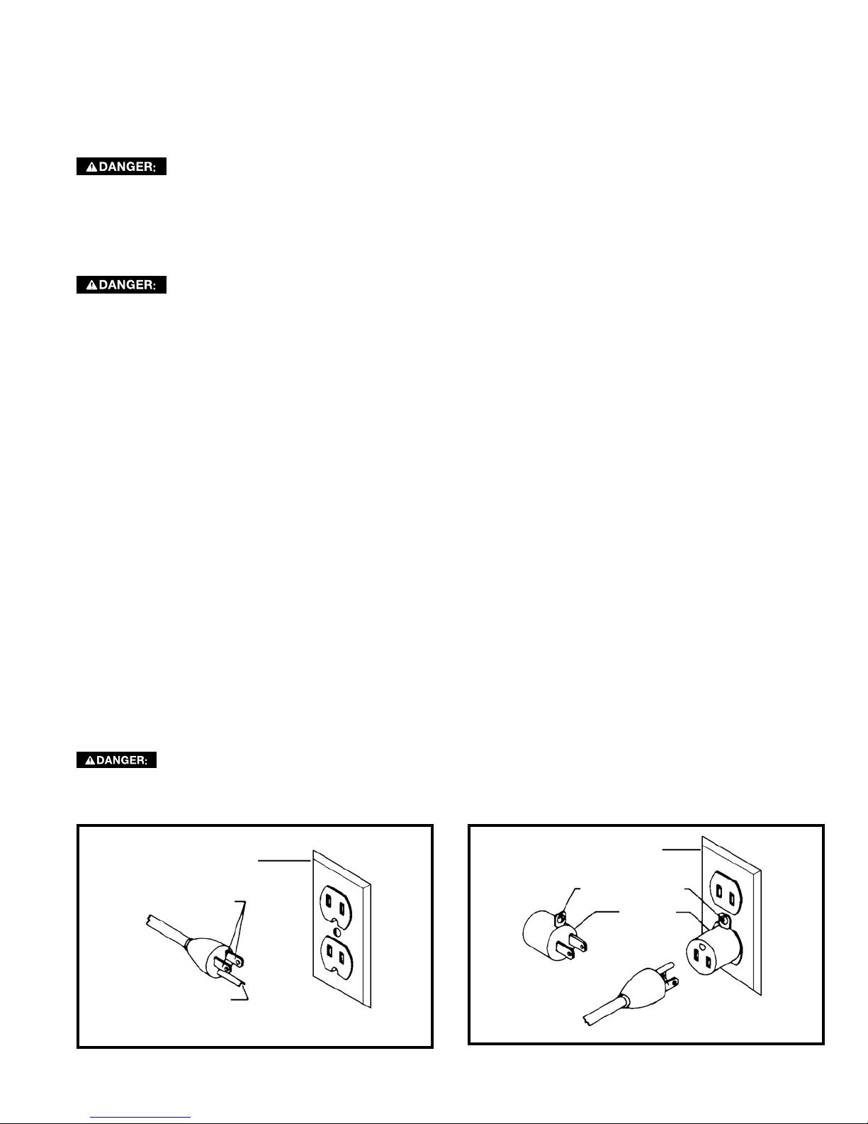
Use only 3-wire extension cords that have 3-prong grounding type plugs and matching 3-conductor receptacles that
accept the machine’s plug, as shown in Fig. A.
Repair or replace damaged or worn cord immediately.
2. Grounded, cord-connected machines intended for use on a supply circuit having a nominal rating less than
150 volts:
If the machine is intended for use on a circuit that has an outlet that looks like the one illustrated in Fig. A, the
machine will have a grounding plug that looks like the plug illustrated in Fig. A. A temporary adapter, which looks like
the adapter illustrated in Fig. B may be used to connect this plug to a matching 2-conductor receptacle as shown
in Fig. B, if a properly grounded outlet is not available. The temporary adapter should be used only until a properly
grounded outlet can be installed by a qualified electrician. The green-colored rigid ear, lug, and the like, extending
from the adapter must be connected to a permanent ground such as a properly grounded outlet box. Whenever the
adapter is used, it must be held in place with a metal screw.
NOTE: In Canada, the use of a temporary adapter is not permitted by the Canadian Electric Code.
In all cases, make certain that the receptacle in question is properly grounded. If you are not sure,
have a qualified electrician check the receptacle.
GROUNDED OUTLET BOX
CURRENT
CARRYING
PRONGS
GROUNDING BLADE
IS LONGEST OF THE 3 BLADES
Fig. A Fig. B
GROUNDED OUTLET BOX
GROUNDING MEANS
ADAPTER
5
Page 6
EXTENSION CORDS
Use proper extension cords. Make
sure your extension cord is in good condition and
is a 3-wire extension cord which has a 3-prong
grounding type plug and matching receptacle which
will accept the machine’s plug. When using an
extension cord, be sure to use one heavy enough to
carry the current of the machine. An undersized cord
will cause a drop in line voltage, resulting in loss
of power and overheating. Fig. D-1 or D-2, shows
the correct gauge to use depending on the cord
length. If in doubt, use the next heavier gauge. The
smaller the gauge number, the heavier the cord.
MINIMUM GAUGE EXTENSION CORD
RECOMMENDED SIZES FOR USE WITH STATIONARY ELECTRIC MACHINES
Total
Ampere
Rating Volts
0-6 120
0-6 120 25-50 16 AWG
0-6 120 50-100 16 AWG
0-6 120 100-150 14 AWG
6-10 120
6-10 120 25-50 16 AWG
6-10 120 50-100 14 AWG
6-10 120 100-150 12 AWG
10-12 120
10-12 120 25-50 16 AWG
10-12 120 50-100 14 AWG
10-12 120 100-150 12 AWG
12-16 120
12-16 120 25-50 12 AWG
12-16 120
Length of
Cord in
Feet
up to
25 18 AWG
up to
25 18 AWG
up to
25 16 AWG
up to
GREATER THAN 50 FEET NOT RECOMMENDED
Fig. D-1
Gauge of Extension
Cord
25 14 AWG
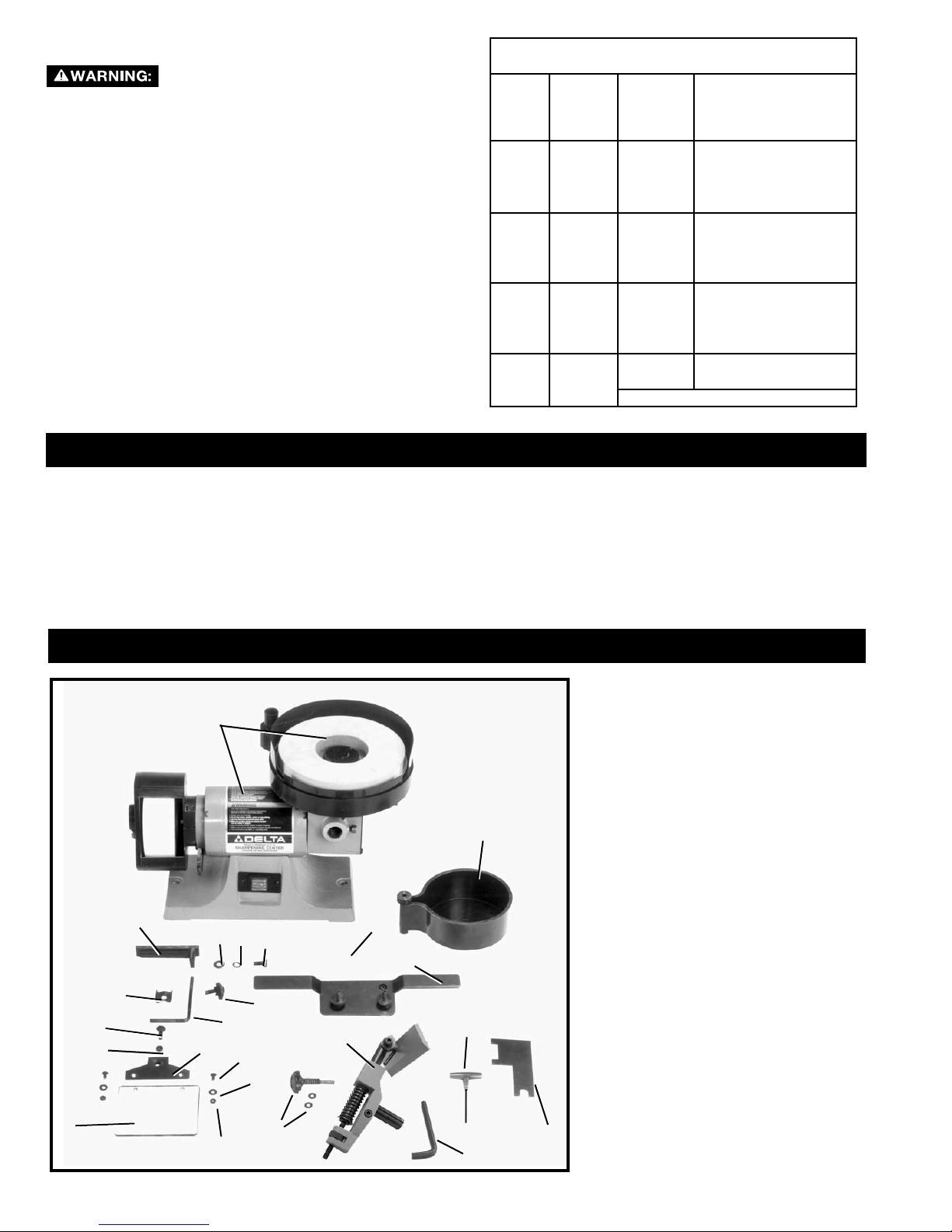
FUNCTIONAL DESCRIPTION
FOREWORD
The Delta Industrial Sharpening Center Model 23-710 has a 1/5 HP motor. It also comes with a 5” diameter, 120 grit
aluminum oxide dry wheel, an 8” diameter, 1000-grit wet wheel, a tool rest and base, a sliding tool holder, a water tank,
eye shield and wrenches.
NOTICE: The manual cover illustrates the current production model. All other illustrations contained in the manual are
representative only and may not depict the actual labeling or accessories included. These are intended to illustrate
technique only.
23
17
18
14
10
19
11
1
22
15
12
20
16
21
13
CARTON CONTENTS
2
4
3
5
6
8
7
1. Sharpening Center
2. Water Tank
3. Tool and Chisel Holder
4. Wheel Dressing Stone
5. Tool and Chisel Holder Base
Assembly
6. Tilting Screw and Spring for
Tool and Chisel Holder w/
(2) Flat Washers
7. 6mm Allen wrench
8. 6mm Allen Wrench
9. Wrench
10. Tool Rest for Dry Wheel
11. Flat Washer
12. Lockwasher
13. 5/8” Long Hex Head Screw
14. Eyeshield Clamp Bracket
15. Eyeshield Mounting Rod
16. Eyeshield Lock Knob
17. 3/4” Long Carriage Head Bolt
18. 1/4-20 Hex Nut
19. Eyeshield Frame
20. 1/2” Long, Round Head Screw
(2)
21. Flat Washer (2)
22. #10-24 Hex Nut (2)
9
23. Eyeshield
6
Page 7
UNPACKING AND CLEANING
Carefully unpack the machine and all loose items from the shipping container(s). Remove the rust-preventative oil from
unpainted surfaces using a soft cloth moistened with mineral spirits, paint thinner or denatured alcohol.
Do not use highly volatile solvents such as gasoline, naphtha, acetone or lacquer thinner for cleaning your
machine.
After cleaning, cover the unpainted surfaces with a good quality household floor paste wax.
ASSEMBLY
To reduce the risk of injury, turn unit off and disconnect it from power source before installing and remov-
ing accessories, before adjusting or when making repairs. An accidental start-up can cause injury.
ASSEMBLY TOOLS REQUIRED
Screw driver (not supplied)
Open-end wrenches (not supplied)
Hex Wrenches (not supplied)
ASSEMBLY TIME ESTIMATE
Assembly for this machine takes approximately 1 hour.
C
D
E
Fig. 3
B
C
B
D
E
A
A
F
A
G
H
B
Fig. 4
F
F
J
K
Fig. 5
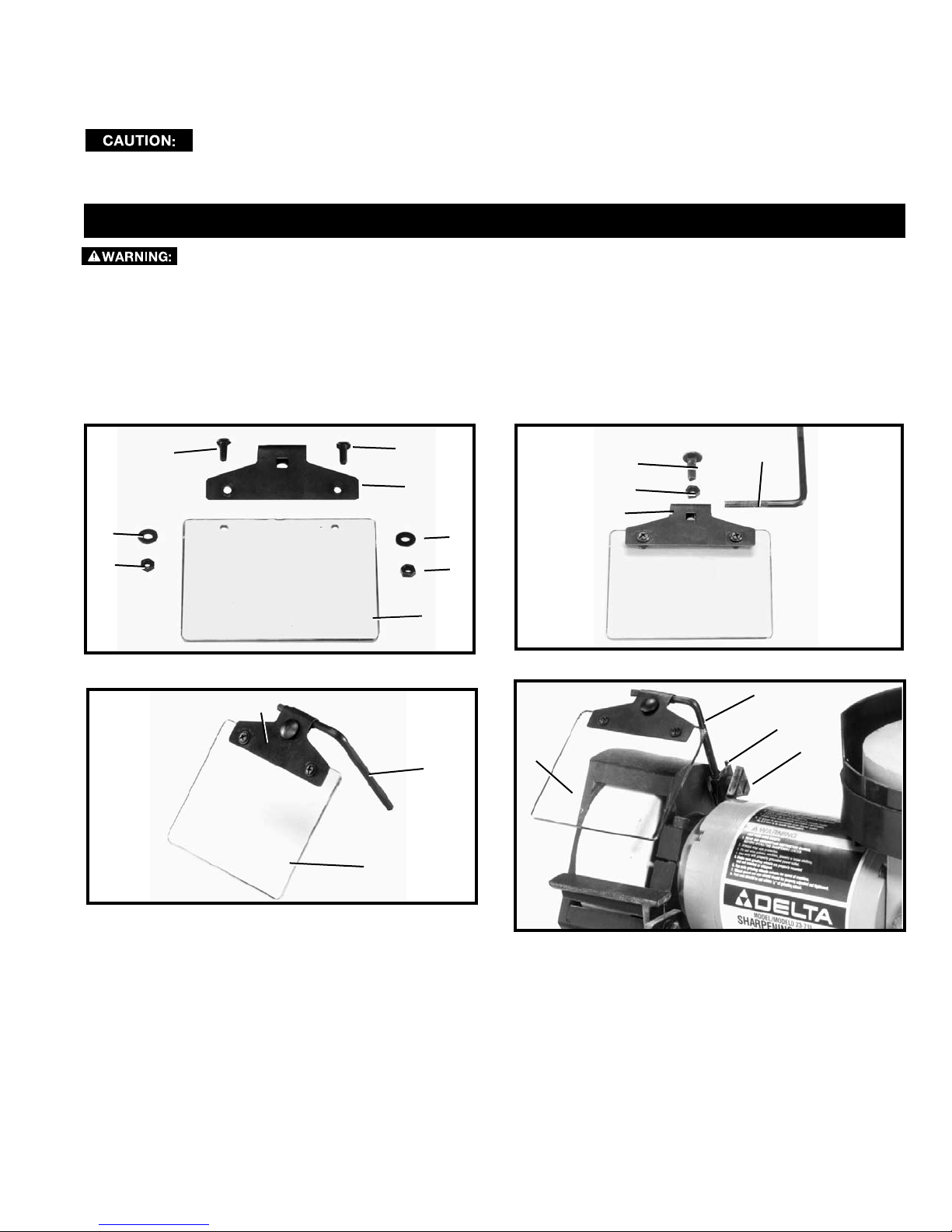
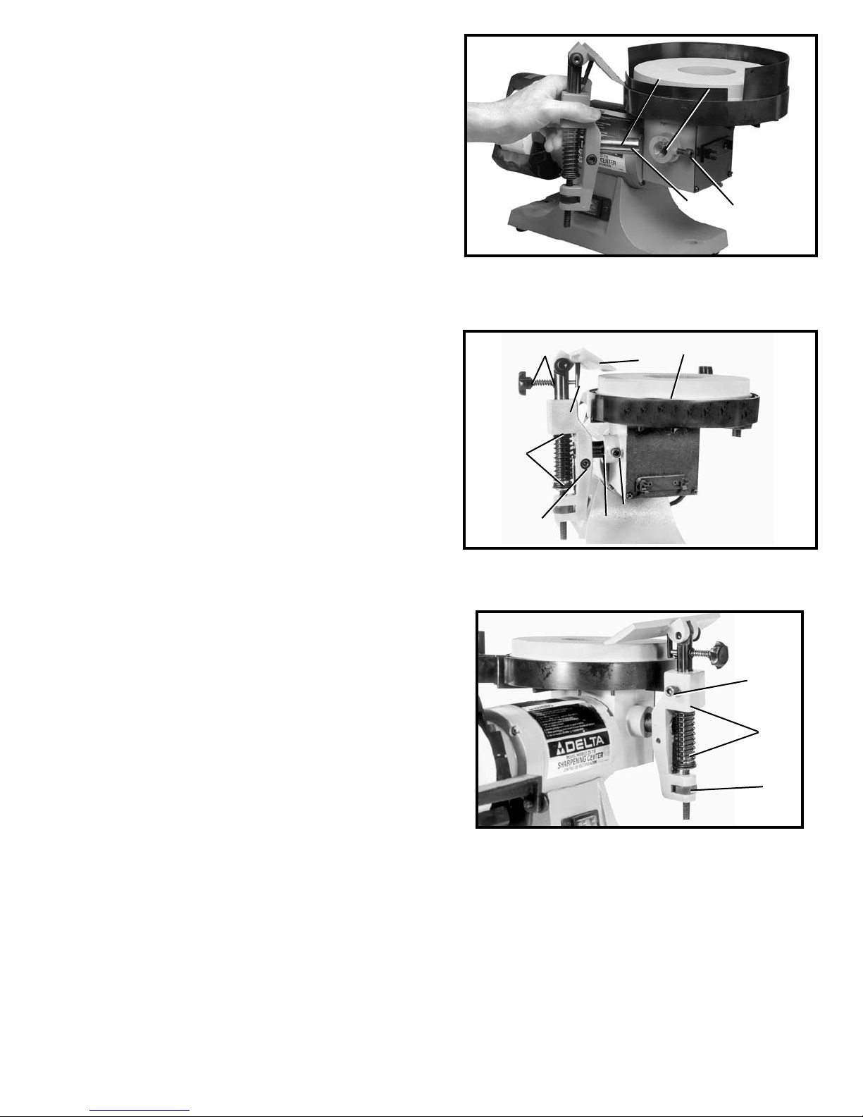
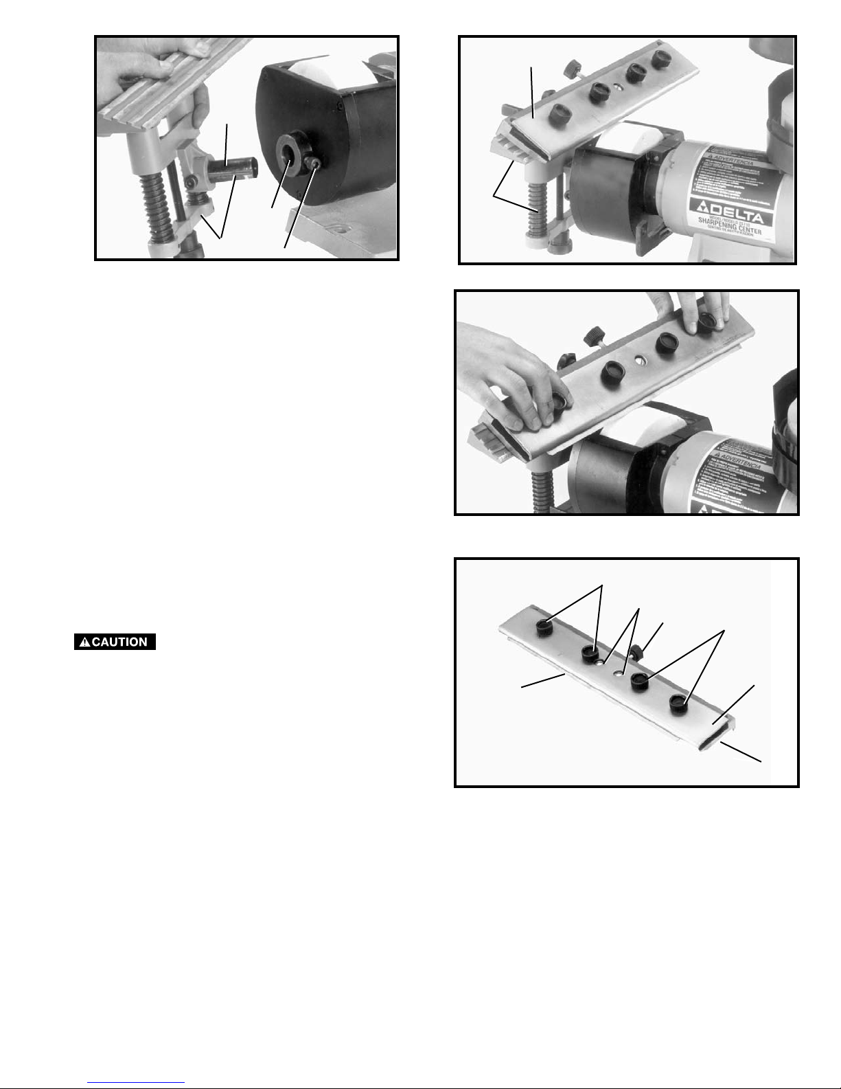
ASSEMBLING AND ADJUSTING EYESHIELD
1. Position eyeshield (A) Fig. 3, under lip of frame (B). Line up holes in eyeshield (A) with holes in frame (B) and fasten
eyeshield to frame using two 1/2” long round head screws (C), flat washers (D) and hex nuts (E). Place flat washer
on round head screw, place screw through hole and then fasten hex nut to screw under the frame.
2. Insert short end of eyeshield mounting rod (F) Fig. 4, into top of frame (B) and fasten in place with the 3/4” long carriage head bolt (G) and hex nut (H).
3. Figure 5, illustrates the mounting rod (F), frame (B) and eyeshield (A) assembled.
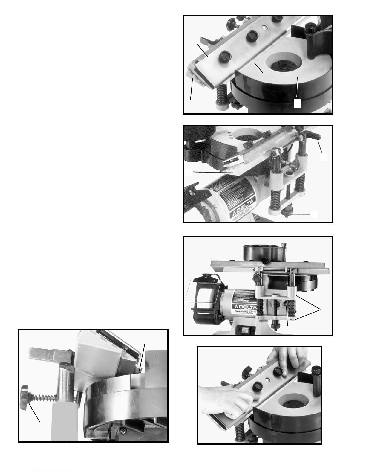
4. Assemble the long end of eyeshield mounting rod (F) Fig. 6, to the side of the dry wheel guard using clamp bracket
(J) and lock knob (K). The eyeshield (A) is fully adjustable to any position by moving shield (A) or loosening lock knob
(K) and repositioning mounting rod (F).
Fig. 6
7
Page 8
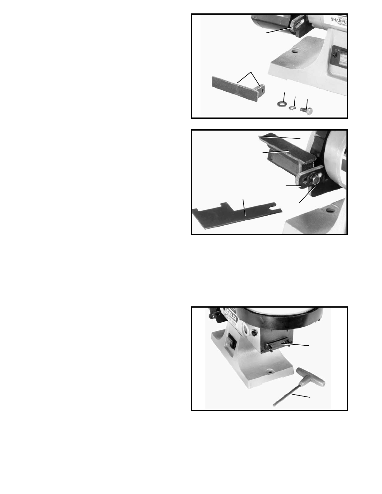
ASSEMBLING AND
ADJUSTING TOOL REST
FOR DRY WHEEL
B
1. Assemble dry wheel tool rest (A) Fig. 7, to mounting
arm (B) using flat washer (C), lockwasher (D) and 5/8”
long hex head screw (E). Place a lockwasher then a
flat washer on the hex head screw, then assemble
tool rest to mounting arm as shown in Fig. 8.
2. Figure 8, illustrates dry wheel tool rest (A) assembled
to mounting arm (B). Wrench (F) supplied, is used to
tighten screw (E).
3. The tool rest (A) Fig. 8, is adjustable so the inside
edge of the tool rest can be positioned as close to
the grinding wheel (H) as possible, giving maximum
support to the piece that is being ground. Always
maintain a distance of 1/8” or less between the
grinding wheel (H) and inside edge of tool rest (A). As
the grinding wheel wears down to a smaller diameter,
readjust the tool rest closer to the wheel by loosening
screw (E), moving tool rest (A) inward and tightening
screw (E) using wrench (F). The tool rest (A) can also
be rotated to any desired angle by loosening screw
(E), rotating tool rest (A) and tightening screw. Rotate
dry wheel (H) making certain wheel does not contact
tool rest (A).
A
C
D
E
Fig. 7
H
A
B
F
E
Fig. 8
WRENCH HOLDING BRACKET
1. Wrench (D) Fig. 10, can be stored in bracket (A)
when not in use.
A
D
Fig. 10
8
Page 9
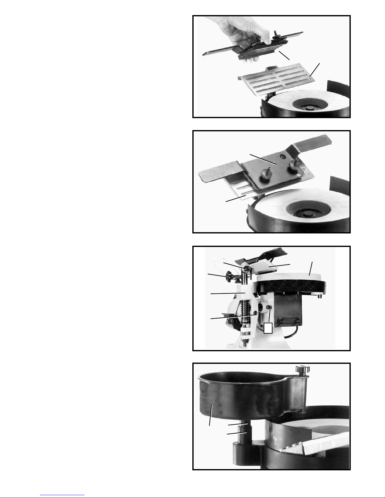
ASSEMBLING AND ADJUSTING
TOOL AND CHISEL HOLDER
1. Take the tool and chisel holder base and insert its
mounting post (A) Fig. 11, into hole (B) in the front of
the machine, and tighten screw (C) against groove (E)
of mounting post. Use the provided wrench (D) Fig.
10.
2. Loosen screw (C) Fig. 13, move tool and chisel holder to desired position and tighten screw (C).
3. Place flat washer, spring and another flat washer
onto the tilting screw knob. Thread tilting screw and
spring assembly (H) Fig. 13, into hole in post. NOTE:
End of screw (H) contacts lever (R) and this screw is
used to tilt the tool rest base (J).
A
Fig. 11
H
R
J
B
E
G
C
4. To level tool and chisel holder base (J) Fig. 13, with
the set grinding wheel (G), loosen screw (F) with supplied wrench, and turn complete base assembly (E)
until tool and chisel holder base (J) is level with wet
grinding wheel (G), and tighten screw (F).
5. To adjust the height of tool and chisel holder base
assembly (E) Fig. 14, loosen screw (S) and turn adjust ment knob (T). Tighten screw (S) after height adjustment is made.
E
C
F
A
Fig. 13
S
E
T
Fig. 14
9
Page 10
6. Place tool and chisel holder (K) Fig. 15, in position on
base (J).
7. Fig. 16, illustrates tool and chisel holder (K) in position on tool rest base (J).
8. To raise or lower the tool and chisel holder assembly
(E) Fig. 17, refer to STEP 5.
9. To tilt the tool and chisel holder (J) Fig.17, to conform
with the angle of the tool to be sharpened, loosen set
screw (N) and turn knob (H) as necessary. After angle
is set, tighten set screw (N).
10. To move the tool and chisel holder (J) Fig. 17, in or
out, loosen set screw (C), and slide assembly (E) in or
out as desired. After adjustment, tighten screw (C).
11. To level tool and chisel holder base (J) Fig. 17, with
the wet grinding wheel (G), loosen screw (F) with supplied wrench, and rotate complete base assembly (E)
until tool and chisel holder base (J) is level with wet
grinding wheel (G), and tighten screw (F).
K
Fig. 15
K
J
Fig. 16
N
H
E
J
J
G
ASSEMBLING AND ADJUSTING
WATER TANK
1. Insert stem (A) Fig. 18, of water tank (B) into holder
(C) as shown.
10
F
C
Fig. 17
A
B
C
Fig. 18
Page 11
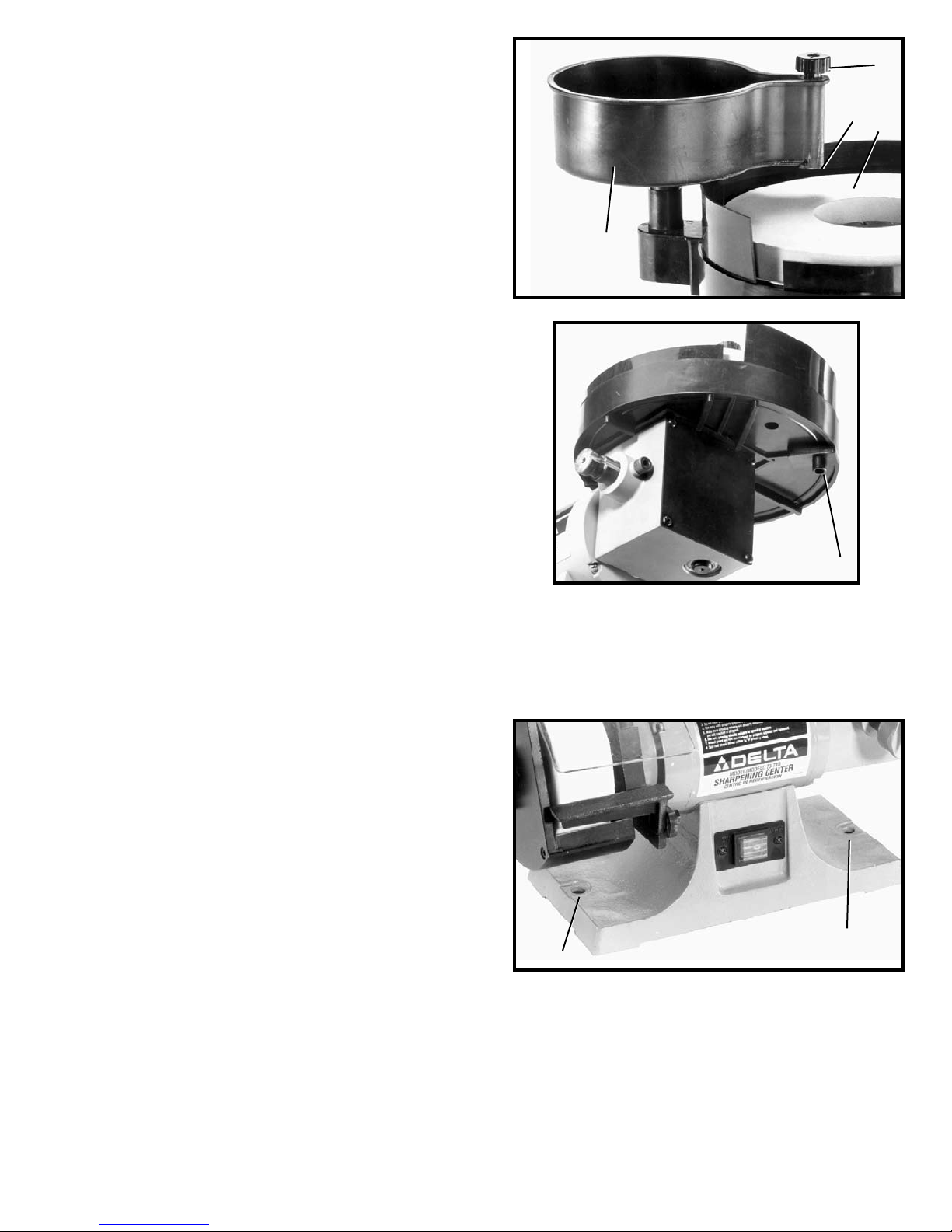
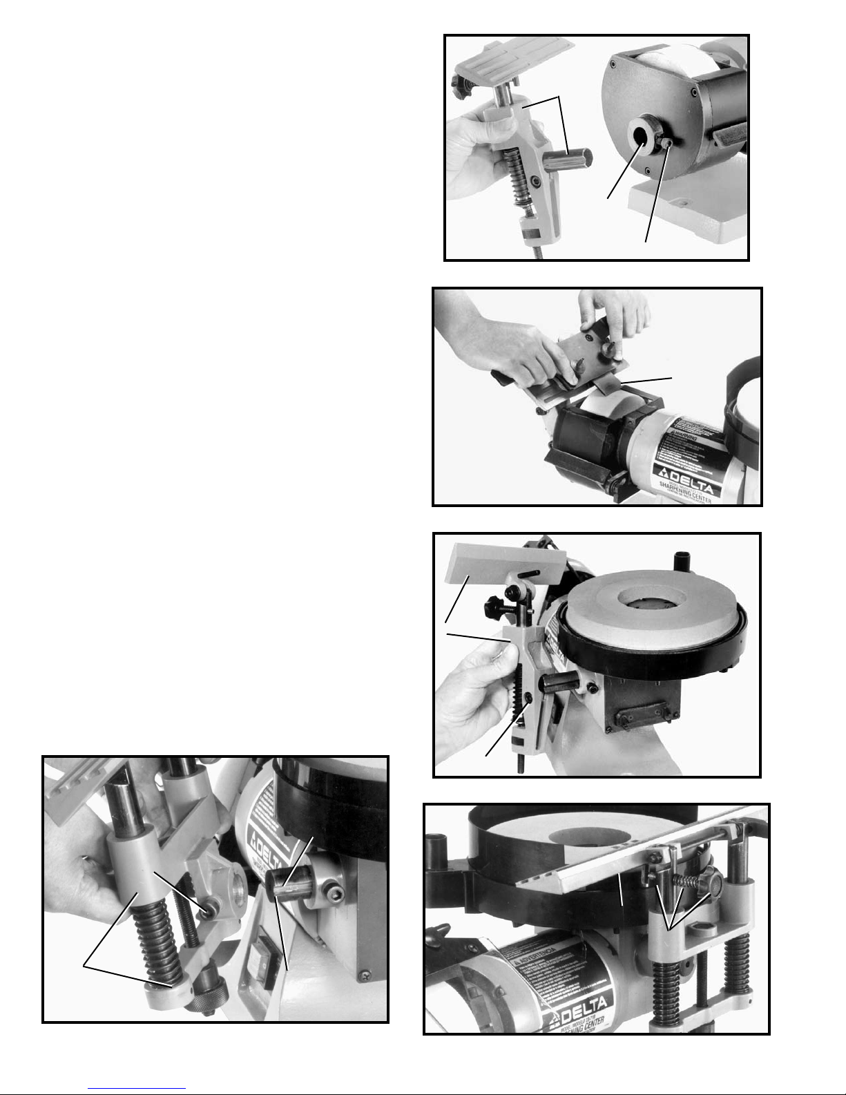
2. The water tank (B) Fig. 19, can be rotated to direct
the water from the spigot (D) onto the grinding wheel.
The ideal position of the spigot (D) would be to the
center (C) of the grinding wheel.
3. To control the flow of water from the spigot (D) Fig.
19, turn knob (E).
4. A drain (F) Fig. 20, is provided underneath the grinding wheel housing to dispose of water. Place a can or
suitable container underneath the drain (F).
E
D
C
B
Fig. 19
FASTENING SHARPENING CENTER
TO SUPPORTING SURFACE
If during operation there is any tendency for the machine
to tip over, slide or "walk" on the supporting surface, the
machine must be secured to the supporting surface. Two
holes, (A) Fig. 21, are provided for this purpose.
F
Fig. 20
A
A
Fig. 21
11
Page 12
OPERATION
To reduce the risk of injury, turn unit off and disconnect it from power source before installing and remov-
ing accessories, before adjusting or when making repairs. An accidental start-up can cause injury.
OPERATIONAL CONTROLS AND ADJUSTMENTS
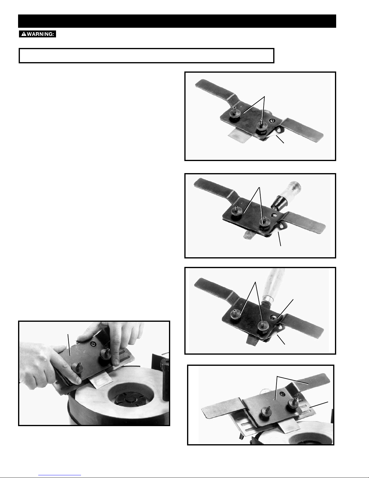
USING TOOL AND CHISEL HOLDER
The tool and chisel holder is supplied as standard
equip ment with your sharpening center and is ideal for
sharp en ing wood chisels, plane irons, some lathe turning tools, etc. To use the tool and chisel holder, proceed
as follows.
1. Loosen the two clamp knobs (A) Figs. 25, 26 and 27,
and insert the tool or chisel between the clamp as
shown, making sure the edge of the tool or chisel
is against the inside of the protractor gage (B). Fig.
25 illustrates a plane iron; Fig. 26 illustrates a wood
chisel; and Fig. 27 illustrates a lathe turning tool inserted between the clamp of the tool and chisel
holder. Then tighten the two clamp knobs (A). Adjust
the protractor gage (B) so that the cutting edge of
the tool to be sharpened is the correct angle for the
grinding wheel. Loosen screw (C) Fig. 27, and adjust
the protractor gage (B) as shown. Tighten screw (C)
after angle is obtained.
2. Place the complete tool and chisel holder assembly
(D) Fig. 28, on the tool rest base (E) as shown. Adjustment of the tool rest is explained in section “ASSEMBLING AND ADJUSTING TOOL AND CHISEL
HOLDER.”
3. Figure 29, illustrates a plane iron being sharpened
using the tool and chisel holder (D) supplied with the
machine.
A
B
Fig. 25
A
B
Fig. 26
A
D
Fig. 29
C
B
Fig. 27
D
E
Fig. 28
12
Page 13
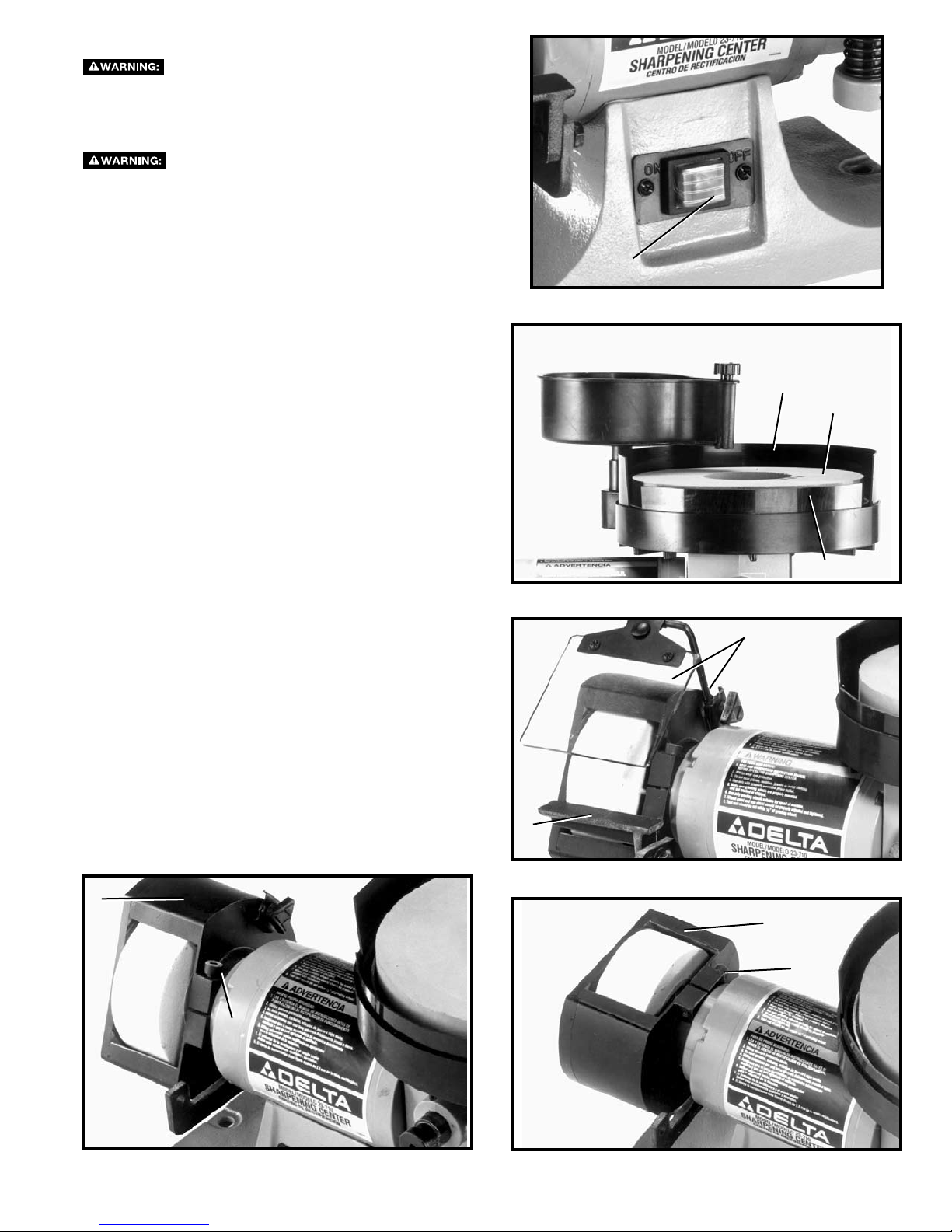
STARTING AND STOPPING MACHINE
Make sure that the switch is in the “OFF”
position before plugging cord into outlet. Do not touch
the plug’s metal prongs when unplugging or plugging
in the cord.
In the event of a power outage (such as
a breaker or fuse trip), always move the switch to the
“OFF” position until the main power is restored.
The switch (A) Fig. 30, is located on the front of the
grinder base inside a water resistant enclosure. To turn
the machine “ON” push the left hand portion of the
switch. To turn the machine “OFF” push the right hand
portion of the switch.
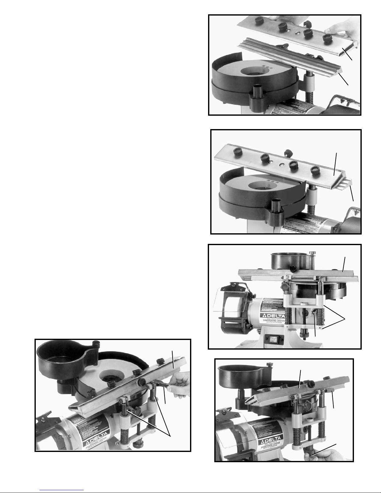
ADJUSTING
SPLASH GUARDS
Two adjustable splash guards (A) and (B) Fig. 31, are provid ed with your sharpening center. The height of the front
splash guard (A) should be adjusted so the top edge of
the guard (A) is slightly below the grinding surface (C) of
the wheel. The rear splash guard should be positioned
high, as shown. To adjust the splash guards, move the
guards manually.
A
Fig. 30
B
C
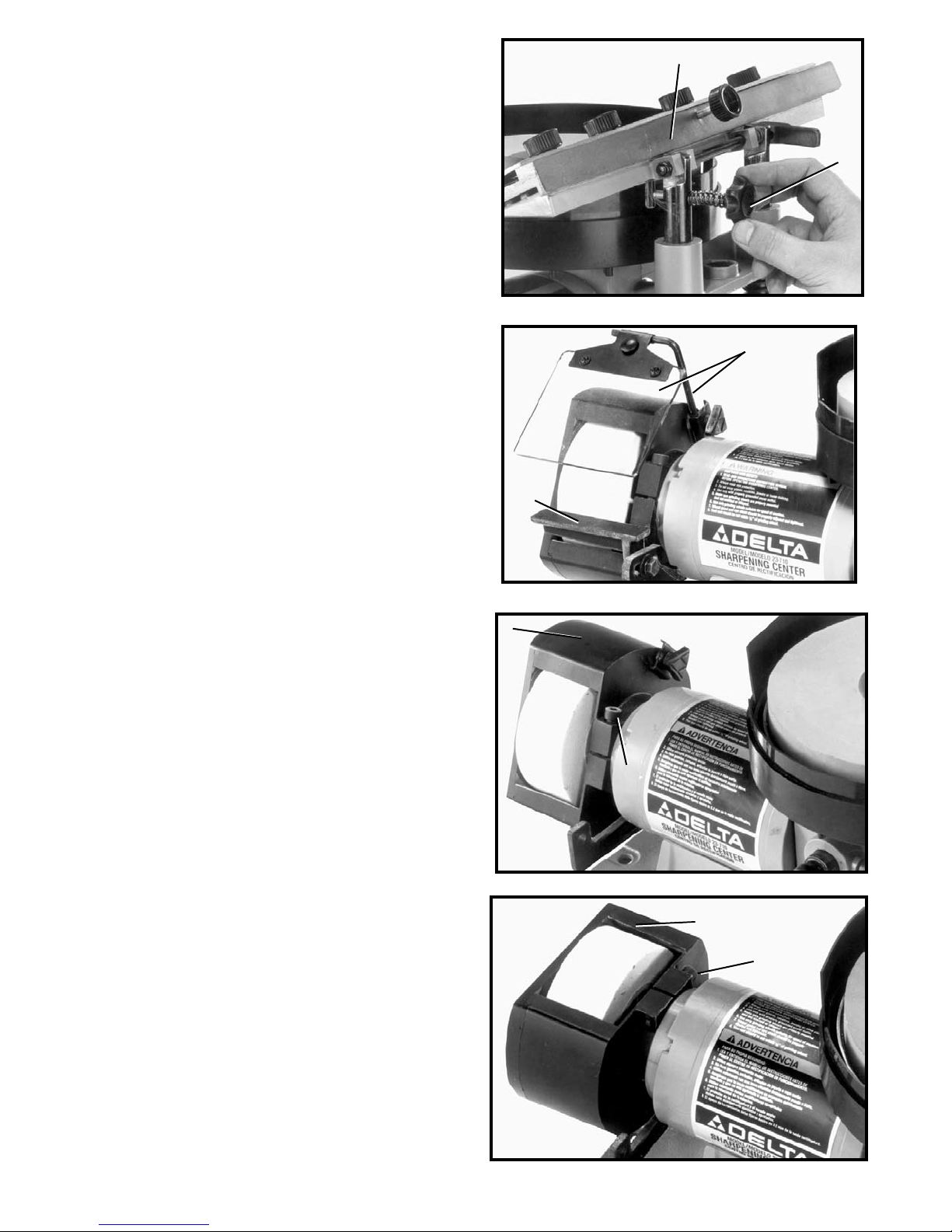
USING TOOL AND CHISEL HOLDER
ON DRY WHEEL
When sharp en ing chis els, plane irons, etc., that have
deep nicks, the cutting edge of the tool can first be rough
ground on the dry grinding wheel before fine sharpening
is per formed on the wet wheel. To use the tool and chisel
holder on the dry wheel, proceed as follows:
1. Remove the dry wheel tool rest (A) Fig. 32, and eye-
shield (B).
2. Loosen screw (C) Fig. 33, and rotate wheel guard (D)
to the rear, as shown in Fig. 34, and tighten screw
(C).
D
A
Fig. 31
B
A
Fig. 32
D
C
C
Fig. 34Fig. 33
13
Page 14
3. Remove the tool rest and mounting post (E) Fig. 35,
from the wet wheel side of the machine and insert
post of tool rest assembly into hole (F). Tighten screw
(G) into groove of mounting post. All controls and adjustments for the tool rest are explained in the section “ASSEMBLING AND AD JUST ING TOOL AND
CHISEL HOLDER.”
4. Figure 36, illustrates a rough grinding operation on a
plane iron (H) using the dry wheel.
E
F
G
Fig. 35
ASSEMBLING OPTIONAL
ACCESSORY 23-715 SLIDING TOOL
REST TO WET WHEEL
The 23-715 Sliding Tool Rest is available as an accessory for your sharpening center and is especially suited
for sharpening jointer and planer knives. To assemble the
23-715 Sliding Tool Rest, proceed as follows:
1. Loosen screw (A) Fig. 37, and remove tool and chisel
holder assembly (B) as shown.
2. Assemble slid ing table tool rest base (E) Fig. 38,
to mounting post (A) and tighten screw (F) against
groove (G) in mounting post.
3. Place flat washer, spring and another flat washer
onto the tilting screw knob included with the 23-715.
Thread tilting screw and spring assembly (H) Fig. 39,
into hole in left post.
H
Fig. 36
B
A
F
E
Fig. 38
Fig. 37
G
J
H
A
Fig. 39
14
Page 15
4. Place sliding tool rest (K) Fig. 40, in position on base
(J).
5. Fig. 41, illustrates sliding tool rest (K) in position on
tool rest base (J).
K
J
Fig. 40
K
6. To level sliding tool rest (K) Fig. 42, with the wet grinding wheel, loosen screw (L), rotate complete tool rest
base (E) right or left until tool rest (K) is level with the
wet grinding wheel and tighten screw (L).
7. To raise sliding tool rest (K) Fig. 43, unlock two posts
(M) by moving clamp lever (N) to the right, as shown.
Rotate knob (O) Fig. 44, clockwise to raise, or counterclockwise to lower the tool rest (K). After the height
of tool rest (K) is set, move clamp lever (N) to the left
in the locked position.
K
J
Fig. 41
K
E
L
Fig. 42
K
Fig. 43
N
M
N
O
Fig. 44
15
Page 16
8. To tilt the sliding tool rest (K) Fig. 45, to conform with
the angle of the knife to be sharpened, turn the tool
rest tilting knob (P).
USING ACCESSORY 23-715 SLIDING
TOOL REST ON DRY WHEEL
When sharpening planer or jointer knives that have deep
nicks, the knives can first be rough ground on the dry
grinding wheel, using the sliding tool rest, before fine
sharp en ing is performed on the wet wheel. To use the
sliding tool rest on the dry wheel, proceed as follows:
K
P
Fig. 45
B
1. Remove the dry wheel tool rest (A) Fig. 46, and eyeshield (B).
2. Loosen screw (C) Fig. 47, and rotate wheel guard (D)
to the rear, as shown in Fig. 48, and tighten screw
(C).
A
Fig. 46
D
C
Fig. 47
D
C
Fig. 48
16
Page 17
H
J
E
F
E
Fig. 49 Fig. 50
3. Remove sliding tool rest and mounting post (E) Fig.
49, from the wet wheel side of the machine and insert
post of tool rest assembly into hole (F). Tighten screw
(G) into groove (J) of mounting post (E).
4. Fig. 50, illustrates the sliding tool rest (E) assembled
to the dry wheel side of the machine with the knife
holder (H) positioned on the tool rest. All controls and
adjustments for the sliding tool rest are explained in
the section of this manual titled “ASSEMBLING ACCESSORY 23-715 SLIDING TOOL REST TO WET
WHEEL.”
5. Fig. 51, illustrates a rough grinding operation on a
planer knife using the dry wheel.
G
USING THE TOOL REST WITH PLANER OR JOINTER KNIVES
CARE MUST BE TAKEN WHEN HANDLING PLANER OR JOINTER KNIVES, AS THE CUTTING EDGES ARE VERY SHARP. WEAR PROTECTIVE
GLOVES WHEN HANDLING THE KNIVES.
1. Loosen four lock knobs (A) Fig. 52 and two screws
Fig. 51
A
E
F
B
A
C
(E) and carefully slide knife (B) between the top and
bottom pieces (C) and (D) of the sliding tool rest. It is
important that the bevel edge of the knife (B) is in the
down position. Also, be sure the back of the knife is
pushed in so it sits against the knife adjustment bar
inside the tool rest.
2. Make sure knife (B) Fig. 52, pro trudes out from the
top and bottom pieces (C) and (D) of the sliding tool
rest at least 5/16”. If it does not, rotate adjusting
knob (F) Fig. 50, clockwise to move the knife outward
or coun ter clock wise to move the knife in ward. When
moving the knife inward, carefully push the knife (B)
inward with a piece of scrap wood while turning the
knob (F) counterclockwise. When you are certain the
knife pro trudes 5/16” outward from the sliding tool
rest, tighten two screws (E) and four knobs (A).
D
Fig. 52
17
Page 18
3. Place sliding tool rest (G) Fig. 53, onto the tool rest
base (H) as shown.
4. Adjust the height of tool rest base (H) Fig. 54, by
moving locking lever (J) to the right and turning raising and lowering knob (K) until knife (B) Fig. 53, lightly
touches grinding wheel (L). Then move locking lever
(J) Fig. 54 to the left to lock in place.
5. Check to see if the knife (B) Fig. 53, is parallel with
grinding wheel (L) at both ends when the knife is just
contacting the wheel.
G
B
H
Fig. 53
H
L
J
6. If the knife (B) Fig. 53, is not parallel with the grinding wheel, loosen screw (M) Fig. 55, and rotate tool
rest base (N) until knife is parallel with grinding wheel.
Then tighten screw (M) Fig. 55.
7. Check to see if the bevel edge of the knife (B) Fig. 56,
is flat on the grinding wheel. If an adjustment is necessary, turn tilting screw (O) Fig. 56, until the edge of
the knife is flat on the grinding wheel.
8. Fig. 57, illustrates a typical grind ing operation of a
jointer or planer knife.
B
K
Fig. 54
N
M
Fig. 55
O
Fig. 56
Fig. 57
18
Page 19
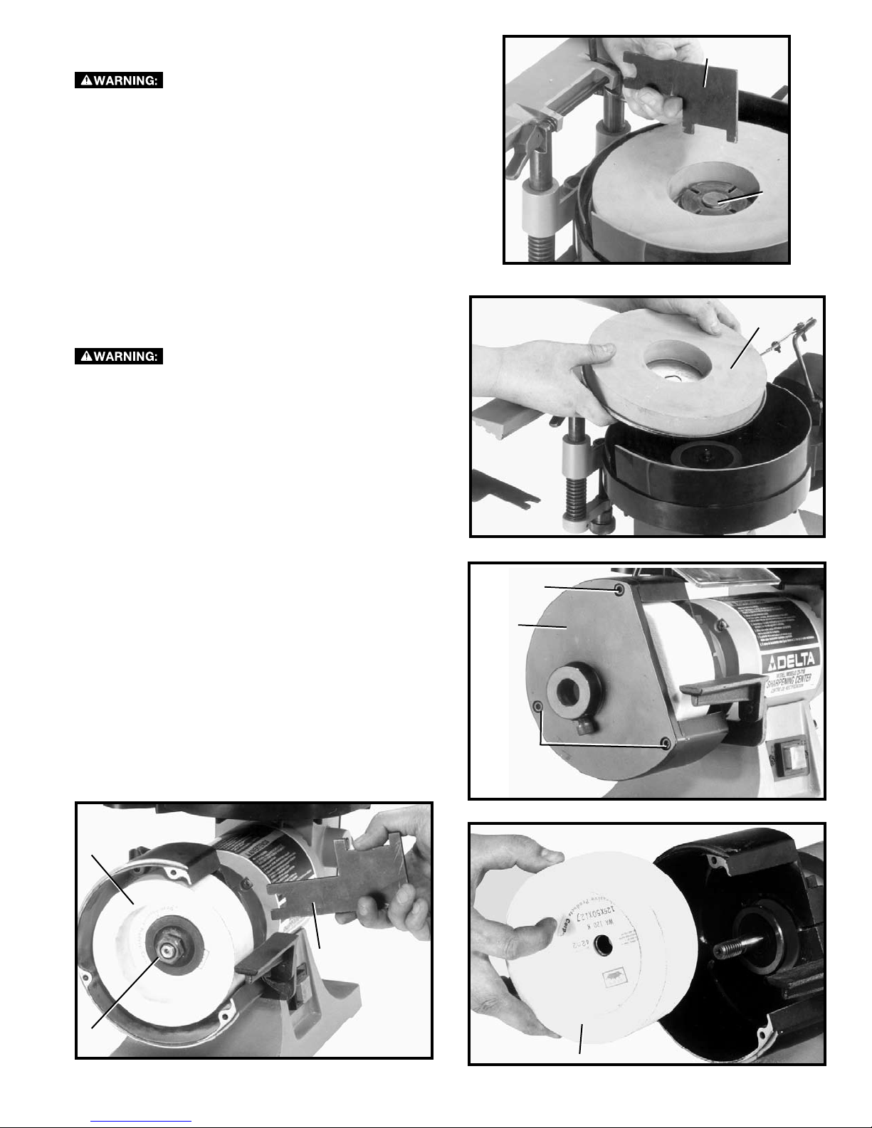
REPLACING WET GRINDING WHEEL
To reduce the risk of injury, turn unit off and
disconnect it from power source before installing and removing accessories, before adjusting or when making
repairs. An accidental start-up can cause injury.
1. Using the wrench (A) Fig. 58, supplied, remove the
wheel locking nut (B).
2. Remove and replace the wet wheel (C) as shown in
Fig. 59.
A
B
Fig. 58
REPLACING DRY GRINDING WHEEL
To reduce the risk of injury, turn unit off and
disconnect it from power source before installing and removing accessories, before adjusting or when making
repairs. An accidental start-up can cause injury.
1. Remove three screws (A) Fig. 60, and side cover (B).
2. Using wrench (C) Fig. 61, supplied, hold motor shaft
on inside of grinding wheel (D) to keep shaft from
turning and remove wheel nut (E). Use a 13/16 wrench
(not provided).
3. Remove grinding wheel (D), as shown in Fig. 62.
C
Fig. 59
A
B
D
E
Fig. 61
A
Fig. 60
C
D
Fig. 62
19
Page 20

DRESSING THE DRY GRINDING
WHEEL
A stick type dresser (A) Fig. 63, is supplied with your
sharpening center to dress the dry grinding wheel. Bring
the dresser stick (A) forward on the tool rest until it just
touches the high point of the face of the wheel and dress
the wheel by moving the dresser stick back and forth.
Repeat this operation until the face of the wheel is clean
and the corners of the wheel are square.
A
Fig. 63
TROUBLESHOOTING
For assistance with your machine, visit our website at www.deltaportercable.com for a list of service centers or call the
DELTA Machinery help line at 1-800-223-7278 (In Canada call 1-800-463-3582).
MAINTENANCE
To reduce the risk of injury, turn unit off and disconnect it from power source before installing and removing
accessories, before adjusting or when making repairs. An accidental start-up can cause injury.
KEEP MACHINE CLEAN
Periodically blow out all air passages with dry compressed air. All plastic parts should be cleaned with a soft damp
cloth. NEVER use solvents to clean plastic parts. They could possibly dissolve or otherwise damage the material.
Wear certified safety equipment for eye, hearing and respiratory protection while using compressed air.
FAILURE TO START
Should your machine fail to start, check to make sure the prongs on the cord plug are making good contact in the
outlet. Also, check for blown fuses or open circuit breakers in the line.
20
Page 21

SERVICE
REPLACEMENT PARTS
Use only identical replacement parts. For a parts list or to order parts, visit our website at
com.
You can also order parts from your nearest factory-owned branch, or by calling our Customer Care Center at 1-800-223-7278
to receive personalized support from highly-trained technicians.
SERVICE AND REPAIRS
All quality tools will eventually require servicing and/or replacement of parts. For information about Delta Machinery, its factoryowned branches, or an Authorized Warranty Service Center, visit our website at www.deltaportercable.com or call our Customer
Care Center at 1-800-223-7278. All repairs made by our service centers are fully guaranteed against defective material and
workmanship. We cannot guarantee repairs made or attempted by others.
You can also write to us for information at Delta Machinery, 4825 Highway 45 North, Jackson, Tennessee 38305 - Attention:
Product Service. Be sure to include all of the information shown on the nameplate of your tool (model number, type, serial number,
etc.)
www.deltaportercableservicenet.
ACCESSORIES
Since accessories other than those offered by Delta have not been tested with this product, use
of such accessories could be hazardous. For safest operation, only Delta recommended accessories should be
used with this product.
A complete line of accessories is available from your Delta Supplier, Porter-Cable • Delta Factory Service Centers, and
Delta Authorized Service Stations. Please visit our Web Site www.deltaportercable.com for a catalog or for the name
of your nearest supplier.
WARRANTY
To register your tool for warranty service visit our website at www.deltaportercable.com.
Two Year Limited New Product Warranty
Delta will repair or replace, at its expense and at its option, any new Delta machine, machine part, or machine accessory which in normal
use has proven to be defective in workmanship or material, provided that the customer returns the product prepaid to a Delta factory service
center or authorized service station with proof of purchase of the product within two years and provides Delta with reasonable opportunity
to verify the alleged defect by inspection. For all refurbished Delta product, the warranty period is 180 days. Delta may require that electric
motors be returned prepaid to a motor manufacturer’s authorized station for inspection and repair or replacement. Delta will not be responsible
for any asserted defect which has resulted from normal wear, misuse, abuse or repair or alteration made or specifically authorized by anyone
other than an authorized Delta service facility or representative. Under no circumstances will Delta be liable for incidental or consequential
damages resulting from defective products. This warranty is Delta’s sole warranty and sets forth the customer’s exclusive remedy, with respect
to defective products; all other warranties, express or implied, whether of merchantability, fitness for purpose, or otherwise, are expressly
disclaimed by Delta.
LATIN AMERICA: This warranty does not apply to products sold in Latin America. For products sold in Latin America, see country specific
warranty information contained in the packaging, call the local company or see website for warranty information.
21
Page 22

LES INSTRUCTIONS IMPORTANTES DE SURETE
Lire toutes instructions d'avertissements et opération avant d'utiliser n'importe
quel outil ou n'importe quel équipement. En utilisant les outils ou l'équipement, les précautions de
sûreté fondamentales toujours devraient être suivies pour réduire le risque de blessure personnelle.
L'opération déplacée, l'entretien ou la modification d'outils ou d'équipement ont pour résultat la
blessure sérieux et les dommages de propriété. Il y a de certaines applications pour lequel outils et l'équipement
sont conçus. La Delta Machinery recommande avec force que ce produit n'ait pas modifié et/ou utilisé pour
l'application autrement que pour lequel il a été conçu.
Si vous avez n'importe quelles questions relatives à son application n'utilisent pas le produit jusqu'à ce que vous
avez écrit Delta Machinery et nous vous avons conseillé. La forme en ligne de contact à www.deltaportercable.com
Courrier Postal: Technical Service Manager, Delta Machinery, 4825 Highway 45 North, Jackson, TN 38305.
125 Mural St. Suite 300, Richmond Hill, ON, L4B 1M4.
Information en ce qui concerne l'opération sûre et correcte de cet outil est disponible des sources suivantes:
• Power Tool Institute, 1300 Sumner Avenue, Cleveland, OH 44115-2851 ou en ligne www.powertoolinstitute.org
• National Safety Council, 1121 Spring Lake Drive, Itasca, IL 60143-3201
• American National Standards Institute, 25 West 43rd Street, 4 floor, New York, NY 10036 www.ansi.org - ANSI
01.1 Safety Requirements for Woodworking Machines
• U.S. Department of Labor: www.osha.gov
CONSERVER CES DIRECTIVES
Dans Canada,
MESURES DE SÉCURITÉ - DÉFINITIONS
Ce guide contient des renseignements importants que vous deviez bien saisir. Cette information porte sur VOTRE SÉCURITÉ
et sur LA PRÉVENTION DE PROBLÈMES D’ÉQUIPEMENT. Afin de vous aider à identifier cette information, nous avons
utilisé les symboles ci-dessous. Veuillez lire attentivement ce guide en portant une attention particulière à ces sections.
Indique une situation dangereuse imminente qui, si elle n’est pas évitée, causera la mort ou des blessures
graves.
Indique une situation potentiellement dangereuse qui, si elle n’est pas évitée, pourrait se solder par un décès
ou des blessures graves.
Indique une situation potentiellement dangereuse qui, si elle n’est pas évitée pourrait se solder par des bles-
sures mineures ou modérées.
Utilisé sans le symbole d’alerte à la sécurité, indique une situation potentiellement dangereuse qui, si elle n'est
pas évitée pourrait se solder par des dommages à la propriété.
Certaines poussières produites par les travaux de ponçage, de sciage, de meulage,
de perçage et par toute autre activité de construction contiennent des produits chimiques reconnus par l’État
de la Californie comme pouvant causer le cancer, des anomalies congénitales ou d’autres problèmes liés aux
fonctions reproductrices. Voici quelques exemples de ces produits chimiques :
• leplombdespeinturesàbasedeplomb,
• lasilicecristallineprovenantdesbriques,ducimentetd’autresproduitsdemaçonnerieainsique,et
• l’arsenicetlechromeissusduboistraitéchimiquement.
Les risques reliés à l’exposition à ces produits chimiques varient selon la fréquence à laquelle l’utilisateur
effectue ce type de travail. Pour réduire l’exposition à ces produits chimiques : travailler dans un endroit
bien ventilé et porter un équipement de sécurité approuvé, notamment un masque antipoussières conçu
spécialement pour filtrer les particules microscopiques.
Page 23

RÈGLES DE SÉCURITÉ GÉNÉRALES
L’inobservation de ces règles peut conduire à des blessures graves.
1. POUR SA SÉCURITÉ PERSONNELLE, LIRE LA NOTICE
D’UTILISATION, AVANT DE METTRE LA MACHINE EN
MARCHE, et pour aussi apprendre l’application et les limites de
la machine ainsi que les risques qui lui sont particuliers ainsi, les
possibilités d’accident et de blessures seront beaucoup réduites.
2. PORTEZ DES DISPOSITIFS DE PROTECTION DES YEUX
ET DE L'OUÏE. UTILISEZ TOUJOURS DES LUNETTES DE
SÉCURITÉ. Des lunettes ordinaires ne constituent PAS des
lunettes de sécurité. UTILISEZ DES ÉQUIPEMENTS DE
SÛRETÉ HOMOLOGUÉS. Les dispositifs de protection des
yeux doivent être conformes aux normes ANSI Z87.1. Les
dispositifs de protection de l'ouïe doivent être conformes aux
normes ANSI S3.19.
3. PORTER UNE TENUE APPROPRIÉE. Pas de cravates, de
gants, ni de vêtements amples. Enlever montre, bagues et autres
bijoux. Rouler les manches. Les vêtements ou les bijoux qui
se trouvent pris dans les pièces mobiles peuvent entraîner des
blessures.
4. NE PAS UTILISER LA MACHINE DANS UN ENVIRONNEMENT
DANGEREUX. L’utilisation d’outils électriques dans des
endroits humides ou sous la pluie peut entraîner des décharges
électriques ou une électrocution. Garder la zone de travail bien
éclairée pour éviter de trébucher ou d’exposer les doigts, les
mains ou les bras à une situation dangereuse.
5. GARDER LES OUTILS ET LES MACHINES EN PARFAIT
ÉTAT. Garder les outils affûtés et propres afin d’obtenir le meilleur
et le plus sûr rendement. Suivre les instructions pour lubrifier
et changer les accessoires. Les outils et les machines mal
entretenus peuvent se dégrader davantage, et/ou entraîner des
blessures.
6. INSPECTER LES PIÈCES POUR DÉCELER TOUT
DOMMAGE. Avant d’utiliser la machine, la vérifier pour voir
s’il n’y a pas de pièces endommagées. Vérifier l’alignement
des pièces mobiles et si ces pièces ne se coincent pas, la
rupture de pièces, ou toute autre condition pouvant en affecter
le fonctionnement. Toute pièce ou protecteur endommagé doit
être réparé ou remplacé. Les pièces endommagées peuvent
dégrader davantage la machine et/ou entraîner des blessures.
7. GARDER L’AIRE DE TRAVAIL PROPRE. Les zones et établis
encombrés favorisent les accidents.
8. GARDER LES ENFANTS ET LES VISITEURS À DISTANCE.
L’atelier est un lieu potentiellement dangereux. Les enfants et les
visiteurs peuvent se blesser.
9. ÉVITER LE DÉMARRAGE ACCIDENTEL. S’assurer que
l’interrupteur est sur « OFF » (ARRÊT) avant de brancher le
cordon. En cas de coupure de courant, placer l’interrupteur
à la position « OFF » (ARRÊT). Un démarrage accidentel peut
entraîner des blessures.
10. UTILISER LES DISPOSITIFS PROTECTEURS. Vérifier que tous
les dispositifs protecteurs sont bien en place, bien fixés et en bon
état de marche pour éviter les blessures.
11. ENLEVER LES CLÉS DE RÉGLAGE ET CELLES DE SERRAGE
AVANT DE METTRE LA MACHINE EN MARCHE. Les outils,
les chutes et les autres débris peuvent être projetés violemment
et blesser.
12. UTILISER LA BONNE MACHINE. Ne pas forcer la machine ou
l’accessoire à faire un travail pour lequel il n’a pas été conçu.
Des dommages à la machine et/ou des blessures pourraient
s’ensuivre.
13. UTILISER LES ACCESSOIRES RECOMMANDÉS. L’utilisation
d’accessoires non recommandés par Delta peut endommager la
machine et blesser l’utilisateur.
14. UTILISER LE CORDON PROLONGATEUR APPROPRIÉ.
S’assurer que le cordon prolongateur est en bon état. Lorsqu’un
cordon prolongateur est utilisé, s’assurer que celui-ci est d’un
calibre suffisant pour l’alimentation nécessaire à la machine. Un
cordon d’un calibre insuffisant entraînera une perte de tension
d’où une perte de puissance et surchauffe. Voir le tableau sur
les cordons prolongateurs pour obtenir le calibre approprié selon
la longueur du cordon et l’ampérage de la machine. S’il y a un
doute, utiliser un cordon d’un calibre supérieur. Plus le chiffre est
petit, plus le fil est gros.
15. FIXER LA PIÈCE. Utilisez les brides ou l'étau quand vous ne
pouvez pas fixer l'objet sur la table et contre la barrière à la main
ou quand votre main sera dangereusement près de la lame (à
moins de 6").
16. AVANCER LA PIÈCE DANS LE SENS CONTRAIRE À LA
ROTATION DE LA LAME, DE LA FRAISE OU DE LA SURFACE
ABRASIVE. L’alimentation dans l’autre sens peut entraîner une
projection violente de la pièce.
17. NE PAS FORCER LA MACHINE EN AVANÇANT LA PIÈCE
TROP VITE. Des dommages et/ou des blessures peuvent
s’ensuivre.
18. NE PAS SE PENCHER AU-DESSUS DE LA MACHINE. Une
perte de l’équilibre peut entraîner une chute sur la machine en
marche et causer des blessures.
19. NE JAMAIS MONTER SUR LA MACHINE. On peut se
blesser gravement si la machine bascule ou si l’on touche
accidentellement son outil tranchant.
20. NE JAMAIS LAISSER LA MACHINE EN MARCHE SANS
SURVEILLANCE. COUPER LE COURANT. Ne pas quitter la
machine tant qu’elle n’est pas complètement arrêtée. Un enfant
ou un visiteur pourrait se blesser.
21. METTRE LA MACHINE À L’ARRÊT « OFF » ET LA
DÉBRANCHER avant d’installer ou d’enlever des accessoires,
d’ajuster ou de changer des montages, ou lors des réparations.
Un démarrage accidentel peut entraîner des blessures.
22. METTRE L’ATELIER À L’ABRI DES ENFANTS AU MOYEN
DE CADENAS, D’INTERRUPTEURS PRINCIPAUX OU EN
ENLEVANT LES BOUTONS DES DISPOSITIFS DE MISE EN
MARCHE. Le démarrage accidentel de la machine par un enfant
ou un visiteur peut entraîner des blessures.
23. RESTER VIGILANT, ATTENTIF, ET FAIRE PREUVE DE BON
SENS. NE PAS UTILISER LA MACHINE LORSQUE L’ON EST
FATIGUÉ OU SOUS L’INFLUENCE DE DROGUES, D’ALCOOL
OU DE MÉDICAMENTS. Un instant d’inattention lors de
l’utilisation d’outils électriques peut entraîner des blessures
graves.
24.
PEUT PRODUIRE ET DISPERSER DE LA POUSSIÈRE OU
D'AUTRES PARTICULES EN SUSPENSION DANS L'AIR,
TELLES QUE LA SCIURE DE BOIS, LA POUSSIÈRE DE
SILICIUM CRISTALLIN ET LA POUSSIÈRE D'AMIANTE.
Dirigez les particules loin du visage et du corps. Faites
toujours fonctionner l'outil dans un espace bien ventilé et
prévoyez l'évacuation de la poussière. Utilisez un système
de dépoussiérage chaque fois que possible. L'exposition à
la poussière peut causer des problèmes de santé graves et
permanents, respiratoires ou autres, tels que la silicose (une
maladie pulmonaire grave) et le cancer, et même le décès de
la personne affectée. Évitez de respirer de la poussière et de
rester en contact prolongé avec celle-ci. En laissant la poussière
pénétrer dans vos yeux ou votre bouche, ou en la laissant
reposer sur votre peau, vous risquez de promouvoir l'absorption
de substances toxiques. Portez toujours des dispositifs de
protection respiratoire homologués par NIOSH/OSHA, appropriés
à l'exposition à la poussière et de taille appropriée, et lavez
à l'eau et au savon les surfaces de votre corps qui ont été
exposées.
L'UTILISATION DE CET OUTIL
23
Page 24

RÈGLES DE SÉCURITÉ SPÉCIFIQUES SUPPLÉMENTAIRES
L'inobservation de ces règles risque d'entraîner des blessures graves.
1. NE PAS FAIRE FONCTIONNER CET APPAREIL avant qu’il
ne soit entièrement assemblé et installé conformément aux
directives. Un appareil mal assemblé peut provoquer des
blessures graves.
2. DEMANDER CONSEIL à un superviseur, instructeur, ou toute
autre personne qualifiée si l’on ne maîtrise pas parfaitement
l’utilisation de cet appareil. La connaissance est synonyme de
sécurité.
3. SUIVRE TOUS LES CODES DE CÂBLAGE et les connexions
électriques recommandées afin d’éviter tout choc électrique
ou électrocution.
4. TOUJOURS UTILISER LE TAMPON FOURNI ET LES
BRIDES au montage des meules sur l’arbre de la meuleuse
pour éviter d’endommager la meule ou une séparation
inopinée. Une séparation peut se solder par la projection de
fragments, en provenance de la meule, à haute vitesse.
5. UTILISER UNIQUEMENT DES MEULES convenables pour
la vitesse de l’appareil. Des meules inappropriées peuvent se
désintégrer et projeter des fragments à haute vitesse.
6. UTILISER UNIQUEMENT DES MEULES dotées d’un
alésage correspondant exactement à l’arbre de l’appareil. Ne
jamais essayer d’usiner l’alésage sous-dimensionné d’une
meule pour l’ajuster sur un arbre. Des meules inappropriées
peuvent se désintégrer et projeter des fragments à haute
vitesse.
7. NE PAS TROP SERRER L’ÉCROU DE LA MEULE.
8. NE PAS UTILISER UNE MEULE QUI VIBRE. Dresser la
meule, la remplacer ou remplacer les roulements de l’arbre.
Des meules inappropriées peuvent se désintégrer et projeter
des fragments à haute vitesse.
9. INSPECTER LES MEULES avant le démarrage de l’appareil
pour toutes fissures ou brèches. REMPLACER LES MEULES
ENDOMMAGÉES immédiatement. Des pièces de la meule
peuvent être projetées à haute vitesse et provoquer des
blessures graves.
10. AJUSTER LE PARE-ÉTINCELLES près de la meule et le
réajuster au fur et à mesure que la meule s’use. Les étincelles
sont dangereuses et risquent de provoquer des incendies ou
explosions.
11. TOUJOURS S’ASSURER que le pare-étincelles soit en place,
bien ajusté et solidement fixé.
12. INSTALLER LE PORTE-OUTIL près de la meule (à une
distance de 3,2 mm (1/8 po) ou moins). Fixer solidement le
porte-outil pour éviter qu’il ne se déplace et réajuster au fur et
à mesure que la meule s’use. La pièce risque d’être aspirée
sur la meule et d’endommager la pièce et/ou de provoquer
des blessures graves.
13. NE PAS SE TENIR devant la meule avant ou lors du
démarrage de l’appareil. Des fragments lâches ou des
morceaux de la meule pourraient être projetés à grande
vitesse.
14. NE JAMAIS MEULER AVEC UNE MEULE FROIDE. Faire
tourner la meuleuse une minute avant de débuter tout
meulage sur une pièce. Une meule froide tend à s’ébrécher.
Ces fragments risqueraient d’être projetés à haute vitesse.
15. NE JAMAIS DÉMARRER L’APPAREIL avec la pièce contre
la meule. La pièce risque d’être aspirée sur la meule et
d’endommager l’appareil et/ou de provoquer des blessures
graves.
16. NETTOYER L’APPAREIL soigneusement lors du traitement
de différents types de matériaux (bois, acier ou aluminium).
La combinaison de poussières de bois et de métal peut créer
un risque d’explosion ou d’incendie. NE PAS MEULER OU
POLIR DU MAGNÉSIUM. Cela provoquera un incendie.
17. NE JAMAIS MEULER PRÈS DE GAZ OU LIQUIDES
INFLAMMABLES. Les étincelles risquent de provoquer un
incendie ou une explosion.
18. ÉVITER LES OPÉRATIONS MALADROITES ET ÉVITER
D’AVOIR LES MAINS MAL PLACÉES. En glissant
inopinément, la main pourrait percuter la meule.
19. ÉLOIGNER LES BRAS, MAINS, ET DOIGTS de la meule.
Les surfaces abrasives risquent de provoquer de graves
blessures.
20. TENIR LA PIÈCE FERMEMENT appuyée contre le porte-
outil. La perte de contrôle de la pièce peut provoquer de
graves blessures.
21. DRESSER LA MEULE seulement sur la face de travail. Le
dressage des côtés de la meule risque de trop l’amincir pour
une utilisation sécuritaire.
22. MEULER UNE PIÈCE appuyée seulement sur la face de
travail. La perte de contrôle de la pièce peut provoquer de
graves blessures.
23. NE JAMAIS APPPLIQUER DE LIQUIDE DE
REFROIDISSEMENT directement sur la meule. Le liquide
risque d’affaiblir le liant de la meule et provoquer une
défaillance. Plonger la pièce dans l’eau pour la refroidir.
24. NE PAS TOUCHER la partie affûtée de la pièce avant qu’elle
n’est suffisamment refroidie. Le meulage développe de la
chaleur.
25. SOUTENIR CORRECTEMENT LES PIÈCES LONGUES OU
LARGES. La perte de contrôle de la pièce peut provoquer de
graves blessures.
26. NE JAMAIS EFFECTUER D’OPÉRATIONS DE TRAÇAGE,
D’ASSEMBLAGE, ou de réglage sur la table/l’espace
de travail lorsque l’appareil est en marche. En glissant
inopinément, la main pourrait percuter la meule. Des blessures
graves pourraient survenir.
27. ÉTEINDRE L’APPAREIL, couper le courant , et nettoyer
la table/l’espace de travail avant de quitter l’appareil.
VERROUILLER L’INTERRUPTEUR EN POSITION
« D’ARRÊT » pour éviter toute utilisation non autorisée. Il se
peut que quelqu’un démarre accidentellement l’appareil et se
blesse gravement.
28. DES INFORMATIONS SUPPLÉMENTAIRES (c.-à-d.,
une vidéo sur la sécurité), indiquant comment utiliser des
outils électriques correctement et en toute sécurité, sont
disponibles auprès du Power Tool Institute, 1300 Sumner
Avenue, Cleveland, OH 44115-2851, États-Unis (www.
powertoolinstitute.com). Des informations sont également
disponibles auprès du National Safety Council, 1121 Spring
Lake Drive, Itasca, IL 60143-3201 É.-U. Se reporter à la
norme ANSI 01.01 de l’American National Standards Institute
concernant les machines de travail du bois, ainsi que la
réglementation OSHA 1910.213 du département américain du
travail.
CONSERVER CES DIRECTIVES.
Les consulter souvent
et les utiliser pour donner des directives aux autres.
24
Page 25

RACCORDEMENTS ÉLECTRIQUES
Un circuit électrique séparé doit être utilisé pour les machines. Ce circuit doit utiliser un câble de calibre 12 au minimum et doit
être protégé par un fusible temporisé. REMARQUE : les fusibles temporisés devraient avoir l’inscription « D » au Canada et
« T » aux É.-U. Si on utilise un cordon prolongateur, ce cordon doit être à trois fils, avoir unefiche à trois broches et une prise
de courant à trois cavités, mise à la terre qui correspond à la fiche de la machine. Avant debrancher la machine, s’assurer
que l’interrupteur (les interrupteurs) se trouve(nt) en position « OFF » (ARRÊT) et que le courantélectrique présente les mêmes
caractéristiques que celles qui sont inscrites sur la machine. Toutes les connexions électriquesdoivent établir un bon contact.
Le fonctionnement sur une basse tension endommagera la machine.
Ne pas exposer la machine à la pluie, et ne pas l’utiliser dans des endroits humides.
SPÉCIFICATIONS DU MOTEUR
Cette machine est câblée pour un fonctionnement sur un courant alternatif de 120 volts 60 Hz. Avant de brancher la machine,
s’assurer que l’interrupteur se trouve à la position « OFF » (ARRÊT).
INSTRUCTIONS DE MISE À LA TERRE
Cette machine doit être mise à la terre pendant son emploi, afin de protégerl’utilisateur des décharges
électriques
1. Toutes les machines avec cordon mis à la terre: Dans l’éventualité d’un mauvais fonctionnement ou d’unepanne,
la mise à la terre fournit un trajet de moindre résistance permettant de réduire le risque de décharge électrique. Cette
machine est dotée d’un cordon électrique possédant unconducteur de mise à la terre de l’équipement ainsi que
d’unefiche mise à la terre. La fiche doit être branchée dans une prisede courant correspondante, installée de façon
adéquate etmise à la terre conformément à tous les codes et règlements locaux.
Ne pas modifier la fiche fournie - si elle ne s’adapte pas à laprise de courant, il faut faire installer une prise de courant
convenable par un électricien compétent.
Un mauvais raccordement du conducteur de mise à la terrede l’équipement peut entraîner un risque de décharge
électrique. Le conducteur possédant un isolant avec surface extérieure de couleur verte, avec ou sans rayures jaunes,
estle conducteur de mise à la terre de l’équipement. Si uneréparation ou un remplacement du cordon électrique s’avère
nécessaire, ne pas brancher le conducteur de mise à la terrede l’équipement à une borne sous tension.
Consulter un électricien compétent ou le personnel de service après-vente si on ne comprend pas entièrement les
instructions de mise à la terre, ou si l’on doute que la machines oit correctement mise à la terre.
Utiliser seulement des cordons prolongateurs à trois fils dotésd’une fiche mise à la terre, à trois broches, et de prises à
troiscavités convenant à la fiche de la machine, comme l’illustre lafigure A.
Réparer ou remplacer sans délai tout cordon endommagé ouusé.
2. Machines avec cordon mis à la terre prévues pour uneutilisation sur une alimentation nominale inférieure
à150volts :Si cette machine est prévue pour être utilisée sur un circuit quicomporte une prise semblable à celle illustrée
à la figure A, la machine devra comporter une fiche mise à la terre semblableà celle illustrée à la figure A. Un adaptateur
temporaire semblable à celui illustré à la figure B, peut être utilisé pour raccorder cette fiche à une prise à deux cavités
comme celle illustrée à la figure B, si une prise correctement mise à la terren’est pas disponible. L’adaptateur temporaire
ne doit êtreutilisé que jusqu’au moment où une prise correctement miseà la terre est installée par un électricien compétent.
L’oreillerigide ou autre dispositif semblable de couleur verte, sur ledessus de l’adaptateur, doit être connecté sur une mise
à laterre permanente comme, par exemple une boîte à prisescorrectement mise à la terre. Quand un adaptateur est
utilisé,celui-ci doit être retenu en place par une vis en métal.
REMARQUE: Au Canada, le Code canadien de l’électriciténe permet pas l’emploi d’un adaptateur temporaire.
Dans tous les cas, s'assurer quela prise en question est bien mise à la terre. Dans le doute, demander
à un électricien compétentde vérifier la prise.
BOÎTE À PRISES MISE À LA TERRE
BROCHES
CONDUCTRICESDE
COURANT
LA BROCHE DE MISE
ÀLA TERRE EST LA PLUS
LONGUEDES TROIS
BOÎTE À PRISES MISE À LA TERRE
OREILLE DE MISEÀ LA
TERRE
ADAPTATEUR
Fig. A
Fig. B
25
Page 26

CORDON DE RALLONGE
E mployez les cordes
appropriées de prolongation. S'assurent votre corde
de prolongation est en bon état. En utilisant une corde
de prolongation, soyez sûr d'employer un assez lourd
pour porter le courant de la machine. Une corde trop
petite causera une baisse dans la tension secteur, ayant
pour résultat la perte de puissance et de surchauffe.
Fig. D-1 expositions la mesure correcte à employer
selon la longueur de corde. En cas de doute, utilisez
la prochaine mesure plus lourde. Plus le nombre de
mesure est petit, plus la corde est lourde.
MESUR MINIMUM DE CORDE D’EXTENSION
TAILLES RECOMMANDÉES POUR L'CUSAGE AVEC STATIONNAIRES ÉLECTRIQUES LES OUTILS
Longueur
Estimation
pere Volts
0-6 120
0-6 120 25-50 16 AWG
0-6 120 50-100 16 AWG
0-6 120 100-150 14 AWG
6-10 120
6-10 120 25-50 16 AWG
6-10 120 50-100 14 AWG
6-10 120 100-150 12 AWG
10-12 120
10-12 120 25-50 16 AWG
10-12 120 50-100 14 AWG
10-12 120 100-150 12 AWG
12-16 120
12-16 120 25-50 12 AWG
12-16 120
Totale De
Corde En
Pieds
up to
up to
up to
up to
50 PI PLUS GRANDS QUE NON RECOMMANDES
Fig. D-1
Mesure De Corde D’Am
D’Extension
25 18 AWG
25 18 AWG
25 16 AWG
25 14 AWG
DESCRIPTION FONCTIONNELLE
AVANT-PROPOS
Le système industriel d’affûtage Delta, modèle 23-710, comporte un moteur de 1/5 hp. Il est également livré avec une
meule à sec de 127 mm (5 po) de diamètre, 120 grains, une meule à eau de 203,2 mm (8 po) de diamètre, 1 000 grains,
un porte-outil et une base, un porte-outil coulissant, un bac à eau, une visière et des clés.
REMARQUE : La image sur la couverture illustre le modèle de production actuel. Les autres illustrations de ce mode
d’emploi ne sont présentes qu’à titre indicatif et il est possible que les étiquettes et accessoires actuels diffèrent des caractéristiques réelles de ce modèle. Ces illustrations ont uniquement pour but d’illustrer la technique.
CONTENUS DE BOITE
1
10
14
17
18
23
19
11
22
15
12
13
16
20
21
6
1. Centre d’affûtage
2. Bac à eau
3. Porte-outil et porte-bédane
4. Pierre pour dresser les meules
5. Module de la base du porte-outil et portebédane
6. Vis de blocage et ressort pour inclinaison
du porte-outil et porte-bédane avec (2)
2
rondelles plates
7. Clé Allen de 6 mm
8. Clé Allen de 6 mm
9. Clé
10. Porte-outil pour meule à sec
4
3
11. Rondelle plate
12. Rondelle de blocage
13. Vis longue à tête hexagonale, 16 mm (5/8
po)
14. Support de blocage de la visière
5
8
15. Tige de montage de la visière
16. Bouton de verrouillage de la visière
17. Boulon de carrosserie long, 19 mm (3/4
po)
18. Écrou hexagonal de 1/4 po-20 (6,4 mm)
19. Cadre de la visière
20. (2) vis longues à tête ronde, 13 mm (1/2
9
7
po)
21. (2) rondelles plates
22. (2) écrous hexagonaux no 10-24
23. Visière
26
Page 27

DÉSEMBALLAGE ET NETTOYAGE
Désemballer soigneusement la machine et toutes les pièces de ou des emballage(s) d’expédition. Retirer l’huile anticorrosion des surfaces non peintes à l’aide d’un chiffon doux humidifié avec de l’alcool, du diluant à peinture ou de
l’alcool dénaturé.
N’utiliser pas de solvants hautement volatils tel l’essence, le naphte, l’acétone ou du diluant à
laque pour nettoyer.
Après nettoyage, couvrir les surfaces non peintes d’une cire à parquets d’usage domestique de bonne qualité.
ASSEMBLAGE
Pour réduire le risque de blessures corporelles graves, éteindre l’outil et le débrancher avant
d’installer et de retirer tout accessoire, avant d'ajuster ou de modifier les réglages ou lors de réparations. Un démar-
rage accidentel peut provoquer des blessures.
OUTILS NÉCESSAIRES POUR L’ASSEMBLEE
Tournevis cruciforme (non fourni)
Clés à fourche (non fournies)
Clés hexagonale (fournie)
L'ESTIMATION DE TEMPS D'ASSEMBLEE
L’Assemblée pour cette machine prend une à deux heures.
C
D
E
Fig. 3
B
C
B
D
E
A
A
F
A
G
H
B
Fig. 4
F
F
J
K
Fig. 5
ASSEMBLAGE ET RÉGLAGE DE LA VISIÈRE
1. Positionner la visière (A), fig. 3, sous le rebord du bâti (B). Aligner les trous de la visière (A) avec ceux du bâti (B) et
la fixer au moyen des deux longues vis à tête ronde de 13 mm (1/2 po) (C), des rondelles plates (D) et des écrous
hexagonaux (E). Enfiler la rondelle plate sur la vis à tête ronde, insérer la vis dans le trou puis la fixer au moyen de
l’écrou hexagonal sous le bâti.
2. Insérer l’extrémité courte de la tige de montage de la visière (F), fig. 4, dans la partie supérieure du bâti (B) et fixer
en position au moyen du boulon long de carrosserie (G) de 19 mm (3/4 po) et de l’écrou hexagonal (H).
3. La figure 5 illustre la tige de montage (F), le bâti (B) et la visière (A) assemblés.
4. Fixer l’extrémité longue de la tige de montage de la visière (F), fig. 6, au côté du protège-meule au moyen du support
de blocage (J) et du bouton de verrouillage (K). Déplacer la visière (A) dans n’importe quelle position en la déplaçant
(A) ou en desserrant le bouton de verrouillage (K) et en repositionnant la tige de montage (F).
Fig. 6
27
Page 28

ASSEMBLAGE ET RÉGLAGE DU PORTEOUTIL POUR MEULAGE À SEC
1. Fixer le porte-outil (A) pour meulage à sec, fig. 7, au
bras de montage (B) au moyen de la rondelle plate
(C), de la rondelle de blocage (D) et de la longue vis
à tête hexagonale de 16 mm (5/8 po) (E). Enfiler une
rondelle de blocage puis une rondelle plate sur la vis
à tête hexagonale. Assembler le porte-outil au bras
de montage comme montré à la fig. 8.
2. La figure 8 illustre le porte-outil (A) de la meule à sec
assemblé au bras de montage (B). Utiliser la clé (F)
fournie pour serrer la vis (E).
3. Le porte-outil (A), fig. 8, se règle de sorte que le bord
interne de celui-ci soit positionné aussi près que
possible de la meule (H) pour maximiser le soutien
de la pièce à meuler. Toujours maintenir un écart
de 3 mm (1/8 po) ou moins entre la meule (H) et le
bord interne du porte-outil (A). Rapprocher le porteoutil de la meule au fur et à mesure qu’elle s’use et
que son diamètre se réduit en desserrant la vis (E).
Déplacer le porte-outil (A) vers l’avant puis serrer
la vis (E) au moyen de la clé (F). Il est également
possible de tourner le porte-outil (A) à n’importe quel
angle en desserrant la vis (E), en faisant pivoter le
porte-outil (A) et en resserrant la vis. Faire pivoter la
meule (H) tout en s’assurant qu’elle ne touche pas le
porte-outil (A).
B
A
C
D
E
Fig. 7
H
A
B
F
E
SUPPORT DE CLÉ
1. Il est possible de ranger la clé (D), fig. 10, inutilisée
dans le support (A).
Fig. 8
A
D
Fig. 10
Page 29

ASSEMBLAGE ET RÉGLAGE DU PORTEOUTIL ET PORTE-BÉDANE
1. Prendre la base du porte-outil et porte-bédane et insérer sa tige de montage (A), fig. 11, dans le trou (B)
à l’avant de l’appareil puis serrer la vis (C) contre la
rainure (E) de la tige de montage. Utiliser la clé fournie (D), fig. 10.
A
B
2. Desserrer la vis (C), fig. 13, déplacer le porte-outil et
le porte-bédane à la position voulue et serrer la vis
(C).
3. Enfiler la rondelle plate, le ressort et une autre rondelle plate sur la vis du bouton d’inclinaison de la
vis. Visser la vis et le ressort d’inclinaison (H), fig. 13,
dans le trou de la tige. REMARQUE : l’extrémité de la
vis (H) touche le levier (R). Cette vis est utilisée pour
incliner la base (J) du porte-outil.
4. Pour mettre la base (J) du porte-outil et du portebédane, fig. 13, de niveau avec la meule (G) en place,
desserrer la vis (F) avec la clé fournie puis tourner
complètement le module de la base (E) jusqu’à ce
que la base du porte-outil et du porte-bédane (J) soit
de niveau avec la meule à eau (G). Serrer la vis (F).
5. Pour régler la hauteur du module de la base (E) du
porte-outil et du porte-bédane, fig. 14, desserrer la
vis (S) et tourner le bouton de réglage (T). Une fois
que le réglage de la hauteur est effectué, serrer la vis
(S).
E
Fig. 11
H
R
E
F
J
C
A
Fig. 13
G
C
Fig. 14
S
E
T
29
Page 30

6. Placer le porte-outil et le porte-bédane (K), fig. 15,
en position sur la base (J).
7. La figure 16 illustre le porte-outil et le porte-bédane
(K) en position sur la base (J) du porte-outil.
8. Pour abaisser ou hausser le module du porte-outil
et le porte-bédane (E), fig. 17, se reporter à l’ÉTAPE
5.
9. Pour incliner le porte-outil et le porte-bédane (J),
fig. 17, et l’adapter à l’angle de l’outil à affûter,
desserrer la vis de pression (N) et tourner le bouton
(H) au besoin. Une fois l’angle d’attaque réglé,
serrer la vis de pression (N).
10. Pour déplacer le porte-outil et le porte-bédane (J),
fig. 17, vers l’intérieur ou l’extérieur, desserrer la
vis de pression (C) et coulisser le module (E) vers
l’intérieur ou l’extérieur, selon le besoin. Après le
réglage, serrer de nouveau la vis (C).
11. Pour mettre la base (J) du porte-outil et du portebédane, fig. 17, de niveau avec la meule à eau (G)
en place, desserrer la vis (F) avec la clé fournie puis
tourner complètement le module de la base (E)
jusqu’à ce que la base du porte-outil et du portebédane (J) soit de niveau avec la meule à eau (G).
Serrer la vis (F).
K
Fig. 15
K
J
J
ASSEMBLAGE ET RÉGLAGE DU BAC À EAU
1. Insérer la tige (A), fig. 18, du bac à eau (B) dans le
support (C) comme montré.
Fig. 16
N
H
E
F
C
Fig. 17
J
G
30
A
B
C
Fig. 18
Page 31

2. Il est possible d’orienter le bac à eau (B), fig. 19,
et diriger l’eau sortant du robinet (D) sur la meule.
Idéalement, régler le robinet (D) de sorte qu’il soit au
centre (C) de la meule.
3. Pour contrôler le débit d’eau du robinet (D), fig. 19,
tourner le bouton (E).
4. Sous le boîtier de la meule, on retrouve un drain (F),
fig. 20, pour éliminer l’eau. Placer une boîte ou un
contenant convenable sous le drain (F).
E
D
C
B
Fig. 19
FIXATION DU CENTRE D’AFFÛTAGE À UNE
SURFACE PORTANTE
En cours de fonctionnement, si la meuleuse a
tendance à basculer, à glisser ou à « se déplacer
» sur la surface de support, la fixer à celle-ci par
l’intermédiaire des deux trous (A) fig. 21, percés à
cet effet.
F
Fig. 20
A
A
Fig. 21
31
Page 32

FONCTIONNEMENT
Pour réduire le risque de blessures corporelles graves, éteindre l’outil et le débrancher avant
d’installer et de retirer tout accessoire, avant d'ajuster ou de modifier les réglages ou lors de réparations. Un démar-
rage accidentel peut provoquer des blessures.
L'OPERATION CONTROLE DE LE ET LES AJUSTEMENTS
UTILISATION DU PORTE-OUTIL ET PORTEBÉDANE
Le porte-outil et le porte-bédane sont des accessoires
standards du centre d’affûtage. Ils servent à aiguiser
les ciseaux à bois, les fers de rabot, quelques outils de
tour, etc. Procéder comme suit pour utiliser le porteoutil et le porte-bédane.
1. Desserrer les deux boutons de serrage (A), fig.
25, 26 et 27, et insérer l’outil ou la bédane dans
le support comme montré. S’assurer que le bord
de l’outil ou de la bédane soit appuyé contre la
partie interne du rapporteur d’angle (B). La figure 25
illustre un fer de rabot; la figure 26 illustre un ciseau
à bois et la figure 27 illustre un outil à tour inséré
dans le support du porte-outil et porte-bédane.
Serrer alors les deux boutons de serrage (A). Régler
le rapporteur d’angle (B) de sorte que l’angle
d’attaque de la meule corresponde au tranchant de
l’outil à affûter. Desserrer la vis (C), fig. 27, et régler
le rapporteur d’angle (B) comme montré. Serrer la
vis (C) dès que l’angle d’attaque est bien réglé.
2. Déposer le module comp l et du porte-ou til
et du porte-bédane (D), fig. 28, sur la base du
support d’outil (E) comme montré. La rubrique «
ASSEMBLAGE ET RÉGLAGE DU PORTE-OUTIL ET
PORTE-BÉDANE » explique le réglage du support à
outils.
3. La figure 29 illustre l’affûtage d’un fer de rabot au
moyen du porte-outil et porte-bédane (D) fournis
avec l’appareil.
A
B
Fig. 25
A
B
Fig. 26
A
C
D
Fig. 29
B
Fig. 27
D
E
Fig. 28
32
Page 33

MISE EN MARCHE ET HORS
FONCTION DE L’APPAREIL
S’assurer que l’interrupteur se
trouve sur la position d’arrêt avant de brancher le
cordon d’alimentation dans la prise. Ne pas toucher
aux lames métalliques de la fiche lors du branchement ou débranchement du cordon.
En cas de panne d’électricité
(telle un disjoncteur désarmé ou un fusible grillé),
toujours déplacer l’interrupteur en position d’arrêt
(off) jusqu’à ce que l’alimentation soit rétablie.
L’interrupteur (A) fig. 30, est logé à l’avant de la base de
la meuleuse protégé par une enveloppe imperméable.
Pour mettre l’appareil sous tension, appuyer sur la
section gauche de l’interrupteur. Pour le mettre hors
fonction, appuyer sur la section droite de l’interrupteur.
A
Fig. 30
RÉGLAGE PARE-ÉCLABOUSSURES
Le centre d’affûtage est livré avec deux pare-éclaboussures réglables (A) et (B), fig. 31. Régler la hauteur du
pare-éclaboussures avant (A) de sorte que le bord supérieur du protecteur (A) soit légèrement sous la surface
de meulage (C) de la meule. Installer le pare-éclaboussures arrière assez élevé comme montré. Régler les pareéclaboussures en les déplaçant manuellement.
UTILISATION DU PORTE-OUTIL
ET DU PORTE BÉDANE AVEC UNE
MEULE À SEC
Lors de l’affûtage de ciseaux, bédanes, fers de rabot, etc.
qui comportent des entailles profondes, il faut d’abord affûter grossièrement le bord tranchant de l’outil avec une
meule à sec avant de terminer l’affûtage avec une meule
à eau. Pour utiliser le porte-outil et le porte-bédane avec
la meule à sec, procéder comme suit :
1. Retirer le porte-outil (A) de la meule à sec, fig. 32, et
la visière (B).
2. Desserrer la vis (C), fig. 33, et faire pivoter le protège-
meule (D) vers l’arrière comme montré à la fig. 34,
puis serrer la vis (C).
B
C
A
Fig. 31
B
A
D
C
Fig. 32
D
C
Fig. 34Fig. 33
33
Page 34

3. Retirer le porte-outil et la tige de montage (E), fig. 35,
du côté de la meule à eau de l’appareil et insérer la
tige du module du porte-outil dans le trou (F). Serrer la vis (G) dans la rainure de la tige de montage.
Rechercher toutes les directives pertinentes aux
commandes et aux réglages du porte-outil sous la
rubrique « ASSEMBLAGE ET RÉGLAGE DU PORTEOUTIL ET PORTE-BÉDANE ».
4. La figure 36 illustre le meulage grossier d’un fer de
rabot (H) au moyen de la meule à sec.
E
MONTAGE DU PORTE-OUTIL COULISSANT
ACCESSOIRE FACULTATIF 23-715 À LA
MEULE À EAU
Le porte-outil coulissant 23-715 est offert comme accessoire du centre d’affûtage et sert principalement à affûter
les couteaux de raboteuses et de dégauchisseuses. Pour
assembler le porte-outil coulissant 23-715, procéder
comme suit :
1. Desserrer la vis (A), fig. 37, et retirer le module du
porte-outil et du porte-bédane (B) comme montré.
2. Fixer la base de la table du porte-outil coulissant (E),
fig. 38, à la tige de montage (A) et serrer la vis (F)
contre la rainure (G) pratiquée dans la tige.
3. Enfiler une rondelle plate, un ressort et une autre rondelle plate sur la vis du bouton d’inclinaison de la vis
comprise avec le porte-outil 23-715. Visser la vis et
le ressort d’inclinaison (H), fig. 39, dans le trou de la
tige gauche.
F
G
Fig. 35
H
Fig. 36
E
B
A
Fig. 37
G
F
J
H
A
Fig. 38
Fig. 39
34
Page 35

4. Installer le porte-outil coulissant (K), fig. 40, en position sur la base (J).
5. La figure 41 illustre le porte-outil coulissant (K) en position sur la base du porte-outil (J).
6. Pour mettre le porte-outil coulissant (K), fig. 42,
de niveau avec la meule à eau, desserrer la vis (L),
tourner complètement la base du porte-outil (E) vers
la droite ou la gauche jusqu’à ce que le porte-outil (K)
soit de niveau avec la meule à eau puis serrer la vis
(L).
7. Pour hausser le porte-outil coulissant (K), fig. 43,
déplacer le levier de blocage (N) vers la droite pour
déverrouiller les deux tiges (M). Tourner le bouton (O),
fig. 44, dans le sens horaire pour hausser le porteoutil (K) ou dans le sens antihoraire pour l’abaisser.
Engager le levier de blocage (N) vers la gauche dès
que la hauteur du porte-outil (K) est réglée.
K
J
Fig. 40
K
K
J
Fig. 41
K
E
L
Fig. 42
K
Fig. 43
N
M
N
O
Fig. 44
35
Page 36

8. Pour incliner le porte-outil coulissant (K), fig. 45, à
l’angle correspondant au couteau à affûter, tourner le
bouton d’inclinaison (P) du porte-outil.
UTILISATION DU PORTE-OUTIL COULISSANT ACCESSOIRE 23-715 AVEC UNE
MEULE SÈCHE
Lors de l’affûtage de couteaux de raboteuses ou de dégauchisseuses qui comportent des entailles profondes,
il est possible d’affûter grossièrement le bord tranchant
au moyen de la meule à sec et du porte-outil coulissant
avant de passer à la finition avec la meule à eau. Pour
utiliser le porte-outil coulissant avec la meule à sec, procéder comme suit :
K
P
Fig. 45
B
A
1. Retirer le porte-outil (A) de la meule à sec, fig. 46, et
la visière (B).
2. Desserrer la vis (C), fig. 47, et faire pivoter le protègemeule (D) vers l’arrière comme montré à la fig. 48,
puis serrer la vis (C).
Fig. 46
D
C
Fig. 47
D
C
Fig. 48
36
Page 37

H
J
E
F
E
Fig. 49 Fig. 50
3. Retirer le porte-outil coulissant et la tige de montage
(E), fig. 49, du côté de la meule à eau de l’appareil et
insérer la tige du module du porte-outil dans le trou
(F). Serrer la vis (G) dans la rainure (J) de la tige de
montage (E).
4. La figure 50 illustre le porte-outil coulissant (E) assemblé au côté de la meule à sec de l’appareil avec
le porte-couteau (H) inséré sur le porte-outil. Rechercher toutes les directives pertinentes aux commandes et aux réglages du porte-outil coulissant
sous la rubrique « ASSEMBLAGE DU PORTE-OUTIL
COULISSANT ACCESSOIRE 23-715 À LA MEULE À
EAU » du présent mode d’emploi.
5. La figure 51 illustre un affûtage grossier d’un couteau
de raboteuse au moyen de la meule à sec.
G
UTILISATION DU PORTE-OUTIL AVEC LES
COUTEAUX DE DÉGAUCHISSEUSES OU DE
RABOTEUSES
Être attentif lors de la manipulation
des couteaux de dégauchisseuses ou de raboteuses
car les bords sont très tranchants. Porter des gants
protecteurs pour la manipulation des couteaux.
Fig. 51
A
E
F
B
A
C
1. Desserrer les quatre boutons de verrouillage (A),
fig. 52, et les deux vis (E). Coulisser délicatement le
couteau (B) entre les pièces (C) et (D) du porte-outil
coulissant. Il est important que l’angle de biseau du
couteau (B) soit en position basse. S’assurer également que l’arrière du couteau soit appuyé contre
la barre de réglage du couteau logé à l’intérieur du
porte-outil.
2. S’assurer que le couteau (B), fig. 52, fasse saillie
d’au moins 8 mm (5/16 po) des pièces supérieure et
inférieure (C) et (D) du porte-outil. Si non, tourner le
bouton de réglage (F), fig. 50, dans le sens horaire
pour déplacer le couteau vers l’extérieur ou dans
le sens antihoraire pour le déplacer vers l’intérieur.
Lors du déplacement du couteau (B) vers l’intérieur,
le pousser délicatement au moyen d’un bout de bois
tout en tournant le bouton (F) dans le sens antihoraire. Dès que le couteau fait saillie de 7,9 mm (5/16
po) à l’extérieur du porte-outil coulissant, serrer les
deux vis (E) et les quatre boutons (A).
D
Fig. 52
Page 38

3. Installer le porte-outil coulissant (G), fig. 53, sur la
base du porte-outil (H) comme montré.
4. Régler la hauteur de la base du porte-outil (H), fig. 54,
en déplaçant le levier de blocage (J) vers la droite et
en tournant le bouton (K) pour abaisser le couteau (B)
ou le relever, fig. 53, jusqu’à ce qu’il touche légèrement la meule (L). Puis engager le levier de blocage
(J), fig. 54, vers la gauche pour bloquer le couteau en
position.
G
B
H
L
5. Vérifier si le couteau (B), fig. 53, est parallèle avec la
meule (L) aux deux extrémités lorsque le couteau affleure sur la meule.
6. Si le couteau (B), fig. 53, n’est pas parallèle à la
meule, desserrer la vis (M), fig. 55, et tourner la base
du porte-outil (N) jusqu’à ce que le couteau soit parallèle à la meule. Puis serrer la vis (M), fig. 55.
7. Vérifier si l’angle de biseau du couteau (B), fig. 56, est
à plat sur la meule. Si un réglage s’avère nécessaire,
tourner la vis d’inclinaison (O), fig. 56, jusqu’à ce que
le bord du couteau repose à plat sur la meule.
8. La figure 57 illustre l’affûtage typique d’un couteau
de dégauchisseuse ou de raboteuse.
Fig. 53
J
H
K
Fig. 54
O
Fig. 56
B
N
M
Fig. 55
Fig. 57
38
Page 39

REMPLACEMENT D’UNE
MEULE À EAU
Pour réduire le risque de blessures corporelles graves, éteindre l’outil et le débrancher avant
d’installer et de retirer tout accessoire, avant d'ajuster
ou de modifier les réglages ou lors de réparations. Un
démarrage accidentel peut provoquer des blessures.
A
1. Avec la clé (A), fig. 58, fournie, retirer l’écrou de blo-
cage (B) de la meule.
2. Retirer et remplacer la meule à eau (C) comme mon-
tré à la fig. 59.
REMPLACEMENT DE LA
MEULE À SEC
Pour réduire le risque de blessures corporelles graves, éteindre l’outil et le débrancher avant
d’installer et de retirer tout accessoire, avant d'ajuster
ou de modifier les réglages ou lors de réparations. Un
démarrage accidentel peut provoquer des blessures.
1. Retirer trois vis (A), fig. 60, et le couvercle latéral (B).
2. Au moyen de la clé (C), fig. 61, fournie, retenir l’arbre
du moteur, logé du côté interne de la meule (D) pour
l’empêcher de tourner. Puis, retirer l’écrou (E) de la
meule. Utiliser une clé de 21 mm (13/16 po) (non fournie).
3. Retirer la meule (D), comme montré à la fig. 62.
B
Fig. 58
C
Fig. 59
A
D
E
Fig. 61
B
A
Fig. 60
C
D
Fig. 62
39
Page 40

DRESSAGE DE LA MEULE À SEC
Un bâton (A), fig. 63, conçu pour le dressage est fourni
avec le centre d’affûtage pour dresser la meule à sec.
Avancer le bâton (A) sur le porte-outil jusqu’à ce qu’il
touche le point le plus élevé de la face de la meule et la
dresse en déplaçant le bâton d’un mouvement de vaet-vient. Répéter l’opération jusqu’à ce que la face de la
meule soit nette et les bords, bien équarris.
A
Fig. 63
DEPANNAGE
Pour l'assistance avec votre outil, visiter notre site web à www.deltaportercable.com pour une liste de centres de
maintenance ou appeler la ligne d'aide de Delta Machinery à 1-800-223-7278. (Canada: 1-800-463-3582).
ENTRETIEN
Pour réduire le risque de blessures corporelles graves, éteindre l’outil et le débrancher avant
d’installer et de retirer tout accessoire, avant d'ajuster ou de modifier les réglages ou lors de réparations. Un démar-
rage accidentel peut provoquer des blessures.
GARDER LA MACHINE PROPRE
Dégager régulièrement toutes les conduites d’air avec de l’air comprimé sec. Toutes les pièces en plastique doivent être nettoyées à l’aide d’un chiffon doux humide. NE JAMAIS utiliser de solvants pour nettoyer les pièces en plastique. Les solvants
peuvent dissoudre ou endommager le matériel.
Porter des protections oculaire et auditive homologuées et utiliser un appareil respiratoire
lors de l’utilisation d’air comprimé.
DÉMARRAGE IMPOSSIBLE
Si la machine ne démarre pas, s’assurer que les lames de la fiche du cordon d’alimentation sont bien enfoncées dans la prise
de courant. Vérifier également que les fusibles ne sont pas grillés ou que le disjoncteur ne s’est pas déclenché.
Page 41

SERVICE
PIÈCES DE RECHANGE
Utiliser seulement des pièces de rechange identiques. Pour obtenir une liste des pièces de rechange ou pour en commander,
consulter notre site Web au www.deltaportercableservicenet.com. Commander aussi des pièces auprès d’une succursale
d’usine ou composer le 1-800-223-7278 pour le service à la clientèle et recevoir ainsi une assistance personnalisée de
techniciens bien formés.
ENTRETIEN ET RÉPARATION
Tous les outils de qualité finissent par demander un entretien ou un changement de pièce. Pour de plus amples renseignements
à propos de Delta Machinery, ses succursales d’usine ou un centre de réparation sous garantie autorisé, consulter notre site
Web au www.deltaportercable.com ou composer le 1-800-223-7278 pour le service à la clientèle. Toutes les réparations
effectuées dans nos centres de réparation sont entièrement garanties contre les défauts de matériaux et de main-d’oeuvre.
Nous ne pouvons garantir les réparations effectuées en partie ou totalement par d’autres.
Pour de plus amples renseignements par courrier, écrire à Delta Machinery, 4825 Highway 45 North, Jackson, Tennessee
38305, É.-U. – à l’attention de : Product Service. S’assurer d’indiquer toutes les informations figurant sur la plaque signalétique
de l’outil (numéro du modèle, type, numéro de série, etc.).
ACCESSOIRIES
Depuis des accessoiresautreque ceux offertsparPorter-Cable•Delta n'ont pas été testés
avec ce produit, utilisation de tels accessoires a pu être dangereux. Pour l'exploitation sûre, seulement Porter-
Cable•Deltaarecommandédesaccessoiresdevraitêtreutiliséavecceproduit.
Une ligne complète des accessoires est fournie des centres commerciaux d'usine de par votre de Porter-Cable•Delta
fournisseur, de Porter-Cable•Delta, et des stations service autorisées par Porter-Cable. Veuillez visiter notre site Web
www.deltaportercable.com pour un catalogue ou pour le nom de votre fournisseur plus proche.
GARANTIE
Pour enregistrer votre outil pour la garantie service la visite notre site Web à www.deltaportercable.com.
Garantie limitée de deux ans
Delta réparera ou remplacera, à ses frais et à sa discrétion, toute nouvelle machine Delta, pièce de rechange ou tout accessoire qui,
dans des circonstances d'utilisation normale, s'est avéré défectueux en raison de défauts de matériau ou de fabrication, à condition
que le client retourne le produit (transport payé d'avance) au centre de réparation de l'usine Delta ou à un centre de réparation autorisé
accompagné d'une preuve d'achat et dans les deux ans de la date d'achat du produit, et fournisse à Delta une opportunité raisonnable de
vérifier le défaut présumé par une inspection. La période de garantie des produits Delta réusinés est de 180 jours. Delta peut demander
que les moteurs électriques soient retournés (transport payé d'avance) à un centre de réparation autorisé du fabricant du moteur en vue
d'une inspection, d'une réparation ou d'un remplacement. Delta ne peut être tenu pour responsable des défauts résultants de l'usure
normale, de la mauvaise utilisation, de l'abus, de la réparation ou de la modification du produit, sauf en cas d'autorisation spécifique
d'un centre de réparation ou d'un représentant Delta autorisé. En aucune circonstance Delta ne peut être tenu pour responsable des
dommages accidentels ou indirects résultant d'un produit défectueux. Cette garantie constitue la seule garantie de Delta et le recours
exclusif des clients en ce qui concerne les produits défectueux ; toutes les autres garanties, expresses ou implicites, de qualité
marchande, d'adéquation à un usage particulier, ou autre, sont expressément déclinées par Delta.
AMÉRIQUE LATINE : Cette garantie ne s’applique aux produits vendus en Amérique latine. Pour ceux-ci, veuillez consulter les informations
relatives à la garantie spécifique présente dans l’emballage, appeler l’entreprise locale ou consulter le site Web pour les informations relatives
à cette garantie.
Page 42

INSTRUCCIONES DE SEGURIDAD IMPORTANTES
Lea a todas advertencias y las instrucciones operadoras antes de utilizar
cualquier instrumento o el equipo. Cuando se usa instrumentos o equipo, las precauciones básicas
de la seguridad siempre se deben seguir para reducir el riesgo de la herida personal. La operación
impropia, la conservación o la modificación de instrumentos o equipo podrían tener como resultado el
daño grave de la herida y la propiedad. Hay ciertas aplicaciones para que equipaas con herramienta y el equipo
se diseña. La Delta Machinery recomienda totalmente que este producto no sea modificado y/o utilizado para
ninguna aplicación de otra manera que para que se diseñó.
Si usted tiene cualquiera pregunta el pariente a su aplicación no utiliza el producto hasta que usted haya escrito Delta
Machinery y nosotros lo hemos aconsejado. La forma en línea del contacto en www. deltaportercable. com o por
correoTechnical Service Manager, Delta Machinery, 4825 Highway 45 North, Jackson, TN 38305. En Canada, 125 Mural St.
Suite 300, Richmond Hill, ON, L4B 1M4
Información con respecto a la operación segura y apropiada de este instrumento está disponible
de las fuentes siguientes:
•
Power Tool Institute, 1300 Sumner Avenue, Cleveland, OH 44115-2851 o en línea ww.powertoolinstitute.org
•
National Safety Council, 1121 Spring Lake Drive, Itasca, IL 60143-3201
•
American National Standards Institute, 25 West 43rd Street, 4 floor, New York, NY 10036 www.ansi.org - ANSI 01.1
Safety Requirements for Woodworking Machines
•
U.S. Department of Labor: www.osha.gov
GUARDE ESTAS INSTRUCCIONES!
PAUTAS DE SEGURIDAD/DEFINICIONES
Es importante para usted leer y entender este manual. La información que lo contiene relaciona a proteger SU
SEGURIDAD y PREVENIR los PROBLEMAS. Los símbolos debajo de son utilizados para ayudarlo a reconocer esta
información.
Indica una situación de peligro inminente que, si no se evita,
Indica una situación de peligro potencial que, si no se evita,
Indica una situación de peligro potencial que, si no se evita,
Utilizado sin el símbolo de alerta de seguridad indica una situación de peligro potencial que, si no se evita,
puede provocar
Parte del polvo producido por las herramientas eléctricas al lijar, aserrar, esmerilar, taladrar y
realizar otras actividades de construcción contiene productos químicos reconocidos por el Estado de California
como causantes de cáncer, defectos de nacimiento u otros problemas reproductivos. Algunos ejemplos de
estos productos químicos son:
• elplomodelaspinturasdebaseplomo,
• lasílicecristalinadelosladrillos,elcementoyotrosproductosdemampostería,y
• elarsénicoyelcromodelamaderacontratamientoquímico.
El riesgo derivado de la exposición a estos productos químicos varía según la frecuencia con la que se realice
este tipo de trabajo. Para reducir su exposición, trabaje en áreas bien ventiladas y use equipos de seguridad
aprobados, como las máscaras para polvo especialmente diseñadas para filtrar las partículas microscópicas.
daños en la
propiedad.
provocará
podría
puede
provocar la
provocar
la
muerte o lesiones graves.
muerte o lesiones graves.
lesiones leves o moderadas.
42
Page 43

NORMAS GENERALES DE SEGURIDAD
Si no se siguen estas normas, el resultado podría ser lesiones graves.
1. PARA SU PROPIA SEGURIDAD, LEA EL MANUAL DE
INSTRUCCIONES ANTES DE UTILIZAR LA MÁQUINA.
Al aprender la aplicación, las limitaciones y los peligros
específicos de la máquina, se minimizará enormemente la
posibilidad de accidentes y lesiones.
2. USE PROTECCIÓN DE LOS OJOS Y DE LA AUDICIÓN.
USE SIEMPRE ANTEOJOS DE SEGURIDAD. Los lentes de
uso diario NO son anteojos de seguridad. USE EQUIPO DE
SEGURIDAD CERTIFICADO. El equipo de protección de los
ojos debe cumplir con las normas ANSI Z87.1. El equipo de
protección de la audición debe cumplir con las normas ANSI
S3.19.
3. USE INDUMENTARIA ADECUADA. No use ropa holgada,
guantes, corbatas, anillos, pulseras u otras joyas que podrían
engancharse en las piezas móviles. Se recomienda usar
calzado antideslizante. Use una cubierta protectora del pelo
para sujetar el pelo largo.
4. NO UTILICE LA MÁQUINA EN UN ENTORNO PELIGROSO.
La utilización de herramientas mecánicas en lugares húmedos
o mojados, o en la lluvia, puede causar descargas eléctricas
o electrocución. Mantenga bien iluminada el área de trabajo
para evitar tropezar o poner en peligro los brazos, las manos y
los dedos.
5. MANTENGA TODAS LAS HERRAMIENTAS Y MÁQUINAS
EN CONDICIONES ÓPTIMAS. Mantenga las herramientas
afiladas y limpias para lograr el mejor y más seguro
rendimiento. Siga las instrucciones de lubricación y cambio de
accesorios. Las herramientas y las máquinas mal mantenidas
pueden dañar más la herramienta o la máquina y/o causar
lesiones.
6. COMPRUEBE SI HAY PIEZAS DAÑADAS. Antes de utilizar
la máquina, compruebe si hay piezas dañadas. Compruebe
la alineación de las piezas móviles, si las piezas móviles se
atascan, si hay piezas rotas y toda otra situación que podría
afectar su funcionamiento. Un protector o cualquier otra
pieza que presente daños debe repararse o reemplazarse
apropiadamente. Las piezas dañadas pueden causar daños
adicionales a la máquina y/o lesiones.
7. MANTENGA LIMPIA EL ÁREA DE TRABAJO. Las áreas
y los bancos desordenados invitan a que se produzcan
accidentes.
8. MANTENGA ALEJADOS A LOS NIÑOS Y A LOS VISI-
TANTES. El taller es un entorno potencialmente peligroso.
Los niños y los visitantes pueden sufrir lesiones.
9. REDUZCA EL RIESGO DE UN ARRANQUE NO
INTENCIONADO. Asegúrese de que el interruptor esté
en la posición de apagado antes de enchufar el cable de
alimentación. En caso de un apagón, mueva el interruptor a la
posición de apagado. Un arranque accidental podría causar
lesiones.
10. UTILICE LOS PROTECTORES. Asegúrese de que todos los
protectores estén colocados en su sitio, sujetos firmemente y
funcionando correctamente para prevenir lesiones.
11. QUITE LAS LLAVES DE AJUSTE Y DE TUERCA ANTES DE
ARRANCAR LA MÁQUINA. Las herramientas, los pedazos
de desecho y otros residuos pueden salir despedidos a alta
velocidad, causando lesiones.
12. UTILICE LA MÁQUINA ADECUADA. No fuerce una máquina
o un aditamento a hacer un trabajo para el que no se diseñó.
El resultado podría ser daños a la máquina y/o lesiones.
13. UTILICE ACCESORIOS RECOMENDADOS. La utilización
de accesorios y aditamentos no recomendados por Delta
podría causar daños a la máquina o lesiones al usuario.
14. UTILICE EL CORDÓN DE EXTENSIÓN ADECUADO.
Asegúrese de que el cordón de extensión esté en buenas
condiciones. Cuando utilice un cordón de extensión,
asegúrese de utilizar un cordón que sea lo suficientemente
pesado como para llevar la corriente que su producto tome.
Un cordón de tamaño insuficiente causará una caída de la
tensión de la línea, lo cual producirá una pérdida de potencia
y recalentamiento. Consulte el Cuadro de cordones de
extensión para obtener el tamaño correcto dependiendo de
la longitud del cordón y la capacidad nominal en amperios
indicada en la placa de especificaciones. En caso de duda,
utilice el próximo calibre más grueso. Cuanto más pequeño
sea el número de calibre, más pesado será el cordón.
15. SUJETE FIRMEMENTE LA PIEZA DE TRABAJO. Utilice las
abrazaderas o el tornillo cuando usted no puede asegurar el
objeto en la tabla y contra la cerca a mano o cuando su mano
estará peligroso cerca de la lámina (dentro de 6").
16. HAGA AVANZAR LA PIEZA DE TRABAJO CONTRA EL
SENTIDO DE ROTACIÓN DE LA HOJA, EL CORTADOR
O LA SUPERFICIE ABRASIVA. Si la hace avanzar desde el
otro sentido, el resultado será que la pieza de trabajo salga
despedida a alta velocidad.
17. NO FUERCE LA PIEZA DE TRABAJO SOBRE LA
MÁQUINA. El resultado podría ser daños a la máquina y/o
lesiones.
18. NO INTENTE ALCANZAR DEMASIADO LEJOS. Una
pérdida del equilibrio puede hacerle caer en una máquina en
funcionamiento, causándole lesiones.
19. NO SE SUBA NUNCA A LA MÁQUINA. Se podrían producir
lesiones si la herramienta se inclina o si usted hace contacto
accidentalmente con la herramienta de corte.
20. NO DEJE NUNCA DESATENDIDA LA MÁQUINA CUANDO
ESTÉ EN MARCHA. APÁGUELA. No deje la máquina hasta
que ésta se detenga por completo. Un niño o un visitante
podría resultar lesionado.
21. APAGUE LA MÁQUINA Y DESCONÉCTELA DE LA
FUENTE DE ALIMENTACIÓN antes de instalar o quitar
accesorios, antes de ajustar o cambiar configuraciones o al
realizar reparaciones. Un arranque accidental puede causar
lesiones.
22. HAGA SU TALLER A PRUEBA DE NIÑOS CON CANDADOS
E INTERRUPTORES MAESTROS O QUITANDO LAS
LLAVES DE ARRANQUE. El arranque accidental de una
máquina por un niño o un visitante podría causar lesiones.
23. MANTÉNGASE ALERTA, FÍJESE EN LO QUE ESTÁ
HACIENDO Y USE EL SENTIDO COMÚN. NO UTILICE
LA MÁQUINA CUANDO ESTÉ CANSADO O BAJO LA
INFLUENCIA DE DROGAS, ALCOHOL O MEDICAMENTOS. Un momento de distracción mientras se estén
utilizando herramientas mecánicas podría causar lesiones.
24.
GENERAR Y DISPERSAR POLVO U OTRAS PARTÍCULAS
SUSPENDIDAS EN EL AIRE, INCLUYENDO POLVO DE
MADERA, POLVO DE SÍLICE CRISTALINA Y POLVO DE
ASBESTO. Dirija las partículas de modo que se alejen de la
cara y del cuerpo. Utilice siempre la herramienta en un área
bien ventilada y proporcione un medio apropiado de remoción
de polvo. Use un sistema de recolección de polvo en todos
los lugares donde sea posible. La exposición al polvo puede
causar lesiones respiratorias graves y permanentes u otras
lesiones graves y permanentes, incluyendo silicosis (una
enfermedad pulmonar grave), cáncer y muerte. Evite aspirar el
polvo y evite el contacto prolongado con el polvo. Si se
permite que el polvo entre en la boca o en los ojos, o que se
deposite en la piel, se puede promover la absorción de
material nocivo. Use siempre protección respiratoria aprobada
por NIOSH/OSHA que se ajuste apropiadamente y sea
adecuada para la exposición al polvo, y lávese las áreas
expuestas con agua y jabón.
EL USO DE ESTA HERRAMIENTA PUEDE
43
Page 44

NORMAS ESPECÍFICAS ADICIONALES DE SEGURIDAD
Si no se siguen estas normas, el resultado podría ser lesiones personales graves.
1. NO UTILICE ESTA MÁQUINA hasta que esté
completamente montada e instalada de acuerdo con las
instrucciones. Una máquina montada incorrectamente
puede causar lesiones graves.
2. OBTENGA ASESORAMIENTO de su supervisor, su
instructor u otra persona calificada si no está bien
familiarizado con la utilización de esta máquina. El
conocimiento es seguridad.
3. SIGA TODOS LOS CÓDIGOS DE CABLEADO y las
conexiones eléctricas recomendadas para evitar las
descargas eléctricas o la electrocución.
4. UTILICE SIEMPRE EL DISCO DE PAPEL SECANTE
Y LAS PESTAÑAS DE RUEDA DE AMOLAR QUE SE
SUMINISTRAN para montar las ruedas de amolar en el
eje de la amoladora, con el fin de prevenir la separación
accidental. La separación hará que salgan fragmentos
despedidos de la rueda de amolar a altas velocidades.
5. UTILICE ÚNICAMENTE RUEDAS DE AMOLAR
adecuadas para la velocidad de la máquina. Las ruedas de
amolar inadecuadas pueden hacerse pedazos, lanzando
fragmentos a altas velocidades.
6. UTILICE ÚNICAMENTE RUEDAS DE AMOLAR que
tengan un diámetro interior exactamente igual a los
ejes portaherramienta de la máquina. No intente nunca
maquinar una rueda de amolar de tamaño insuficiente
para adaptarla a un eje portaherramienta. Las ruedas de
amolar inadecuadas pueden hacerse pedazos, lanzando
fragmentos a altas velocidades.
7. NO APRIETE EXCESIVAMENTE LA TUERCA DE LA
RUEDA DE AMOLAR.
8. NO UTILICE UNA RUEDA DE AMOLAR QUE VIBRE.
Reacondicione la rueda de amolar, reemplácela o
reemplace los cojinetes del eje. Las ruedas de amolar
inadecuadas pueden hacerse pedazos, lanzando
fragmentos a altas velocidades.
9. INSPECCIONE LAS RUEDAS DE AMOLAR antes de
arrancar la máquina para comprobar si tienen grietas
o picaduras. REEMPLACE INMEDIATAMENTE LAS
RUEDAS DE AMOLAR DAÑADAS. Partes de la rueda
pueden salir despedidas a altas velocidades y causar
lesiones graves.
10. AJUSTE LOS PROTECTORES ANTICHISPAS cerca de
la rueda de amolar y reajústelos a medida que la rueda se
vaya desgastando. Las chispas que salen despedidas son
peligrosas y pueden causar incendios o explosiones.
11. ASEGÚRESE SIEMPRE de que los protectores de las
ruedas de amolar y los protectores de los ojos estén
colocados en su sitio, ajustados adecuadamente y sujetos
apropiadamente.
12. AJUSTE LOS SOPORTES DE LA HERRAMIENTA cerca
de la rueda de amolar (a 1/8" de separación o menos).
Apriete firmemente el soporte de la herramienta para evitar
que se produzcan cambios de posición y reajústelo a
medida que la rueda de amolar se vaya desgastando. La
pieza de trabajo puede ser arrastrada hasta la rueda de
amolar, causando daños a la pieza de trabajo y/o lesiones
graves.
13. SITÚESE A UN LADO antes de encender la máquina.
Podrían salir despedidos de la rueda a altas velocidades
fragmentos sueltos o partes sueltas de la rueda.
14. NO AMOLE NUNCA EN UNA RUEDA DE AMOLAR
FRÍA. Haga funcionar la amoladora durante un minuto
completo antes de aplicar la pieza de trabajo. Una rueda
de amolar fría tiene tendencia a descascararse. Los
fragmentos resultantes podrían salir despedidos de la
rueda a alta velocidad.
15. NO ARRANQUE NUNCA LA MÁQUINA con la pieza
de trabajo contra la rueda de amolar. La pieza de trabajo
puede ser arrastrada hasta la rueda de amolar, causando
daños a la máquina y/o lesiones graves.
16. LIMPIE LA MÁQUINA minuciosamente cuando procese
distintos tipos de piezas de trabajo (de madera, acero o
aluminio). La combinación de polvo de madera y polvo de
metal puede crear un peligro de explosión o de incendio.
NO LIJE NI PULA MAGNESIO. Si lo hace, se producirá un
incendio.
17. NO AMOLE NUNCA CERCA DE GASES O LÍQUIDOS
INFLAMABLES. Las chispas pueden producir un incendio
o una explosión.
18. EVITE LAS OPERACIONES COMPLICADAS Y LAS
POSICIONES DIFÍCILES DE LAS MANOS. Un resbalón
repentino podría hacer que una mano se mueva hasta la
rueda de amolar.
19. MANTENGA LOS BRAZOS, LAS MANOS Y LOS
DEDOS alejados de la rueda de amolar. Las superficies
abrasivas pueden causar lesiones graves.
20. SUJETE LA PIEZA DE TRABAJO FIRMEMENTE contra
el soporte de la herramienta. Una pérdida de control de la
pieza de trabajo puede causar lesiones graves.
21. REACONDICIONE LA RUEDA DE AMOLAR solamente
en la cara. El reacondicionamiento del lado de la rueda
de amolar podría hacer que ésta se volviera demasiado
delgada como para utilizarla de modo seguro.
22. AMOLE UNA PIEZA DE TRABAJO utilizando solamente
la cara de la rueda de amolar. Una pérdida de control de la
pieza de trabajo puede causar lesiones graves.
23. NO APLIQUE NUNCA REFRIGERANTE directamente a
la rueda de amolar. El refrigerante puede debilitar la fuerza
de adhesión de la rueda de amolar y puede hacer que
falle. Sumerja la pieza de trabajo en agua para enfriarla.
24. NO TOQUE la porción amolada de una pieza de trabajo
hasta que se haya enfriado suficientemente. El amolado
genera calor.
25. SOPORTE APROPIADAMENTE LAS PIEZAS DE
TRABAJO LARGAS O ANCHAS. Una pérdida de control
de la pieza de trabajo puede causar lesiones graves.
26. NO REALICE NUNCA TRABAJO DE INSTALACIÓN,
MONTAJE O PREPARACIÓN en la mesa o el área de
trabajo cuando la máquina esté en marcha. Un resbalón
repentino podría hacer que una mano se mueva hasta la
rueda de amolar. El resultado puede ser lesiones graves.
27. APAGUE LA MÁQUINA, desconéctela de la fuente de
alimentación y limpie la mesa o el área de trabajo antes
de dejar la máquina. BLOQUEE EL INTERRUPTOR EN
LA POSICIÓN DE APAGADO para impedir el uso no
autorizado. Otra persona podría arrancar accidental-mente
la máquina y resultar lesionada.
28. HAY INFORMACIÓN ADICIONAL disponible relacio-
nada con la utilización segura y apropiada de herramientas mecánicas (por ejemplo, un video sobre seguridad)
a través del Instituto de Herramientas Mecánicas, Power
Tool Institute, 1300 Sumner Avenue, Cleveland, OH
44115-2851 (www.powertoolinstitute-.com). También hay
información disponible a través del Consejo Nacional de
Seguridad, National Safety Council, 1121 Spring Lake
Drive, Itasca, IL 60143-3201. Sírvase consultar también los
Requisitos de Seguridad para Máquinas de Elaboración
de la Madera ANSI 01.1 del Instituto Nacional Americano
de Normas (American National Standards Institute) y las
normas OSHA 1910.213 del Departamento de Trabajo de
los EE.UU.
GUARDE ESTAS INSTRUCCIONES. Refiérase a ellas con frecuencia y utilícelas para adiestrar a otros.
44
Page 45

CONEXIONES A LA FUENTE DE ALIMENTACIÓN
Debe utilizarse un circuito eléctrico independiente para las máquinas.
Este circuito no debe ser menor a un cable Nº 12 y
debe estar protegido con un fusible de acción retardada. NOTA: Los fusibles de acción retardada deben estar marcados “D”
en Canadá y “T” en EE.UU.
Si se utiliza un cordón de extensión, utilice únicamente cordones de extensión de tres alambres
que tengan enchufes de tipo de conexión a tierra con tres terminales y un receptáculo coincidente que acepte el enchufe de
la máquina. Antes de conectar el máquina a la línea de alimentación, asegúrese de que el interruptor(s) esté en la posición
de “APAGADO” y cerciórese de que la corriente eléctrica tenga las mismas características que las que estén indicadas en la
máquina. Todas las conexiones a la línea de alimentación deben hacer buen contacto. El funcionamiento a bajo voltaje dañará
el máquina.
No exponga la máquina a la lluvia ni la utilice en lugares húmedos.
ESPECIFICACIONES DEL MOTOR
La máquina está cableada para corriente alterna de 120 V, 60 Hz. Antes de conectar la máquina a la fuente de alimentación,
asegúrese de que el interruptor esté en la posición de apagado.
INSTRUCCIONES DE CONEXIÓN A TIERRA
Esta máquina debe estar conectada a tierra mientras se esté utilizando, para proteger al operador
contra las descargas eléctricas.
1. Todas las máquinas conectadas con cordón conectadas a tierra:
En caso de mal funcionamiento o avería, la conexión a tierra proporciona una ruta de resistencia mínima para la corriente
eléctrica, con el fin de reducir el riesgo de descargas eléctricas. Esta máquina está equipada con un cordón eléctrico que tiene
un conductor de conexión a tierra del equipo y un enchufe de conexión a tierra. El enchufe debe enchufarse en un tomacorriente
coincidente que esté instalado y conectado a tierra adecuadamente, de acuerdo con todos los códigos y ordenanzas locales.
No modifique el enchufe suministrado. Si el enchufe no cabe en el tomacorriente, haga que un electricista calificado instale el
tomacorriente apropiado.
La conexión inapropiada del conductor de conexión a tierra del equipo puede dar como resultado riesgo de descargas eléctricas.
El conductor con aislamiento que tiene una superficie exterior de color verde con o sin franjas amarillas es el conductor de
conexión a tierra del equipo. Si es necesario reparar o reemplazar el cordón eléctrico o el enchufe, no conecte el conductor de
conexión a tierra del equipo a un terminal con corriente.
Consulte a un electricista competente o a personal de servicio calificado si no entiende completamente las instrucciones de
conexión a tierra o si tiene dudas en cuanto a si la máquina está conectada a tierra apropiadamente.
Utilice únicamente cordones de extensión de tres alambres que tengan enchufes de tipo de conexión a tierra con tres terminales
y receptáculos de tres conductores que acepten el enchufe de la máquina, tal como se muestra en la Fig. A.
Repare o reemplace inmediatamente los cordones dañados o desgastados.
2. Máquinas conectadas con cordón conectadas a
tenga una capacidad nominal de menos de 150 V:
Si la máquina está diseñada para utilizarse en un circuito que tenga un tomacorriente parecido al que se ilustra en la Fig. A, la
máquina tendrá un enchufe de conexión a tierra que se parece al enchufe ilustrado en la Fig. A. Puede utilizarse un adaptador
temporal, que se parece al adaptador ilustrado en la Fig. B, para conectar este enchufe a un receptáculo coincidente de dos
conductores, tal como se muestra en la Fig. B, si no se dispone de un tomacorriente conectado a tierra apropiadamente. El
adaptador temporal debe utilizarse solamente hasta que un electricista calificado pueda instalar un tomacorriente conectado a
tierra apropiadamente. La orejeta, lengüeta, etc., rígida de color verde que sobresale del adaptador debe conectarse a una toma
de tierra permanente, como por ejemplo una caja tomacorriente conectada a tierra adecuadamente. Siempre que se utilice un
adaptador, debe sujetarse en su sitio con un tornillo de metal.
NOTA: En Canadá, el uso de un adaptador temporal no está permitido por el Código Eléctrico Canadiense.
En todos los casos, asegúrese de que el receptáculo en cuestión esté conectado a tierra
adecuadamente. Si no está seguro, haga que un electricista calificado compruebe el receptáculo.
tierra diseñadas para utilizarse en un circuito de alimentación que
CAJA TOMACORRIENTE
CONECTADA A TIERRA
TERMINALES
QUE LLEVAN
CORRIENTE
EL TERMINAL DE CONEXIÓN A
TIERRA ES EL MÁS LARGO DE
LOS 3 TERMINALES
Fig. A
CAJA TOMACORRIENTE
CONECTADA A TIERRA
MEDIO DE CONEXIÓN
TIERRA
ADAPTADOR
Fig. B
45
Page 46

CORDONES DE EXTENSIÓN
Utilice cordones de extensión
apropiados. Asegúrese de que el cordón de extensión
esté en buenas condiciones y de que sea un cordón de
extensión de tres alambres que tenga un enchufe de tipo
de conexión a tierra con tres terminales y un receptáculo
coincidente que acepte el enchufe de la máquina. Cuando
utilice un cordón de extensión, asegúrese de emplear un
cordón que sea lo suficientemente pesado como para
llevar la corriente de la máquina. Un cordón de tamaño
insuficiente causará una caída de la tensión de la línea
eléctrica que dará como resultado pérdida de potencia
y recalentamiento. En la Fig. D1 se muestra el calibre
correcto que debe utilizarse dependiendo de la longitud del
cordón. En caso de duda, utilice el siguiente calibre más
pesado. Cuanto más pequeño sea el número de calibre,
más pesado será el cordón.
CORDÓN DE EXTENSIÓN DE CALIBRE MÍNIMO
TAMAÑOS RECOMENDADOS PARA USO CON MÁQUINAS ELÉCTRICAS ESTACIONARIAS
Capacidad
Nominal
En
Amperios Voltios
0-6 120
0-6 120 25-50 16 AWG
0-6 120 50-100 16 AWG
0-6 120 100-150 14 AWG
6-10 120
6-10 120 25-50 16 AWG
6-10 120 50-100 14 AWG
6-10 120 100-150 12 AWG
10-12 120
10-12 120 25-50 16 AWG
10-12 120 50-100 14 AWG
10-12 120 100-150 12 AWG
12-16 120
12-16 120 25-50 12 AWG
12-16 120
Longitud Total
Del Cordon En
Pies
Hasta
25 18 AWG
Hasta
25 18 AWG
Hasta
25 16 AWG
Hasta
25 14 AWG
NO SE RECOMIENDA LONGITUDES MAYOR DE 50 PIES
Fig. D-1
Calibre Del Cordon De
Extensión
DESCRIPCIÓN FUNCIONAL
PROLOGO
El Centro de afilado industrial Delta modelo 23-710 tiene un motor de 1/5 hp. Además, tiene un disco de óxido de aluminio
para esmerilar en seco, de grano 120 y 127 mm (5") de diámetro; un disco para esmerilar en húmedo, de grano 1.000 y 203
mm (8") de diámetro; una base y soporte de herramientas; un soporte de herramientas deslizante; un tanque de agua; un
protector ocular y llaves.
NOTA: El cuadro en la cubierta ilustra el modelo actual de la producción. Todas las demas ilustraciones son solamente
representativas y es posible que no muestren el color, el etiquetado y los accesorios reales.
CONTENIDO DE CARTON
1. Centro de afilado
2. Tanque de agua
3. Sujetador de herramientas y cincel
4. Piedra de desbaste para discos
5. Conjunto de la base del sujetador de
herramientas y cincel
6. Resorte y tornillo de inclinación para
el sujetador de herramientas y cincel
con (2) arandelas planas
7. llave Allen de 6 mm
8. Llave Allen de 6 mm
9. Llave
10. Soporte de herramientas para disco
para esmerilar en seco
11. Arandela plana
12. Arandela de bloqueo
13. Tornillo de cabeza hexagonal de 16
mm (5/8") de largo
14. Soporte de fijación del protector ocular
15. Varilla de montaje del protector ocular
16. Perilla de bloqueo del protector ocular
17. Perno de cabeza de hongo de 19 mm
(3/4") de largo
18. Tuerca hexagonal de 1/4-20
19. Marco del protector ocular
20. Tornillo de cabeza redonda de 13 mm
(1/2") de largo (2)
21. Arandela plana (2)
9
22. Tuerca hexagonal n.º 10-24 (2)
23. Protector ocular
23
17
18
14
10
19
11
1
22
15
12
20
21
13
16
2
4
3
5
8
6
7
46
Page 47

DESEMPAQUETADO Y LIMPIEZA
Desembale cuidadosamente la máquina y todos los elementos sueltos del o los contenedores de envío. Retire el aceite
anticorrosivo de las superficies sin pintura con un paño suave humedecido con alcohol mineral, solvente o alcohol
desnaturalizado.
No use solventes volátiles como gasolina, nafta, acetona o solvente de barniz para limpiar la
máquina.
Luego de limpiar, cubra las superficies sin pintura con cera en pasta de buena calidad que se utiliza para los pisos del
hogar.
ENSAMBLAJE
fuente de alimentación antes de instalar y retirar accesorios, ajustar o cambiar configuraciones o realizar reparaciones. Un
arranque accidental podría causar lesiones.
Para reducir el riesgo de lesiones personales graves, apague la herramienta y desconéctela de la
HERRAMIENTAS DE ENSAMBLAJE REQUERIDAS
Destornillador en cruz Phillips (no provista)
Llaves de boca (no provista)
* Llaves de tuerca hexagonal (no provista)
ESTIMACIÓN DEL TIEMPO DE ENSAMBLAJE
La asamblea para esta máquina es más o menos 30 minutos.
C
D
E
Fig. 3
B
C
B
D
E
A
A
F
G
H
B
Fig. 4
F
F
J
K
Fig. 5
ENSAMBLAJE Y AJUSTE DEL PROTECTOR OCULAR
1. Coloque el protector ocular (A), figura 3, debajo del reborde del marco (B). Alinee los orificios del protector ocular
(A) con los orificios del marco (B) y ajuste el protector ocular al marco con dos tornillos de cabeza redonda de 13
(1/2") de largo (C), arandelas planas (D) y tuercas hexagonales (E). Coloque la arandela plana en el tornillo de cabeza
redonda, inserte el tornillo en el orificio y luego ajuste la tuerca hexagonal al tornillo debajo del marco.
2. Introduzca el extremo corto de la varilla de montaje del protector ocular (F), figura 4, en la parte superior del marco
(B) y ajústela en el lugar con el perno de cabeza de hongo de 19 mm (3/4") de largo (G) y la tuerca hexagonal (H).
3. La figura 5 muestra la varilla de montaje (F), el marco (B) y el protector ocular (A) ensamblados.
4. Ensamble el extremo largo de la varilla de montaje del protector ocular (F), figura 6, en el costado del protector del
disco para esmerilar en seco con el soporte de fijación (J) y la perilla de bloqueo (K). El protector ocular (A) se puede
ajustar por completo en cualquier posición (A). Para ello, muévalo o afloje la perilla de bloqueo (K) y vuelva a posicionar la varilla de montaje (F).
A
Fig. 6
47
Page 48

ENSAMBLAJE Y AJUSTE DEL
SOPORTE DE HERRAMIENTAS PARA
DISCO PARA ESMERILAR EN SECO
1. Ensamble el soporte de herramientas para disco para
esmerilar en seco (A), figura 7, al brazo de montaje (B)
con una arandela plana (C), una arandela de bloqueo
(D) y un tornillo de cabeza hexagonal de 16 mm (5/8")
de largo (E). Coloque la arandela de bloqueo y luego
la arandela plana en el tornillo de cabeza hexagonal,
y después ensamble el soporte de herramientas al
brazo de montaje, como se muestra en la figura 8.
2. La figura 8 muestra el soporte de herramientas para
disco para esmerilar en seco (A) ensamblado al brazo de montaje (B). La llave (F) suministrada se utiliza
para ajustar el tornillo (E).
3. El soporte de herramientas (A), figura 8, es ajustable,
de modo que el borde interno de éste puede colocarse tan cerca del disco para esmerilar (H) como
sea posible, lo cual brinda el soporte máximo de la
pieza con la que se está trabajando. Siempre mantenga una distancia de 3,2 mm (1/8") o menor entre
el disco para esmerilar y el borde interno del soporte
de herramientas (A). A medida que el disco para esmerilar se desgaste y su diámetro disminuya, vuelva
a acercar el soporte de herramientas al disco tanto
como se pueda. Para ello, afloje el tornillo (E), mueva
el soporte de herramientas (A) hacia adentro y ajuste
el tornillo (E) con la llave (F). El soporte de herramientas (A) se puede girar en cualquier ángulo deseado.
Para girarlo, afloje el tornillo (E), gire el soporte de
herramientas (A) y vuelva a ajustar el tornillo. Gire el
disco para esmerilar en seco (H) de modo que no
haga contacto con el soporte de herramientas (A).
B
A
C
D
E
Fig. 7
H
A
B
F
E
Fig. 8
SOPORTE DE SUJECIÓN DE LA
LLAVE
1. Cuando no se usa, la llave (D), figura 10, se puede
almacenar en el soporte (A).
A
D
Fig. 10
48
Page 49

ENSAMBLAJE Y AJUSTE DEL
SUJETADOR DE HERRAMIENTAS Y
CINCEL
1. Tome el sujetador de herramientas y cincel, introduzca su poste de montaje (A), figura 11, en el orificio (B) que está en la parte delantera de la máquina y
ajuste el tornillo (C) contra la ranura (E) del poste de
montaje. Utilice la llave suministrada (D), figura 10.
2. Afloje el tornillo (C), figura 13, mueva el sujetador de
herramientas y cincel a la posición deseada y ajuste
el tornillo (C).
3. Coloque una arandela plana, un resorte y otra arandela plana en la perilla del tornillo de inclinación.
Enrosque el conjunto del resorte y el tornillo de inclinación (H), figura 13, en el orificio del poste. NOTA: El
extremo del tornillo (H) hace contacto con la palanca
(R) y este tornillo se utiliza para inclinar la base del
soporte de herramientas (J).
4. Para nivelar la base del sujetador de herramientas y
cincel (J), figura 13, con el disco para esmerilar en
húmedo (G), afloje el tornillo (F) con la llave suministrada, gire todo el conjunto de la base (E) hasta que
la base del sujetador de herramientas y cincel (J)
esté nivelada con el disco para esmerilar en húmedo
(G) y ajuste el tornillo (F).
5. Para ajustar la altura del conjunto de la base del sujetador de herramientas y cincel (E), figura 14, afloje
el tornillo (S) y gire la perilla de ajuste (T). Después
de regular la altura, ajuste el tornillo (S).
A
Fig. 11
H
R
E
F
J
C
A
Fig. 13
B
E
G
C
Fig. 14
S
E
T
49
Page 50

6. Coloque el sujetador de herramientas y cincel (K),
figura 15, en posición sobre la base (J).
7. La figura 16 muestra el sujetador de herramientas y
cincel (K) en posición sobre la base del soporte de
herramientas (J).
8. Para levantar o bajar el conjunto del sujetador de
herramientas y cincel (E), figura 17, consulte el PASO
5.
9. Para inclinar el sujetador de herramientas y cincel (J),
figura 17, de acuerdo al ángulo de la herramienta que
desea afilar, afloje el tornillo de sujeción (N) y gire la
perilla (H) según sea necesario. Después de determinar el ángulo, ajuste el tornillo de fijación (N).
Fig. 15
K
J
10. Para mover el sujetador de herramientas y cincel
(J), figura 17, hacia adentro o hacia afuera, afloje el
tornillo de fijación (C) y deslice el conjunto (E) en la
dirección que desee. Después de regular, ajuste el
tornillo (C).
11. Para nivelar la base del sujetador de herramientas y
cincel (J), figura 17, con el disco para esmerilar en
húmedo (G), afloje el tornillo (F) con la llave suministrada, gire todo el conjunto de la base (E) hasta
que la base del sujetador de herramientas y cincel (J)
esté nivelada con el disco para esmerilar en húmedo
(G) y ajuste el tornillo (F).
ENSAMBLAJE Y AJUSTE DEL
TANQUE DE AGUA
1. Inserte el vástago (A), figura 18, del tanque de agua
(B) en el soporte (C), como se muestra.
K
J
Fig. 16
N
H
E
F
C
J
G
50
Fig. 17
A
B
C
Fig. 18
Page 51

2. El tanque de agua (B), figura 19, se puede girar para
orientar el agua del grifo (D) hacia el disco para esmerilar. La orientación ideal del grifo (D) es el centro
(C) del disco para esmerilar.
3. Para controlar el flujo de agua del grifo (D), figura 19,
gire la perilla (E).
4. Debajo de la cubierta del disco para esmerilar, hay un
drenaje (F), figura 20, para desechar el agua. Coloque
un bidón o un recipiente adecuado debajo del drenaje (F).
E
D
C
B
Fig. 19
AJUSTE DEL CENTRO DE AFILADO A
LA SUPERFICIE DE APOYO
Si durante la operación la máquina tiende a inclinarse,
deslizarse o moverse sobre la superficie de apoyo, debe
asegurarla a ésta. Para tal fin, se suministran dos orificios
(A), figura 21.
F
Fig. 20
A
A
Fig. 21
51
Page 52

OPERACIÓN
CONTROLES Y AJUSTES OPERACIONALES
USO DEL SUJETADOR DE
HERRAMIENTAS Y CINCEL
Para reducir el riesgo de lesiones
personales graves, apague la herramienta y desconéctela
de la fuente de alimentación antes de instalar y retirar
accesorios, ajustar o cambiar configuraciones o realizar
reparaciones. Un arranque accidental podría causar lesiones.
El sujetador de herramientas y cincel se suministra como
equipo estándar junto con su centro de afilado y es ideal
para afilar cinceles de madera, hierros de cepillo, algunas
herramientas de tornear, etc. Para utilizar el sujetador de
herramientas y cincel, proceda de la siguiente manera:
1. Afloje las dos perillas de fijación (A), figuras 25, 26
y 27, e introduzca la herramienta o el cincel en la
abrazadera, como se muestra; asegúrese de que la
herramienta o el cincel esté contra la parte interna
del calibre del transportador (B). La figura 25 muestra
un hierro de cepillo insertado en la abrazadera del
sujetador de herramientas y cincel; la figura 26, un
cincel de madera; y la figura 27, una herramienta de
tornear. Luego, ajuste las dos perillas de fijación (A).
Ajuste el calibre del transportador (B), de modo que
el borde de corte de la herramienta que desea afilar
esté en el ángulo correcto respecto del disco para
esmerilar. Afloje el tornillo (C), figura 27, y ajuste el
calibre del transportador (B), como se muestra. Luego de obtener el ángulo deseado, ajuste el tornillo
(C).
2. Coloque el conjunto del sujetador de herramientas y
cincel (D), figura 28, en la base del soporte de herramientas (E), como se muestra. El ajuste del soporte
de herramientas se explica en la sección “ENSAMBLAJE Y AJUSTE DEL SUJETADOR DE HERRAMIENTAS Y CINCEL”.
3. La figura 29 muestra un hierro de cepillo que está
siendo afilado con el sujetador de herramientas y
cincel (D) suministrado con la máquina.
A
B
Fig. 25
A
B
Fig. 26
A
C
B
D
Fig. 29
Fig. 27
D
E
Fig. 28
52
Page 53

ENCENDIDO Y APAGADO DE LA
MÁQUINA
Asegúrese de que el interruptor
esté en la posición de “APAGADO” (OFF) antes de
enchufar el cable de alimentación en el tomacorriente.
No toque las patas de metal del enchufe al enchufar o
desenchufar el cable.
En el caso de un corte eléctrico
(por ejemplo por un interruptor o fusible quemados)
bloquee siempre el interruptor en la posición de apagado (off) hasta que se restablezca la energía principal.
El interruptor (A), figura 30, está en la parte delantera
de la base de la esmeriladora dentro de una cubierta
resistente al agua. Para encender la máquina, presione
la parte izquierda del interruptor. Para apagar la máquina,
presione la parte derecha del interruptor.
A
Fig. 30
AJUSTE DE LOS SALPICADEROS
El centro de afilado viene con dos salpicaderos (A) y (B),
figura 31. La altura de salpicadero delantero (A) se debe
ajustar de modo que el borde superior de éste esté ligeramente por debajo de la superficie de esmerilado (C) del
disco. El salpicadero trasero se debe colocar más alto,
como se muestra. Para ajustar los salpicaderos, muévalos
manualmente.
USO DEL SUJETADOR DE HERRAMIENTAS Y CINCEL CON EL DISCO
PARA ESMERILAR EN SECO
Cuando afile cinceles, hierros de cepillo, etc. que tienen
muescas profundas, antes de realizar el afilado fino con el
disco de esmerilar en húmedo, primero se puede esmerilar
el borde de corte de la herramienta en forma aproximada
con el disco para esmerilar en seco. Para usar el sujetador
de herramientas y cincel con el disco para esmerilar en
seco, proceda de la siguiente manera:
1. Quite el soporte de herramientas para disco para
esmerilar en seco (A), figura 32, y el protector ocular
(B).
2. Afloje el tornillo (C), figura 33, gire el protector del
disco (D) hacia atrás, como se muestra en la figura
34, y ajuste el tornillo (C).
B
C
A
Fig. 31
B
A
D
C
Fig. 32
D
C
Fig. 34Fig. 33
53
Page 54

3. Quite el soporte de herramientas y el poste de montaje (E), figura 35, del costado del disco de esmerilar
en húmedo de la máquina e introduzca el poste del
conjunto del soporte de herramientas en el orificio
(F). Ajuste el tornillo (G) en la ranura del poste de
montaje. Todos los controles y ajustes del soporte de
herramientas se explican en la sección “ENSAMBLAJE Y AJUSTE DEL SUJETADOR DE HERRAMIENTAS
Y CINCEL”.
4. La figura 36 muestra una operación de esmerilado
aproximado de un hierro de cepillo (H) con el disco
para esmerilar en seco.
E
F
ENSAMBLAJE DEL SOPORTE DE
HERRAMIENTAS DESLIZANTE,
ACCESORIO OPCIONAL 23-715
AL DISCO PARA ESMERILAR EN
HÚMEDO
El soporte de herramientas deslizante 23-715 está
disponible como un accesorio para su centro de afilado
y está diseñado especialmente para afilar cuchillas de
cepilladoras y empalmadoras. Para ensamblar el soporte de herramientas deslizante 23-715, proceda de la
siguiente manera:
1. Afloje el tornillo (A), figura 37, y quite el conjunto
del sujetador de herramientas y cincel (B), como se
muestra.
2. Ensamble la base del soporte de herramientas deslizante (E), figura 38, al poste de montaje (A) y ajuste
el tornillo (F) contra la ranura (G) en el poste de montaje.
3. Coloque una arandela plana, un resorte y otra arandela plana en la perilla del tornillo de inclinación incluida con el 23-715. Enrosque el conjunto del resorte y el tornillo de inclinación (H), figura 39, en el
orificio del poste izquierdo.
G
Fig. 35
H
Fig. 36
B
F
E
Fig. 38
A
Fig. 37
G
J
H
A
Fig. 39
54
Page 55

4. Coloque el soporte de herramientas deslizante (K),
figura 40, en posición sobre la base (J).
5. La figura 41 muestra el soporte de herramientas
deslizante (K) en posición sobre la base del soporte
de herramientas (J).
K
J
Fig. 40
K
6. Para nivelar el soporte de herramientas deslizante
(K), figura 42, con el disco para esmerilar en húmedo,
afloje el tornillo (L), gire toda la base del soporte de
herramientas (E) hacia la derecha o la izquierda hasta
que el soporte de herramientas (K) esté nivelado con
el disco para esmerilar en húmedo (G) y ajuste el tornillo (F).
7. Para levantar el soporte de herramientas deslizante
(K), figura 43, mueva la palanca de sujeción (N) hacia
la derecha para destrabar los dos postes (M), como
se muestra. Gire la perilla (O), figura 44, en el sentido de las agujas del reloj para levantar el soporte de
herramientas (K) o en sentido contrario para bajarlo.
Después de determinar la altura del soporte de herramientas (K), mueva la palanca de sujeción (N) hacia
la izquierda a la posición de bloqueo.
K
J
Fig. 41
K
E
L
Fig. 42
K
Fig. 43
N
M
N
O
Fig. 44
55
Page 56

8. Para inclinar el soporte de herramientas deslizante
(K), figura 45, de acuerdo con el ángulo de la cuchilla que desea afilar, gire la perilla de inclinación del
soporte de herramientas (P).
K
USO DEL SOPORTE DE
HERRAMIENTAS DESLIZANTE
ACCESORIO 23-715, CON EL DISCO
PARA ESMERILAR EN SECO
Cuando afile cuchillas de cepilladoras y empalmadoras
que tienen muescas profundas, antes de realizar el afilado
fino con el disco de esmerilar en húmedo, primero se
pueden esmerilar las cuchillas en forma aproximada con
el disco para esmerilar en seco y el soporte de herramientas deslizante. Para utilizar el soporte de herramientas
deslizante con el disco para esmerilar en seco, proceda
de la siguiente manera:
1. Quite el soporte de herramientas para disco para esmerilar en seco (A), figura 46, y el protector ocular
(B).
2. Afloje el tornillo (C), figura 47, gire el protector del
disco (D) hacia atrás, como se muestra en la figura
48, y ajuste el tornillo (C).
P
Fig. 45
B
A
Fig. 46
D
C
Fig. 47
D
C
Fig. 48
56
Page 57

H
J
E
F
E
Fig. 49 Fig. 50
3. Quite el soporte de herramientas deslizante y el
poste de montaje (E), figura 49, del costado del disco
de esmerilar en húmedo de la máquina e introduzca
el poste del conjunto del soporte de herramientas en
el orificio (F). Ajuste el tornillo (G) en la ranura (J) del
poste de montaje (E).
4. La figura 50 muestra el soporte de herramientas deslizantes (E) ensamblado en el costado del disco para
esmerilar en seco de la máquina con el portacuchillas
(H) en posición en el soporte de herramientas. Todos
los controles y ajustes del soporte de herramientas
deslizante se explican en la sección de este manual
titulada “ENSAMBLAJE DEL SOPORTE DE HERRAMIENTAS DESLIZANTE, ACCESORIO 23-715, AL
DISCO PARA ESMERILAR EN HÚMEDO”.
5. La figura 51 muestra una operación de esmerilado
aproximado de una cuchilla de cepilladora con el
disco para esmerilar en seco.
G
USO DEL SOPORTE DE HERRAMIENTAS CON CUCHILLAS DE CEPILLADORAS O EMPALMADORAS
Fig. 51
A
E
F
A
Tenga cuidado al manipular cuchillas de
cepilladoras o empalmadoras, ya que los bordes de
corte son muy filosos. Use guantes protectores para
manipular las cuchillas.
1. Afloje las cuatro perillas de bloqueo (A), figura 52, y
los dos tornillos (E) y con cuidado deslice la cuchilla
(B) entre las piezas superior e inferior (C) y (D) del
soporte de herramientas deslizante. Es importante
que el borde biselado de la cuchilla (B) esté hacia
abajo. Además, asegúrese de empujar el reverso de
la cuchilla hacia adentro de modo que quede apoyado contra la barra de ajuste de la cuchilla que está
dentro del soporte de herramientas.
2. Asegúrese de que la cuchilla (B), figura 52, sobresalga de las piezas superior e inferior (C) y (D) del soporte de herramientas deslizante al menos 7,9 mm (5/16"). De no ser así, gire la perilla de ajuste (F), figura 50, en el sentido de
las agujas del reloj para mover la cuchilla hacia afuera o en sentido contrario para moverla hacia adentro. Cuando
mueva la cuchilla (B) hacia adentro, empújela con una pieza de madera de descarte mientras gira la perilla (F) en
sentido contrario a las agujas del reloj. Cuando esté seguro de que la cuchilla sobresale 7,9 mm (5/16") hacia afuera
del soporte de herramientas deslizante, ajuste los dos tornillos (E) y las cuatro perillas (A).
57
B
Fig. 52
C
D
Page 58

3. Coloque el soporte de herramientas deslizante (K),
figura 53, en la base del soporte de herramientas (H),
como se muestra.
G
4. Para ajustar la altura de la base del soporte de herramientas (H), figura 54, mueva la palanca de bloqueo (J) hacia la derecha y gire la perilla de elevación
y descenso (K) hasta que la cuchilla (B), figura 53,
toque ligeramente el disco para esmerilar (L). Luego,
mueva la palanca de bloqueo (J), figura 54, hacia la
izquierda para trabar en el lugar.
5. Verifique que la cuchilla (B), figura 53, esté paralela
con el disco para esmerilar (L) en ambos extremos al
hacer contacto con el disco.
6. Si la cuchilla (B), figura 53, no está paralela con el
disco para esmerilar, afloje el tornillo (M), figura 55,
y gire la base del soporte de herramientas (N) hasta
que la cuchilla esté paralela con el disco para esmerilar. Luego, ajuste el tornillo (M), figura 55.
B
H
Fig. 53
H
Fig. 54
L
J
K
7. Verifique que el borde biselado de la cuchilla (B), figura 56, esté apoyado sobre el disco para esmerilar. De
ser necesario un ajuste, gire el tornillo de inclinación
(O), figura 56, hasta que el borde de la cuchilla quede
apoyado sobre el disco para esmerilar.
8. La figura 57 muestra una operación típica de esmerilado de una cuchilla de cepilladora o empalmadora.
B
O
N
M
Fig. 55
Fig. 56
Fig. 57
58
Page 59

REEMPLAZO DEL DISCO PARA
ESMERILAR EN HÚMEDO
A
sonales graves, apague la herramienta y desconéctela de la
Para reducir el riesgo de lesiones per-
fuente de alimentación antes de instalar y retirar accesorios,
ajustar o cambiar configuraciones o realizar reparaciones. Un
arranque accidental podría causar lesiones.
1. Con la llave suministrada (A), figura 58, quite la tuerca de bloqueo del disco (B).
2. Quite y reemplace el disco para esmerilar en húmedo (C), como se muestra en la figura 59.
REEMPLAZO DEL DISCO PARA ESMERILAR EN SECO
Para reducir el riesgo de lesiones personales graves, apague la herramienta y desconéctela de la
fuente de alimentación antes de instalar y retirar accesorios,
ajustar o cambiar configuraciones o realizar reparaciones. Un
arranque accidental podría causar lesiones.
1. Quite los tres tornillos (A), figura 60, y deslice la cu-
bierta (B).
2. Con la llave suministrada (C) figura 61, sostenga el
eje del motor en el interior del disco para esmerilar
(D) para evitar que el eje gire y quite la tuerca del
disco (E). Use una llave de 21 mm (13/16”) (no suministrada).
3. Quite el disco para esmerilar (D), como se muestra
en la figura 62.
B
Fig. 58
C
Fig. 59
D
A
B
A
Fig. 60
C
E
Fig. 61
D
Fig. 62
59
Page 60

DRESSING THE DRY GRINDING
WHEEL
A stick type dresser (A) Fig. 63, is supplied with your
sharpening center to dress the dry grinding wheel. Bring
the dresser stick (A) forward on the tool rest until it just
touches the high point of the face of the wheel and dress
the wheel by moving the dresser stick back and forth.
Repeat this operation until the face of the wheel is clean
and the corners of the wheel are square.
A
Fig. 63
LOCALIZACION DE FALLAS
Para obtener asistencia para su máquina, visite nuestro sitio Web en www.deltaportercable.com para tener acceso a una lista de
centros de servicio o llame a la línea de ayuda de Delta Machinery al 1-800-223-7278. (En Canadá, llame al 1-800-463-3582.)
MANTENIMIENTO
fuente de alimentación antes de instalar y retirar accesorios, ajustar o cambiar configuraciones o realizar reparaciones. Un
arranque accidental podría causar lesiones.
Para reducir el riesgo de lesiones personales graves, apague la herramienta y desconéctela de la
MANTENGA LA MÁQUINA LIMPIA
Periódicamente sople por todas las entradas de aire con aire comprimido seco. Todas las piezas de plástico deben limpiarse
con un paño suave y húmedo. NUNCA utilice solventes para limpiar las piezas de plástico. Podrían derretirse o dañar el
material.
Utilice equipo de seguridad certificado para proteger sus ojos, oídos y vías respiratorias cuando
use aire comprimido.
FALLA EN EL ENCENDIDO
Si la máquina no enciende, verifique que las patas del enchufe del cable hagan buen contacto en el tomacorriente. Además,
revise que no hayan fusibles quemados o interruptores automáticos de circuito abierto en la línea.
60
Page 61

SERVICIO
PIEZAS DE REPUESTO
Utilice sólo piezas de repuesto idénticas. Para obtener una lista de piezas o para solicitar piezas, visite nuestro sitio web en
www.deltaportercableservicenet.com. También puede solicitar piezas en nuestro centro más cercano, o llamando a nuestro
Centro de atención al cliente al 1-800-223-7278 para obtener asistencia personalizada de nuestros técnicos capacitados.
MANTENIMIENTO Y REPARACIONES
Con el paso del tiempo, todas las herramientas de calidad requieren mantenimiento o reemplazo de las piezas. Para obtener
información acerca de Delta Machinery, sus sucursales propias o un Centro de mantenimiento con garantía autorizado, visite
nuestro sitio web en www.deltaportercable.com o llame a nuestro Centro de atención al cliente al 1-800-223-7278. Todas
las reparaciones realizadas por nuestros centros de mantenimiento están completamente garantizadas en relación con los
materiales defectuosos y la mano de obra. No podemos otorgar garantías en relación con las reparaciones ni los intentos de
reparación de otras personas.
También puede escribirnos solicitando información a Delta Machinery, 4825 Highway 45 North, Jackson, Tennessee 38305
- Mantenimiento de productos. Asegúrese de incluir toda la información mencionada en la placa de la herramienta (número de
modelo, tipo, número de serie, etc.)
ACCESORIOS
Puesto que los accesorios con excepción de ésos ofrecidos por Delta no se han probado con
este producto, el uso de tales accesorios podría ser peligroso. Para la operación más segura, solamente el delta
recomendó los accesorios se debe utilizar con este producto.
Una línea completa de accesorios está disponible de su surtidor de Porter-Cable • Delta, centros de servicio de la
fábrica de Porter-Cable • Delta, y estaciones autorizadas delta. Visite por favor nuestro Web site www.deltaportercable.
com para un catálogo o para el nombre de su surtidor más cercano.
PÓLIZA DE GARANTÍA
IDENTIFICACIÓN DELPRODUCTO:
Sello o firma del Distribuidor.Nombre del producto: __________________________ Mod./Cat.: ________________________
Marca:__________________________Núm. de serie:________________________(Datos para ser llenados por el distribuidor)
Fecha de compra y/o entrega del producto: _______________________________________Nombre y domicilio del distribuidor
donde se adquirió el producto:__________________________________________________________________________
Este producto está garantizado por un año a partir de la fecha de entrega, contra cualquierdefecto en su funcionamiento, así como
en materiales y mano de obra empleados para su fab-ricación. Nuestra garantía incluye la reparación o reposición del producto y/o
componentes sincargo alguno para el cliente, incluyendo mano de obra, así como los gastos de transportaciónrazonablemente erogados
derivados del cumplimiento de este certificado.Para hacer efectiva esta garantía deberá presentar su herramienta y esta póliza sellada por
elestablecimiento comercial donde se adquirió el producto, de no contar con ésta, bastará la fac-tura de compra.
EXCEPCIONES
Esta garantía no será válida en los siguientes casos:
• Cuandoelproductosehubieseutilizadoencondicionesdistintasalasnormales;
• Cuandoelproductonohubiesesidooperadodeacuerdoconelinstructivodeusoqueseacompaña;
• Cuandoelproductohubiesesidoalteradooreparadoporpersonasdistintasalasenlis-tadasalfinaldeestecertificado.
Anexo encontrará una relación de sucursales de servicio de fábrica, centros de servicio autor-izados y franquiciados en la República
Mexicana, donde podrá hacer efectiva su garantía yadquirir partes, refacciones y accesorios originales.
61
Page 62

PARA REPARACIÓN Y SERVICIO DE SUS
HERRAMIENTAS ELÉCTRICAS, FAVOR DE
DIRIGIRSE AL CENTRO DE SERVICIO MÁS CERCANO
CULIACAN, SIN
Blvd.Emiliano Zapata 5400-1
Poniente Col. San Rafael (667) 7 12 42 11
GUADALAJARA, JAL
Av. La Paz #1779 - Col. Americana Sector Juárez (33) 3825 6978
MEXICO, D.F.
Eje Central Lázaro Cárdenas No. 18
Local D, Col. Obrera (55) 5588 9377
MERIDA, YUC
Calle 63 #459-A - Col. Centro (999) 928 5038
MONTERREY, N.L.
Av. Francisco I. Madero No.831 - Col. Centro (81) 8375 2313
PUEBLA, PUE
17 Norte #205 - Col. Centro (222) 246 3714
QUERETARO, QRO
Av. Madero 139 Pte. - Col. Centro (442) 214 1660
SAN LUIS POTOSI, SLP
Av. Universidad 1525 - Col. San Luis (444) 814 2383
TORREON, COAH
Blvd. Independencia, 96 Pte. - Col. Centro (871) 716 5265
VERACRUZ, VER
Prolongación Díaz Mirón #4280 - Col. Remes (229) 921 7016
VILLAHERMOSA, TAB
Constitución 516-A - Col. Centro (993) 312 5111
PARA OTRAS LOCALIDADES:
Si se encuentra en México, por favor llame al (55) 5326 7100
Si se encuentra en U.S., por favor llame al
(888) 848-5175
ESPECIFICACIONES
MODEL 23-710
Tensión de alimentación: 120 V AC~
Consumo de corriente: 15 A
Frecuencia de operación: 60 Hz
Rotación sin carga: 400 y 3450 rpm
SOLAMENTE PARA PROPÓSITO DE MÉXICO:
IMPORTADO POR: D
BOSQUES DE CIDROS, ACCESO RADIATAS NO.42
3A. SECCIÓN DE BOSQUES DE LAS LOMAS
DELEGACIÓN CUAJIMALPA,
05120, MÉXICO, D.F.
TEL. (52) 555-326-7100
R.F.C.: BDE810626-1W7
eWALT S.A. DE C.V.
Para servicio y ventas consulte
“HERRAMIENTAS ELECTRICAS”
en la sección amarilla.
62
Page 63

GARANTIA
Para registrar la herramienta para obtener el mantenimiento cubierto por la garantía de la herramienta, visite nuestro sitio web
en www.deltaportercable.com.
Garantía limitada de dos años para productos nuevos
Delta reparará o reemplazará, a expensas y opción propias, cualquier máquina nueva, pieza de máquina nueva o accesorio de máquina nuevo
Delta que durante el uso normal haya presentado defectos de fabricación o de material, siempre que el cliente devuelva el producto con el
transporte prepagado a un centro de servicio de fábrica Delta o una estación de servicio autorizado Delta, con un comprobante de compra
del producto, dentro del plazo de dos años y dé a Delta una oportunidad razonable de verificar el supuesto defecto mediante la realización de
una inspección. Para todos los productos Delta reacondicionados, el período de garantía es de 180 días. Delta podrá requerir que los motores
eléctricos sean devueltos con el transporte prepagado a una estación autorizada de un fabricante de motores para ser sometidos a inspección y
reparación o para ser reemplazados. Delta no será responsable de ningún defecto alegado que haya resultado del desgaste normal, uso indebido,
abuso o reparación o alteración realizada o autorizada específicamente por alguien que no sea un centro de servicio autorizado Delta o un
representante autorizado Delta. Delta no será responsable en ninguna circunstancia de los daños incidentales o emergentes que se produzcan
como resultado de productos defectuosos. Esta garantía es la única garantía de Delta y establece el recurso exclusivo del cliente en lo que
respecta a los productos defectuosos; Delta rechaza expresamente todas las demás garantías, expresas o implícitas, tanto de comerciabilidad
como de idoneidad para un propósito o de cualquier otro tipo.
AMÉRICA LATINA: Esta garantía no se aplica a los productos que se venden en América Latina. Para los productos que se venden en América
Latina, debe consultar la información de la garantía específica del país que viene en el empaque, llamar a la compañía local o visitar el sitio
Web a fin de obtener esa información.
63
Page 64

The following are trademarks for one or more Porter-Cable and Delta products: Les marques suivantes sont des marques de commerce se rapportant à un ou plusieurs
produits Porter-Cable ou Delta : Las siguientes son marcas comerciales para uno o más productos de Porter-Cable y Delta:
2 BY 4®, 890™, Air America®, AIRBOSS™, Auto-Set®, B.O.S.S.®, Bammer®, Biesemeyer®, Builders Saw®, Charge Air®, Charge Air Pro®, CONTRACTOR SUPERDUTY®, Contractor's Saw®, Delta®, DELTA®, Delta Industrial®, DELTA MACHINERY & DESIGN™, Delta Shopmaster and Design®, Delta X5®, Deltacraft®,
DELTAGRAM®, Do It. Feel It.®, DUAL LASERLOC AND DESIGN®, EASY AIR®, EASY AIR TO GO™, ENDURADIAMOND®, Ex-Cell®, Front Bevel Lock®,
Get Yours While the Sun Shines®, Grip to Fit®, GRIPVAC™, GTF®, HICKORY WOODWORKING®, Homecraft®, HP FRAMER HIGH PRESSURE®, IMPACT SERIES™, Innovation That Works®, Jet-Lock®, Job Boss®, Kickstand®, LASERLOC®, LONG-LASTING WORK LIFE®, MAX FORCE™, MAX LIFE®, Micro-Set®,
Midi-Lathe®, Monsoon®, MONSTER-CARBIDE™, Network®, OLDHAM®, Omnijig®, PC EDGE®, Performance Crew™, Performance Gear®, Pocket Cutter®,
Porta-Band®, Porta-Plane®, Porter Cable®, Porter-Cable Professional Power Tools®, Powerback®, POZI-STOP™, Pressure Wave®, PRO 4000®, Proair®, Quicksand and
Design®, Quickset II®, QUIET DRIVE TECHNOLOGY™, QUIET DRIVE TECHNOLOGY AND DESIGN™, Quik-Change®, QUIK-TILT®, RAPID-RELEASE™,
RAZOR®, Redefining Performance®, Riptide®, Safe Guard II®, Sand Trap and Design®, Sanding Center®, Saw Boss®, Shop Boss®, Sidekick®, Site Boss®, SpeedBloc®, Speedmatic®, Stair Ease®, Steel Driver Series®, SUPERDUTY®, T4 & DESIGN®, THE AMERICAN WOODSHOP®, THE PROFESSIONAL EDGE®, ThinLine®, Tiger Saw®, TIGERCLAW®, TIGERCLAW AND DESIGN®, Torq-Buster®, TRU-MATCH®, T-Square®, Twinlaser®, Unifence®, Uniguard®, UNIRIP®,
UNISAW®, UNITED STATES SAW
X5®, YOUR ACHIEVEMENT. OUR TOOLS.
Trademarks noted with ® are registered in the United States Patent and Trademark Office and may also be registered in other countries. Other trademarks may apply. Les
marques de commerce suivies du symbole ® sont enregistrées auprès du United States Patent and Trademark Office et peuvent être enregistrées dans d’autres pays. D’autres
marques de commerce peuvent également être applicables. Las marcas comerciales con el símbolo ® están registradas en la Oficina de patentes y marcas comerciales de
Estados Unidos (United States Patent and Trademark Office), y también pueden estar registradas en otros países. Posiblemente se apliquen otras marcas comerciales registradas.
®,
Veri-Set®, Versa-Feeder®, VIPER®, VT™, VT RAZOR
®
™,
Water Driver®, WATER VROOM®, Waveform®, Whisper Series®,
Delta Machinery
4825 Highway 45 North
Jackson, TN 38305
(800) 223-7278
www.deltaportercable.com
64
 Loading...