

Page 1
13" PORTABLE PLANER
Raboteuse de 330 mm (13 po)
Cepilladora de 330 mm (13")
Français (17)
Español (33)
Instruction manual
Manuel d’utilisation
Manual de instrucciones
www.deltaportercable.com
INSTRUCTIVO DE OPERACIÓN, CENTROS
DE SERVICIO Y PÓLIZA DE GARANTÍA.
LÉASE ESTE INSTRUCTIVO
ANTES DE USAR EL PRODUCTO.
22-590
Page 2

TABLE OF CONTENTS
IMPORTANT SAFETY INSTRUCTIONS ....................2
SAFETY GUIDELINES - DEFINITIONS .....................2
GENERAL SAFETY RULES .......................................3
ADDITIONAL SPECIFIC SAFETY RULES ................4
FUNCTIONAL DESCRIPTION ...................................6
CARTON CONTENTS ...............................................6
ASSEMBLY ................................................................. 7
OPERATION ...............................................................9
TROUBLESHOOTING ................................................12
MAINTENANCE .......................................................... 12
SERVICE ..................................................................... 14
ACCESSORIES ...........................................................16
WARRANTY ................................................................16
FRANÇAIS ..................................................................17
ESPAÑOL .................................................................... 33
IMPORTANT SAFETY INSTRUCTIONS
Read all warnings and operating instructions before using any tool or equipment. When
using tools or equipment, basic safety precautions should always be followed to reduce the risk of
personal injury. Improper operation, maintenance or modification of tools or equipment could result
in serious injury and property damage. There are certain applications for which tools and equipment
are designed. DELTA Machinery strongly recommends that this product NOT be modified and/or used for any
application other than for which it was designed.
If you have any questions relative to its application DO NOT use the product until you have written DELTA Machinery
and we have advised you. Contact us online at www.deltaportercable.com or by mail at End User Services, DELTA
Machinery, 4825 Highway 45 North, Jackson, TN 38305. In Canada,125 Mural St. Suite 300, Richmond Hill, ON, L4B
1M4.
Information regarding the safe and proper operation of this tool is available from the following sources:
• Power Tool Institute, 1300 Sumner Avenue, Cleveland, OH 44115-2851or online at www.powertoolinstitute.com
• National Safety Council, 1121 Spring Lake Drive, Itasca, IL 60143-3201
• American National Standards Institute, 25 West 43rd Street, 4 floor, New York, NY 10036 www.ansi.org - ANSI 01.1
Safety Requirements for Woodworking Machines
• U.S. Department of Labor regulations www.osha.gov
SAVE THESE INSTRUCTIONS!
SAFETY GUIDELINES - DEFINITIONS
It is important for you to read and understand this manual. The information it contains relates to protecting YOUR
SAFETY and PREVENTING PROBLEMS. The symbols below are used to help you recognize this information.
indicates an imminently hazardous situation which, if not avoided, will result in death or serious injury.
indicates a potentially hazardous situation which, if not avoided, could result in death or serious injury.
indicates a potentially haz ard ous situation which, if not avoided, may result in minor or mod er ate injury.
NOTICE
damage.
contains chemicals known to the State of California to cause cancer, birth defects or other reproductive harm.
Some examples of these chemicals are:
• Lead from lead-based paints,
• Crystalline silica from bricks and cement and other masonry products, and
• Arsenic and chromium from chemically-treated lumber (CCA).
Your risk from these exposures varies, depending on how often you do this type of work. To reduce your exposure to
these chemicals: work in a well-ventilated area, and work with approved safety equipment, such as those dust masks
that are specially designed to filter out microscopic particles.
indicates a practice not related to personal injury which, if not avoided, may result in property
Some dust created by power sanding, sawing, grinding, drilling, and other construction activities
2
Page 3

GENERAL SAFETY RULES
Failure to follow these rules may result in serious personal injury.
1. For your own safety, read the instruction manual
before operating the machine. Learning the machine’s
application, limitations, and specific hazards will greatly
minimize the possibility of accidents and injury.
2. Wear eye and hearing protection and always use
safety glasses. Everyday eyeglasses are not safety
glasses. Use certified safety equipment. Eye protection
equipment should comply with ANSI Z87.1 standards.
Hearing equipment should comply with ANSI S3.19
standards.
3. Wear proper apparel. Do not wear loose clothing,
gloves, neckties, rings, bracelets, or other jewelry which
may get caught in moving parts. Nonslip protective
footwear is recommended. Wear protective hair covering
to contain long hair.
4. Do not use the machine in a dangerous environment.
The use of power tools in damp or wet locations or in rain
can cause shock or electrocution. Keep your work area
well-lit to prevent tripping or placing arms, hands, and
fingers in danger.
5. Do not operate electric tools near flammable liquids
or in gaseous or explosive atmospheres. Motors and
switches in these tools may spark and ignite fumes.
6. Maintain all tools and machines in peak condition.
Keep tools sharp and clean for best and safest
performance. Follow instructions for lubricating and
changing accessories. Poorly maintained tools and
machines can further damage the tool or machine and/or
cause injury.
7. Check for damaged parts. Before using the machine,
check for any damaged parts. Check for alignment of
moving parts, binding of moving parts, breakage of parts,
and any other conditions that may affect its operation.
A guard or any other part that is damaged should be
properly repaired or replaced with DELTA or factory
authorized replacement parts. Damaged parts can cause
further damage to the machine and/or injury.
8. Keep the work area clean. Cluttered areas and benches
invite accidents.
9. Keep children and visitors away. Your shop is a
potentially dangerous environment. Children and visitors
can be injured.
10. Reduce the risk of unintentional starting. Make sure
that the switch is in the “OFF” position before plugging in
the power cord. In the event of a power failure, move the
switch to the “OFF” position. An accidental start-up can
cause injury. Do not touch the plug’s metal prongs when
unplugging or plugging in the cord.
11. Use the guards. Check to see that all safety devices are
in place, secured, and working correctly to prevent injury.
12. Remove adjusting keys and wrenches before starting
the machine. Tools, scrap pieces, and other debris can
be thrown at high speed, causing injury.
13. Use the right machine. Don’t force a machine or an
attachment to do a job for which it was not designed.
Damage to the machine and/or injury may result.
14. Use recommended accessories. The use of
accessories and attachments not recommended by
DELTA may cause damage to the machine or injury to the
user.
15. Use the proper extension cord. Make sure your
extension cord is in good condition. When using an
extension cord, be sure to use one heavy enough to carry
the current your product will draw. An undersized cord
will cause a drop in line voltage, resulting in loss of power
and overheating. See the Extension Cord Chart for the
correct size depending on the cord length and nameplate
ampere rating. If in doubt, use the next heavier gauge.
The smaller the gauge number, the heavier the cord.
16. Secure the workpiece. Use clamps or a vise to hold the
workpiece when practical. Loss of control of a workpiece
can cause injury.
17. Feed the workpiece against the direction of the
rotation of the blade, cutter, or abrasive surface.
Feeding it from the other direction will cause the
workpiece to be thrown out at high speed.
18. Don’t force the workpiece on the machine. Damage to
the machine and/or injury may result.
19. Don’t overreach. Loss of balance can make you fall into
a working machine, causing injury.
20. Never stand on the machine. Injury could occur if the
tool tips, or if you accidentally contact the cutting tool.
21. Never leave the machine running unattended. Tur n
the power off. Don’t leave the machine until it comes to a
complete stop. A child or visitor could be injured.
22. Turn the machine “OFF”, and disconnect the machine
from the power source before installing or removing
accessories, changing cutters, adjusting or changing
set-ups. When making repairs, be sure to lock the start
switch in the “OFF” position. An accidental start-up can
cause injury.
23. Make your workshop childproof with padlocks,
master switches, or by removing starter keys. The
accidental start-up of a machine by a child or visitor
could cause injury.
24. Stay alert, watch what you are doing, and use
common sense. Do not use the machine when you
are tired or under the influence of drugs, alcohol, or
medication. A moment of inattention while operating
power tools may result in injury.
25.
Use of this tool can generate and
disperse dust or other airborne particles, including
wood dust, crystalline silica dust and asbestos dust.
Direct particles away from face and body. Always operate
tool in well ventilated area and provide for proper dust
removal. Use dust collection system wherever possible.
Exposure to the dust may cause serious and permanent
respiratory or other injury, including silicosis (a serious
lung disease), cancer, and death. Avoid breathing the
dust, and avoid prolonged contact with dust. Allowing
dust to get into your mouth or eyes, or lay on your skin
may promote absorption of harmful material. Always
use properly fitting NIOSH/OSHA approved respiratory
protection appropriate for the dust exposure, and wash
exposed areas with soap and water.
Page 4

ADDITIONAL SPECIFIC SAFETY RULES
FAILURE TO FOLLOW THESE RULES MAY RESULT IN SERIOUS PERSONAL INJURY.
1. DO NOT OPERATE THIS MACHINE until it is
completely assembled and installed according to
the instructions. A machine incorrectly assembled
can cause serious injury.
2. OBTAIN ADVICE from your supervisor, instructor,
or another qualified person if you are not thoroughly
familiar with the operation of this machine.
Knowledge is safety.
3. FOLLOW ALL WIRING CODES and recommended
electrical connections to prevent shock or
electrocution.
4. KEEP KNIVES SHARP and free from rust and
pitch. Dull or rusted knives work harder and can
cause kickback.
5. NEVER TURN THE MACHINE “ON” before clearing
the table of all objects (tools, scraps of wood, etc.).
Flying debris can cause serious injury.
6. NEVER TURN THE MACHINE “ON” with the work-
piece contacting the cutterhead. Kickback can
occur.
7. SECURE THE MACHINE TO A SUPPORTING
SURFACE to prevent the machine from sliding,
walking or tipping over.
8. PROPERLY SECURE THE KNIVES IN THE CUTTERHEAD before turning the power “ON”. Loose
blades may be thrown out at high speeds causing
serious injury.
9. DO NOT PLACE THE POWER CORD under the
cutterhead when moving or storing.
10. AVOID AWKWARD OPERATIONS AND HAND POSI-
TIONS. A sudden slip could cause a hand to move
into the knives.
11. KEEP ARMS, HANDS, AND FINGERS away from
the cutterhead, the chip exhaust opening, and the
feed rollers to prevent severe cuts.
12. NEVER REACH INTO THE CUTTERHEAD AREA
while the machine is running. Your hands can be
drawn into the knives.
13. DO NOT STAND IN LINE OF THE WORKPIECE.
Kickback can cause injury.
14. ALLOW THE CUTTERHEAD TO REACH FULL
SPEED before feeding a workpiece.
15. WHEN PLANING BOWED STOCK, place the concave
(cup down) side of the stock on the table and cut
with the grain to prevent kickback.
16. DO NOT FEED A WORKPIECE that is warped, contains
knots, or is embedded with foreign objects (nails,
staples, etc.). Kickback can occur.
17. DO NOT FEED A SHORT, THIN, OR NARROW
WORKPIECE INTO THE MACHINE. Your hands can
be drawn into the knives and/or the workpiece can
be thrown at high speeds. See the “OPERATION”
section of this instruction manual for details.
18. DO NOT FEED A WORKPIECE into the outfeed end of
the machine. The workpiece will be thrown out of
the opposite side at high speeds.
19. REMOVE SHAVINGS ONLY with the power “OFF” to
prevent serious injury.
20. USE FOR WOOD ONLY. Do not plane man-made
materials.
21. PROPERLY SUPPORT LONG OR WIDE WORK-
PIECES. Loss of control of the workpiece can
cause serious injury.
22. NEVER PERFORM LAYOUT, ASSEMBLY or set-up
work on the table/work area when the machine is
running. Serious injury will result.
23. TURN THE MACHINE “OFF”, DISCONNECT IT
FROM THE POWER SOURCE, and clean the table/
work area before leaving the machine. LOCK THE
SWITCH IN THE “OFF” POSITION to prevent
unauthorized use. Someone else might accidentally
start the machine and cause injury to themselves
or others.
24. ADDITIONAL INFORMATION regarding the safe
and proper operation of power tools (i.e. a safety
video) is available from the Power Tool Institute,
1300 Sumner Avenue, Cleveland, OH 441152851 (www.powertoolinstitute.com). Information
is also available from the National Safety Council,
1121 Spring Lake Drive, Itasca, IL 60143-3201.
Please refer to the American National Standards
Institute ANSI 01.1 Safety Requirements for
Woodworking Machines and the U.S. Department
of Labor Regulations.
SAVE THESE INSTRUCTIONS. Refer to them often and use them to instruct others.
POWER CONNECTIONS
A separate electrical circuit should be used for your machines. This circuit should not be less than #12 wire and should
be protected with a time delay fuse. NOTE: Time delay fuses should be marked “D” in Canada and “T” in the US. If
an extension cord is used, use only 3-wire extension cords which have 3-prong grounding type plugs and matching
receptacle which will accept the machine’s plug. Before connecting the machine to the power line, make sure the switch
is in the “OFF” position and be sure that the electric current is of the same characteristics as indicated on the machine.
All line connections should make good contact. Running on low voltage will damage the machine.
Do not expose the machine to rain or operate the machine in damp locations.
MOTOR SPECIFICATIONS
Your machine is wired for 120 volt, 60 Hz alternating current. Before connecting the machine to the power source, make
sure the switch is in the “OFF” position.
GROUNDING INSTRUCTIONS
This machine must be grounded while in use to protect the operator from electric shock.
4
Page 5
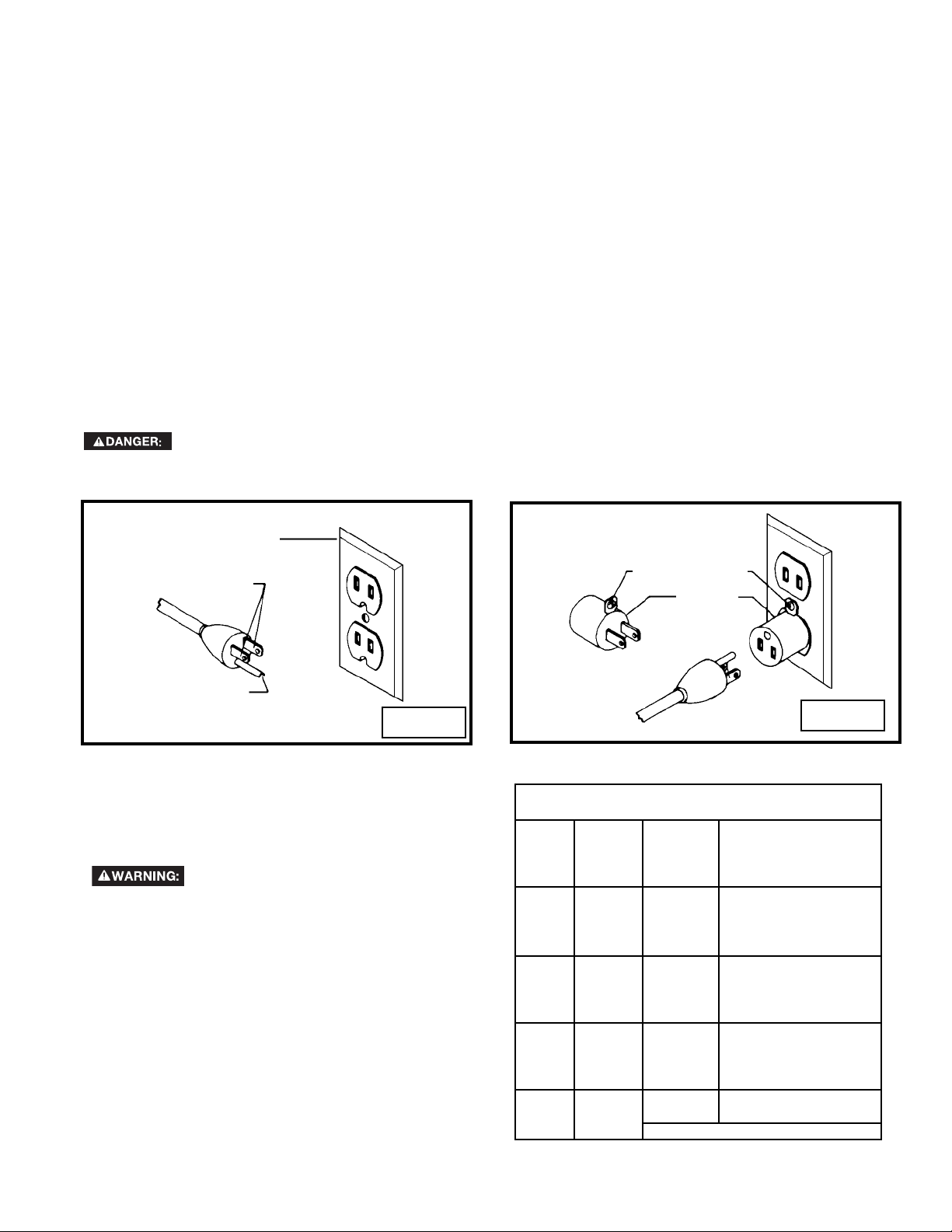
1. All grounded, cord-connected machines:
In the event of a malfunction or breakdown, grounding provides a path of least resistance for electric current to
reduce the risk of electric shock. This machine is equipped with an electric cord having an equipment-grounding
conductor and a grounding plug. The plug must be plugged into a matching outlet that is properly installed and
grounded in accordance with all local codes and ordinances.
Do not modify the plug provided - if it will not fit the outlet, have the proper outlet installed by a qualified electrician.
Improper connection of the equipment-grounding conductor can result in risk of electric shock. The conductor with
insulation having an outer surface that is green with or without yellow stripes is the equipment-grounding conductor.
If repair or replacement of the electric cord or plug is necessary, do not connect the equipment-grounding conductor
to a live terminal.
Check with a qualified electrician or service personnel if the grounding instructions are not completely understood,
or if in doubt as to whether the machine is properly grounded.
Use only 3-wire extension cords that have 3-prong grounding type plugs and matching 3-conductor receptacles that
accept the machine’s plug, as shown in Fig. A.
Repair or replace damaged or worn cord immediately.
2. Grounded, cord-connected machines intended for use on a supply circuit having a nominal rating less than
150 volts:
If the machine is intended for use on a circuit that has an outlet that looks like the one illustrated in Fig. A, the
machine will have a grounding plug that looks like the plug illustrated in Fig. A. A temporary adapter, which looks like
the adapter illustrated in Fig. B may be used to connect this plug to a matching 2-conductor receptacle as shown
in Fig. B, if a properly grounded outlet is not available. The temporary adapter should be used only until a properly
grounded outlet can be installed by a qualified electrician. The green-colored rigid ear, lug, and the like, extending
from the adapter must be connected to a permanent ground such as a properly grounded outlet box. Whenever the
adapter is used, it must be held in place with a metal screw.
NOTE: In Canada, the use of a temporary adapter is not permitted by the Canadian Electric Code.
In all cases, make certain that the receptacle in question is properly grounded. If you are not sure,
have a qualified electrician check the receptacle.
GROUNDED OUTLET BOX
CURRENT
CARRYING
PRONGS
GROUNDING BLADE
IS LONGEST OF THE 3 BLADES
Fig. A
EXTENSION CORDS
Use proper extension cords. Make
sure your extension cord is in good condition and
is a 3-wire extension cord which has a 3-prong
grounding type plug and matching receptacle which
will accept the machine’s plug. When using an
extension cord, be sure to use one heavy enough to
carry the current of the machine. An undersized cord
will cause a drop in line voltage, resulting in loss of
power and overheating. Fig. C shows the correct
gauge to use depending on the cord length. If in
doubt, use the next heavier gauge. The smaller the
gauge number, the heavier the cord.
GROUNDING MEANS
ADAPTER
MINIMUM GAUGE EXTENSION CORD
RECOMMENDED SIZES FOR USE WITH STATIONARY ELECTRIC MACHINES
Total
Ampere
rating Volts
0-6 120
0-6 120 25-50 16 AWG
0-6 120 50-100 16 AWG
0-6 120 100-150 14 AWG
6-10 120
6-10 120 25-50 16 AWG
6-10 120 50-100 14 AWG
6-10 120 100-150 12 AWG
10-12 120
10-12 120 25-50 16 AWG
10-12 120 50-100 14 AWG
10-12 120 100-150 12 AWG
12-16 120
12-16 120 25-50 12 AWG
12-16 120
length of
cord in
feet
up to
25 18 AWG
up to
25 18 AWG
up to
25 16 AWG
up to
25 14 AWG
GREATER THAN 50 FEET NOT RECOMMENDED
Gauge of
extension cord
Fig. B
Fig. C
5
Page 6
FUNCTIONAL DESCRIPTION
FOREWORD
The DELTA Model 22-590 is a 13" (330 mm) Portable Planer that has a cutting capacity of 13" (330mm) wide, 6" (152mm)
thick and 1/8" (3.2 mm) deep. This machine has a powerful 15 amp 120 volt motor with a three-knife cutterhead.
NOTICE: The photo on the manual cover illustrates the current production model. All other illustrations contained in
the manual are representative only and may not depict the actual labeling or accessories included. These are intended
to illustrate technique only.
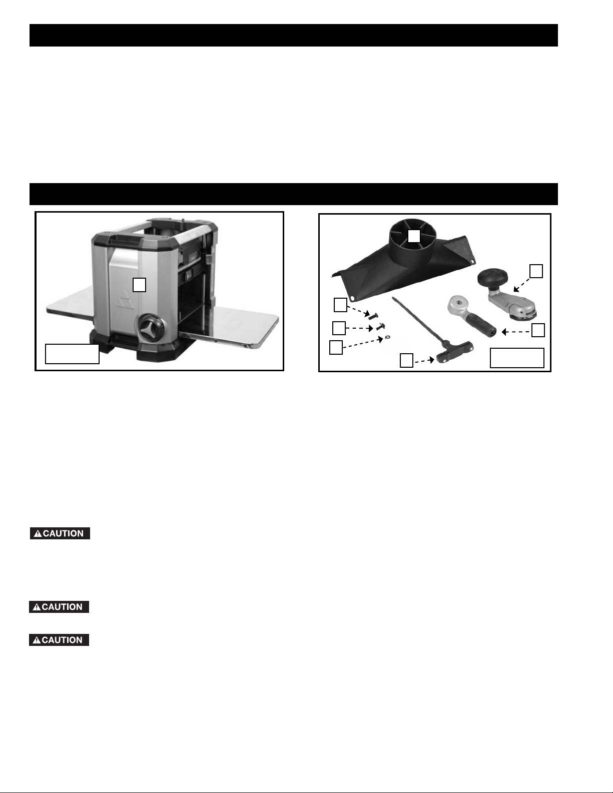
CARTON CONTENTS
2
3
1
6
Fig. 1A
1. Planer
2. Dust Collection Attachment
3. Cutterhead Adjusting Handle
4. Cutterhead Lock Handle
5. Cutterhead Wrench and Handle Combination
7
8
5
6. M6 Star Socket Head Screw
7. M6 Star Socket Head Screw and Washer
8. 6 mm Washer
Fig. 1B
4
UNPACKING AND CLEANING
This machine weighs about 75 pounds. Use a helper to lift or move it.
Carefully unpack the machine and all loose items from the shipping container. Peel protective film from the table surface.
Figures 1A and 1B illustrate the planer and all loose items supplied with your machine. Refer to the section of this
manual entitled “REPLACING KNIVES” to remove the cutterhead guard. Remove the rust-preventative oil from
unpainted surfaces using a soft cloth moistened with mineral spirits, paint thinner or denatured alcohol.
Do not use highly volatile solvents such as gasoline, naphtha, acetone or lacquer thinner for cleaning your machine.
After cleaning, cover the unpainted surfaces with a good quality household floor paste wax.
Take care when you clean the cutterhead. The knives in the cutterhead are very sharp. After cleaning the
cutterhead, replace the cutterhead guard.
6
Page 7
ASSEMBLY
To reduce the risk of injury, turn unit off and disconnect it from power source before installing and
removing accessories, before adjusting or when making repairs. An accidental start-up can cause injury.
ASSEMBLY TOOLS REQUIRED
Cutterhead Wrench (Supplied)
ASSEMBLY TIME ESTIMATE
Approximately 1/2 hour
HOW TO PREPARE FOR DUST MANAGEMENT
You have two options for dust management. The rst is the dust de ector and the second is the dust collection attachment to attach your machine to a dust collector.
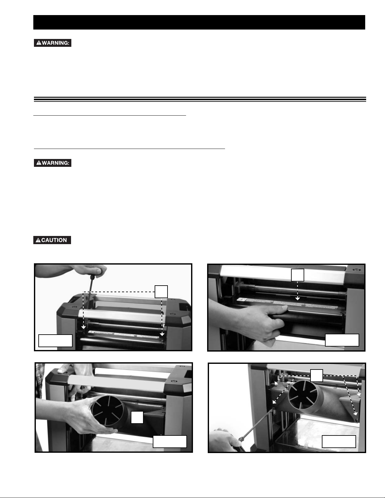
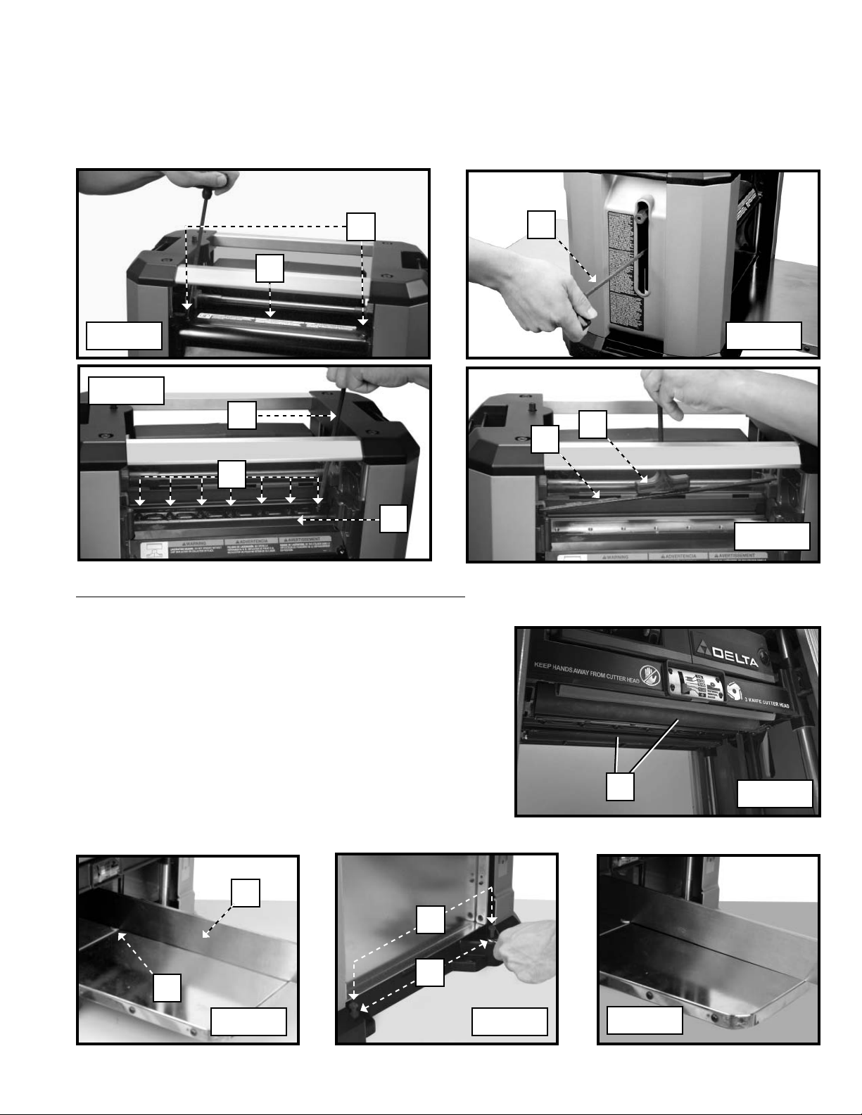
HOW TO INSTALL THE DUST COLLECTION ATTACHMENT
Disconnect the machine from the power source.
1. Remove the two screws (A) Fig. 1C that secure the dust deflector.
2. Remove the dust deflector (B) Fig. 2.
3. Place the dust collection attachment (C) Fig. 3 in the slots provided.
4. Attach the dust collection attachment with the four M6 star socket head screws (D) Fig. 4. Two of these screws were
removed in STEP 1. Tighten all fasteners securely.
5. Reverse the procedure for installing the dust deflector. Install the dust deflector with the label up and curved lip
pointing down.
When using the dust collection attachment, do not operate the unit without a hose connected and a dust
collector in operation.
Fig. 1C
B
A
Fig. 2
D
C
Fig. 4Fig. 3
7
Page 8
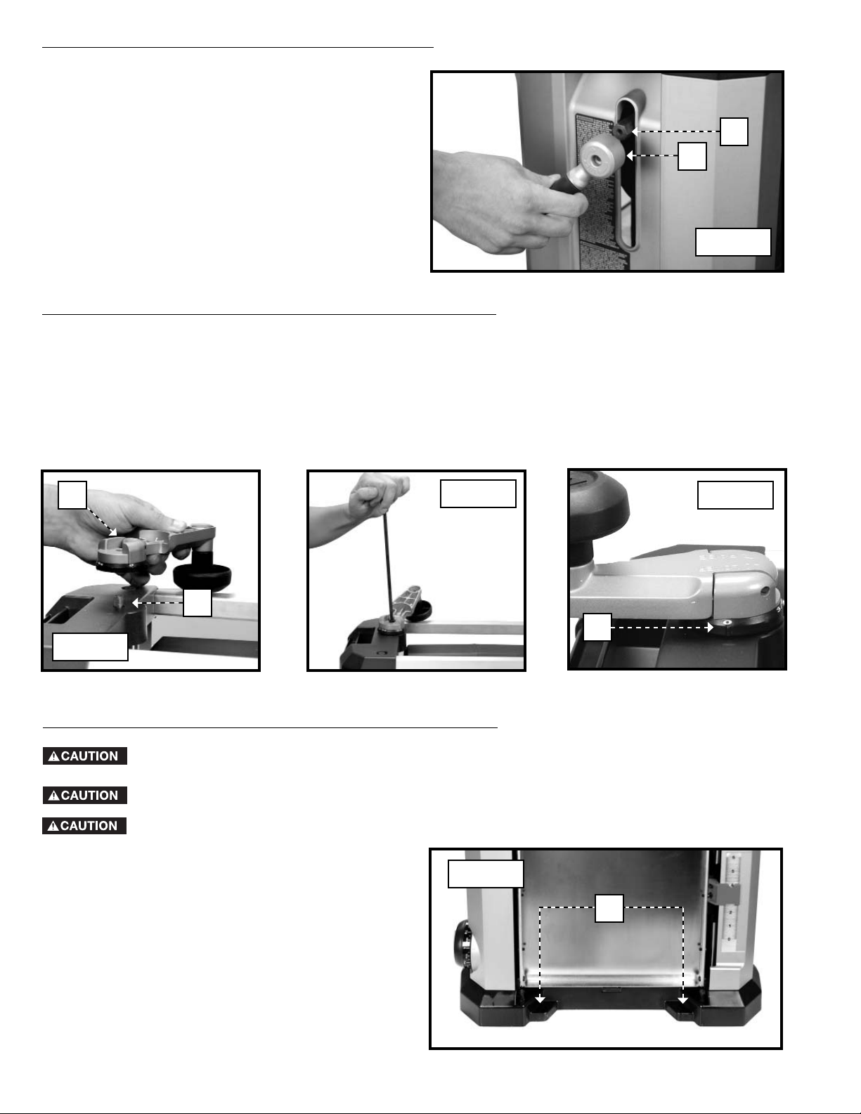
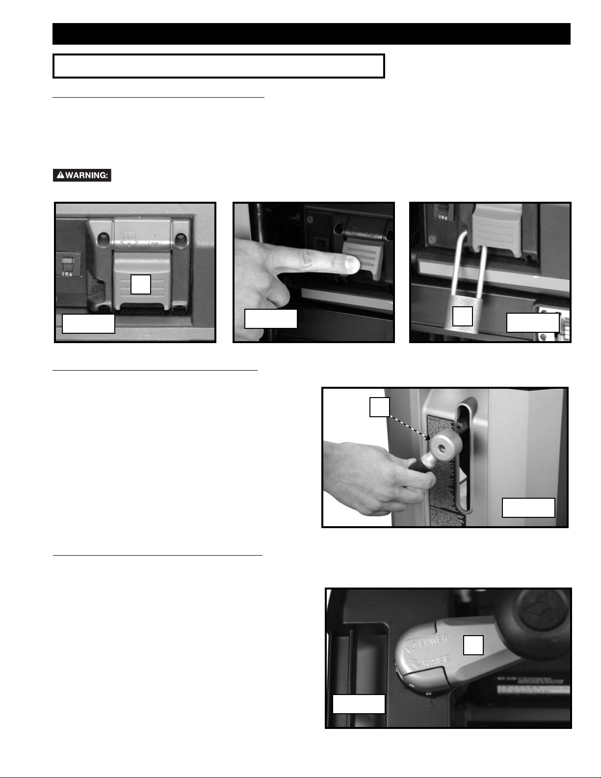
HOW TO ATTACH THE CUTTERHEAD LOCK HANDLE
Use the supplied wrench to attach the cutterhead lock
handle (A) Fig. 5 to the shaft (B) with the M6 x 20mm star
socket head screw and lockwasher.
B
A
Fig. 5
HOW TO ATTACH THE CUTTERHEAD ADJUSTMENT HANDLE
1. Attach the cutterhead adjustment handle (A) Fig. 6 to the shaft (B), with the flat on the shaft engaged with the flat in
the handle.
2. Fasten the cutterhead adjustment handle to the shaft using the M6 x 20mm star socket head screw and
lockwasher with the supplied cutterhead wrench (Fig. 7).
NOTE: The cutterhead adjustment handle is supplied with markings (C) Fig. 8 to make your cuts accurate.
A
Fig. 7
Fig. 8
B
Fig. 6
HOW TO FASTEN THE PLANER TO A SUPPORTING SURFACE
Before operation, secure the planer to the supporting surface. Four holes (two of which are shown at (A)
Fig. 9) are provided for this purpose.
Operate the planer on a flat, level surface.
Use ONLY DELTA accessory stands.
Fig. 9
Four attachment holes are provided for mounting the
planer to a stand or work surface. These holes are
located under the infeed and outfeed tables as shown in
Fig. 9.
C
A
8
Page 9
OPERATION
OPERATIONAL CONTROLS AND ADJUSTMENTS
HOW TO START AND STOP THE PLANER
To turn the planer “ON”, lift the paddle (A) Fig. 10. To turn the tool “OFF”, push the paddle down (Fig. 11).
IMPORTANT: When the machine is not in use, the switch should be locked in the “OFF” position to prevent unauthor-
ized use. Place a padlock (B) Fig. 12 with a 1/4" (6.3 mm) diameter shackle through the hole on the left side of the switch
cover and through the hole in the switch paddle. Lock the padlock.
Ensure that the lock prevents the switch from being turned on.
A
Fig. 10
Fig. 11
HOW TO USE THE CUTTERHEAD LOCK
The cutterhead lock (A) Fig. 13 helps to eliminate snipe
in the board that is being planed. Snipe can also be
eliminated by butting boards end to end and feeding
them through the planer. Long boards should always be
supported, when feeding them through the planer to help
eliminate snipe.
HOW TO ADJUST THE HEAD ASSEMBLY
A
B
Fig. 12
Fig. 13
The head assembly contains the cutterhead, feed
rollers, chip deflector and motor. Raising and lowering
the head assembly controls the depth of cut. To adjust
the head assembly, rotate the cutterhead lock handle
(A) Fig. 13 counterclockwise to unlock the cutterhead.
Turn the cutterhead adjusting handle clockwise to raise
or counter-clockwise to lower the cutterhead. One
revolution of handle (A) Fig. 14 will move the cutterhead
up or down 1/16" (1.6 mm).
A
Fig. 14
9
Page 10
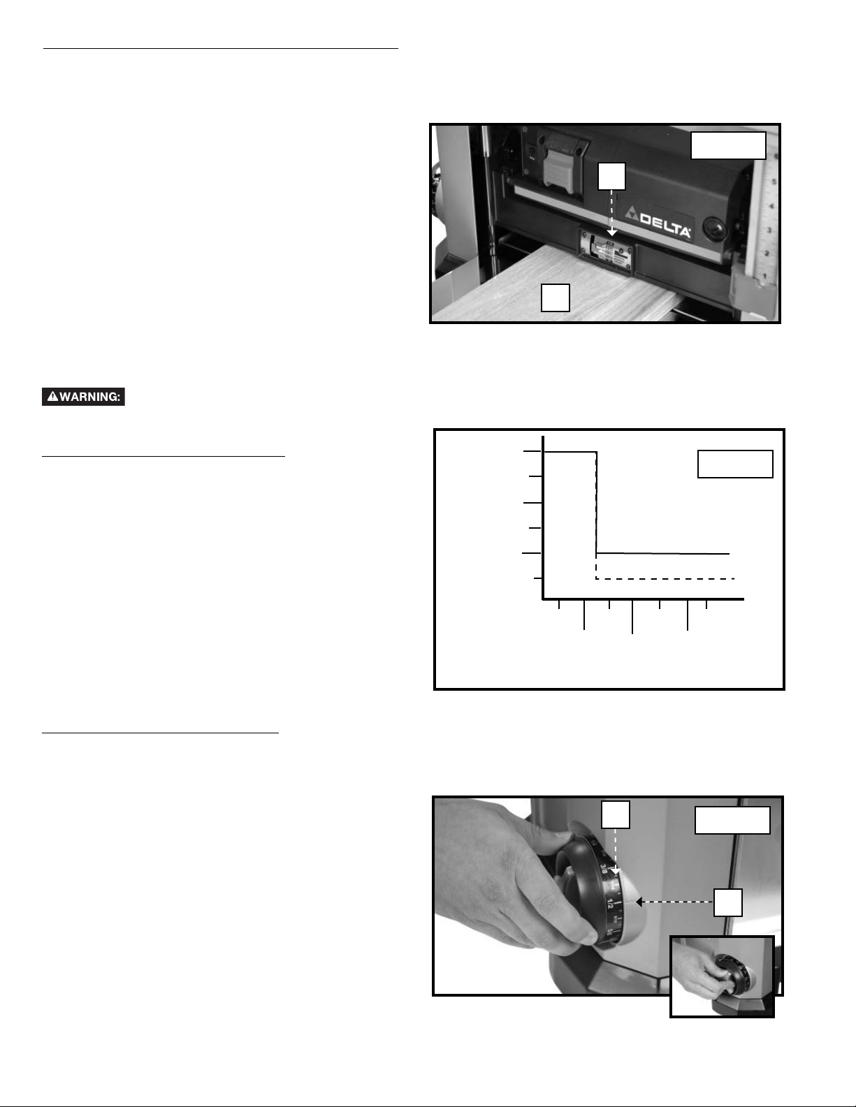
HOW TO USE THE MATERIAL REMOVAL GAUGE
Your planer is equipped with a material removal gauge (A) Fig. 15. It is used to indicate the amount of wood that will
be removed in one pass with the carriage set at its current height. The material removal gauge reads across the entire
width of the planer head.
1. Slide approximately 3" of the workpiece (B) Fig. 15
under the middle of the carriage.
2. Be sure that the workpiece is lying at against the
base of the planer. If the workpiece is inserted at an
angle, the reading may be inaccurate.
A
3. Lower the carriage on the workpiece until the material
removal bar engages the wood. You will see the red
arrow moving up the scale to indicate the amount to
be removed with the carriage at that height.
4. Adjust the carriage height until the desired depth of
cut appears on the gauge.
5. Pull the material out from under the carriage.
B
6. Turn the unit on and feed your material into the cutter
head.
NOTE: Do not exceed the recommended depth of cut for various widths of material, shown in the “RECOMMENDED
DEPTH OF CUT” section below.
Do not turn the unit “ON” with the workpiece in position.
Fig. 15
RECOMMENDED DEPTH OF CUT
NOTE: One revolution of the cutterhead adjusting
handle will move the cutterhead up or down 1/16"
(1.6 mm).
1/8"
(3.2 mm)
3/32"
(2.4 mm)
Fig. 16
You can make a 1/8" (3.2 mm) depth-of-cut in soft
woods up to 6" (152mm) wide and in hard woods up to
4" (102 mm) wide. (Fig. 16)
For 6" (152 mm) through 13" (330 mm) wide soft wood,
1/16"
(1.6 mm)
SOFT WOOD
HARD WOOD
use a maximum depth-of-cut of 1/16" (1.6 mm). For 6"
(152 mm) through 13" (330 mm) wide hard wood, use a
maximum depth-of-cut of 3/64" (1.2 mm) (Fig. 16).
IMPORTANT: A shallow depth-of-cut will produce a
better finish.
RECOMMENDED DEPTH OF CUT
2"
(51 mm)
(152 mm)
4"
(102 mm)
6"
(203 mm)
7"
(178 mm)
WIDTH OF STOCK
8"
(229 mm)
10"
(254 mm)
9"
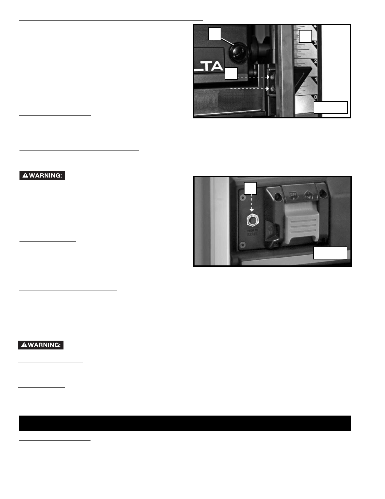
HOW TO USE THE DEPTH STOP
Your planer is equipped with a depth stop (A) Fig. 17 for repetitive planing. Any thickness between 1/8" and 1-1/4" can
be selected using the scale on the depth stop. Detents are provided at 1/8", 1/4", 1/2", 3/4", 1", and 1-1/4".
To set the minimum depth to which the carriage can travel with the depth stop:
1. Check to see that the carriage is set above 1-1/4"
before trying to set the depth stop.
2. Turn the dial on the front left of the planer until the
desired thickness setting aligns with the indicator line
(B) Fig. 17.
3. Lock the gauge in place by turning the wheel on the
inside of the gauge (Inset – Fig. 17).
4. Plane the workpiece at desired increments until the
correct nal thickness is achieved.
NOTE: Do not use force to lower the carriage below the
level that the depth stop indicates. Permanent damage to
the height adjustment system on your planer will result.
A
Fig. 17
B
10
Page 11
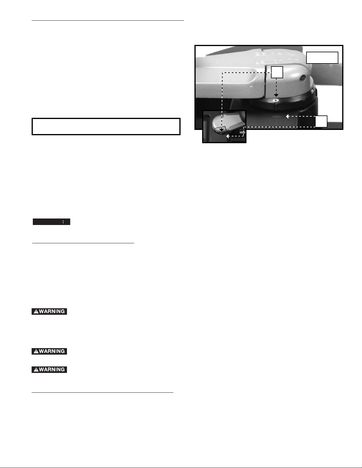
HOW TO USE THE ADJUSTABLE INDEXING RING
The cutterhead adjusting handle has an adjustment ring (A) Fig. 18. To use the adjustment ring to make fine adjustments:
1. Measure the thickness of a planed board.
2. Set the zero position of the ring (A) Fig. 18 to align with
the arrow (B).
3. Rotate the handle to the desired depth of cut, as
indicated on the ring. Each indicator on the ring is
equivalent to 1/128" (.2 mm) for making minute cuts.
4. Plane the workpiece.
A
Fig. 18
B
MACHINE USE
Follow these few steps to achieve the best results.
1. True One Face – Feed one face of the board over a jointer, making thin cuts with each pass, until the entire surface
is flat.
2. Plane to Thickness – Place the side you just surfaced in STEP 1 face down and feed the board through the planer,
plane until this side is flat. Then plane both sides of the board until you are satisfied with the thickness, making
thin cuts, alternating sides with each pass. If, during the planing operation, you notice the board twisting, warping
or bowing, repeat STEP 1 and true one face.
3. When planing long stock, provide additional support to the infeed and outfeed end of the workpiece.
4. Always engage the cutterhead lock before planing. Plane with the grain only, and keep table clean. Occasionally, wax
the table surface to reduce friction.
5. Cross-cut the workpiece to its final length.
NOTICE
knives.
Feed the wood through the planer at different places on the table to help eliminate uneven wear of the
PROPER PLANING TECHNIQUES
1. Lower the carriage to the desired height for your rst pass.
2. Turn the unit on and feed the material into the feed rollers.
3. Examine the nished cut and adjust the carriage to the appropriate height for your next pass.
4. Feed workpieces through alternating areas of the planer for even blade wear – not just through the center of the
machine. One way to do this is to start with the workpiece on the left in one pass, in the middle on the next and on
the right side for third pass – and then repeat.
NOTE: Flip the board back and forth between each pass.
Do not turn the unit on with the workpiece inserted under carriage. Wait until the roller and cutterhead are
up to full speed before feeding your material into the machine.
For best results, plane both sides of the workpiece to reach desired thickness. For example, if you need to remove 1/8"
from your workpiece, remove 1/16" from each side. This not only allows the workpiece to dry with an even moisture
content, it also produces ner cuts.
Plane only wood that is free from foreign objects, with no loose knots and as few tight knots as possible.
Do not plane wood that is severely warped, twisted, knotted or bowed.
Do not place your body between the rear of the planer and a stationary object while material is feeding.
Serious injury could result.
MINIMUM/MAXIMUM WIDTH/HEIGHT/DEPTH
NOTE: Always plane in the direction of the grain. Support the workpiece adequately at all times. Planing material less
than 3/4" wide is not recommended. If you must plane narrow material, group several pieces together and plane them as
one wide workpiece whenever possible. The maximum depth of cut your planer can take in one pass is 1/8" (on material
less than 6” wide). Never attempt to modify your planer to take a deeper cut. Follow the recommended depth/width of
cut guidelines shown in Fig. 16 for best results.
11
Page 12

SNIPE
Snipe is a depression made when an unsupported end of your material drops toward the oor, causing the opposite
end to lift up into the cutter head.
TO AVOID SNIPE
Feed the workpiece into the planer so it is level and remains at against the base at all times.
Keep the workpiece level throughout planing operation by receiving or “catching” it from the rear of the planer. If you are
planing material that is especially long, the use of additional material support is recommended.
TWISTED, CUPPED AND BOWED WOOD
If both sides of your material are very rough or if the material is cupped, bowed or twisted, your planer may not produce
the desired result. Ideally, you should have at least one level face/surface on your material before you plane. Your thickness
planer will work best with material that has been run through a jointer to produce one at surface. If you do not have at
least one at surface or a jointer, see the following recommendations.
TO PLANE TWISTED WOOD
Twisted wood may jam your planer. If a jam occurs, turn the power “OFF”, disconnect the power
supply and raise the carriage to release the workpiece from the cutter.
If your material is only slightly twisted, plane both sides alternating from one to the other until the desired thickness is
reached.
TO PLANE CUPPED WOOD
To obtain the best possible results with cupped wood, rip the material down the middle and plane it as two separate
pieces. Ripping the material reduces the severity of the cup and allows the machine to deliver better results. Understand
that you will have to remove more material on cupped wood to achieve the desired thickness than you would on a normal
board. If ripping the material is not an option, plane one side of the material until at, then plane the opposite side until it
is also at.
NOTE: Do not ip the board back and forth between each pass as recommended by the general planing directions.
TO PLANE BOWED WOOD
The feed rollers and cutter head in your planer will push the bow out of the material as it feeds. However, when the material exits the planer, the pressure of the rollers and cutterhead will release allowing the wood to spring back into a bowed
formation. To properly remove the bow, use a jointer.
TROUBLESHOOTING
For assistance with your machine, visit our website at www.deltaportercable.com for a list of service centers or
call the DELTA Machinery help line at 1-800-223-7278 (In Canada call 1-800-463-3582).
MAINTENANCE
To reduce the risk of injury, turn unit off and disconnect it from power source before installing and remov-
ing accessories, before adjusting or when making repairs. An accidental start-up can cause injury.
HOW TO CHECK, ADJUST, CLEAN AND REPLACE KNIVES
Wear gloves when you remove the knives for sharpening or replacement. The knives in this planer
are very sharp.
Disconnect the machine from the power source.
The knives are sharp. Be careful when removing, handling, or installing knives.
The knives supplied with your planer are double edged and reversible so that you can turn the knives end-for-end when
one edge becomes dull or chipped. To change the knives:
1. Raise the head assembly (B) Fig. 19 to 4" (102 mm) on the “Scale and Pointer”.
2. Remove the screws (A) Fig. 19. Pull the chip deflector or dust collection attachment – whichever is installed – (B)
straight out.
3. Insert the supplied wrench (C) Fig. 20 into the hex hole. Rotate the cutterhead until the cutterhead lock engages.
4. Remove the seven screws (E) Fig. 21 and use magnetic end of the wrench to remove the hold-down bar (F).
5. Place the magnetized end of the wrench (G) Fig. 22 at the center of the knife. Lift the wrench until the knife
(H) separates from the pins. Remove the knife.
6. Repeat steps 3 through 5 to remove the other two knives. Press down the cutterhead lock release and use the
supplied wrench (C) Fig. 20 to rotate the cutterhead lock until the lock engages and the next knife is in position to
be removed.
7. IMPORTANT: After removing all knives from cutterhead, carefully set them aside. Using a cloth rag and isopropyl
alcohol, clean the cutterhead, knives and hold-down bars free of gum, tar and pitch residue. Take special care
to clean the cutterhead under the knife area and the cutterhead radius in front of the knife area. Doing this will
increase the life of your planer.
12
Page 13
8. Take this time also to clean the rollers (I) Fig. 22A.
9. Your unit is equipped with double-edged knives. If the second edge of the knife has not been used, rotate the
knife 180 degrees and replace on the cutterhead. Replace the knives if both sides have been used.
10. Attach the hold-down bar (F) Fig. 21 that you removed in STEP 4. Tighten all fasteners securely.
11. Depress the cutterhead lock release and rotate the cutterhead to the next empty position until the cutterhead lock
engages.
12. Repeat steps 9 through 11 to replace the other knives.
13. Reattach the cutterhead guard or dust collection attachment.
A
B
Fig. 19
Fig. 21
D
E
F
HOW TO ADJUST THE INFEED AND OUTFEED TABLES
Your unit has been factory set to eliminate snipe. If your unit loses
its adjustment and causes snipe, you can adjust the infeed and
outfeed tables to minimize this condition.
1. Place a dime (A) Fig. 23A at each end of the platen (infeed and
outfeed).
2. Place a straight edge (B) across the two dimes. Extend the
straight edge past the leading edge of the infeed and trailing
edge of the outfeed tables.
3. If your tables are properly adjusted, the straight edge will touch
both of the dimes and the edges of the tables (Fig. 23C).
4. If your table needs adjustment, loosen the locknuts (A) Fig. 23B
on the table height-adjustment screws (B). Adjust the screws
up or down to achieve the desired table height.
5. Make sure that both height-adjustment screws contact the
bottom of the table after adjustment.
C
H
G
Fig. 20
Fig. 22
I
Fig. 22A
A
B
B
A
Fig. 23A Fig. 23B
13
Fig. 23C
Page 14
HOW TO CALIBRATE THE DEPTH ADJUSTMENT SCALE
The depth adjustment scale (A) Fig. 23D on your planer is
set at the factory. However, with extended use, the depth
adjustment scale could show an incorrect measurement. To
check the depth adjustment scale, plane a piece of scrap
wood, noting the measurement on the depth adjustment
scale. Measure the nished thickness of the workpiece. If
the thickness of the workpiece does not match the reading
on the depth adjustment scale, loosen the two screws (B)
on the red indicator. Adjust the pointer up or down until its
reading matches the nished thickness of the workpiece.
Securely re-tighten the screws.
BASE MAINTENANCE
Keep the table clean and free from oil, grease, and pitch.
Treat the table with paste wax to help maintain its smooth
nish.
C
A
B
Fig. 23D
CIRCUIT BREAKER RESET BUTTON
Your planer is equipped with an 18 amp circuit breaker. If your planer becomes overloaded and stops operating, turn off
the planer, let the unit sit for 2 minutes and press the reset button (A) Fig. 24 before you resume working.
To prevent the planer from starting unexpectedly if power is interrupted by a circuit
breaker trip, make sure the switch is in the "OFF" position before restoring power.
NOTE: Circuit breaker overload is often the result of dull
knives. Change your knives on a regular basis to avoid
tripping your breaker. Check your knives before re-setting the circuit breaker and continuing to plane.
A
BRUSH CHANGE
Your planer is equipped with brush caps (C) Fig. 23D that
are external to the motor. If your brushes need to be replaced, begin by acquiring a new set from a DELTA Machinery service center or a dealer authorized to service
DELTA products. Use only identical DELTA brushes.
Fig. 24
REPLACING THE DRIVE BELT
Drive belts are available at extra cost at DELTA authorized service centers. Replacement of the drive belt should be
performed by quali ed service personnel.
KEEP MACHINE CLEAN
Periodically blow out all air passages with dry compressed air. All plastic parts should be cleaned with a soft damp cloth.
NEVER use solvents to clean plastic parts. They could possibly dissolve or otherwise damage the material.
Wear certified safety equipment for eye, hearing and respiratory protection while using compressed air.
FAILURE TO START
Should your machine fail to start, check to make sure the prongs on the cord plug are making good contact in the
outlet. Also, check for blown fuses or open circuit breakers in the line.
LUBRICATION
Apply household floor paste wax to the machine table, extension table or other work surface weekly. Or use a commercially
available protective product designed for this purpose. Follow the manufacturer’s instructions for use and safety.
SERVICE
REPLACEMENT PARTS
Use only identical replacement parts. For a parts list or to order parts, visit our website at
You can also order parts from your nearest factory-owned branch, or by calling our Customer Care Center at 1-800-223-7278 to
receive personalized support from highly-trained technicians.
14
www.deltaportercableservicenet.com.
Page 15
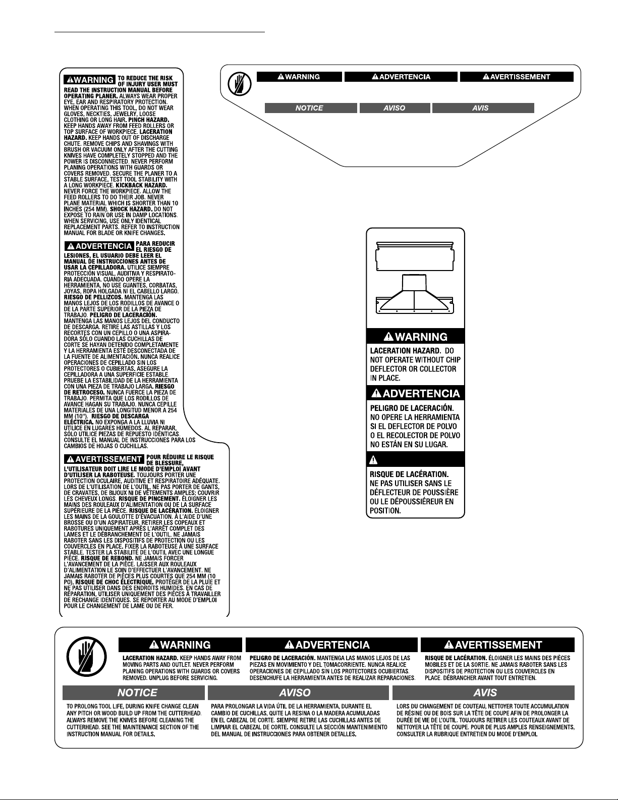
FREE WARNING LABEL REPLACEMENT
If your warning labels become illegible or are missing, call
1-800-223-7278
for a free replacement.
LACERATION HAZARD. KEEP HANDS AWAY FROM
MOVING PARTS AND OUTLET. NEVER PERFORM
PLANING OPERATIONS WITH GUARDS OR COVERS
REMOVED. UNPLUG BEFORE SERVICING.
TO PROLONG TOOL LIFE, DURING KNIFE CHANGE
CLEAN ANY PITCH OR WOOD BUILD UP FROM
THE CUTTERHEAD. ALWAYS REMOVE THE
KNIVES BEFORE CLEANING THE
CUTTERHEAD. SEE THE
MAINTENANCE SECTION
OF THE INSTRUCTION
MANUAL FOR
PELIGRO DE LACERACIÓN. MANTENGA LAS MANOS LEJOS DE LAS
PIEZAS EN MOVIMIENTO Y DEL TOMACORRIENTE. NUNCA REALICE
OPERACIONES DE CEPILLADO SIN LOS PROTECTORES OCUBIERTAS.
DESENCHUFE LA HERRAMIENTA ANTES DE REALIZAR REPARACIONES.
PARA PROLONGAR LA VIDA ÚTIL DE LA
HERRAMIENTA, DURANTE EL CAMBIO DE
CUCHILLAS, QUITE LA RESINA O LA MADERA
ACUMULADAS EN EL CABEZAL DE CORTE.
SIEMPRE RETIRE LAS CUCHILLAS ANTES DE
LIMPIAR EL CABEZAL DE CORTE. CONSULTE
LA SECCIÓN MANTENIMIENTO DEL MANUAL
DE INSTRUCCIONES PARA OBTENER
DETALLES.
DETAILS.
RISQUE DE LACÉRATION. ÉLOIGNER LES MAINS DES PIÈCES MOBILES
ET DE LA SORTIE. NE JAMAIS RABOTER SANS LES DISPOSITIFS
DE PROTECTION OU LES COUVERCLES EN PLACE. DÉBRANCHER
AVANT TOUT ENTRETIEN.
LORS DU CHANGEMENT DE COUTEAU, NETTOYER TOUTE
ACCUMULATION DE RÉSINE OU DE BOIS SUR LA TÊTE DE
COUPE AFIN DE PROLONGER LA DURÉE DE VIE DE
L’OUTIL. TOUJOURS RETIRER LES COUTEAUX
AVANT DE NETTOYER LA TÊTE DE COUPE.
POUR DE PLUS AMPLES
RENSEIGNEMENTS, CONSULTER
LA RUBRIQUE ENTRETIEN
DU MODE D’EMPLOI.
AVERTISSMENT
15
Page 16

SERVICE AND REPAIRS
All quality tools will eventually require servicing and/or replacement of parts. For information about DELTA Machinery, its
factory-owned branches, or an Authorized Warranty Service Center, visit our website at www.deltaportercable.com or call our
Customer Care Center at 1-800-223-7278. All repairs made by our service centers are fully guaranteed against defective material
and workmanship. We cannot guarantee repairs made or attempted by others.
You can also write to us for information at DELTA Machinery, 4825 Highway 45 North, Jackson, Tennessee 38305 - Attention:
Product Service. Be sure to include all of the information shown on the nameplate of your tool (model number, type, serial number,
etc.)
ACCESSORIES
Since accessories other than those offered by DELTA have not been tested with this product,
use of such accessories could be hazardous. For safest operation, only DELTA recommended accessories
should be used with this product.
A complete line of accessories is available from your DELTA Supplier, Porter-Cable•DELTA Factory Service Centers, and
DELTA Authorized Service Stations. Please visit our Web site www.deltaportercable.com for a catalog or for the name
of your nearest supplier.
WARRANTY
To register your tool for warranty service visit our website at www.deltaportercable.com.
Five Year Limited New Product Warranty
DELTA will repair or replace, at its expense and at its option, any new DELTA machine, machine part, or machine accessory which in normal
use has proven to be defective in workmanship or material, provided that the customer returns the product prepaid to a DELTA factory service
center or authorized service station with proof of purchase of the product within five years and provides DELTA with reasonable opportunity
to verify the alleged defect by inspection. For all refurbished DELTA product, the warranty period is 180 days. DELTA will not be responsible
for any asserted defect which has resulted from normal wear, misuse, abuse or repair or alteration made or specifically authorized by anyone
other than an authorized DELTA service facility or representative. Under no circumstances will DELTA be liable for incidental or consequential
damages resulting from defective products. Some states do not allow the exclusion or limitation of incidental or consequential damages, so
the above limitation or exclusion may not apply to you. This warranty is DELTA’s sole warranty and sets forth the customer’s exclusive remedy,
with respect to defective products; all other warranties, express or implied, whether of merchantability, fitness for purpose, or otherwise, are
expressly disclaimed by DELTA. For further detail of warranty coverage and warranty repair information, visit www.deltaportercable.com or call
(888) 848-5175. This warranty gives you specific legal rights and you may have other rights which vary in certain states or provinces.
LATIN AMERICA: This warranty does not apply to products sold in Latin America. For products sold in Latin America,
see country specific warranty information contained in the packaging, call the local company or see website for warranty
information.
16
Page 17

LES INSTRUCTIONS IMPORTANTES DE SURETE
quel outil ou n'importe quel équipement. En utilisant les outils ou l'équipement, les précautions de
sûreté fondamentales toujours devraient être suivies pour réduire le risque de blessure personnelle.
L'opération déplacée, l'entretien ou la modification d'outils ou d'équipement ont pour résultat la
blessure sérieux et les dommages de propriété. Il y a de certaines applications pour lequel outils et l'équipement
sont conçus. La DELTA Machinery recommande avec force que ce produit n'ait pas modifié et/ou utilisé pour
l'application autrement que pour lequel il a été conçu.
Si vous avez n'importe quelles questions relatives à son application n'utilisent pas le produit jusqu'à ce que vous
avez écrit DELTA Machinery et nous vous avons conseillé. La forme en ligne de contact à www.deltaportercable.com
Courrier Postal: Technical Service Manager, DELTA Machinery, 4825 Highway 45 North, Jackson, TN 38305.
125 Mural St. Suite 300, Richmond Hill, ON, L4B 1M4.
Information en ce qui concerne l'opération sûre et correcte de cet outil est disponible des sources suivantes:
• Power Tool Institute, 1300 Sumner Avenue, Cleveland, OH 44115-2851 ou en ligne www.powertoolinstitute.com
• National Safety Council, 1121 Spring Lake Drive, Itasca, IL 60143-3201
• American National Standards Institute, 25 West 43rd Street, 4 floor, New York, NY 10036 www.ansi.org - ANSI 01.1
Safety Requirements for Woodworking Machines
• U.S. Department of Labor regulations www.osha.gov
Lire toutes instructions d'avertissements et opération avant d'utiliser n'importe
Dans Canada,
CONSERVER CES DIRECTIVES.
MESURES DE SÉCURITÉ – DÉFINITIONS
Ce guide contient des renseignements importants que vous deviez bien saisir. Cette information porte sur VOTRE
SÉCURITÉ et sur LA PRÉVENTION DE PROBLÈMES D’ÉQUIPEMENT. Afin de vous aider à identifier cette information,
nous avons utilisé les symboles ci-dessous.
indique une situation dangereuse imminente qui, si elle n’est pas évitée, causera la mort ou des
blessures graves.
indique une situation potentiellement dangereuse qui, si elle n’est pas évitée, pourrait se solder par
un décès ou des blessures graves.
indique une situation potentiellement dangereuse qui, si elle n’est pas évitée pourrait se solder par
des blessures mineures ou modérées.
AVIS
n’est fait pour l’éviter, pourrait poser des risques de dommages matériels.
produire des poussières contenant des produits chimiques reconnus par l’État californien pour causer cancers,
malformations congénitales ou être nocifs au système reproducteur. Parmi ces produits chimiques, on retrouve:
• le plomb dans les peintures à base de plomb;
• la silice cristallisée dans les briques et le ciment ou autres articles de maçonnerie; et
• l’arsenic et le chrome dans le bois ayant subi un traitement chimique (ACC).
Le risque associé à de telles expositions varie selon la fréquence à laquelle on effectue ces travaux. Pour réduire toute
exposition à ces produits: travailler dans un endroit bien aéré, en utilisant du matériel de sécurité homologué tel un
masque antipoussières spécialement conçu pour filtrer les particules microscopiques.
indique une pratique ne posant aucun risque de dommages corporels mais qui par contre, si rien
Les scies, meules, ponceuses, perceuses ou autres outils de construction peuvent
17
Page 18

RÈGLES DE SÉCURITÉ GÉNÉRALES
L’inobservation de ces règles peut conduire à des blessures graves.
1. Pour sa sécurité personnelle, lire la notice d’utilisation,
avant de mettre la machine. En marche, et pour aussi
apprendre l’application et les limites de la machine
ainsi que les risques qui lui sont particuliers ainsi, les
possibilités d’accident et de blessures seront beaucoup
réduites.
2. Portez des dispositifs de protection des yeux et de
l'ouïe. Utilisez toujours des lunettes de sécurité. Des
lunettes ordinaires ne constituent pas des lunettes de
sécurité. Utilisez des équipements de sûreté homologués.
Les dispositifs de protection des yeux doivent être
conformes aux normes ANSI Z87.1. Les dispositifs de
protection de l'ouïe doivent être conformes aux normes
ANSI S3.19.
3. Porter une tenue appropriée. Pas de cravates, de gants,
ni de vêtements amples. Enlever montre, bagues et autres
bijoux. Rouler les manches. Les vêtements ou les bijoux
qui se trouvent pris dans les pièces mobiles peuvent
entraîner des blessures.
4. Ne pas utiliser la machine dans un environnement
dangereux. L’utilisation d’outils électriques dans des
endroits humides ou sous la pluie peut entraîner des
décharges électriques ou une électrocution. Garder la
zone de travail bien éclairée pour éviter de trébucher ou
d’exposer les doigts, les mains ou les bras à une situation
dangereuse.
5. Ne pas utiliser d’outils électriques à proximité de
liquides inflammables ou dans une atmosphère
gazeuse ou explosive. Les moteurs et interrupteurs des
outils pourraient provoquer des étincelles et enflammer
des vapeurs.
6. Garder les outils et les machines en parfait état.
Garder les outils affûtés et propres afin d’obtenir le
meilleur et le plus sûr rendement. Suivre les instructions
pour lubrifier et changer les accessoires. Les outils et les
machines mal entretenus peuvent se dégrader davantage,
et/ou entraîner des blessures.
7. Inspecter les pièces pour déceler tout dommage.
Avant d’utiliser la machine, la vérifier pour voir s’il n’y a
pas de pièces endommagées. Vérifier l’alignement des
pièces mobiles et si ces pièces ne se coincent pas, la
rupture de pièces, ou toute autre condition pouvant en
affecter le fonctionnement. Toute pièce ou protecteur
endommagé doit être réparé ou remplacé avec le DELTA
ou les pièces de rechange autorisées par usine. Les
pièces endommagées peuvent dégrader davantage la
machine et/ou entraîner des blessures.
8. Garder l’aire de travail propre. Les zones et établis
encombrés favorisent les accidents.
9. Garder les enfants et les visiteurs à distance. L’atelier
est un lieu potentiellement dangereux. Les enfants et les
visiteurs peuvent se blesser.
10. Éviter le démarrage accidentel. S’assurer que
l’interrupteur est sur « OFF » (ARRÊT) avant de brancher
le cordon. En cas de coupure de courant, placer
l’interrupteur à la position «OFF » (ARRÊT). Un démarrage
accidentel peut entraîner des blessures.
11. Utiliser les dispositifs protecteurs. Vérifier que tous les
dispositifs protecteurs sont bien en place, bien fixés et en
bon état de marche pour éviter les blessures.
12. Enlever les clés de réglage et celles de serrage avant
de mettre la machine en marche. Les outils, les chutes
et les autres débris peuvent être projetés violemment et
blesser.
13. Utiliser la bonne machine. Ne pas forcer la machine ou
l’accessoire à faire un travail pour lequel il n’a pas été
conçu. Des dommages à la machine et/ou des blessures
pourraient s’ensuivre.
14. Utiliser les accessoires recommandés. L’utilisation
d’accessoires non recommandés par DELTA peut
endommager la machine et blesser l’utilisateur.
15. Utiliser le cordon prolongateur approprié. S’assurer
que le cordon prolongateur est en bon état. Lorsqu’un
cordon prolongateur est utilisé, s’assurer que celui-ci est
d’un calibre suffisant pour l’alimentation nécessaire à la
machine. Un cordon d’un calibre insuffisant entraînera
une perte de tension d’où une perte de puissance et
surchauffe. Voir le Tableau sur Les Cordons prolongateurs
pour obtenir le calibre approprié selon la longueur du
cordon et l’ampérage de la machine. S’il y a un doute,
utiliser un cordon d’un calibre supérieur. Plus le chiffre est
petit, plus le fil est gros.
16. Fixer la pièce. Utilisez les brides ou un étau pour tenir
l'objet si pratique. La perte de commande d'un objet peut
causer des dommages.
17. Avancer la pièce dans le sens contraire à la rotation
de la lame, de la fraise ou de la surface abrasive.
L’alimentation dans l’autre sens peut entraîner une
projection violente de la pièce.
18. Ne pas forcer la machine en avançant la pièce trop vite.
Des dommages et/ou des blessures peuvent s’ensuivre.
19. Ne pas se pencher au-dessus de la machine. Une perte
de l’équilibre peut entraîner une chute sur la machine en
marche et causer des blessures.
20. Ne jamais monter sur la machine. On peut se blesser
gravement si la machine bascule ou si l’on touche
accidentellement son outil tranchant.
21. Ne jamais laisser la machine en marche sans
surveillance. Couper le courant. Ne pas quitter la
machine tant qu’elle n’est pas complètement arrêtée. Un
enfant ou un visiteur pourrait se blesser.
22. Mettre la machine à l’arrêt « OFF » et la débrancher
avant d’installer ou d’enlever des accessoires, changer
les coupeurs, d’ajuster ou de changer des montages.
En dépannant, soyez sûr de fermer le commutateur de
début en position de « OFF ». Un démarrage accidentel
peut entraîner des blessures.
23. Mettre l’atelier à l’abri des enfants au moyen de
cadenas, d’interrupteurs principaux ou en enlevant
les boutons des dispositifs de mise en marche. Le
démarrage accidentel de la machine par un enfant ou un
visiteur peut entraîner des blessures.
24. Rester vigilant, attentif, et faire preuve de bon sens. Ne
pas utiliser la machine lorsque l’on est fatigué ou sous
l’influence de drogues, d’alcool ou de médicaments. Un
instant d’inattention lors de l’utilisation d’outils électriques
peut entraîner des blessures graves.
25.
produire et disperser de la poussière ou d’autres
particules en suspension dans l’air, telles que la
sciure de bois, la poussière de silicium cristallin et
la poussière d’amiante. Dirigez les particules loin du
visage et du corps. Faites toujours fonctionner l’outil
dans un espace bien ventilé et prévoyez l’évacuation
de la poussière. Utilisez un système de dépoussiérage
chaque fois que possible. L’exposition à la poussière peut
causer des problèmes de santé graves et permanents,
respiratoires ou autres, tels que la silicose (une maladie
pulmonaire grave) et le cancer, et même le décès de la
personne affectée. Évitez de respirer de la poussière et
de rester en contact prolongé avec celle-ci. En laissant
la poussière pénétrer dans vos yeux ou votre bouche,
ou en la laissant reposer sur votre peau, vous risquez
de promouvoir l’absorption de substances toxiques.
Portez toujours des dispositifs de protection respiratoire
homologués par niosh/osha, appropriés à l’exposition à
la poussière et de taille appropriée, et lavez à l’eau et au
savon les surfaces de votre corps qui ont été exposées.
L’utilisation de cet outil peut
18
Page 19

RÈGLES SPÉCIFIQUES ADDITIONNELLES DE SÛRETÉ
L’inobservation de ces règles peut conduire à des blessures graves.
1. NE PAS FAIRE FONCTIONNER CET APPAREIL avant qu’il
ne soit entièrement assemblé et installé conformément à ces
directives. Un appareil mal assemblé peut provoquer des
blessures graves.
2. DEMANDER CONSEIL à un superviseur, instructeur, ou toute
autre personne qualifiée si l’on ne maîtrise pas parfaitement
l’utilisation de cet appareil. La connaissance est synonyme de
sécurité.
3. SUIVRE TOUS LES CODES DE CÂBLAGE et les
branchements électriques recommandés afin d’éviter les
chocs électriques ou l’électrocution.
4. MAINTENIR LES COUTEAUX AIGUISÉS et exempts de
rouille et de résine. Les couteaux émoussés ou rouillés
fonctionnent moins bien et peuvent causer un effet de
rebond.
5. NE JAMAIS DÉMARRER LA MACHINE avant de débarrasser
la table de tout objet (outils, rognures de bois, etc.). La
projection de débris peut causer des blessures graves.
6. NE JAMAIS DÉMARRER LA MACHINE si la pièce est en
contact avec le couteau. Il y aurait danger d’effet de rebond.
7. FIXER LA MACHINE À UNE SURFACE D’APPUI pour
l’empêcher de glisser, de se déplacer ou de basculer.
8. BIEN FIXER LES COUTEAUX LOGÉS DANS LE PORTE-LAME
avant de mettre l’appareil en marche. Des lames desserrées
peuvent être projetées à une vitesse élevée et causer des
blessures graves.
9. Lors du rangement ou du transport de l’appareil, NE PAS
RANGER LE CORDON D’ALIMENTATION sous le portelame.
10. ÉVITER LES OPÉRATIONS MALADROITES ET ÉVITER
D’AVOIR LES MAINS MAL PLACÉES. Un glissement soudain
de la pièce pourrait entraîner votre main vers les couteaux
11. TENIR LES BRAS, MAINS ET DOIGTS éloignés du porte-
lame, de l’orifice d’extraction des copeaux et des cylindres
d’entraînement pour éviter de profondes coupures.
12. SE TENIR LOIN DE LA ZONE DU PORTE-LAME lorsque la
machine fonctionne. Vos mains pourraient être entraînées dans
les couteaux.
13. NE PAS SE TENIR DANS LE MÊME AXE QUE LA PIÈCE. Un
effet de rebond peut causer des blessures.
14. LE PORTE-LAME DOIT ATTEINDRE SA VITESSE
MAXIMALE avant d’acheminer une pièce.
15. POUR LE RABOTAGE DE BOIS SPÉCIAL COURBÉ, placer
la partie concave de la pièce sur la table, et raboter dans le
sens du grain pour éviter tout effet de rebond.
16.
NE PAS ACHEMINER UNE PIÈCE qui est gauchie, qui présente
des nœuds ou qui comprend des objets étrangers (clous, agrafes,
etc.). Il y a risque d’effet de rebond.
17. NE PAS INSÉRER UNE PIÈCE DE FAIBLE LONGUEUR,
ÉPAISSEUR OU ÉTROITE DANS LA MACHINE. Vos mains
pourraient être entraînées sur les couteaux ou la pièce peut
être projetée à une vitesse élevée. Consulter la SECTION
« Utilisation » de ce mode d’emploi pour obtenir des détails.
18. NE PAS INSÉRER UNE PIÈCE par l’extrémité de sortie de la
machine. La pièce sera projetée du côté opposé à une vitesse
élevée.
19.
ENLEVER UNIQUEMENT LES FRISURES DE BOIS lorsque la
machine est éteinte pour éviter toute blessure grave.
20. UTILISATION PRÉVUE UNIQUEMENT POUR APLANIR LE
BOIS. Ne pas raboter des matières manufacturées.
21. SOUTENIR CORRECTEMENT LES PIÈCES LONGUES OU
LARGES. La perte de contrôle de la pièce peut provoquer de
graves blessures.
22. NE JAMAIS EFFECTUER D’OPÉRATION DE TRAÇAGE,
D’ASSEMBLAGE, ou de réglage sur la table/l’espace de
travail lorsque la machine est en marche. Cela risquerait
d’entraîner des blessures graves.
23. ÉTEINDRE LA MACHINE ET LA DÉBRANCHER. Nettoyer
la table/l’espace de travail avant de quitter la machine.
Afin d’éviter toute utilisation non autorisée, VERROUILLER
L’INTERRUPTEUR EN POSITION ARRÊT. Quelqu’un
pourrait par mégarde faire démarrer la machine et se blesser
ou blesser d’autres personnes.
24. DES INFORMATIONS SUPPLÉMENTAIRES (c.-à-d. une
vidéo sur la sécurité), sur la façon d’utiliser des outils électriques
correctement et en toute sécurité, sont offertes auprès du
Power Tool Institute, 1300 Sumner Avenue, Cleveland, OH
44115-2851, États-Unis (www.powertoolinstitute.com). Des
renseignements sont également offerts auprès du National
Safety Council, 1121 Spring Lake Drive, Itasca, IL, 601433201 É.-U. Consulter les règles de sécurité de la norme ANSI
01,1 (American National Standards Institute) concernant les
machines à travailler le bois, ainsi que la réglementation du
département du Travail des É.-U.
CONSERVER CES DIRECTIVES.
Les consulter souvent et les utiliserpour donner des directives aux autres.
RACCORDEMENTS ÉLECTRIQUES
Un circuit électrique séparé doit être utilisé pour les machines. Ce circuit doit utiliser un câble de calibre 12 au minimum et doit être protégé
par un fusible temporisé. REMARQUE : les fusibles temporisés devraient avoir l’inscription « D » au Canada et « T » aux É.-U. Si on utilise
un cordon prolongateur, ce cordon doit être à trois fils, avoir unefiche à trois broches et une prise de courant à trois cavités, mise à la terre
qui correspond à la fiche de la machine. Avant debrancher la machine, s’assurer que l’interrupteur se trouve en position « OFF » (ARRÊT)
et que le courantélectrique présente les mêmes caractéristiques que celles qui sont inscrites sur la machine. Toutes les connexions
électriquesdoivent établir un bon contact. Le fonctionnement sur une basse tension endommagera la machine.
Ne pas exposer la machine à la pluie, et ne pas l’utiliser dans des endroits humides.
SPÉCIFICATIONS DU MOTEUR
Cette machine est câblée pour un fonctionnement sur un courant alternatif de 120 volts 60 Hz. Avant de brancher la machine, s’assurer que
l’interrupteur se trouve à la position « OFF » (ARRÊT).
INSTRUCTIONS DE MISE À LA TERRE
Cette machine doit être mise à la terre pendant son emploi, afin de protéger l’utilisateur des décharges électriques.
19
Page 20

1. Toutes les machines avec cordon mis à la terre: Dans l’éventualité d’un mauvais fonctionnement ou d’une panne, la mise à
la terre fournit un trajet de moindre résistance permettant de réduire le risque de décharge électrique. Cette machine est dotée
d’un cordon électrique possédant un conducteur de mise à la terre de l’équipement ainsi que d’une fiche mise à la terre. La fiche
doit être branchée dans une prise de courant correspondante, installée de façon adéquate et mise à la terre conformément à
tous les codes et règlements locaux.
Ne pas modifier la fiche fournie – si elle ne s’adapte pas à la prise de courant, il faut faire installer une prise de courant
convenable par un électricien compétent.
Un mauvais raccordement du conducteur de mise à la terre de l’équipement peut entraîner un risque de décharge électrique. Le
conducteur possédant un isolant avec surface extérieure de couleur verte, avec ou sans rayures jaunes, est le conducteur de
mise à la terre de l’équipement. Si une réparation ou un remplacement du cordon électrique s’avère nécessaire, ne pas brancher
le conducteur de mise à la terre de l’équipement à une borne sous tension.
Consulter un électricien compétent ou le personnel de service après-vente si on ne comprend pas entièrement les instructions
de mise à la terre, ou si l’on doute que la machines oit correctement mise à la terre.
Utiliser seulement des cordons prolongateurs à trois fils dotés d’une fiche mise à la terre, à trois broches, et de prises à trois
cavités convenant à la fiche de la machine, comme l’illustre la figure A.
Réparer ou remplacer sans délai tout cordon endommagé ou usé.
2. Machines avec cordon mis à la terre prévues pour une utilisation sur une alimentation nominale inférieure à 150 volts:
Si cette machine est prévue pour être utilisée sur un circuit qui comporte une prise semblable à celle illustrée à la figure A, la
machine devra comporter une fiche mise à la terre semblable à celle illustrée à la figure A. Un adaptateur temporaire semblable à
celui illustré à la figure B, peut être utilisé pour raccorder cette fiche à une prise à deux cavités comme celle illustrée à la figure B,
si une prise correctement mise à la terre n’est pas disponible. L’adaptateur temporaire ne doit être utilisé que jusqu’au moment
où une prise correctement mise à la terre est installée par un électricien compétent. L’oreille rigide ou autre dispositif semblable
de couleur verte, sur le dessus de l’adaptateur, doit être connecté sur une mise à la terre permanente comme, par exemple une
boîte à prises correctement mise à la terre. Quand un adaptateur est utilisé, celui-ci doit être retenu en place par une vis en
métal.
REMARQUE: Au Canada, le Code canadien de l’électriciténe permet pas l’emploi d’un adaptateur temporaire.
électricien compétent de vérifier la prise.
Dans tous les cas, s’assurer quela prise en question est bien mise à la terre. Dans le doute, demander à un
BOÎTE À PRISES MISE À LA TERRE
BROCHES
CONDUCTRICES DE
COURANT
LA BROCHE DE MISE
À LA TERRE EST LA PLUS
LONGUE DES TROIS
Fig. A
CORDON DE RALLONGE
Employez les cordes
appropriées de prolongation. S’assurent votre corde
de prolongation est en bon état. En utilisant une corde
de prolongation, soyez sûr d’employer un assez lourd
pour porter le courant de la machine. Une corde trop
petite causera une baisse dans la tension secteur, ayant
pour résultat la perte de puissance et de surchauffe.
Fig. C expositions la mesure correcte à employer
selon la longueur de corde. En cas de doute, utilisez
la prochaine mesure plus lourde. Plus le nombre de
mesure est petit, plus la corde est lourde.
OREILLE DE MISE À
LA TERRE
ADAPTATEUR
Fig. B
MESUR MINIMUM DE CORDE D’EXTENSION
TAILLES RECOMMANDÉES POUR L’USAGE AVEC STATIONNAIRES ÉLECTRIQUES LES OUTILS
Longueur
Estimation
ampère Volts
0-6 120
0-6 120 25-50 16 AWG
0-6 120 50-100 16 AWG
0-6 120 100-150 14 AWG
6-10 120
6-10 120 25-50 16 AWG
6-10 120 50-100 14 AWG
6-10 120 100-150 12 AWG
10-12 120
10-12 120 25-50 16 AWG
10-12 120 50-100 14 AWG
10-12 120 100-150 12 AWG
12-16 120
12-16 120 25-50 12 AWG
12-16 120
totale de
corde en
pieds
jusqu’à
jusqu’à
jusqu’à
jusqu’à
50 PI PLUS GRANDS QUE NON RECOMMANDES
Mesure de corde d’am
d’extension
25 18 AWG
25 18 AWG
25 16 AWG
25 14 AWG
20
Fig. C
Page 21

DESCRIPTION FONCTIONNELLE
AVANT-PROPOS
Le modèle DELTA 22-590 est une raboteuse portative de 330 mm (13 po) ayant une capacité de coupe en largeur de 330 mm (13
po), en épaisseur de 152 mm (6 po) et en profondeur de 3,2 mm (1/8 po). Cet appareil est pourvu d’un puissant moteur de 15 A,
120 V et d’un porte-lame à trois couteaux.
REMARQUE : La image sur la couverture illustre le modèle de production actuel. Les autres illustrations de ce mode d’emploi ne sont
présentes qu’à titre indicatif et il est possible que les étiquettes et accessoires actuels diffèrent des caractéristiques réelles de ce modèle.
Ces illustrations ont uniquement pour but d’illustrer la technique.
CONTENUS DE BOITE
2
3
1
6
Fig. 1A
1. Raboteuse
2. Pièce pour système de dépoussiérage
3. Poignée de réglage du porte-lame
4. Poignée de verrouillage du porte-lame
5. Combinaison de clé et de poignée du
porte-lame
7
8
Fig. 1B
6. Vis à tête creuse étoilée M6 mm
7. Vis à tête creuse étoilée et rondelle M6 mm
8. Rondelle de 6 mm
4
5
DÉSEMBALLAGE ET NETTOYAGE
Cet appareil pèse environ 34 kg (75 lb). Le lever ou le transporter à deux personnes.
Désemballer soigneusement l’appareil et toutes les pièces de l’emballage d’expédition. Décoller le lm protecteur de la surface de la
table. Les gures 1A et 1B illustrent la raboteuse et toutes les pièces détachées fournies avec l’appareil. Consulter la section de ce
mode d’emploi intitulée « REMPLACEMENT DES COUTEAUX » pour enlever le dispositif de protection de la tête de coupe. Retirer
l’huile anticorrosion des surfaces non peintes à l’aide d’un chiffon doux humecté avec de l’alcool, du diluant à peinture ou de l’alcool
dénaturé.
N’utiliser pas de solvants hautement volatils tel l’essence, le naphte, l’acétone ou du diluant à laque
pour nettoyer.
Après nettoyage, couvrir les surfaces non peintes d’une cire à parquets d’usage domestique de bonne qualité.
Être prudent pour nettoyer le porte-lame. Les couteaux du porte-lame sont très tranchants. Après avoir
effectué le nettoyage du porte-lame, remettre son dispositif de protection.
21
Page 22

ASSEMBLAGE
Pour réduire le risque de blessures corporelles graves, éteindre l’outil et le débrancher avant
d’installer et de retirer tout accessoire, avant d'ajuster ou de modifier les réglages ou lors de réparations. Un démar-
rage accidentel peut provoquer des blessures.
OUTILS NÉCESSAIRES POUR L’ASSEMBLEE
Clé et de poignée (Fourni)
L'ESTIMATION DE TEMPS D'ASSEMBLEE
Approximativement 1/2 heure
PRÉPARATION POUR LA GESTION DE LA POUSSIÈRE
Il existe deux options de gestion de la poussière. La première consiste à utiliser le dé ecteur de poussière alors que la
deuxième consiste à relier la pièce pour système de dépoussiérage de l’appareil à un dépoussiéreur.
INSTALLATION DE LA PIÈCE POUR SYSTÈME DE DÉPOUSSIÉRAGE
Débranchez la machine.
1. Enlever les deux vis (A), fig. 1C, qui fixent le déflecteur de poussière.
2. Retirer le déflecteur de poussière (B), fig. 2.
3. Insérer la pièce pour système de dépoussiérage (C), fig. 3, dans les fentes disponibles.
4. Au moyen des 4 vis à tête creuse étoilée M6 (D), fig. 4, fixer la pièce pour système de dépoussiérage. Deux de ces
vis ont été retirées à l’ÉTAPE 1. Serrer solidement toutes les attaches.
5. Pour l’installation du déflecteur de poussière, inverser la procédure. Installer le déflecteur de poussière, étiquette
vers le haut et rebord courbé pointant vers le bas (fig. 1).
Lors de l’utilisation de la pièce pour système de dépoussiérage, ne pas faire fonctionner l’appareil sans
y raccorder un tuyau et un dépoussiéreur en fonctionnement.
Fig. 1C
B
A
Fig. 2
D
C
Fig. 4Fig. 3
22
Page 23

MÉTHODE DE FIXATION DE LA POIGNÉE DE VERROUILLAGE DU PORTE-LAME
Utiliser la clé fournie pour fixer la poignée de verrouillage
du porte-lame (A), fig. 5, à la tige (B) avec une vis à tête
creuse étoilée M6 x 20 mm et une rondelle de blocage.
B
A
Fig. 5
MÉTHODE DE FIXATION DE LA POIGNÉE DE RÉGLAGE DU PORTE-LAME
1. Fixer la poignée de réglage du porte-lame (A) fig. 6 à la tige (B) et s’assurer que le méplat de la tige est en prise avec le
méplat de la poignée.
2. Au moyen d’une vis à tête creuse étoilée M6 x 20 mm et d’une rondelle de blocage, assembler la poignée de réglage
du porte-lame à la tige avec la clé fournie (fig. 7).
REMARQUE : la poignée de réglage du porte-lame fournie comporte des repères (C), fig. 8, pour aplanir de façon précise.
A
Fig. 7
Fig. 8
B
Fig. 6
ASSUJETTISSEMENT DE LA RABOTEUSE À UNE SURFACE DE MAINTIEN
Avant d’utiliser l’appareil, fixer solidement la raboteuse à une surface de maintien. Quatre orifices
(deux des quatre orifices sont illustrés en (A), fig. 9), sont percés à cet effet.
Faire fonctionner la raboteuse sur une surface plane et au niveau.
Utiliser UNIQUEMENT des socles accessoires DELTA.
Fig. 9
Les quatre trous de fixation sont fournis pour assembler
la raboteuse à un socle ou une surface de travail. Ces
trous sont logés sous les tables d’alimentation et de
sortie comme indiqué à la fig. 9.
C
A
23
Page 24

FONCTIONNEMENT
L’OPERATION CONTROLE DE LE ET LES AJUSTEMENTS
DÉMARRAGE ET ARRÊT DE MACHINE
Pour mettre la raboteuse « SOUS TENSION » (ON), relever l’interrupteur à palette (A), fig. 10. Pour « ETEINDRE » (OFF)
l’appareil, l’abaisser (fig. 11).
IMPORTANT : lorsque l’appareil est inutilisé, l’interrupteur devrait être verrouillé en position d’arrêt pour empêcher toute
utilisation non autorisée. Insérer un cadenas (B), fig. 12, muni d’une anse de 6,3 mm (¼ po) de diamètre dans le trou du
côté gauche du couvercle de l’interrupteur et celui de l’interrupteur à palette. Verrouiller le cadenas.
S’assurer que le cadenas empêche bien la manipulation de l’interrupteur.
A
Fig. 10
Fig. 11
UTILISATION DU DISPOSITIF DE VERROUILLAGE DU PORTE-LAME
A
Le dispositif de verrouillage du porte-lame (A) fig. 13,
sert à éliminer les entailles produites sur la planche étant
aplanies. Les entailles peuvent aussi être éliminées en
aboutant les planches et en les acheminant ainsi dans
la raboteuse. Les planches de longue portée doivent
être soutenues au moment de les acheminer dans la
raboteuse pour aider à éliminer les entailles.
RÉGLAGE DU MODULE DE TÊTE
B
Fig. 12
Fig. 13
Le module de tête comprend les couteaux, les rouleaux
d’alimentation, le déflecteur de copeaux et le moteur.
La hausse et la baisse du module de tête permet de
régler la profondeur de coupe. Pour le régler, tourner
la poignée de verrouillage du porte-lame (A), fig. 13,
dans le sens antihoraire de manière à déverrouiller le
porte-lame. Tourner la poignée de réglage dans le sens
horaire pour hausser le porte-lame ou dans le sens
antihoraire pour le baisser. Un tour de la poignée (A), fig.
14, déplacera le porte-lame de 1,6 mm (1/16 po) vers le
haut ou le bas.
A
Fig. 14
24
Page 25

UTILISATION DU GUIDE D’ENLÈVEMENT DE MATIÈRE
La raboteuse est munie d’un guide d’enlèvement de matière (A), g. 15. Il indique la quantité de bois qui sera enlevée en un passage avec
le chariot réglé à la hauteur actuelle. Le guide d’enlèvement de matière fonctionne sur toute la largeur du module de tête de la raboteuse.
1. Glisser, dans le milieu, environ 76,2 m (3 po) de la pièce (B),
g. 15, sous le chariot.
2. S’assurer que la pièce est bien à plat contre la base de la
raboteuse. Si elle est insérée à un angle quelconque, la
lecture du guide sera imprécise.
3. Abaisser le chariot sur la pièce jusqu’à ce que la barre
d’enlèvement de matière morde dans le bois. La èche
rouge se déplacera vers le haut sur l’échelle et indiquera la
quantité de matière qui sera enlevée avec le chariot à cette
hauteur.
4. Régler la hauteur du chariot jusqu’à l’obtention de la profondeur de coupe voulue sur le guide.
5. Retirer la pièce sous le chariot.
6. Mettre l’appareil sous tension et alimenter la pièce sous le
porte-lame.
REMARQUE : ne pas excéder la profondeur de coupe recommandée pour les diverses largeurs de pièce comme indiqué sous la
rubrique « PROFONDEUR DE COUPE RECOMMANDEE » ci-dessous.
Ne pas mettre l’appareil sous tension avec une pièce engagée en position.
B
A
Fig. 15
PROFONDEUR DE COUPE RECOMMANDÉE
REMARQUE : un tour de la poignée de réglage permet de
relever ou d’abaisser le porte-lame de 1,6 mm (1/16 po).
Il est possible d’obtenir une profondeur de coupe de 3,2 mm
(1/8 po) pour les bois mous dont la largeur maximum est de
152 mm (6 po) et pour les bois durs dont la largeur maximum
est de 102 mm (4 po). (Consulter la fig. 16).
Pour les pièces de bois mous de 152 à 330 mm (6 à 13
po) de largeur, la profondeur de coupe maximum est de
1,6 mm (1/16 po). Pour les pièces de bois durs de largeurs
correspondantes, la profondeur de coupe maximum est de 1,2
mm (3/64 po) (fig. 16).
IMPORTANT : une profondeur de coupe peu profonde
produira un meilleur fini.
PROFONDEUR DE COUPE
1/8"
(3.2 mm)
3/32"
(2.4 mm)
1/16"
(1.6 mm)
RECOMMANDÉE
2"
(51 mm)
LARGEUR DE LA PIÈCE
(152 mm)
4"
(102 mm)
6"
(178 mm)
BOIS MOUS
BOIS DUR
8"
(203 mm)
7"
Fig. 16
10"
(254 mm)
9"
(229 mm)
UTILISATION DE LA BUTÉE DE PROFONDEUR
Pour le rabotage répétitif, la raboteuse est munie d’une butée de profondeur (A), g. 17. Au moyen de l’échelle de la butée de profondeur, il est possible de choisir une épaisseur entre 3,2 et 31,8 mm (1/8 et 1-1/4 po). Des crans sont prévus à 3,2 mm (1/8 po), 6,4
mm (1/4 po), 12,7 mm (1/2 po), 19 mm (3/4 po), 25,4 mm (1 po) et 31,8 mm (1-1/4 po).
Pour régler la profondeur minimum à laquelle il est possible
d’utiliser le chariot avec la butée de profondeur, procéder
comme suit :
1. Avant de régler la butée de profondeur, véri er que le chariot est au-dessus du cran de 31,8 mm (1-1/4 po).
2. Tourner la molette, logée du côté gauche avant de la raboteuse, jusqu’à ce que le paramètre d’épaisseur choisi
s’aligne avec la ligne indicatrice (B), g. 17.
3. Verrouiller le guide en position en tournant la molette logée
à l’intérieur du guide (encadré - g. 17).
4. Raboter la pièce par pas jusqu’à l’obtention de la bonne
épaisseur nale.
REMARQUE : ne pas forcer le chariot au-delà du niveau indiqué par la butée de profondeur. En effet, une telle pratique
endommagera le système de réglage de la hauteur de la raboteuse de manière durable.
A
Fig. 17
B
25
Page 26

UTILISATION DE LA BAGUE D’INDEXAGE RÉGLABLE
La poignée de réglage du porte-lame comprend une bague de réglage (A) fig. 18. Utiliser la bague de réglage pour
effectuer des réglages fins :
1. Mesurer l’épaisseur d’une planche rabotée.
2. Aligner la flèche (B), fig. 18, avec la position zéro de la
bague (A).
3. Tourner la poignée à la profondeur de coupe voulue,
A
Fig. 18
comme il est indiqué sur la bague. Chaque indicateur
de la bague équivaut à 0,2 mm (1/128 po) et permet de
pratiquer de petites coupes.
4. Raboter la pièce.
B
UTILISATION DE LA MACHINE
Respecter ces quelques étapes pour optimiser les résultats.
1. Dresser un côté – Acheminer l’une des faces de la planche sur la dégauchisseuse, retirer une mince couche à
chaque passage jusqu’à l’obtention d’une surface complète plane.
2. Raboter à épaisseur voulue – Insérer le côté dégauchit à l’ÉTAPE 1 vers le bas et acheminer la planche dans la
raboteuse. Raboter jusqu’à ce que ce côté soit plat. Raboter ensuite les deux côtés de la planche par coupes fines
en alternant les côtés jusqu’à ce que l’épaisseur désirée soit atteinte. S’il se produit un voilement, gauchissement
ou courbure de la planche durant le rabotage, reprendre l’ÉTAPE 1 et dégauchir un côté.
3. Pour le rabotage de longues pièces, fournir un soutien supplémentaire à l’entrée et à la sortie.
4. Toujours engager le verrouillage du porte-lame avant de raboter une pièce. Ne raboter que dans le fil du bois et
garder la table propre. Pour réduire la friction, cirer la surface de la table de façon périodique.
5. Couper la pièce à sa longueur finale.
AVIS
raboteuse.
Pour éviter l’usure inégale des couteaux, insérer les pièces à différents endroits sur la table de la
TECHNIQUES APPROPRIÉES DE RABOTAGE
1. Abaisser le chariot à la hauteur voulue pour le premier passage.
2. Mettre l’appareil sous tension et acheminer la pièce sur les rouleaux d’alimentation.
3. Examiner le résultat et régler la hauteur du chariot pour le prochain passage.
4. A n d’user la lame de la raboteuse de manière uniforme lors de l’acheminement des pièces, éviter d’alimenter toujours les pièces
par le centre de l’appareil. Varier le point d’entrée. Par exemple, commencer le premier passage avec la pièce à gauche, puis au
centre pour le deuxième passage et à droite pour le troisième passage. Pour poursuivre, répéter la séquence.
REMARQUE : entre chaque passage dans l’appareil, alterner les deux côtés de la pièce. Consulter le guide de dépannage pour de
plus amples renseignements.
Ne pas mettre l’appareil sous tension avec une pièce engagée sous le chariot. Avant d’acheminer la pièce
dans l’appareil, attendre que le rouleau et le porte-lame fonctionnent à plein régime.
Pour optimiser les résultats, raboter les deux côtés de la pièce pour atteindre l’épaisseur désirée. S’il faut enlever 3,2 mm (1/8 po) de
matière par exemple, enlever 1,6 mm (1/16 po) de chaque côté. Cette technique permet d’uniformiser le taux d’humidité de la pièce
et d’effectuer des coupes plus nes.
Raboter uniquement des pièces de bois exemptes de corps étrangers, sans nœuds détachés, avec un
minimum de nœuds adhérents. Ne pas raboter des pièces de bois très voilées, tordues, nouées ou bombées.
Lors de l’alimentation des pièces dans l’appareil, ne pas placer votre corps entre la raboteuse et un objet
xe. De graves blessures peuvent survenir.
LARGEUR, HAUTEUR ET PROFONDEUR MINIMUMS ET MAXIMUMS
REMARQUE : toujours raboter dans le l du bois. Appuyer la pièce correctement, à tout moment. Il n’est pas recommandé de raboter
des pièces de moins de 19 mm (3/4 po) de largeur. Dans ces cas, regrouper autant que possible plusieurs pièces et les raboter comme
s’il s’agissait d’une seule pièce plus large. La raboteuse est en mesure d’enlever une épaisseur maximum de 3,2 mm (1/8 po) en un passage (pour des pièces de moins de 152 mm [6 po] de largeur). Ne jamais modi er la raboteuse pour enlever une couche plus épaisse.
Pour optimiser les résultats, respecter la profondeur et la largeur recommandées dans les lignes directrices indiquées à la g. 16.
ENTAILLE
Une entaille est en fait un creux formé lorsqu’une extrémité non appuyée de la pièce tombe vers le sol entraînant ainsi l’autre extrémité
vers le haut, sur le porte-lame.
26
Page 27

MÉTHODE POUR ÉVITER LES ENTAILLES
Alimenter la pièce dans la raboteuse de sorte qu’elle est de niveau et qu’elle demeure bien à plat contre la base et ce, en tout temps.
Pour maintenir la pièce de niveau tout au long du rabotage, l’attraper à la sortie de la raboteuse. Si la pièce à raboter est particulièrement longue, utiliser un appui supplémentaire.
BOIS TORDU, BOMBE ET VOILE
Il est possible de ne pas obtenir le résultat souhaité si les deux côtés de la pièce sont à l’état brut ou si la pièce est bombée, voilée
ou tordue. Avant de raboter, avoir de préférence au moins un côté ou une surface de niveau. La raboteuse donnera de meilleurs résultats si la pièce est d’abord dégauchie au moyen d’une dégauchisseuse pour obtenir une surface plane. Lire les recommandations
suivantes en l’absence d’un côté plat ou d’une dégauchisseuse.
RABOTAGE D’UNE SURFACE TORDUE
Une pièce de bois tordue risque de faire coincer la raboteuse. Dans ce cas, mettre l’appareil hors
tension et le débrancher. Relever le chariot pour dégager la pièce sous les couteaux.
Si la pièce n’est que très légèrement tordue, raboter les deux côtés en alternant jusqu’à l’obtention de l’épaisseur voulue.
RABOTAGE D’UNE SURFACE BOMBÉE
Pour obtenir les meilleurs résultats possible avec une pièce bombée, la couper au milieu et raboter les deux morceaux séparément.
La coupe en deux morceaux d’une pièce bombée amenuise le problème et la raboteuse produit alors un meilleur résultat. Se rappeler
qu’il sera nécessaire d’enlever plus de matière sur une pièce bombée pour obtenir l’épaisseur souhaitée que pour une planche plus
normale. Si la coupe de la pièce en deux morceaux n’est pas une option, procéder comme suit :
Raboter un côté de la pièce jusqu’à ce qu’il soit plat puis, reprendre le côté opposé jusqu’à l’obtention du même résultat.
REMARQUE : dans ce cas, il ne faut pas alterner entre les deux côtés de la pièce entre chaque passage dans la raboteuse comme
indiqué dans les directives générales de rabotage.
RABOTAGE D’UNE SURFACE VOILÉE
Au fur et à mesure de l’alimentation de la pièce sur les rouleaux d’alimentation et sous le porte-lame, la surface voilée de la pièce
disparaîtra sous la pression. Toutefois, à la sortie de la pièce, la pression créée par les rouleaux disparaîtra et le porte-lame relâchera
la pièce qui reprendra alors sa forme voilée. Pour éliminer correctement une surface voilée, utiliser une dégauchisseuse.
DEPANNAGE
Pour l'assistance avec votre outil, visiter notre site web à www.deltaportercable.com pour une liste de centres de
maintenance ou appeler la ligne d’aide de DELTA Machinery à
1-800-223-7278 (Canada: 1-800-463-3582).
MAINTENANCE
Pour réduire le risque de blessures corporelles graves, éteindre l’outil et le débrancher avant
d’installer et de retirer tout accessoire, avant d'ajuster ou de modifier les réglages ou lors de réparations. Un démar-
rage accidentel peut provoquer des blessures.
VÉRIFICATION, RÉGLAGE ET REMPLACEMENT DES COUTEAUX
Pour le retrait des couteaux dans le but de les aiguiser ou de les remplacer, enfiler des
gants de protection. Les lames de la raboteuse sont très acérées.
Débranchez la machine.
27
Page 28

Les couteaux fournis avec la raboteuse présentent un double tranchant et sont réversibles, ce qui vous permet de les inverser
lorsqu’un côté devient émoussé ou entaillé. Changer les couteaux :
1. Relever le module de tête (B) fig. 19, de 102 mm (4po)
comme indiqué par l’«échelle et le pointeur».
2. Enlever les vis (A) fig. 19. Tirer droit sur le déflecteur à
copeaux ou l’accessoire de récupération de poussière –
selon la pièce qui est installée sur la raboteuse – (B).
3. Insérer la clé fournie (C), fig. 20, dans le trou hexagonal.
Tourner le porte-lame de manière à ce que dispositif de
verrouillage du porte-lame s’enclenche.
4. Retirer les sept vis (E), fig. 21, et utiliser l’extrémité
magnétique de la clé pour retirer la barre de retenue (F).
5. Placer l’extrémité magnétique de la clé (G), fig. 22, sous la
partie centrale du couteau. Lever la clé jusqu’à ce que la
lame (H) se dégage des goupilles. Retirer le couteau.
6. Pour remplacer les deux autres couteaux, répéter les
étapes3 à 5. Enfoncer le mécanisme de blocage du
porte-lame et utiliser la clé fournie(C), fig. 20, pour faire
tourner le mécanisme de blocage du porte-lame jusqu’à
ce que le loquet s’enclenche et que le prochain couteau
soit en position pour être retiré.
7. IMPORTANT : après le retrait de tous les couteaux du
porte-lame, les conserver soigneusement. Nettoyer le
porte-lame, les couteaux (s’ils sont réutilisés) et les barres
de retenue de tous résidus de gomme, goudron et résine
au moyen d’un chiffon de tissu et d’alcool isopropylique.
Prendre soin de bien nettoyer la tête de coupe sous la
zone des couteaux et le rayon de coupe à l’avant de la
zone des couteaux. Un tel nettoyage prolongera la durée
de vie de la raboteuse.
8. Profiter de cette occasion pour nettoyer les rouleaux (I)
également, fig. 22A.
9. L’appareil est doté de couteaux à double tranchant. Si le
deuxième tranchant du couteau est neuf, le tourner sur
180degrés et le remettre sur le porte-lame. Si les deux
faces des couteaux ont été utilisées, le remplacer.
10. Remettre et fixer la barre de retenue (F) retirée à l’ÉTAPE 4.
Serrer solidement toutes les attaches.
11. Enfoncer le mécanisme de blocage du porte-lame et le
tourner à la prochaine position libre jusqu’à ce que le
mécanisme de blocage s’enclenche.
12. Pour remplacer les autres couteaux, répéter les étapes 9 à
11.
13. Fixer de nouveau le protège-lame ou l’accessoire de
collecte de poussière.
Les couteaux sont tranchants. Être prudent pour enlever, manipuler ou poser les couteaux.
A
B
Fig. 19
C
Fig. 20
Fig. 21
D
E
F
H
G
Fig. 22
28
I
Fig. 22A
Page 29

RÉGLAGE DES TABLES D’ALIMENTATION ET DE SORTIE
L’appareil est réglé en usine pour éliminer les entailles. S’il se dérègle et produit des entailles, il est possible de régler les tables
d’alimentation et de sortie pour les minimiser.
1. Placer une pièce de dix sous (A), g. 23A, à chaque extrémité du porte-pièce (alimentation et sortie).
2. Déposer une équerre (B) sur les deux pièces de dix sous. Déployer l’équerre au-delà du bord d’attaque et du bord de fuite des
tables d’alimentation.
3. Si les tables sont bien réglées, l’équerre touchera les deux pièces de dix sous et les bords des tables ( g. 23C).
4. Le cas contraire, desserrer les contre-écrous (A), g. 23B, des vis de réglage en hauteur de la table (B). Hausser ou abaisser les
vis pour obtenir la bonne hauteur de table.
5. Après le réglage, s’assurer que les vis de réglage de la hauteur touchent la face inférieure de la table.
B
B
A
A
Fig. 23A Fig. 23B
Fig. 23C
ÉTALONNAGE DE L’ÉCHELLE DE RÉGLAGE DE LA PROFONDEUR
L’échelle de réglage de la profondeur (A), g. 23D, de la raboteuse est réglée en usine. Toutefois, après une utilisation prolongée, il est possible que l’échelle de réglage de la profondeur
devienne inexacte. Pour contrôler l’échelle de réglage de la
profondeur, raboter une pièce de chute de bois tout en notant
l’épaisseur indiquée sur l’échelle de réglage de la profondeur.
Mesurer l’épaisseur de la pièce une fois le travail ni. Si elle ne
correspond pas à la lecture donnée par l’échelle de réglage de
la profondeur, desserrer les deux vis (B) de l’indicateur rouge.
Régler le pointeur vers le haut ou le bas jusqu’à ce qu’il pointe
sur la bonne épaisseur de la pièce rabotée. Visser de nouveau
solidement les vis.
C
A
ENTRETIEN DE BASE
Maintenir la table propre et exempte d’huile, de graisse et de
goudron. Passer de la cire en pâte pour aider à maintenir un
ni lisse.
Fig. 23D
BOUTON DE RÉINITIALISATION DU DISJONCTEUR
La raboteuse est munie d’un disjoncteur de 18 A. Si la raboteuse devient surchargée et cesse de fonctionner, arrêter l’appareil et le
laisser au repos durant 2 minutes puis appuyer sur le bouton de réinitialisation (A), g. 24, avant de poursuivre le travail.
intempestif de la raboteuse après l’ouverture du disjoncteur, s’assurer de mettre l’interrupteur de l’appareil à arrêt
(OFF) avant de rétablir l’alimentation.
REMARQUE : l’ouverture du disjoncteur est souvent provo-
quée par des couteaux émoussés. Remplacer régulièrement
les couteaux pour éviter une surcharge et l’ouverture du disjoncteur. Véri er les couteaux avant de réinitialiser le disjoncteur et de poursuivre le rabotage.
Pour empêcher tout démarrage
A
REMPLACEMENT DES BALAIS
Votre raboteuse est munie de bouchons à balais (C) Fig. 23D
à l’extérieur du moteur. S’il faut remplacer les balais, on doit
d’abord s’en procurer un jeu neuf auprès du centre de service
de DELTA Machinery ou d’un distributeur autorisé à entretenir
des produits DELTA. N’utiliser que des balais DELTA identiques.
Fig. 24
REMPLACEMENT DE LA COURROIE D’ENTRAÎNEMENT
Les courroies d’entraînement sont vendues séparément dans les centres de réparation DELTA agréés. Con er le remplacement de
la courroie à un technicien en réparation compétent.
29
Page 30

GARDER LA MACHINE PROPRE
Dégager régulièrement toutes les conduites d’air avec de l’air comprimé sec. Toutes les pièces en plastique doivent être nettoyées à l’aide d’un chiffon doux humide. NE JAMAIS utiliser de solvants pour nettoyer les pièces en plastique. Les solvants
peuvent dissoudre ou endommager le matériel.
Porter des protections oculaire et auditive homologuées et utiliser un appareil respiratoire lors
de l’utilisation d’air comprimé.
DÉMARRAGE IMPOSSIBLE
Si la machine ne démarre pas, s’assurer que les lames de la fiche du cordon d’alimentation sont bien enfoncées dans la prise
de courant. Vérifier également que les fusibles ne sont pas grillés ou que le disjoncteur ne s’est pas déclenché.
LUBRIFICATION
Appliquer chaque semaine une cire à parquets d’usage domestique sur la table de la machine, sur la rallonge de table ou
toute autre surface de travail. Ou utiliser un produit protecteur commercial conçu à cet effet. Suivre les directives du fabricant
pour l’utilisation et la sécurité.
SERVICE
PIÈCES DE RECHANGE
Utiliser seulement des pièces de rechange identiques. Pour obtenir une liste des pièces de rechange ou pour en commander,
consulter notre site Web au www.deltaportercableservicenet.com. Commander aussi des pièces auprès d’une succursale
d’usine ou composer le 1-800-223-7278 pour le service à la clientèle et recevoir ainsi une assistance personnalisée de
techniciens bien formés.
30
Page 31

REMPLACEMENT GRATUIT DE L'ÉTIQUETTE
Si vos étiquettes d’avertissement deviennent illisibles ou sont manquantes, composez le 1-800-223-7278 pour obtenir
une étiquette de remplacement gratuite.
LACERATION HAZARD. KEEP HANDS AWAY FROM
MOVING PARTS AND OUTLET. NEVER PERFORM
PLANING OPERATIONS WITH GUARDS OR COVERS
REMOVED. UNPLUG BEFORE SERVICING.
TO PROLONG TOOL LIFE, DURING KNIFE CHANGE
CLEAN ANY PITCH OR WOOD BUILD UP FROM
THE CUTTERHEAD. ALWAYS REMOVE THE
KNIVES BEFORE CLEANING THE
CUTTERHEAD. SEE THE
MAINTENANCE SECTION
OF THE INSTRUCTION
MANUAL FOR
PELIGRO DE LACERACIÓN. MANTENGA LAS MANOS LEJOS DE LAS
PIEZAS EN MOVIMIENTO Y DEL TOMACORRIENTE. NUNCA REALICE
OPERACIONES DE CEPILLADO SIN LOS PROTECTORES OCUBIERTAS.
DESENCHUFE LA HERRAMIENTA ANTES DE REALIZAR REPARACIONES.
PARA PROLONGAR LA VIDA ÚTIL DE LA
HERRAMIENTA, DURANTE EL CAMBIO DE
CUCHILLAS, QUITE LA RESINA O LA MADERA
ACUMULADAS EN EL CABEZAL DE CORTE.
SIEMPRE RETIRE LAS CUCHILLAS ANTES DE
LIMPIAR EL CABEZAL DE CORTE. CONSULTE
LA SECCIÓN MANTENIMIENTO DEL MANUAL
DE INSTRUCCIONES PARA OBTENER
DETALLES.
DETAILS.
RISQUE DE LACÉRATION. ÉLOIGNER LES MAINS DES PIÈCES MOBILES
ET DE LA SORTIE. NE JAMAIS RABOTER SANS LES DISPOSITIFS
DE PROTECTION OU LES COUVERCLES EN PLACE. DÉBRANCHER
AVANT TOUT ENTRETIEN.
LORS DU CHANGEMENT DE COUTEAU, NETTOYER TOUTE
ACCUMULATION DE RÉSINE OU DE BOIS SUR LA TÊTE DE
COUPE AFIN DE PROLONGER LA DURÉE DE VIE DE
L’OUTIL. TOUJOURS RETIRER LES COUTEAUX
AVANT DE NETTOYER LA TÊTE DE COUPE.
POUR DE PLUS AMPLES
RENSEIGNEMENTS, CONSULTER
LA RUBRIQUE ENTRETIEN
DU MODE D’EMPLOI.
AVERTISSMENT
31
Page 32

ENTRETIEN ET RÉPARATION
Tous les outils de qualité finissent par demander un entretien ou un changement de pièce. Pour de plus amples
renseignements à propos de DELTA Machinery, ses succursales d’usine ou un centre de réparation sous garantie autorisé,
consulter notre site Web au www.deltaportercable.com ou composer le 1-800-223-7278 pour le service à la clientèle. Toutes
les réparations effectuées dans nos centres de réparation sont entièrement garanties contre les défauts de matériaux et de
main-d’oeuvre. Nous ne pouvons garantir les réparations effectuées en partie ou totalement par d’autres.
Pour de plus amples renseignements par courrier, écrire à DELTA Machinery, 4825 Highway 45 North, Jackson, Tennessee
38305, É.-U. – à l’attention de : Product Service. S’assurer d’indiquer toutes les informations figurant sur la plaque signalétique
de l’outil (numéro du modèle, type, numéro de série, etc.).
ACCESSOIRIES
avec ce produit, utilisation de tels accessoires a pu être dangereux. Pour l’exploitation sûre, seulement PorterCable•DELTA a recommandé des accessoires devrait être utilisé avec ce produit.
Une ligne complète des accessoires est fournie des centres commerciaux d’usine de par votre de Porter-Cable•D ELTA
fournisseur, de Porter-Cable•DELTA, et des stations service autorisées par Porter-Cable. Veuillez visiter notre site Web
www.deltaportercable.com pour un catalogue ou pour le nom de votre fournisseur plus proche.
Depuis des accessoires autre que ceux offertspar Porter-Cable•DELTA n’ont pas été testés
GARANTIE
Pour enregistrer votre outil pour la garantie service la visite notre site Web à www.deltaportercable.com.
Garantie limitée de cinq ans
DELTA réparera ou remplacera, à ses frais et à sa discrétion, toute nouvelle machine DELTA, pièce de rechange ou tout accessoire
qui, dans des circonstances d'utilisation normale, s'est avéré défectueux en raison de défauts de matériau ou de fabrication, à
condition que le client retourne le produit (transport payé d'avance) au centre de réparation de l'usine DELTA ou à un centre de
réparation autorisé accompagné d'une preuve d'achat et dans les cinq ans de la date d'achat du produit, et fournisse à DELTA
une opportunité raisonnable de vérifier le défaut présumé par une inspection. La période de garantie des produits DELTA réusinés
est de 180 jours. DELTA ne peut être tenu pour responsable des défauts résultants de l'usure normale, de la mauvaise utilisation,
de l'abus, de la réparation ou de la modification du produit, sauf en cas d'autorisation spécifique d'un centre de réparation ou
d'un représentant DELTA autorisé. En aucune circonstance DELTA ne peut être tenu pour responsable des dommages accidentels
ou indirects résultant d'un produit défectueux. Certains États ou provinces ne permettent pas l’exclusion ou la restriction de
dommages accessoires ou indirects, auquel cas, les exclusions ou limitations ci-dessus pourraient ne pas être applicables. Cette
garantie constitue la seule garantie de DELTA et le recours exclusif des clients en ce qui concerne les produits défectueux ;
toutes les autres garanties, expresses ou implicites, de qualité marchande, d'adéquation à un usage particulier, ou autre, sont
expressément déclinées par DELTA. Pour obtenir de plus amples renseignements sur les pièces ou les réparations couvertes par
la présente garantie, visiter le site www.deltaportercable.com ou composer le (888) 848-5175. Cette garantie confère des droits
légaux particuliers à l’acheteur, mais celui-ci pourrait aussi bénéficier d’autres droits variant d’un état ou d’une province à l’autre.
AMÉRIQUE LATINE : Cette garantie ne s’applique aux produits vendus en Amérique latine. Pour ceux-ci, veuillez consulter les informa-
tions relatives à la garantie spécifique présente dans l’emballage, appeler l’entreprise locale ou consulter le site Web pour les informations relatives à cette garantie.
32
Page 33

INSTRUCCIONES DE SEGURIDAD IMPORTANTES
Lea a todas advertencias y las instrucciones operadoras antes de utilizar
cualquier instrumento o el equipo. Cuando se usa instrumentos o equipo, las precauciones básicas
de la seguridad siempre se deben seguir para reducir el riesgo de la herida personal. La operación
impropia, la conservación o la modificación de instrumentos o equipo podrían tener como resultado el
daño grave de la herida y la propiedad. Hay ciertas aplicaciones para que equipaas con herramienta y el equipo
se diseña. La DELTA Machinery recomienda totalmente que este producto no sea modificado y/o utilizado para
ninguna aplicación de otra manera que para que se diseñó.
Si usted tiene cualquiera pregunta el pariente a su aplicación no utiliza el producto hasta que usted haya escrito DELTA
Machinery y nosotros lo hemos aconsejado. La forma en línea del contacto en www.deltaportercable.com o por correo
Technical Service Manager, DELTA Machinery, 4825 Highway 45 North, Jackson, TN 38305. En Canada, 125 Mural St. Suite
300, Richmond Hill, ON, L4B 1M4.
Información con respecto a la operación segura y apropiada de este instrumento está disponible de las fuentes siguientes:
•
Power Tool Institute, 1300 Sumner Avenue, Cleveland, OH 44115-2851 o en línea ww.powertoolinstitute.org
•
National Safety Council, 1121 Spring Lake Drive, Itasca, IL 60143-3201
•
American National Standards Institute, 25 West 43rd Street, 4 floor, New York, NY 10036 www.ansi.org - ANSI 01.1
Safety Requirements for Woodworking Machines
•
U.S. Department of Labor regulations www.osha.gov
GUARDE ESTAS INSTRUCCIONES!
PAUTAS DE SEGURIDAD/DEFINICIONES
Es importante para usted leer y entender este manual. La información que lo contiene relaciona a proteger SU
SEGURIDAD y PREVENIR los PROBLEMAS. Los símbolos debajo de son utilizados para ayudarlo a reconocer esta
información.
indica una situación de peligro inminente que, si no se evita,
indica una situación de peligro potencial que, si no se evita,
graves.
indica una situación de peligro potencial que, si no se evita,
moderadas.
AVISO
resultar en daños a la propiedad.
Estado de California se sabe causan cáncer, defectos de nacimiento y otros daños reproductivos. Algunos
ejemplos de estos químicos son:
• plomo proveniente de pinturas a base de plomo,
• óxido de silicio procedente de ladrillos, cemento y otros productos de mampostería, y
• arsénico y cromo provenientes de maderas tratadas con químicos (arseniato de cobre cromado-ACC).
El peligro derivado de la exposición a estos materiales varía en función de la frecuencia con que se realice este tipo de
trabajo. Para reducir su exposición a estos químicos: trabaje en una zona bien ventilada y llevando equipos de seguridad aprobados, como mascarillas antipolvo especialmente diseñadas para filtrar partículas microscópicas.
se re ere a una práctica no relacionada a lesiones corporales que de no evitarse puede
Algunos tipos de polvo, como aquellos generados por el lijado, serruchado, pulido y taladrado mecánico y otras actividades de construcción, contienen químicos que según el
provocará
podría
puede
la
muerte o lesiones graves.
provocar la
provocar
muerte o lesiones
lesiones leves o
33
Page 34

NORMAS GENERALES DE SEGURIDAD
Si no se siguen estas normas, el resultado podría ser lesiones graves.
1. Para su propia seguridad, lea el manual de instrucciones
antes de utilizar la máquina. Al aprender la aplicación,
las limitaciones y los peligros específicos de la máquina,
se minimizará enormemente la posibilidad de accidentes y
lesiones.
2. Use protección de los ojos y de la audición. Use siempre
anteojos de seguridad. Los lentes de uso diario no son
anteojos de seguridad. Use equipo de seguridad certificado.
El equipo de protección de los ojos debe cumplir con las
normas ANSI Z87.1. El equipo de protección de la audición
debe cumplir con las normas ANSI S3.19.
3. Use indumentaria adecuada. No use ropa holgada,
guantes, corbatas, anillos, pulseras u otras joyas que podrían
engancharse en las piezas móviles. Se recomienda usar
calzado antideslizante. Use una cubierta protectora del pelo
para sujetar el pelo largo.
4. No utilice la máquina en un entorno peligroso. La
utilización de herramientas mecánicas en lugares húmedos
o mojados, o en la lluvia, puede causar descargas eléctricas
o electrocución. Mantenga bien iluminada el área de trabajo
para evitar tropezar o poner en peligro los brazos, las manos
y los dedos.
5. No opere herramientas eléctricas cerca de líquidos
inflamables o en atmósferas gaseosas o explosivas.
Los motores e interruptores de estas herramientas originan
chispas que pueden encender los vapores.
6. Mantenga todas las herramientas y máquinas en
condiciones óptimas. Mantenga las herramientas afiladas
y limpias para lograr el mejor y más seguro rendimiento. Siga
las instrucciones de lubricación y cambio de accesorios. Las
herramientas y las máquinas mal mantenidas pueden dañar
más la herramienta o la máquina y/o causar lesiones.
7. Compruebe si hay piezas dañadas. Antes de utilizar la
máquina, compruebe si hay piezas dañadas. Compruebe
la alineación de las piezas móviles, si las piezas móviles se
atascan, si hay piezas rotas y toda otra situación que podría
afectar su funcionamiento. Un protector o cualquier otra
pieza que presente daños debe repararse o reemplazarse
apropiadamente
de recambio
adicionales a la máquina y/o lesiones.
8. Mantenga limpia el área de trabajo. Las áreas y los bancos
desordenados invitan a que se produzcan accidentes.
9. Mantenga alejados a los niños y a los visitantes. El taller
es un entorno potencialmente peligroso. Los niños y los
visitantes pueden sufrir lesiones.
10. Reduzca el riesgo de un arranque no intencionado.
Asegúrese de que el interruptor esté en la posición de
“APAGADO” antes de enchufar el cable de alimentación.
En caso de un apagón, mueva el interruptor a la posición de
“APAGADO”. Un arranque accidental podría causar lesiones.
11. Utilice los protectores. Asegúrese de que todos los
protectores estén colocados en su sitio, sujetos firmemente y
funcionando correctamente para prevenir lesiones.
12. Quite las llaves de ajuste y de tuerca antes de arrancar la
máquina. Las herramientas, los pedazos de desecho y otros
residuos pueden salir despedidos a alta velocidad, causando
lesiones.
13. Utilice la máquina adecuada. No fuerce una máquina o un
aditamento a hacer un trabajo para el que no se diseñó. El
resultado podría ser daños a la máquina y/o lesiones.
14. Utilice accesorios recomendados. La utilización de
accesorios y aditamentos no recomendados por DELTA
podría causar daños a la máquina o lesiones al usuario.
con DELTA o la fábrica autorizó piezas
. Las piezas dañadas pueden causar daños
15. Utilice el cordón de extensión adecuado. Asegúrese de
que el cordón de extensión esté en buenas condiciones.
Cuando utilice un cordón de extensión, asegúrese de
utilizar un cordón que sea lo suficientemente pesado como
para llevar la corriente que su producto tome. Un cordón
de tamaño insuficiente causará una caída de la tensión
de la línea, lo cual producirá una pérdida de potencia y
recalentamiento. Consulte el cuadro de cordones de
extensión para obtener el tamaño correcto dependiendo de
la longitud del cordón y la capacidad nominal en amperios
indicada en la placa de especificaciones. En caso de duda,
utilice el próximo calibre más grueso. Cuanto más pequeño
sea el número de calibre, más pesado será el cordón.
16. Sujete firmemente la pieza de trabajo. Utilice abrazaderas
o un tornillo para sostener el objeto cuando es práctico. La
pérdida de control de un objeto puede causar lesión.
17. Haga avanzar la pieza de trabajo contra el sentido de
rotación de la hoja, el cortador o la superficie abrasiva. Si
la hace avanzar desde el otro sentido, el resultado será que
la pieza de trabajo salga despedida a alta velocidad.
18. No fuerce la pieza de trabajo sobre la máquina. El
resultado podría ser daños a la máquina y/o lesiones.
19. No intente alcanzar demasiado lejos. Una pérdida
del equilibrio puede hacerle caer en una máquina en
funcionamiento, causándole lesiones.
20. No se suba nunca a la máquina. Se podrían producir
lesiones si la herramienta se inclina o si usted hace contacto
accidentalmente con la herramienta de corte.
21. No deje nunca desatendida la máquina cuando esté en
marcha. Apáguela. No deje la máquina hasta que ésta se
detenga por completo. Un niño o un visitante podría resultar
lesionado.
22. Apague la máquina (OFF) y desconéctela de la
fuente de alimentación antes de instalar o quitar los
accesorios, cambiar las cuchillas, o ajustar o cambiar
las configuraciones. Cuando haga reparaciones, asegúrese
de mover el interruptor a la posición de apagado (OFF). Un
arranque accidental podría causar lesiones.
23. Haga su taller a prueba de niños con candados e
interruptores maestros o quitando las llaves de arranque.
El arranque accidental de una máquina por un niño o un
visitante podría causar lesiones.
24. Manténgase alerta, fíjese en lo que está haciendo y
use el sentido común. No utilice la máquina cuando
esté cansado o bajo la influencia de drogas, alcohol
o medica-mentos. Un momento de distracción mientras
se estén utilizando herramientas mecánicas podría causar
lesiones.
25.
polvo u otras partículas suspendidas en el aire,
incluyendo polvo de madera, polvo de sílice cristalina y
polvo de asbesto. Dirija las partículas de modo que se
alejen de la cara y del cuerpo. Utilice siempre la herramienta
en un área bien ventilada y proporcione un medio
apropiado de remoción de polvo. Use un sistema de
recolección de polvo en todos los lugares donde sea
posible. La exposición al polvo puede causar lesiones
respiratorias graves y permanentes u otras lesiones graves
y permanentes, incluyendo silicosis (una enfermedad
pulmonar grave), cáncer y muerte. Evite aspirar el polvo y
evite el contacto prolongado con el polvo. Si se permite que
el polvo entre en la boca o en los ojos, o que se deposite en
la piel, se puede promover la absorción de material nocivo.
Use siempre protección respiratoria aprobada por niosh/
osha que se ajuste apropiadamente y sea adecuada para
la exposición al polvo, y lávese las áreas expuestas con
agua y jabón.
El uso de esta herramienta
puede generar y dispersar
34
Page 35

NORMAS ESPECÍFICAS ADICIONALES DE SEGURIDAD
Si no se siguen estas normas, el resultado podría ser lesiones personales graves.
1. NO UTILICE ESTA MÁQUINA hasta que esté
completamente montada e instalada de acuerdo con las
instrucciones. Una máquina montada incorrectamente
puede causar lesiones graves.
2. OBTENGA ASESORAMIENTO de su supervisor,
su instructor u otra persona calificada si no está bien
familiarizado con la utilización de esta máquina. El
conocimiento es seguridad.
3. SIGA TODOS LOS CÓDIGOS DE CABLEADO y las
conexiones eléctricas recomendadas para evitar las
descargas eléctricas o la electrocución.
4. MANTENGA LAS CUCHILLAS AFILADAS y libres de
óxido y resina. Las cuchillas desafiladas u oxidadas
trabajan más duro y pueden causar retroceso.
5. NO ENCIENDA NUNCA LA MÁQUINA antes de limpiar la
mesa para quitar de ella todos los objetos (herramientas,
desechos de madera, etc.). Los residuos que salgan
despedidos pueden causar lesiones graves.
6. NO ENCIENDA NUNCA LA MÁQUINA con la pieza de
trabajo en contacto con el cabezal portacuchillas. Se puede
producir retroceso.
7. SUJETE FIRMEMENTE LA MÁQUINA A UNA
SUPERFICIE DE SOPORTE para evitar que la máquina se
deslice, se desplace o vuelque.
8. SUJETE APROPIADAMENTE LAS CUCHILLAS EN EL
CABEZAL PORTACUCHILLAS antes de encender la
herramienta. Las cuchillas flojas pueden salir despedidas a
altas velocidades, causando lesiones graves.
9. NO COLOQUE EL CABLE DE ENERGÍA bajo el cabezal
de corte al mover o almacenar la máquina.
10. EVITE LAS OPERACIONES COMPLICADAS Y LAS
POSICIONES DIFÍCILES DE LAS MANOS. Un resbalón
repentino podría hacer que una mano se mueva hasta las
cuchillas.
11. MANTENGA LOS BRAZOS, LAS MANOS Y LOS DEDOS
alejados del cabezal portacuchillas, de la abertura de la
salida de virutas y de los rodillos de avance, para prevenir
cortes graves.
12. NO PONGA NUNCA LAS MANOS EN EL ÁREA DEL
CABEZAL PORTACUCHILLAS mientras la máquina esté
en marcha. Las manos pueden ser arrastradas hasta las
cuchillas.
13. NO SE SITÚE EN LA LÍNEA DE LA PIEZA DE TRABAJO.
El retroceso puede causar lesiones.
14. DEJE QUE EL CABEZAL DE CORTE ALCANCE LA
VELOCIDAD MÁXIMA antes de hacer avanzar la pieza de
trabajo.
15. AL ACEPILLAR MATERIAL ARQUEADO, coloque el lado
cóncavo del material (el lado acopado hacia abajo) sobre
la mesa y realice el corte al hilo para evitar el retroceso.
16. NO HAGA AVANZAR UNA PIEZA DE TRABAJO que
esté combada, contenga nudos o tenga incrustados
objetos extraños (clavos, grapas, etc.). Se puede producir
retroceso.
17. NO HAGA AVANZAR HACIA LA MÁQUINA UNA PIEZA
DE TRABAJO CORTA, DELGADA O ESTRECHA.
Las manos pueden ser arrastradas hasta las cuchillas
y/o la pieza de trabajo puede salir despedida a altas
velocidades.
manual de instrucciones para obtener detalles.
18. NO HAGA AVANZAR UNA PIEZA DE TRABAJO hacia el
extremo de salida de la máquina. La pieza de trabajo saldrá
despedida por el lado opuesto a altas velocidades.
19. QUITE LAS VIRUTAS SOLAMENTE con la máquina
“APAGADA” para evitar lesiones graves.
20. UTILÍCELO SÓLO PARA MADERA. No cepille materiales
sintéticos.
21. SOPORTE APROPIADAMENTE LAS PIEZAS DE
TRABAJO LARGAS O ANCHAS. Una pérdida de control
de la pieza de trabajo puede causar lesiones graves.
22. NO REALICE NUNCA TRABAJO DE INSTALACIÓN,
MONTAJE O PREPARACIÓN en la mesa o el área de
trabajo cuando la máquina esté en marcha. El resultado
será lesiones graves.
23. APAGUE LA MÁQUINA, DESCONÉCTELA DE LA
FUENTE DE ALIMENTACIÓN y limpie la mesa o el área
de trabajo antes de dejar la máquina. Bloquee el interruptor
en la posición de “APAGADO” para impedir el uso no
autorizado. Otra persona podría arrancar accidentalmente
la máquina y resultar lesionada o causar lesiones a otras
personas.
24. HAY INFORMACIÓN ADICIONAL disponible relacionada
con la utilización segura y apropiada de herramientas
mecánicas (por ejemplo, un video sobre seguridad) a
través del Instituto de Herramientas Mecánicas, Power Tool
Institute, 1300 Sumner Avenue, Cleveland, OH 44115-2851
www.powertoolinstitute.com). También hay información
disponible a través del Consejo Nacional de Seguridad,
National Safety Council, 1121 Spring Lake Drive, Itasca,
IL 60143-3201. Sírvase consultar también los Requisitos
de Seguridad para Máquinas de Elaboración de la Madera
ANSI 01.1 del Instituto Nacional Americano de Normas
(American National Standards Institute) y las normas del
Departamento de Trabajo de los EE.UU.
Ver la sección de “OPERACIÓN” de este
GUARDE ESTAS INSTRUCCIONES. Refiérase a ellas con frecuencia y utilícelas para adiestrar a otros.
CONEXIONES A LA FUENTE DE ALIMENTACIÓN
Debe utilizarse un circuito eléctrico independiente para las máquinas.
protegido con un fusible de acción retardada. NOTA: Los fusibles de acción retardada deben estar marcados “D” en Canadá y “T” en
EE.UU.
conexión a tierra con tres terminales y un receptáculo coincidente que acepte el enchufe de la máquina. Antes de conectar el máquina a
la línea de alimentación, asegúrese de que el interruptor(s) esté en la posición de “APAGADO” y cerciórese de que la corriente eléctrica
tenga las mismas características que las que estén indicadas en la máquina. Todas las conexiones a la línea de alimentación deben hacer
buen contacto. El funcionamiento a bajo voltaje dañará el máquina.
Si se utiliza un cordón de extensión, utilice únicamente cordones de extensión de tres alambres que tengan enchufes de tipo de
No exponga la máquina a la lluvia ni la utilice en lugares húmedos.
ESPECIFICACIONES DEL MOTOR
La máquina está cableada para corriente alterna de 120 V, 60 Hz. Antes de conectar la máquina a la fuente de alimentación, asegúrese
de que el interruptor esté en la posición de apagado.
INSTRUCCIONES DE CONEXIÓN A TIERRA
descargas eléctricas.
Esta máquina debe estar conectada a tierra mientras se esté utilizando, para proteger al operador contra las
Este circuito no debe ser menor a un cable Nº 12 y debe estar
35
Page 36

1. Todas las máquinas conectadas con cordón conectadas a tierra:
En caso de mal funcionamiento o avería, la conexión a tierra proporciona una ruta de resistencia mínima para la corriente eléctrica,
con el fin de reducir el riesgo de descargas eléctricas. Esta máquina está equipada con un cordón eléctrico que tiene un conductor de
conexión a tierra del equipo y un enchufe de conexión a tierra. El enchufe debe enchufarse en un tomacorriente coincidente que esté
instalado y conectado a tierra adecuadamente, de acuerdo con todos los códigos y ordenanzas locales.
No modifique el enchufe suministrado. Si el enchufe no cabe en el tomacorriente, haga que un electricista calificado instale el
tomacorriente apropiado.
La conexión inapropiada del conductor de conexión a tierra del equipo puede dar como resultado riesgo de descargas eléctricas. El
conductor con aislamiento que tiene una superficie exterior de color verde con o sin franjas amarillas es el conductor de conexión a
tierra del equipo. Si es necesario reparar o reemplazar el cordón eléctrico o el enchufe, no conecte el conductor de conexión a tierra del
equipo a un terminal con corriente.
Consulte a un electricista competente o a personal de servicio calificado si no entiende completamente las instrucciones de conexión a
tierra o si tiene dudas en cuanto a si la máquina está conectada a tierra apropiadamente.
Utilice únicamente cordones de extensión de tres alambres que tengan enchufes de tipo de conexión a tierra con tres terminales y
receptáculos de tres conductores que acepten el enchufe de la máquina, tal como se muestra en la Fig. A.
Repare o reemplace inmediatamente los cordones dañados o desgastados.
2. Máquinas conectadas con cordón conectadas a
tierra diseñadas para utilizarse en un circuito de alimentación que tenga
una capacidad nominal de menos de 150 V:
Si la máquina está diseñada para utilizarse en un circuito que tenga un tomacorriente parecido al que se ilustra en la Fig. A, la máquina
tendrá un enchufe de conexión a tierra que se parece al enchufe ilustrado en la Fig. A. Puede utilizarse un adaptador temporal, que se
parece al adaptador ilustrado en la Fig. B, para conectar este enchufe a un receptáculo coincidente de dos conductores, tal como se
muestra en la Fig. B, si no se dispone de un tomacorriente conectado a tierra apropiadamente. El adaptador temporal debe utilizarse
solamente hasta que un electricista calificado pueda instalar un tomacorriente conectado a tierra apropiadamente. La orejeta, lengüeta,
etc., rígida de color verde que sobresale del adaptador debe conectarse a una toma de tierra permanente, como por ejemplo una caja
tomacorriente conectada a tierra adecuadamente. Siempre que se utilice un adaptador, debe sujetarse en su sitio con un tornillo de
metal.
NOTA: En Canadá, el uso de un adaptador temporal no está permitido por el Código Eléctrico Canadiense.
En todos los casos, asegúrese de que el receptáculo en cuestión esté conectado a tierra adecuadamente. Si
no está seguro, haga que un electricista calificado compruebe el receptáculo.
CAJA TOMACORRIENTE
CONECTADA A TIERRA
TERMINALES
QUE LLEVAN
CORRIENTE
EL TERMINAL DE CONEXIÓN A
TIERRA ES EL MÁS LARGO DE
LOS 3 TERMINALES
Fig. A
CORDONES DE EXTENSIÓN
apropiados. Asegúrese de que el cordón de extensión
esté en buenas condiciones y de que sea un cordón de
extensión de tres alambres que tenga un enchufe de tipo
de conexión a tierra con tres terminales y un receptáculo
coincidente que acepte el enchufe de la máquina. Cuando
utilice un cordón de extensión, asegúrese de emplear un
cordón que sea lo suficientemente pesado como para
llevar la corriente de la máquina. Un cordón de tamaño
insuficiente causará una caída de la tensión de la línea
eléctrica que dará como resultado pérdida de potencia y
recalentamiento. En la Fig. C se muestra el calibre correcto
que debe utilizarse dependiendo de la longitud del cordón.
En caso de duda, utilice el siguiente calibre más pesado.
Cuanto más pequeño sea el número de calibre, más
pesado será el cordón.
Utilice cordones de extensión
MEDIO DE CONEXIÓN
TIERRA
ADAPTADOR
Fig. B
CORDÓN DE EXTENSIÓN DE CALIBRE MÍNIMO
TAMAÑOS RECOMENDADOS PARA USO CON MÁQUINAS ELÉCTRICAS ESTACIONARIAS
Capacidad
nominal en
amperios Voltios
0-6 120
0-6 120 25-50 16 AWG
0-6 120 50-100 16 AWG
0-6 120 100-150 14 AWG
6-10 120
6-10 120 25-50 16 AWG
6-10 120 50-100 14 AWG
6-10 120 100-150 12 AWG
10-12 120
10-12 120 25-50 16 AWG
10-12 120 50-100 14 AWG
10-12 120 100-150 12 AWG
12-16 120
12-16 120 25-50 12 AWG
12-16 120
Longitud total
del cordon
en pies
hasta
25 18 AWG
hasta
25 18 AWG
hasta
25 16 AWG
hasta
25 14 AWG
NO SE RECOMIENDA LONGITUDES MAYOR DE 50 PIES
Calibre del cordon
de extensión
Fig. D-1
36
Page 37

DESCRIPCIÓN FUNCIONAL
PROLOGO
El modelo DELTA 22-590 es una cepilladora portátil de 330 mm (13"), con una capacidad de corte de 330 mm (13") de ancho, 152
mm (6") de espesor y 3,2 mm (1/8") de profundidad. Esta máquina tiene un poderoso motor de 15 amperios y 120 voltios, con
cabezal de corte de tres hojas.
NOTA: El cuadro en la cubierta ilustra el modelo actual de la producción. Todas las demas ilustraciones son solamente
representativas y es posible que no muestren el color, el etiquetado y los accesorios reales.
CONTENIDO DE CARTON
2
3
1
6
7
8
4
5
Fig. 1A Fig. 1B
1. Cepilladora
2. Accesorio de recolección de polvo
3. Mango de ajuste del cabezal de corte
4. Mango de bloqueo del cabezal de corte
5. Combinación de mango y llave para el cabezal
de corte
6. Tornillo de cabeza estrellada M6
7. Tornillo de cabeza estrellada y arandela M6
8. Arandela de 6 mm
DESEMPAQUETADO Y LIMPIEZA
El peso de esta máquina es de aproximadamente 34 kilos (75 libras) Recurra a un ayudante para levantarla o
moverla.
Desembale cuidadosamente la máquina y todos los artículos sueltos del contenedor de envío. Despegue el plástico protector de
la superficie de la mesa. Las Figuras 1A y 1B muestran la cepilladora y todos los artículos sueltos provistos con su máquina. Para
retirar el protector del cabezal de corte, consulte la sección “REEMPLAZO DE LAS CUCHILLAS” en este manual. Retire el aceite
anticorrosivo de las superficies sin pintura con un paño suave humedecido con alcohol mineral, solvente o alcohol desnaturalizado.
No use solventes volátiles como gasolina, nafta, acetona o solvente de barniz para limpiar la máquina.
Luego de limpiar, cubra las superficies sin pintura con cera en pasta de buena calidad que se utiliza para los pisos del hogar.
Tenga cuidado al limpiar el cabezal de corte. Las cuchillas instaladas en el cabezal de corte son muy
afiladas. Después de limpiar el cabezal de corte, vuelva a colocar la cubierta sobre éste.
37
Page 38

ENSAMBLAJE
fuente de alimentación antes de instalar y retirar accesorios, ajustar o cambiar configuraciones o realizar reparaciones. Un
arranque accidental podría causar lesiones.
HERRAMIENTAS DE ENSAMBLAJE REQUERIDAS
Llave para el cabezal de corte (suministrado)
Para reducir el riesgo de lesiones personales graves, apague la herramienta y desconéctela de la
ESTIMACIÓN DEL TIEMPO DE ENSAMBLAJE
Aproximadamente 1/2 hora
CÓMO COMBATIR EL POLVO
Existen dos formas de combatir el polvo. La primera es el de ector de polvo y la segunda es el accesorio de recolección de polvo
para conectar la máquina a un recolector de polvo.
CÓMO INSTALAR EL ACCESORIO DE RECOLECCIÓN DE POLVO
¡Desconecte la máquina de la fuente del poder!
1. Retire los dos tornillos (A) Fig. 1 que aseguran el deflector de polvo.
2. Retire el deflector de polvo (B) Fig. 2.
3. Coloque el accesorio de recolección de polvo (C) Fig. 3 en las ranuras suministradas.
4. Instale el accesorio de recolección de polvo con los cuatro tornillos de cabeza estrellada M6 (D) Fig. 4. Dos de estos tornillos
fueron retirados en el PASO 1. Ajuste todos los sujetadores con firmeza.
5. Realice el procedimiento inverso para instalar el deflector de polvo. Instale el deflector de polvo con la etiqueta hacia arriba y el
borde curvo hacia abajo (Fig. 1).
Cuando utilice el accesorio de recolección de polvo, no opere la unidad sin una manguera conectada ni un
recolector de polvo en funcionamiento.
Fig. 1
B
A
Fig. 2
D
C
38
Fig. 4Fig. 3
Page 39

CÓMO COLOCAR EL MANGO DE BLOQUEO DEL CABEZAL DE CORTE
Utilice la llave provista para fijar el mango de bloqueo del
cabezal de corte (A) Fig. 5 al eje (B) con el tornillo de cabeza
estrellada M6 de 20 mm y la arandela de bloqueo.
B
A
Fig. 5
CÓMO COLOCAR EL MANGO DE AJUSTE DEL CABEZAL DE CORTE
1. Coloque el mango de ajuste del cabezal de corte (A) Fig. 6 en el eje (B), con la cara plana del eje engranada con la cara plana del
mango.
2. Sujete el mango de ajuste del cabezal de corte al eje con el tornillo de cabeza estrellada M6 de 20 mm y la arandela de bloqueo,
utilizando la llave provista para el cabezal de corte (Fig. 7).
NOTA: El mango de ajuste del cabezal de corte cuenta con marcas (C) Fig. 8 para realizar cortes precisos.
A
Fig. 7
Fig. 8
B
Fig. 6
CÓMO FIJAR LA CEPILLADORA A UNA SUPERFICIE DE APOYO
Antes de operar la cepilladora, asegúrela a una superficie de apoyo. Para esto, la cepilladora tiene cuatro
orificios (dos de los cuales se muestran en (A), Fig. 9).
Opere la cepilladora sobre una superficie plana y nivelada.
Utilice SÓLO las bases para accesorios DELTA.
Fig. 9
La máquina tiene cuatro orificios de sujeción, para montarla
sobre una base o una superficie de trabajo. Estos orificios
están ubicados bajo las mesas de entrada y salida, como se
muestra en la Fig. 9.
C
A
39
Page 40

OPERACIÓN
CONTROLES Y AJUSTES OPERACIONALES
ARRANCANDO Y DETENIENDO LA CEPILLADORA
Para encender la cepilladora, levante la paleta del interruptor (A) Fig. 10. Para apagar la herramienta, baje la paleta (Fig. 11).
IMPORTANTE: Cuando no utilice la herramienta, bloquee el interruptor en la posición de “APAGADO”, para prevenir el uso no au-
torizado. Coloque un candado (B) Fig. 12 con una argolla de 6,4 mm (1/4") de diámetro en el orificio del lado izquierdo de la cubierta
del interruptor y en el orificio de la paleta del interruptor. Trabe el candado.
Asegúrese de que la traba impida accionar el interruptor.
A
Fig. 10
Fig. 11
CÓMO UTILIZAR EL BLOQUEO DEL CABEZAL DE CORTE
El bloqueo del cabezal de corte (A) Fig. 13 ayuda a eliminar
los biseles de extremo de la tabla que se esté cepillando. Otra
forma de eliminar los biseles de extremo es colocar las tablas
extremo con extremo e introducirlas en la cepilladora. Para
eliminar los biseles de extremo, las tablas largas siempre deben
estar apoyadas al introducirlas en la cepilladora.
CÓMO AJUSTAR EL ENSAMBLAJE DEL CABEZAL
El ensamblaje del cabezal está formado por el cabezal de
corte, los rodillos de avance, el deflector de astillas y el motor.
La altura del ensamblaje del cabezal determina la profundidad
del corte. Para ajustar el ensamblaje del cabezal, gire el
mango de bloqueo del cabezal de corte (A) Fig. 13 en sentido
contrario a las agujas del reloj para desbloquear el cabezal de
corte. Gire el mango de ajuste del cabezal de corte en sentido
de las agujas del reloj para levantar el cabezal de corte o en
sentido contrario a las agujas del reloj para bajarlo. Una vuelta
completa del mango (A) Fig. 14 equivale a un movimiento del
cabezal de corte de 1,6 mm (1/16") hacia arriba o hacia abajo.
Fig. 14
A
B
Fig. 12
Fig. 13
A
40
Page 41

CÓMO UTILIZAR EL CALIBRADOR DE REMOCIÓN DEL MATERIAL
La cepilladora cuenta con un calibrador de remoción del material (A) Fig. 15. Se utiliza para indicar la cantidad de madera que se quitará
en una pasada, con el carro a una determinada altura. El calibrador de remoción del material permite lecturas de todo el ancho del
cabezal de la cepilladora.
1. Deslice aproximadamente 76 mm (3") de la pieza de trabajo
(B) Fig. 15 por debajo de la parte media del carro.
2. Asegúrese de que la pieza de trabajo esté bien apoyada
contra la base de la cepilladora. Si la pieza de trabajo se
inserta inclinada, la lectura puede ser imprecisa.
3. Baje el carro sobre la pieza de trabajo hasta que la barra
de remoción del material toque la madera. La echa roja se
elevará en la escala para indicar la cantidad de material que
se quitará con el carro a esa altura.
4. Ajuste la altura de carro hasta que la profundidad de corte
deseada aparezca en el calibrador.
5. Retire el material de la parte inferior del carro.
6. Encienda la unidad e introduzca el material en el cabezal de
corte.
NOTA: No sobrepase la profundidad de corte recomendada para materiales de distintos anchos, como se muestra en la sección
“PROFUNDIDADES DE CORTE RECOMENDADAS” a continuación.
No encienda la unidad hasta que la pieza de trabajo esté en posición.
B
A
Fig. 15
PROFUNDIDADES DE CORTE RECOMENDADAS
NOTA: Una vuelta completa del mango de ajuste del cabezal
de corte equivale a un movimiento del cabezal de corte de 1,6
mm (1/16") hacia arriba o hacia abajo.
Puede realizar cortes con una profundidad de 3,2 mm (1/8")
en maderas blandas de hasta 152 mm (6") de ancho y en
maderas duras de hasta 102 mm (4") de ancho. (Consulte la
Fig. 16).
Para maderas blandas de 152 mm (6") a 330 mm (13") de
ancho, utilice una profundidad máxima de corte de 1,6 mm
(1/16"). Para maderas duras de 152 mm (6") a 330 mm (13")
de ancho, utilice una profundidad máxima de corte de 1,2 mm
(3/64") (Fig. 16).
IMPORTANTE: Una profundidad de corte menor producirá
una mejor terminación.
PROFUNDIDADES DE CORTE
1/8"
(3.2 mm)
3/32"
(2.4 mm)
1/16"
(1.6 mm)
RECOMENDADAS
2"
(51 mm)
(102 mm)
ANCHO DEL MATERIAL
6"
(152 mm)
4"
MADERA BLANDA
MADERA DURA
8"
(203 mm)
7"
(178 mm)
(254 mm)
9"
(229 mm)
Fig. 16
10"
CÓMO UTILIZAR EL TOPE DE PROFUNDIDAD
La cepilladora cuenta con un tope de profundidad (A) Fig. 17 para cepillados repetitivos. Se puede seleccionar cualquier espesor
entre 3,2 y 31,8 mm (1/8" y 1 1/4"), mediante la escala del tope de profundidad. Los retenes están marcados para las siguientes
medidas: 3,2 mm (1/8"), 6,4 mm (1/4"), 12,7 mm (1/2"), 19,1 mm (3/4"), 25,4 mm (1") y 31,8 mm (1-1/4").
Para con gurar la profundidad mínima en la que el carro se puede mover con el tope de profundidad:
1. Veri que que el carro esté por arriba de 31,8 mm (1-1/4”)
antes de intentar con gurar el tope de profundidad.
2. Gire el dial en la parte delantera izquierda de la cepilladora,
hasta que la con guración de espesor deseada quede alineada con la línea indicadora (B) Fig. 17.
3. Gire la rueda en el interior del calibrador para bloquear el
calibrador en el lugar (Recuadro de la Fig. 17).
4. Cepille la pieza de trabajo incrementando la profundidad
según lo deseado, hasta alcanzar el espesor nal correcto.
NOTA: No fuerce el carro para que descienda por debajo del
nivel que indica el tope de profundidad. Esto producirá un daño
permanente en el sistema de ajuste de altura de la cepilladora
41
A
Fig. 17
B
Page 42

CÓMO UTILIZAR EL ANILLO INDICADOR AJUSTABLE
El mango de ajuste del cabezal de corte cuenta con un anillo de ajuste (A) Fig. 18. Para utilizar el anillo de ajuste para realizar ajustes
finos:
1. Mida el espesor de una tabla cepillada.
2. Haga coincidir la posición cero del anillo (A) Fig. 18 con la
flecha (B).
3. Gire el mango hasta alcanzar la profundidad de corte
deseada, según se indica en el anillo. Cada indicador
del anillo equivale a 0,2 mm (1/128") para realizar cortes
minúsculos.
4. Cepille la pieza de trabajo.
A
Fig. 18
B
UTILIZACIÓN DE LA MÁQUINA
Siga estos pasos para obtener mejores resultados.
1. Ajuste hacia arriba una cara: Introduzca una cara de la tabla a través de una empalmadora, de modo que realice cortes finos
con cada pasada, hasta que toda la superficie esté plana.
2. Cepille hasta alcanzar el espesor deseado: Coloque el lado alisado en el PASO 1 hacia abajo y haga pasar la tabla por la
cepilladora, hasta que ese lado quede plano. Luego cepille ambos lados de la tabla hasta estar satisfecho con el espesor;
realice cortes finos y alterne los lados entre cada pasada. Si durante la operación de cepillado observa que la tabla se dobla,
deforma o curva, repita el PASO 1 y ajuste una cara hacia arriba.
3. Al cepillar materiales largos, coloque apoyos adicionales en el extremo de entrada y salida de la pieza de trabajo.
4. Trabe siempre el cabezal de corte antes de cepillar. Cepille siempre siguiendo la veta de la madera y mantenga la mesa limpia.
En ocasiones, lustre la superficie de la mesa con cera para reducir la fricción.
5. Corte transversalmente la pieza de trabajo hasta lograr la longitud final.
AVISO
Pase la madera por la cepilladora en diferentes puntos de la mesa, para prevenir el desgaste desigual de
las cuchillas.
TÉCNICAS ADECUADAS DE CEPILLADO
1. Baje el carro hasta la altura deseada para la primera pasada.
2. Encienda la unidad e introduzca el material en los rodillos de avance.
3. Examine el corte terminado y ajuste el carro en la altura correcta para la próxima pasada.
4. Para lograr un desgaste parejo de la cuchilla, introduzca las piezas de trabajo a través de distintas áreas de la cepilladora, no sólo
a través del centro de la máquina. Una manera de hacerlo es realizar una pasada de la pieza de trabajo por la izquierda, luego por
el medio y por último, realizar la tercera pasada por la derecha. Luego repita.
NOTA: Entre pasada y pasada, voltee la tabla.
No encienda la unidad con la pieza de trabajo debajo del carro. Espere hasta que el rodillo y el cabezal de corte
estén funcionando a toda velocidad antes de introducir el material en la máquina.
Para obtener mejores resultados, cepille ambos lados de la pieza de trabajo hasta alcanzar el espesor deseado. Por ejemplo, si desea
quitar 3,2 mm (1/8") de la pieza de trabajo, cepille 1,6 mm (1/16") de cada lado. Esto no sólo permite que la pieza de trabajo se seque
con un contenido de humedad parejo, sino que también produce mejores cortes.
Cepille únicamente maderas que no contengan ningún objeto extraño, ningún nudo suelto y la menor cantidad
posible de nudos vivos. No cepille maderas que estén muy deformadas, torcidas, con nudos o combadas.
No ubique su cuerpo entre la parte posterior de la cepilladora y un objeto inmóvil al introducir el material. Puede
causar lesiones graves.
42
Page 43

ANCHO/ALTURA/PROFUNDIDAD MÍNIMOS/MÁXIMOS
NOTA: Siempre cepille siguiendo la dirección de la veta. Sostenga la pieza de trabajo en forma correcta en todo momento. No se
recomienda cepillar material con menos de 19 mm (3/4") de ancho. Si debe cepillar materiales angostos, siempre que sea posible
agrupe varias piezas y cepíllelas juntas como una sola pieza de trabajo. La profundidad máxima de corte en una pasada es de 3,2 mm
(1/8"), en materiales de menos de 152 mm (6") de ancho. Nunca intente modi car la cepilladora que realizar cortes más profundos.
Siga las normas de ancho y profundidad de corte recomendadas, que se muestran en la Fig. 16 para obtener mejores resultados.
BISEL DE EXTREMO
El bisel de extremo es una depresión que se produce cuando uno de los extremos del material no tiene apoyo y cae hacia el suelo,
lo que hace que el extremo opuesto se eleve hacia el cabezal de corte.
PARA EVITAR BISELES DE EXTREMO
Introduzca la pieza de trabajo en la cepilladora de manera que quede nivelada y permanezca bien apoyada contra la base en todo
momento.
Mantenga la pieza de trabajo nivelada durante toda la operación de cepillado; para eso, reciba o “atrape” la pieza cuando salga de
la parte posterior de la cepilladora. Si está cepillando material que es demasiado largo, se recomienda el uso de material de apoyo
adicional.
MADERA TORCIDA, AHUECADA Y COMBADA
Si ambos lados del material son muy rugosos o si el material está torcido, ahuecado o combado, es posible que la cepilladora no
produzca el resultado deseado. Lo ideal es que una cara o super cie del material esté nivelada antes de comenzar a cepillar. La cepilladora mecánica funcionará mejor si antes utiliza una empalmadora con el material para producir una super cie plana. En caso de
no contar con una super cie plana o una empalmadora, consulte las siguientes recomendaciones.
PARA CEPILLAR MADERA TORCIDA
La madera torcida puede atascarse en la cepilladora. Si esto ocurre, apague la máquina, desconecte la
fuente de energía y levante el carro para liberar la pieza de trabajo del cabezal de corte.
Si el material está ligeramente torcido, cepille ambos lados, alternándolos hasta alcanzar el espesor deseado.
PARA CEPILLAR MADERA AHUECADA
Para obtener los mejores resultado con maderas ahuecadas, corte el material a la mitad y cepíllelo como dos piezas separadas.
Cortar el material reduce el nivel de ahuecamiento y permite que la máquina produzca mejores resultados. Debe entender que con la
madera ahuecada deberá quitar más material de lo normal para obtener el espesor deseado. En caso de que el material no se pueda
cortar a la mitad:
Cepille un lado del material hasta que quede plano, luego cepille el lado opuesto hasta que también quede plano.
NOTA: No voltee la tabla entre pasada y pasada, como se recomienda en las instrucciones para un cepillado normal.
PARA CEPILLAR MADERA COMBADA
Los rodillos de avance y el cabezal de corte de la cepilladora eliminarán la combadura del material a medida que se introduce en la
máquina. Sin embargo, cuando el material sale de la cepilladora, se reducirá la presión de los rodillos y del cabezal de corte, lo que
permite que vuelva a la forma combada. Para eliminar la comba en forma adecuada, utilice una empalmadora.
LOCALIZACION DE FALLAS
Para obtener asistencia para su máquina, visite nuestro sitio Web en www.deltaportercable.com para tener acceso a una lista de
centros de servicio o llame a la línea de ayuda de DELTA Machinery al 1-800-223-7278 (En Canadá, llame al 1-800-463-3582).
MANTENIMIENTO
de alimentación antes de instalar y retirar accesorios, ajustar o cambiar configuraciones o realizar reparaciones. Un
arranque accidental podría causar lesiones.
CÓMO CONTROLAR, AJUSTAR Y REEMPLAZAR CUCHILLAS
muy filosas.
Las cuchillas suministradas con la cepilladora son reversibles y de doble filo para que puedan girarse cuando uno de los lados se
desafila o se mella. Para cambiar las cuchillas:
Para reducir el riesgo de lesiones personales graves, apague la herramienta y desconéctela de la fuente
Utilice guantes al retirar las cuchillas para afilarlas o reemplazarlas. Las cuchillas de esta cepilladora son
¡Desconecte la máquina de la fuente del poder!
Las cuchillas son filosas. Tenga cuidado al retirar, manipular o instalar las cuchillas.
43
Page 44

1. Eleve el conjunto del cabezal (B) Fig. 19 a 102mm (4") en
“La escala y el indicador”.
2. Retire los tornillos (A) Fig. 19. Hale el deflector de astillas o
el accesorio de recolección de polvo, el que esté instalado,
(B) en forma recta hacia fuera.
3. Inserte la llave provista (C) Fig. 20 en el orificio hexagonal.
Gire el cabezal de corte hasta trabar el bloqueo.
4. Retire los siete tornillos (E) Fig. 21 y utilice el extremo
magnético de la llave para retirar la barra de sujeción (F).
5. Coloque el extremo magnético de la llave (G) Fig. 22 en el
centro de la cuchilla. Eleve la llave hasta que la hoja (H) se
separe de las clavijas. Retire la cuchilla.
6. Repita los pasos 3 a 5 para reemplazar las otras dos
cuchillas. Presione el botón de bloqueo del cabezal de
corte y utilice la llave suministrada (C) Fig. 20 para girar el
bloqueo del cabezal de corte hasta que quede trabado y
la próxima cuchilla quede en posición para ser retirada.
7. IMPORTANTE: Luego de retirar todas las cuchillas del
cabezal de corte, déjelas a un lado con cuidado. Con un
paño de tela y alcohol isopropílico, limpie los residuos
de goma, alquitrán y resina del cabezal de corte, de las
cuchillas (en caso de que sean utilizadas nuevamente) y
de las barras de la plantilla de guía. Limpie con cuidado
el área del cabezal de corte bajo las cuchillas y el área del
radio del cabezal de corte enfrente de las cuchillas. De
esta manera prolongará la vida útil de su cepilladora.
8. En este momento, limpie también los rodillos (I) Fig. 22A.
9. La unidad está equipada con cuchillas de doble filo. Si no
ha utilizado el segundo filo de la cuchilla, gírela 180grados
y vuelva a colocarla en el cabezal de corte. Reemplace las
cuchillas si ya se han utilizado ambos lados.
10. Coloque la barra de la plantilla de guía (F) Fig. 21 que
se quitó en el PASO 4. Ajuste todos los sujetadores con
firmeza.
11. Libere el botón de bloqueo del cabezal de corte y gire el
cabezal de corte hacia el próximo espacio vacío, hasta
que el bloqueo del cabezal de corte quede trabado.
12. Repita los pasos 9 a 11 para reemplazar las otras
cuchillas.
13. Vuelva a colocar el protector del cabezal de corte o el
accesorio de recolección de polvo.
A
B
Fig. 19
C
Fig. 20
Fig. 21
D
E
F
H
G
Fig. 22
44
I
Fig. 22A
Page 45

CÓMO AJUSTAR LAS MESAS DE AVANCE DE ENTRADA Y DE SALIDA
La unidad viene con gurada de fábrica para eliminar los biseles de extremo. Si la unidad pierde este ajuste y provoca biseles de
extremo, puede ajustar las mesas de avance de entrada y de salida para minimizar esta condición.
1. Coloque una moneda (A) Fig. 23A en cada extremo de la platina (de avance de entrada y de salida).
2. Coloque una regla (B) entre las dos monedas. Extienda la regla hasta superar el borde guía de la mesa de avance de entrada y
el borde posterior de la mesa de avance de salida.
3. Si las mesas están bien ajustadas, la regla tocará ambas monedas y los bordes de las mesas (Fig. 23C).
4. Si la mesa necesita ajustes, a oje las tuercas de seguridad (A) Fig. 23B de los tornillos de ajuste de altura (B) de la mesa. Ajuste
los tornillos más arriba o más abajo, hasta alcanzar la altura deseada para la mesa.
5. Luego del ajuste, asegúrese de que ambos tornillos de ajuste de altura hagan contacto con la parte inferior de la mesa.
B
B
A
A
Fig. 23A Fig. 23B
CÓMO CALIBRAR LA ESCALA DE AJUSTE DE PROFUNDIDAD
La escala de ajuste de profundidad (A) Fig. 23D de la cepilladora viene con gurada de fábrica. Sin embargo, debido a
la utilización prolongada, la escala de ajuste de profundidad
puede arrojar medidas incorrectas. Para controlar la escala de
ajuste de profundidad, cepille una pieza de madera de descarte y tome nota de la medida que indica la escala de ajuste
de profundidad. Mida el espesor nal de la pieza de trabajo.
Si el espesor de la pieza de trabajo no coincide con la lectura
de la escala de ajuste de profundidad, a oje los dos tornillos
(B) del indicador rojo. Ajuste el indicador hacia arriba o hacia
abajo, hasta que la lectura coincida con el espesor nal de la
pieza de trabajo. Vuelva a ajustar bien los tornillos.
MANTENIMIENTO DE LA BASE
Mantenga la mesa limpia y sin restos de aceite, grasa y resina.
Lustre la mesa con cera en pasta, para mantener el acabado
uniforme.
BOTÓN DE REINICIO DEL INTERRUPTOR AUTOMÁTICO
La cepilladora está equipada con un interruptor automático de
18 amperios. Si la cepilladora se sobrecarga y deja de funcionar, apáguela, déjela reposar por 2 minutos y presione el botón
de reinicio (A) Fig. 24 antes de continuar con el trabajo.
Para evitar que la cepilladora arranque
de forma inesperada, asegúrese de que el interruptor esté
en la posición de apagado antes de restablecer la energía.
C
Fig. 23C
A
B
Fig. 23D
A
NOTA: La sobrecarga del interruptor automático muchas vec-
es se debe a que las cuchillas están desa ladas. Cambie las
cuchillas regularmente, para evitar que se active el interruptor
automático. Veri que las cuchillas antes de volver el interruptor
automático a la posición original y seguir cepillando.
Fig. 24
CAMBIO DE ESCOBILLAS
La cepilladora está dotado de casquillos de escobilla (C) Fig.
23D fuera del motor. Si hay que reemplazar las escobillas,
empiece por comprar un juego nuevo en un centro de servicio DELTA Machinery o con un concesionario autorizado para
dar servicio a los productos DELTA. Use solamente escobillas
DELTA idénticas.
REEMPLAZO DE LA CORREA IMPULSORA
Las correas impulsoras están disponibles a un costo adicional en los centros de mantenimiento autorizados de DELTA. El reemplazo
de las correas impulsoras debe ser realizado por personal de mantenimiento cali cado.
45
Page 46

MANTENGA LA MÁQUINA LIMPIA
Periódicamente sople por todas las entradas de aire con aire comprimido seco. Todas las piezas de plástico deben limpiarse con
un paño suave y húmedo. NUNCA utilice solventes para limpiar las piezas de plástico. Podrían derretirse o dañar el material.
aire comprimido.
Utilice equipo de seguridad certificado para proteger sus ojos, oídos y vías respiratorias cuando use
FALLA EN EL ENCENDIDO
Si la máquina no enciende, verifique que las patas del enchufe del cable hagan buen contacto en el tomacorriente. Además, revise
que no hayan fusibles quemados o interruptores automáticos de circuito abierto en la línea.
LUBRICACIÓN
Aplique semanalmente cera en pasta para pisos a la mesa de la máquina y a la extensión u otra superficie de trabajo. También
puede usar productos protectores disponibles en comercios y diseñados con este propósito. Siga las instrucciones del fabricante
para su uso y seguridad.
SERVICIO
PIEZAS DE REPUESTO
Utilice sólo piezas de repuesto idénticas. Para obtener una lista de piezas o para solicitar piezas, visite nuestro sitio web en
www.deltaportercableservicenet.com. También puede solicitar piezas en nuestro centro más cercano, o llamando a nuestro
Centro de atención al cliente al 1-800-223-7278 para obtener asistencia personalizada de nuestros técnicos capacitados.
46
Page 47

REEMPLAZO GRATUITO DE LAS ETIQUETAS DE ADVERTENCIA
Si las etiquetas de advertencia se tornan eligibles o se pierden, llame al 1-800-223-7278 para reemplazarlas sin costo alguno.
LACERATION HAZARD. KEEP HANDS AWAY FROM
MOVING PARTS AND OUTLET. NEVER PERFORM
PLANING OPERATIONS WITH GUARDS OR COVERS
REMOVED. UNPLUG BEFORE SERVICING.
TO PROLONG TOOL LIFE, DURING KNIFE CHANGE
CLEAN ANY PITCH OR WOOD BUILD UP FROM
THE CUTTERHEAD. ALWAYS REMOVE THE
KNIVES BEFORE CLEANING THE
CUTTERHEAD. SEE THE
MAINTENANCE SECTION
OF THE INSTRUCTION
MANUAL FOR
PELIGRO DE LACERACIÓN. MANTENGA LAS MANOS LEJOS DE LAS
PIEZAS EN MOVIMIENTO Y DEL TOMACORRIENTE. NUNCA REALICE
OPERACIONES DE CEPILLADO SIN LOS PROTECTORES OCUBIERTAS.
DESENCHUFE LA HERRAMIENTA ANTES DE REALIZAR REPARACIONES.
PARA PROLONGAR LA VIDA ÚTIL DE LA
HERRAMIENTA, DURANTE EL CAMBIO DE
CUCHILLAS, QUITE LA RESINA O LA MADERA
ACUMULADAS EN EL CABEZAL DE CORTE.
SIEMPRE RETIRE LAS CUCHILLAS ANTES DE
LIMPIAR EL CABEZAL DE CORTE. CONSULTE
LA SECCIÓN MANTENIMIENTO DEL MANUAL
DE INSTRUCCIONES PARA OBTENER
DETALLES.
DETAILS.
RISQUE DE LACÉRATION. ÉLOIGNER LES MAINS DES PIÈCES MOBILES
ET DE LA SORTIE. NE JAMAIS RABOTER SANS LES DISPOSITIFS
DE PROTECTION OU LES COUVERCLES EN PLACE. DÉBRANCHER
AVANT TOUT ENTRETIEN.
LORS DU CHANGEMENT DE COUTEAU, NETTOYER TOUTE
ACCUMULATION DE RÉSINE OU DE BOIS SUR LA TÊTE DE
COUPE AFIN DE PROLONGER LA DURÉE DE VIE DE
L’OUTIL. TOUJOURS RETIRER LES COUTEAUX
AVANT DE NETTOYER LA TÊTE DE COUPE.
POUR DE PLUS AMPLES
RENSEIGNEMENTS, CONSULTER
LA RUBRIQUE ENTRETIEN
DU MODE D’EMPLOI.
AVERTISSMENT
47
Page 48

MANTENIMIENTO Y REPARACIONES
Con el paso del tiempo, todas las herramientas de calidad requieren mantenimiento o reemplazo de las piezas. Para obtener
información acerca de DELTA Machinery, sus sucursales propias o un Centro de mantenimiento con garantía autorizado, visite
nuestro sitio web en www.deltaportercable.com o llame a nuestro Centro de atención al cliente al 1-800-223-7278. Todas
las reparaciones realizadas por nuestros centros de mantenimiento están completamente garantizadas en relación con los
materiales defectuosos y la mano de obra. No podemos otorgar garantías en relación con las reparaciones ni los intentos de
reparación de otras personas.
También puede escribirnos solicitando información a DELTA Machinery, 4825 Highway 45 North, Jackson, Tennessee 38305 Mantenimiento de productos. Asegúrese de incluir toda la información mencionada en la placa de la herramienta (número de
modelo, tipo, número de serie, etc.)
ACCESORIOS
este producto, el uso de tales accesorios podría ser peligroso. Para la operación más segura, solamente el DELTA
recomendó los accesorios se debe utilizar con este producto.
Una línea completa de accesorios está disponible de su surtidor de Porter-Cable • DELTA, centros de servicio de la fábrica de
Porter-Cable • DELTA, y estaciones autorizadas DELTA. Visite por favor nuestro Web site www.deltaportercable.com para un
catálogo o para el nombre de su surtidor más cercano.
Puesto que los accesorios con excepción de ésos ofrecidos por DELTA no se han probado con
PÓLIZA DE GARANTÍA
IDENTIFICACIÓN DELPRODUCTO:
Sello o firma del Distribuidor.Nombre del producto: __________________________ Mod./Cat.:
________________________Marca:__________________________Núm. de serie:________________________
(Datos para ser llenados por el distribuidor)Fecha de compra y/o entrega del producto: ______
_________________________________Nombre y domicilio del distribuidor donde se adquirió el
producto:__________________________________________________________________________
Este producto está garantizado por tres años de garantía limitada a partir de la fecha de entrega, contra cualquier
defecto en su funcionamiento, así como en materiales y mano de obra empleados para su fabricación. Nuestra garantía
incluye la reparación o reposición del producto y/o componentes sin cargo alguno para el cliente, incluyendo mano de
obra, así como los gastos de transportación razonablemente erogados derivados del cumplimiento de este certificado.
Para hacer efectiva esta garantía deberá presentar su herramienta y esta póliza sellada por el establecimiento comercial
donde se adquirió el producto, de no contar con ésta, bastará la factura de compra.
EXCEPCIONES
Esta garantía no será válida en los siguientes casos:
• Cuando el producto se hubiese utilizado en condiciones distintas a las normales;
• Cuando el producto no hubiese sido operado de acuerdo con el instructivo de uso que se acompaña;
• Cuando el producto hubiese sido alterado o reparado por personas distintas a las enlistadas al final de este certificado.
Anexo encontrará una relación de sucursales de servicio de fábrica, centros de servicio autorizados y franquiciados en la
República Mexicana, donde podrá hacer efectiva su garantía yadquirir partes, refacciones y accesorios originales.
48
Page 49

PARA REPARACIÓN Y SERVICIO DE SUS
HERRAMIENTAS ELÉCTRICAS, FAVOR DE DIRIGIRSE
AL CENTRO DE SERVICIO MÁS CERCANO
CULIACAN, SIN
Blvd.Emiliano Zapata 5400-1 Poniente
Col. San Rafael (667) 717 89 99
GUADALAJARA, JAL
Av. La Paz #1779 - Col. Americana Sector Juárez (33) 3825 6978
MEXICO, D.F.
Eje Central Lázaro Cárdenas No. 18
Local D, Col. Obrera (55) 5588 9377
MERIDA, YUC
Calle 63 #459-A - Col. Centro (999) 928 5038
MONTERREY, N.L.
Av. Francisco I. Madero 831 Poniente - Col. Centro (818) 375 23 13
PUEBLA, PUE
17 Norte #205 - Col. Centro (222) 246 3714
QUERETARO, QRO
Av. San Roque 274 - Col. San Gregorio (442) 2 17 63 14
SAN LUIS POTOSI, SLP
Av. Universidad 1525 - Col. San Luis (444) 814 2383
TORREON, COAH
Blvd. Independencia, 96 Pte. - Col. Centro (871) 716 5265
VERACRUZ, VER
Prolongación Díaz Mirón #4280 - Col. Remes (229) 921 7016
VILLAHERMOSA, TAB
Constitución 516-A - Col. Centro (993) 312 5111
PARA OTRAS LOCALIDADES:
Si se encuentra en México, por favor llame al (55) 5326 7100
Si se encuentra en U.S., por favor llame al
(800) 223-7278
GARANTIA
Para registrar la herramienta para obtener el mantenimiento cubierto por la garantía de la herramienta, visite nuestro sitio Web
en www.deltaportercable.com.
Garantía limitada de cinco años para productos nuevos
DELTA reparará o reemplazará, a expensas y opción propias, cualquier máquina nueva, pieza de máquina nueva o accesorio de máquina nuevo
DELTA que durante el uso normal haya presentado defectos de fabricación o de material, siempre que el cliente devuelva el producto con el
transporte prepagado a un centro de servicio de fábrica DELTA o una estación de servicio autorizado DELTA, con un comprobante de compra
del producto, dentro del plazo de cinco años y dé a DELTA una oportunidad razonable de verificar el supuesto defecto mediante la realización de
una inspección. Para todos los productos DELTA reacondicionados, el período de garantía es de 180 días. DELTA no será responsable de ningún
defecto alegado que haya resultado del desgaste normal, uso indebido, abuso o reparación o alteración realizada o autorizada específicamente
por alguien que no sea un centro de servicio autorizado DELTA o un representante autorizado DELTA. DELTA no será responsable en ninguna
circunstancia de los daños incidentales o emergentes que se produzcan como resultado de productos defectuosos. Algunos estados no permiten
la exclusión o limitación de los daños incidentales o resultantes, por lo que la limitación o exclusión anterior puede no aplicarse a usted. Esta
garantía es la única garantía de DELTA y establece el recurso exclusivo del cliente en lo que respecta a los productos defectuosos; DELTA rechaza
expresamente todas las demás garantías, expresas o implícitas, tanto de comerciabilidad como de idoneidad para un propósito o de cualquier
otro tipo. Para mayores detalles sobre la cobertura de la garantía e información acerca de reparaciones realizadas bajo garantía, visítenos en
www.deltaportercable.com o dirígase al centro de servicio más cercano (888) 848-5175. Esta garantía no aplica a accesorios o a daños causados
por reparaciones realizadas o intentadas por terceros. Esta garantía le otorga derechos legales específicos, además de los cuales puede tener
otros dependiendo del estado o provincia en que se encuentre.
AMÉRICA LATINA: Esta garantía no se aplica a los productos que se venden en América Latina. Para los productos que se venden en
América Latina, debe consultar la información de la garantía específica del país que viene en el empaque, llamar a la compañía local o
visitar el sitio Web a fin de obtener esa información.
ESPECIFICACIONES
Tensión de alimentación: 120 V AC~
Consumo de corriente: A: 15 A
Frecuencia de operación: 60 Hz
Rotación sin carga: 10000/min
SOLAMENTE PARA PROPÓSITO DE MÉXICO:
IMPORTADO POR: DELTA S.A. DE C.V.
BOSQUES DE CIDROS, ACCESO RADIATAS NO.42
3A. SECCIÓN DE BOSQUES DE LAS LOMAS
DELEGACIÓN CUAJIMALPA,
05120, MÉXICO, D.F.
TEL. (52) 555-326-7100
R.F.C.: BDE810626-1W7
MODEL 22-590
49
Para servicio y ventas consulte
“HERRAMIENTAS ELECTRICAS”
en la sección amarilla.
Page 50

NOTES/NOTAS
50
Page 51

NOTES/NOTAS
51
Page 52

The following are trademarks for one or more Porter-Cable and DELTA products: Les marques suivantes sont des marques de commerce se rapportant
à un ou plusieurs produits Porter-Cable ou DELTA : Las siguientes son marcas comerciales para uno o más productos de Porter-Cable y DELTA:
2 BY 4®, 890™, Air America®, AIRBOSS™, Auto-Set®, B.O.S.S.®, Bammer®, Biesemeyer®, Builders Saw®, Charge Air®, Charge Air Pro®,
CONTRACTOR SUPERDUTY®, Contractor's Saw®, Delta®, DELTA®, Delta Industrial®, DELTA MACHINERY & DESIGN™, Delta Shopmaster
and Design®, Delta X5®, Deltacraft®, DELTAGRAM®, Do It. Feel It.®, DUAL LASERLOC AND DESIGN®, EASY AIR®, EASY AIR TO GO™,
ENDURADIAMOND®, Ex-Cell®, Front Bevel Lock®, Get Yours While the Sun Shines®, Grip to Fit®, GRIPVAC™, GTF®, HICKORY WOODWORKING®,
Homecraft®, HP FRAMER HIGH PRESSURE®, IMPACT SERIES™, Innovation That Works®, Jet-Lock®, Job Boss®, Kickstand®, LASERLOC®, LONGLASTING WORK LIFE®, MAX FORCE™, MAX LIFE®, Micro-Set®, Midi-Lathe®, Monsoon®, MONSTER-CARBIDE™, Network®, OLDHAM®, Omnijig®,
PC EDGE®, Performance Crew™, Performance Gear®, Pocket Cutter®, Porta-Band®, Porta-Plane®, Porter Cable®, Porter-Cable Professional Power
Tools®, Powerback®, POZI-STOP™, Pressure Wave®, PRO 4000®, Proair®, Quicksand and Design®, Quickset II®, QUIET DRIVE TECHNOLOGY™,
QUIET DRIVE TECHNOLOGY AND DESIGN™, Quik-Change®, QUIK-TILT®, RAPID-RELEASE™, RAZOR®, Rede ning Performance®, Riptide®, Safe
Guard II®, Sand Trap and Design®, Sanding Center®, Saw Boss®, Shop Boss®, Sidekick®, Site Boss®, Speed-Bloc®, Speedmatic®, Stair Ease®,
Steel Driver Series®, SUPERDUTY®, T4 & DESIGN®, THE AMERICAN WOODSHOP®, THE PROFESSIONAL EDGE®, Thin-Line®, Tiger Saw®,
TIGERCLAW®, TIGERCLAW AND DESIGN®, Torq-Buster®, TRU-MATCH®, T-Square®, Twinlaser®, Unifence®, Uniguard®, UNIRIP®, UNISAW®,
UNITED STATES SAW
X5®, YOUR ACHIEVEMENT. OUR TOOLS.
Trademarks noted with ® are registered in the United States Patent and Trademark Office and may also be registered in other countries. Other trademarks
may apply. Les marques de commerce suivies du symbole ® sont enregistrées auprès du United States Patent and Trademark Of ce et peuvent être
enregistrées dans d’autres pays. D’autres marques de commerce peuvent également être applicables. Las marcas comerciales con el símbolo ® están
registradas en la O cina de patentes y marcas comerciales de Estados Unidos (United States Patent and Trademark Of ce), y también pueden estar
registradas en otros países. Posiblemente se apliquen otras marcas comerciales registradas.
®,
Veri-Set®, Versa-Feeder®, VIPER®, VT™, VT RAZOR
®
™,
Water Driver®, WATER VROOM®, Waveform®, Whisper Series®,
DELTA Machinery, 4825 Highway 45 North, Jackson, TN 38305
(800) 223-7278 - U.S.
(800) 463-3582 - CANADA
www.deltaportercable.com
Copyright © 2008, 2009, 2010 DELTA Machinery
N089625 - 10-05-10 - REV2
 Loading...