

DeLonghi Pinguino PAC 180 Instructions For Use Manual
Air-conditioner
PAC 180
Instructions for use
PAC180 GB 16-05-2003 11:56 Pagina 17
18
INTRODUCTION
This is a conditioner of the air-to-air type composed of two units: one internal (which operates
inside the room) and the other external (to be
installed outside). These two units are joined
together by a sheathing (of about 3 m.) containing
the refrigerant pipes, electrical power cables and
condensation-discharge tube.
TECHNICAL FEATURES
Power supply
voltage See the features plate
Maximum absorbed power “
Cooling capacity* “
Number of fan speeds 3
Max. air flow rate 560 m
3
/h
Flexible tube length 3000 mm
Sheathing section 20 x 44 mm
Dimensions: indoor unit
• length 560 mm
• height 735 mm
• depth 355 mm
• weight 44 kg
Dimensions: outdoor unit
• length 570 mm
• height 475 mm
• depth 260 mm
• weight 18 kg
* Standard conditioning:
Inside temperature 27°C
relative humidity: 47%
Outside temperature 35°C
relative humidity: 41%
Carefully read this instructions
booklet before installing or
using this appliance.
Only by doing so will you have
the best results and enjoy the
greatest safety when using the
appliance. Please pay particular
attention to the warnings on
page 30.
OPERATIONAL AIRCONDITIONING LIMITS
Room temperature 21 ÷ 32°C
Outside temperature 21 ÷ 43°C
PAC180 GB 16-05-2003 11:56 Pagina 18
19
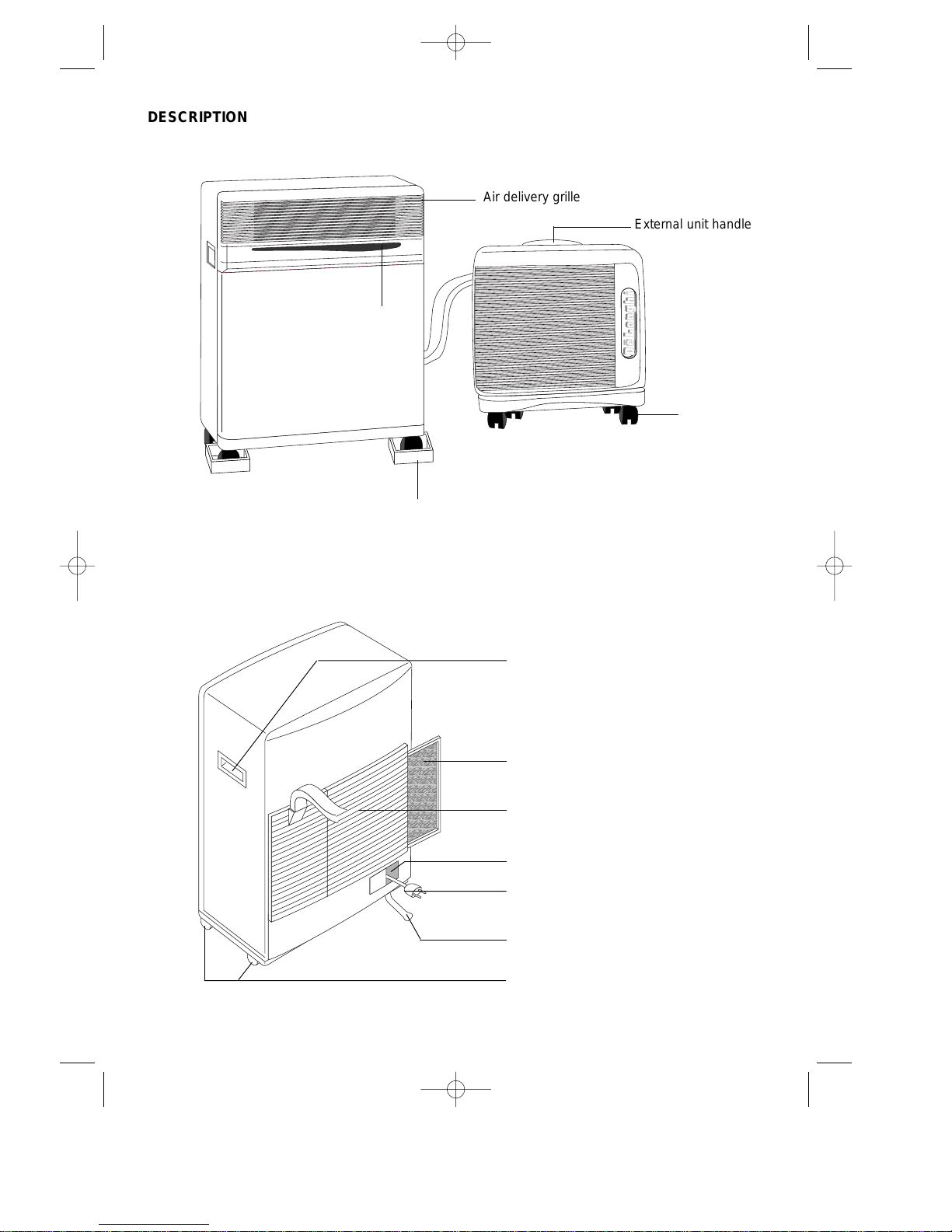
DESCRIPTION
Air delivery grille
External unit handle
Forced operations button
Castor stop
INTERNAL UNIT
EXTERNAL UNIT
INTERNAL UNIT
Carrying handle
Removable filter
Air intake grille
Power cable compartment
Power cable
Condensation drainage tube
Castors
Castors
PAC180 GB 16-05-2003 11:56 Pagina 19
20
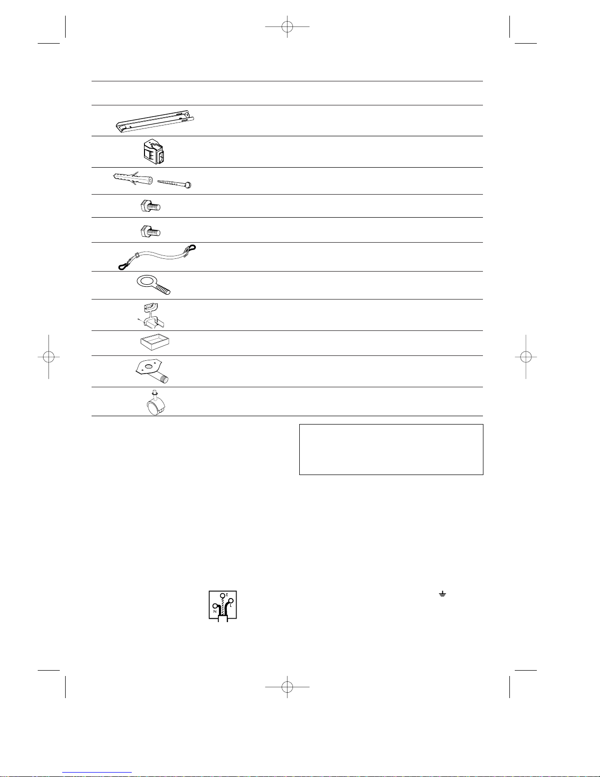
ACCESSORIES
DRAWING DESCRIPTION NO. PIECES PROVIDED
Wall-attachment bracket 2
Anchor screws + screws ø 6 mm
4
Screws M4x25 mm 4
Belt with hooks 2
Screw eye for a belt 2
Sheathing frame 1
Castor stop
2
Drain connection for condensation
with seal and two 4.2 penetrating
screws
1
TECHNICAL SERVICE
Keep the list of Technical Service Centres in a
safe place and check to find the closest Centre
(though we hope you will never have to seek their
help).
This appliance has been fitted with an HE (High
Efficiency) system for low energy consumption,
so after turning the appliance on you may have to
wait a few minutes for cool air to begin circulating.
Castors for the external unit and
washers
4
WARNING - THIS APPLIANCE MUST BE EARTHED
IMPORTANT
The wires in the mains lead are coloured in accordance with the
following code:
Green and yellow: Earth
Blue: Neutral
Brown: Live
As the colours of the wires in the mains lead may not correspond with
the coloured markings identifying the terminals in your plug, proceed
as follows:
The green and yellow wire must be connected to the terminal in the
plug marked with the letter E or the earth symbol or coloured
green or green and yellow.
The blue wire must be connected to the terminal marked with the letter
N or coloured black.
The brown wire must be connected to the terminal marked with the
letter L or coloured red.
ELECTRICAL CONNECTION (U.K. ONLY)
A) If your appliance comes fitted with a plug, it will incorporate a 13
Amp fuse. If it does not fit your socket, the plug should be cut off
from the mains lead, and an appropriate plug fitted, as below.
WARNING: Very carefully dispose of the cut off plug after removing the fuse: do not insert in a 13 Amp socket elsewhere in the
house as this could cause a shock hazard.
With alternative plugs not incorporating a fuse, the circuit must be
protected by a 15 Amp fuse.
If the plug is a moulded-on type, the fuse cover must be re-fitted
when changing the fuse using a 13 Amp Asta approved fuse to BS
1362. In the event of losing the fuse cover, the plug must NOTbe
used until a replacement fuse cover can be obtained from your
nearest electrical dealer. The colour of the correct replacement
fuse cover is that as marked on the base of the plug.
B) If your appliance is not fitted with a plug, please follow the instruc-
tions provided below:
Support block for external unit
2
Screws M6 mm 2
PAC180 GB 16-05-2003 11:56 Pagina 20
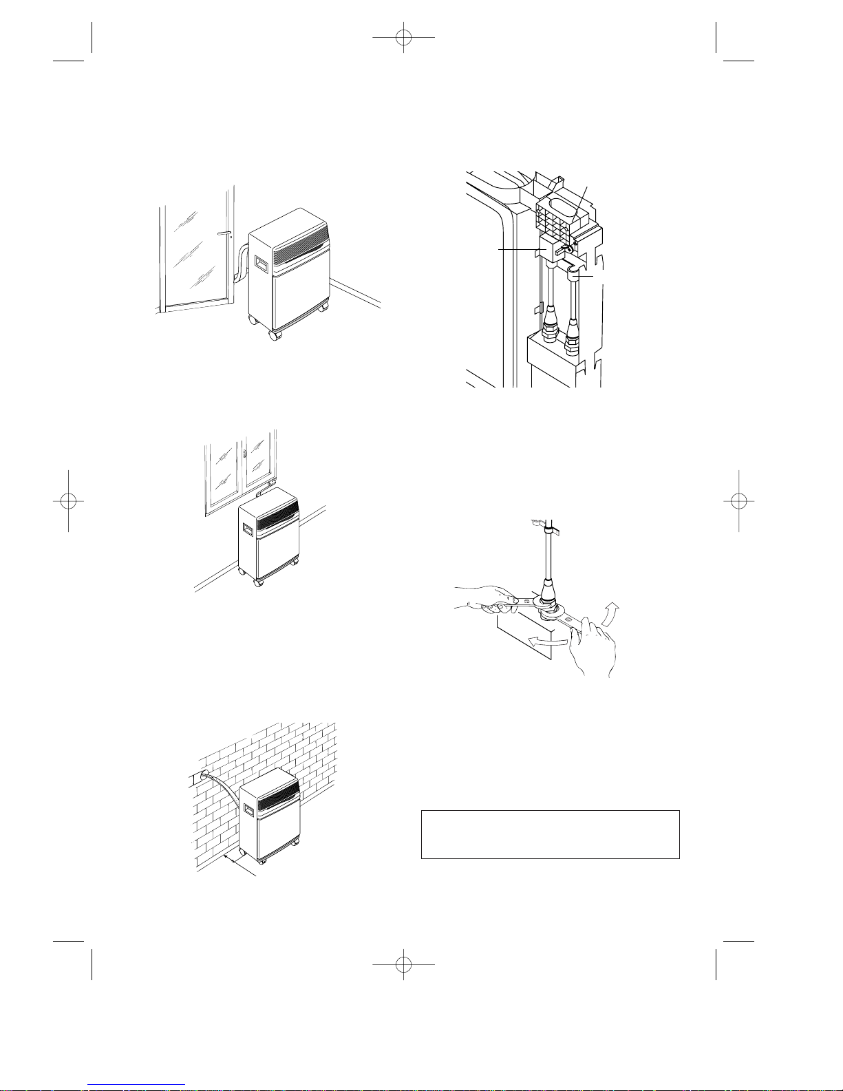
INSTALLATION
The sheathing that connects the external to the
internal unit may pass:
a) through a slightly-open window or door;
b) through a small hole (5.5 cm x 2.5 cm) drilled
in the lower part of a door or in a window
frame by using the frame provided.
USE OF RAPID COUPLINGS
In addition to the methods described above, the
sheathing that joins the external to the internal unit
may also be drawn through a hole (about 6 cm. in
diameter) drilled in a wall linked to the outside.
In this case, the hook-ups with the external unit
must be disconnected as follows:
1) Remove the plug from the electric outlet;
2) Remove the handle by loosening the two
screws and then slipping off the facing.
3) Remove the U bolt by loosening the two
screws.
4) Remove the sheath stop by loosening the two
screws.
5) Using a 24-version wrench, unscrew the union
on the coupling. At the same time, hold the end
of the flexible tube tight by using a 21-version
wrench. Repeat this operation for the second
union using a 24- and a 19-version wrench.
6) Disconnect the condensation tube from the
rubber holder.
7) Loosen the shield’s two self-threading screws
and disconnect the electric hook-up unit.
The path of the connecting sheath should
be as straight as possible, without sharp
curves or kinks.
21
ø6
cm 30
SHEATH STOP
ELECTRIC
HOOK-UP
SHIELD
U BOLT
PAC180 GB 16-05-2003 11:56 Pagina 21
To re-connect the detached ends of the sheath to
the internal unit, you must repeat operations 1
through 7 in reverse order, being careful to
observe the following precautions:
• Before drawing the sheath through the hole in
the wall, you should wrap the threaded ends of
the speedy couplings with friction tape or the
like as a protective measure.
• Fit the upper two cooling junctures into the two
lower ones and hand-screw them several turns
while checking to be certain they are well-fitted, and then tighten them with the wrenches
used earlier.
• After having hooked up the two cooling junctures, tighten the U bolts.
• Check the grip on the cooling junctures by wetting the joints with a little soapy water.
No bubbles should appear.
Caution:
We recommend that the disconnecting and connecting of the rapid couplings be carried out only
by qualified technicians.
INTERNAL UNIT
Install the internal unit inside the room to be airconditioned. This is usually done under a window
or at least close to an outside wall.
The internal unit must be placed “on the level”,
with the help of the castor-stops provided. No
obstacles should block this unit’s in-take (suction
grille) or out-take (outlet grille) areas.
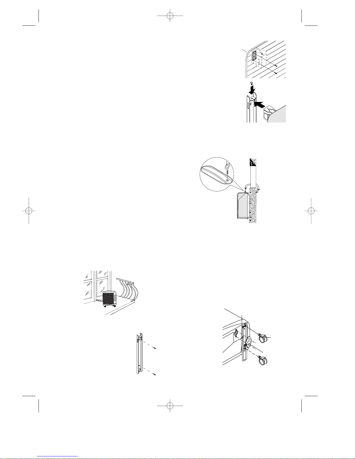
EXTERNAL UNIT
The external unit may be placed on a terrace or
balcony, in which case the brackets need not be
used.
The external unit can be attached to a wall with the
accessories included as follows:
1) Attach the bracket to the
wall while taking care to
place it as indicated in the
drawing. Use the included
template located on the
plastic cover in order to drill
the holes.
2) Screw the support blocks
to the external unit with
the included M4mm
screws while taking care
to place them so that the
hole for the screws is on
the upper side.
3) Attach the external unit to
the bracket by means of
the M6mm screws.
For temporary installation it is possible to hang the
external unit as illustrated in the drawing. In this
case, use the included straps by attaching them to
the eye hooks. Before inserting the eye hooks
remove the rubber plugs.
The external unit may be installed above or at the
same height as the internal unit, on the condition
that the difference is no more than 1.5 m.
The suction and air-delivery portions of external
unit must not be blocked by obstacles of any
nature.
The distance between the back of the appliance
and the wall must be six (6) cm.
The condensation which forms while this appliance is running (summertime operations) is disposed of by evaporation from the external unit.
If the humidity is too high (in special cases), you
must use the drainage coupling provided to get rid
of condensation. This device must be mounted on
the bottom of the
external unit (see
drawing) after the
rubber plug has
been removed.
We strongly recommend that you protect the external unit
from rain, snow,
direct sunlight and
water dripping from
the roof.
22
Castor
Drainage
Coupling
Gasket
1
2
PAC180 GB 16-05-2003 11:56 Pagina 22
 Loading...