

Page 1
Page 2

DLS
DE’LONGHI ’EU’ MW665F 0119617801
SERVICE
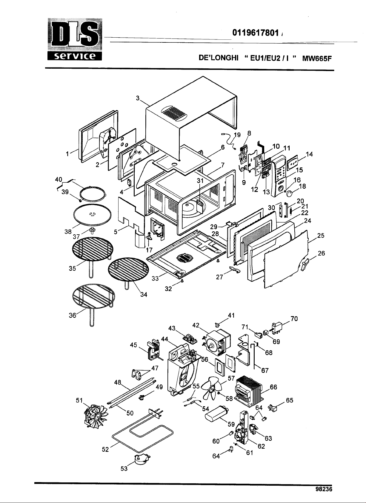
Pos Codice Italiano English Francais Deutsch Espanol
01 690446 SCHIENALE REAR PANEL PANNEAU ARRIERE RUECKWAND RESPALDO
02 536652 ISOLANTE INSULATOR ISOLANT ISOLIERSTOFF AISLANTE
03 709155 MANTELLO HOUSING ENVELOPPE GEHAEUSE CHASIS ENVOLVENTE
04 536878 ISOLANTE INSULATOR ISOLANT ISOLIERSTOFF AISLANTE
05 536651 ISOLANTE INSULATOR ISOLANT ISOLIERSTOFF AISLANTE
06 536599 ISOLANTE INSULATOR ISOLANT ISOLIERSTOFF AISLANTE
07 709158 CAVITA CAVITY CAVITE HOHLRAUM CAVIDAD
08 5219101500SCHEDA BOARD FICHE PLATINE FICHA
09 506545 POTENZIOMETRO POTENTIOMETER POTENTIOMETRE POTENTIOMETER POTENCIOMETRO
10 5219101300MEMBRANA MEMBRANE MEMBRANE MEMBRANE MAMBRABA
11 5319107200TASTIERA KEYBOARD CLAVIER DRUCKKNOPFTAFEL TECLADO
12 536761 TASTIERA KEYBOARD CLAVIER DRUCKKNOPFTAFEL TECLADO
13 536760 TASTIERA KEYBOARD CLAVIER DRUCKKNOPFTAFEL TECLADO
14 5919115200VETRINO GLASS VERRE GLAS VIDRIO
15 5919115100CRUSCOTTO CONTROL PANEL Tableau de Commande BEDIENUNGSBLENDE Marco Panel Mandos
16 611900 MOLLA SPRING RESSORT FEDER MUELLE
17 512292 LAMPADA LAMP LAMPE LAMPE LAMPARA
18 536758 MANOPOLA KNOB BOUTON KNOPF MANDO
19 5219100000SONDA FEELER SONDE FUEHLER SONDA
20 536384 GANCIO HOOK CROCHET HAKEN GANCHO
21 612003 MOLLA SPRING RESSORT FEDER MUELLE
22 737975 PORTA DOOR PORTE TUER PUERTA
24 536332 CORNICE FRAME ENCADREMENT RAHMEN MARCO
25 592982 FRONTALE FRONT PANEL PANNEAU AVANT VORDERWAND PARTE DELANTERA
26 536334 MANIGLIA HANDLE POIGNEE GRIFF MANILLA
27 709162 CERNIERA INF. HINGE LOWER CHARNIERE INF. SCHARNIER (UNTEN) BISAGRA INF.
28 536565 CORNICE FRAME ENCADREMENT RAHMEN MARCO
29 709161 CERNIERA SUP. HINGE UPPER CHARNIERE SUP. SCHARNIER (OBEN) BISAGRA SUP.
30 536347 GUIDA RUNNER GLISSIERE FUEHRUNG GUIA
31 536380 CHIUSURA CLOSURE FERMETURE VERSCHLUSS CIERRE
32 532710 GOMMINO RUBBER PAD PARE CHOCS PUFFER GUARNICION
33 690448 BASAMENTO BASE SOCLE UNTERGESTELL BASE
34 612010 GRIGLIA GRID GRILLE GITTER PARRILLA
35 612009 GRIGLIA GRID GRILLE GITTER PARRILLA
36 612024 GRIGLIA GRID GRILLE GITTER PARRILLA
37 535127 TRASCINATORE PULLER ENTRAINEUR MITNEHMER ARRASTRADOR
38 536473 PIATTO PLATE PLAT TELLER PLATO
39 535762 RUOTA CASTOR ROULETTE RAD RUEDA
40 552577 SUPPORTO SUPPORT SUPPORT HALTER SOPORTE
41 521466 TERMOSTATO THERMOSTAT THERMOSTAT THERMOSTAT TERMOSTATO
42 512985 MAGNETRON MAGNETRON MAGNETRON MAGNETRON MAGNETRON
43 521659 SCHEDA BOARD FICHE PLATINE FICHA
44 536349 COCLEA ARCHIMEDES SCREW VIS D’ARCHIMEDE SCHNECKE TORNILLO SIN FIN
45 512987 MOTORE PLASET MOTOR PLASET MOTEUR PLASET MOTOR PLASET MOTOR PLASET
47 537421 SUPPORTO SUPPORT SUPPORT HALTER SOPORTE
48 512980 RESISTENZA SUP. Heating Element Upper Element Chauffant Sup. HEIZELEMENT OBEN RESISTENCIA SUP.
49 521466 TERMOSTATO THERMOSTAT THERMOSTAT THERMOSTAT TERMOSTATO
50 512979 RESISTENZA INF. Heating Element Lower Element Chauffant Inf. HEIZELEMENT UNTEN RESISTENCIA INF.
51 512422 MOTORE MOTOR MOTEUR MOTOR MOTOR
52 512981 RESISTENZA HEATING Element ELEMENT Chauffant HEIZELEMENT RESISTENCIA
53 512767 MOTORE MOTOR MOTEUR MOTOR MOTOR
54 512782 DIODO DIODE DIODE DIODE DIODO
55 512327 DIODO DIODE DIODE DIODE DIODO
56 536683 GUARNIZIONE GASKET JOINT DICHTUNG GUARNICION
57 536578 VENTOLA PLASET FAN PLASET HELICE PLASET FLUGELRAD PLASET VENTILADOR PLASET
58 611916 MOLLA SPRING RESSORT FEDER MUELLE
59 513117 CONDENSAT. 1,05uF CAPACITOR 1,05uF CONDENSATEUR 1,05uF KONDENSATOR 1,05uF CONDENSAD. 1,05uF
60 511854 MICROINTERRUTTORE MICROSWITCH MICRORUPTEUR MIKROSCHALTER MICROINTERRUPTOR
61 612004 MOLLA SPRING RESSORT FEDER MUELLE
62 536365 SUPPORTO SUPPORT SUPPORT HALTER SOPORTE
63 536366 CAMMA CAM CAME NOCKE LEVA
64 511855 MICROINTERRUTTORE MICROSWITCH MICRORUPTEUR MIKROSCHALTER MICROINTERRUPTOR
65 536367 CAMMA CAM CAME NOCKE LEVA
66 513052 TRASFORMATORE TRANSFORMER TRANSFORMATEUR TRANSFORMATOR TRANSFORMADOR
67 612008 ASTA ROD TIGE STANGE BARRA
68 612028 MOLLA SPRING RESSORT FEDER MUELLE
69 537312 TRASCINATORE PULLER ENTRAINEUR MITNEHMER ARRASTRADOR
70 5119100200TERMOREGOLATORE THERMOREGULATOR THERMOREGULATEUR THERMOREGLER TERMORREGULADOR
71 537313 BLOCCHETTO BLOCK BLOC STUECK BLOQUE
DE’LONGHI "EU" MW665F COD.0119617801 2685/1998/0
- Pag. 1/1 -
Page 3
FORNI MICROONDE / MICROWAVE OVENS
SCHEDA TECNICA 98038
MIKROWELLENGERÄTE / FOURS A MICRONDES
DATI TECNICI / TECHNICAL DATA / TECHNISCHE DATEN
DONNEES TECHNIQUES / DATOS TECNICOS
HORNO MICROONDAS
DE' LONGHI MW 665 F
Voltaggio / Voltage / Spannung / Voltage / Voltaje
Max.potenza assorbita / Max. input power / Max.Leistungsaufnahme
Max.puissance absorbée / Max.potencia absorbida
Potenza microonde / Microwave output / Mikrowellenleistung
Puissance de sortie microondes / Potencia cedida microondas
Magnetron
- termostato sicurezza / safety thermostat / Sicherheitsthermostat
thermostat de sécurité / Termostato de seguridad
Commutatore / Change over switch / Umschalter / Commutateur / Conmutador
Ventilatore cavità / Cavity ventilator / Garraum-Ventilator
Ventilateur du four / Ventilador del horno
- avvolgimento / winding / Wicklung / bobinage / envolvimiento
Sensore temperatura NTC / NTC temperature sensor / Temperaturfülher NTC
Sensour de temperature NTC / Sensore de temperatura NTC
Resistenza forno / Oven heating element / Ofen-Heizkörper
Elément chauffant du four / Resistencia horno
Resistenza grill / Grill heating element / Grill-Heizkörper
Elément chauffant gril / Resistencia grill
Attuatore a cera / Damper for air duct / Öffner für Belüftungskanal
Actionneur petit guichet / Actuador puertita
Type / W
V / Hz
W
W
Type
Type
°C
Type
Type
W
Type
°C
R1
R2
W
°C
230 - 50
2850
850
Goldstar2M226
Texas PK1
145
Elettronico / Electronic
Plaset
23
Ω
120 (at 20 °C)
Bowthorpe Thermometrics JS3684
-10 / 220
178V / 271W
47V / 304W
1400
ELTEK 100332.14 / 3.5
0 - 105
Trasformatore / Transformer / Transformator / Transformateur / Transformador
- avvolgimento primario / primary winding / Wicklung primär
bobinage primaire / envolvimiento primario
- avvolgimento secondario / secondary winding / Wicklung sekundär
bobinage secondaire / envolvimiento secondario
- avvolgimento filamento / filament winding / Glühfaden-Wicklung
bobinage filament / envolvimiento filamento
Condensatore / Capacitor / Kondensator / Condensateur / Condensador
Diodo / Diode / Diode / Diode / Diodo
Ventilatore / Ventilator / Ventilator / Ventilateur / Ventilador
- avvolgimento / winding / Wicklung / bobinage / envolvimiento
Contaminuti / Timer / Zeitschaltuhr / Programmateur / Programador
- avvolgimento / winding / Wicklung / bobinage / envolvimiento
Microinterruttori / Microswitches / Mikroschalter
Microrupteurs / Microinterruptores
Diodo protezione/Protection diode/Schutzdiode
Diode de protection/Diodo de protecciòn
Motore piatto / Turntable motor / Drehteller-Motor
Moteur plateau tournant / Motor del plato giratorio
Lampada / Lamp / Lampe / lampe / Lámpara
Type / W
Type
V / Ω
V / Ω
V
µF
Type
Type
Type
V / A
Type
Type
W
W
DeoBo
7501A
230 -1.7
2200-98.5
3.2
1.05
FciHV0309
Plaset - 20
Ω
170
Elettronico / Electronic
SodecoóSaiaó Xgaw óCrouzet
250 / 12
FCI HV 06X1P5
JAE ST-16MN73SYAWF
3 / 2.5 W
25
Fusibile / Fuse / Schmelzsicherung / Fusible / Fusibile
A
EM8A type Fusit or Omega
1
Page 4
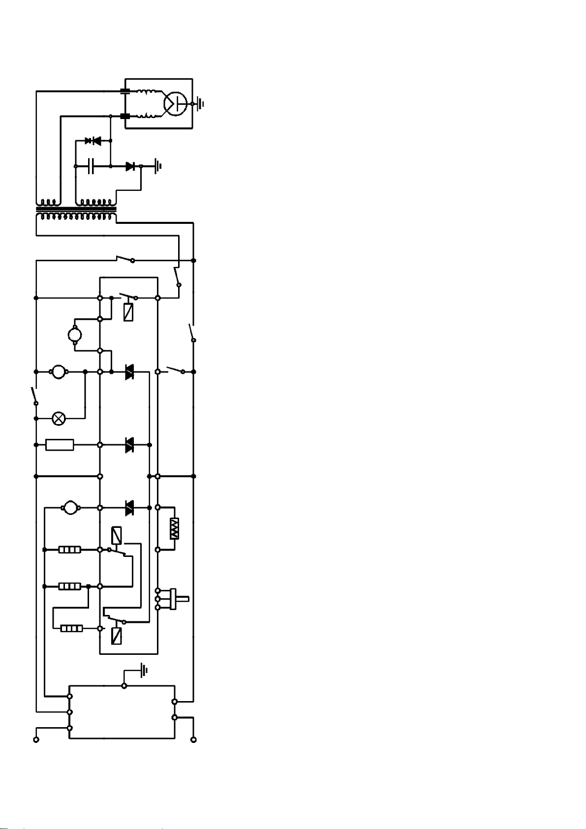
SCHEMA ELETTRICO / ELECTRIC DIAGRAM / SCHALTPLAN
SCHEDA TECNICA 98038
LEGENDA - LEGEND - ZEICHENERKLÄRUNG - LEGENDE - LEGENDA
AS Attuatore sportellino Damper for air duct Öffner für Belüftungskanal Actionneur petit guichet Actuador puertita
DM Motore piatto rotante Turntable motor Drehteller-Motor Moteur plateau tournant Motor del plato giratorio
EC Controllo elettronico Electronic control Elektronisch Kontrolle Contrôle électronique Control electrònico
ENC Encoder Encoder Encoder Encoder Encoder
F1....F13 Contatti scheda elettronica Electronic board contacts Platinenanschlußklemmem Contacts C.I. Contactos del control electronico
FM Ventilatore magnetron Magnetron ventilator Magnetron-Ventilator Ventilateur magnetron Ventilador magnetron
HVC Condensatore alta tensione High voltage capacitor Hochspannungskondensator Condensateur h.t. Condensador a.t.
HVD Diodo rettificatore a.t. High voltage retifier diode Hochspannungsdiode Diode h.t. Diodo a.t.
HVT Trasformatore alta tensione High voltage transformer Hochspannungstransformator Transformateur h.t. Transformador a.t.
J1 Connessione per Membrane Switch Membrane Switch connector Membrane Switch Kontakt Contacts Membrane Switch Contactos del Membrane Switch
J2 Connessione per Encoder Encoder connector Encoder Kontakt Contacts Encoder Contactos del Encoder
J3 Contatto sensore NTC NTC sensor contacts NTC Sondenkontakt Contacts détecteur de température Contactos del sensor de temperatura
LOG Micronterruttore logico Logical microswitch LOG Mikroschalter Microrupteur logique Microinterruptor lògico
MGT Magnetron Magnetron Magnetron Magnetron Magnetron
MON Microinterruttore monitor Monitor microswitch Monitor Mikroschalter Microrupteur monitor Microinterruptor monitor
NF Filtro antidisturbo + Fusibile Antinoise filter + Fuse Netz-Filter + Schmelzsicherung Filtre + Fusible Filtro + Fusible
NTC Sensore temperatura Temperature sensor Temperaturfülher Détecteur de température Sensor de temperatura
OL Lampada forno Oven light Ofenbeleuchtung Lampe du four Lámpada horno
PDX Diodo di protezione Protection diode Schutz diode Diode Protection Diode Protecciòn
PRI Micronterruttore primario Primary microswitch Mikroschalter primär Microrupteur primaire Microinterruptor primario
RF1 / RF2 Resistenza forno Oven heating element Ofen-Heizkörper Elément chauffant du four Resitencia horno
RG Resistenza grill Grill heating element Grill-Heizkörper Elément chauffant gril Resistencia grill
RL1 Relè microonde Microwaves relais Relais für Mikrowellen Rélais microondes Conectador microondas
RL2 Relè grill Grill resistance relais Relais für Grillheizelement Rélais grill Conectador grill
RL3 Relè fan Fan resistances relais Relais für Umluftheizelement Rélais résistances four Conectador resitencia horno
TY1 Triac ausiliari Auxiliars devices Triac Triac für Hilfskomponente Triac auxiliaires Triac dispositivos auxiliares
TY2 Triac attuatore sportellino Damper Triac Triac für Umluftklappe Triac actionneur Triac actuador puertita
TY3 Triac motore aria calda Fan motors Triac Triac für Ventilator Triac moteur ventilation Triac motor ventilador
SEC Microinterruttore secondario Secondary microswitch Mikroschalter sekundär Microrupteur secondaire Microinterruptor secundario
TH.MGT Protettore magnetron Magnetron protector Magnetron Temperaturbegrenzer Protecteur magnetron Protector magnetron
V Ventilatore cavità Hot Air Fan Heissluff-Gebläse Ventilateur air chaude Ventilador convezione
SCHEMA ELECTRIQUE / ESQUEMA ELECTRICO
MGT
FA F
PDX
HVD
HVC
HVT
MON
SEC
FMOL
AS
DM
V
RG
F6F5F13F12F11F2F10F8 F9EC
TY1TY2TY3
RL2
TH.MGT
F4
RL1
PRI
LOG
F3F1
J3
NTC
J2
RF2
RF1
L2 L1L
F7
RL3
GND
ENC
N N1
Porta aperta / Door open / Tür auf / Porte ouverte / Puerta abierta
L
NF
N
2
Page 5

SCHEMA ELETTRICO / ELECTRIC DIAGRAM / SCHALTPLAN
Colori Colours Farben Coleurs Colores
Bianco White Weiß Blanc Blanco
Blu Blue Blau Bleu Azul
Giallo-Verde Yellow/Green Gelb/Grün Jaune/Vert Amarillo/Verde
Grigio Gray Grau Gris Gris
Marrone Brown Braun Marron Castano
Nero Black Schwarz Noir Negro
Rosso Red Rot Rouge Rojo
SCHEDA TECNICA 98038
SCHEMA ELECTRIQUE / ESQUEMA ELECTRICO
GIALLO / VERDE
L N
RG
PRI
MGT
NOC
NF
GIALLO/VERDE
L2
TH.MGT
ROSSO
NERO
GND
L1
NERO
FM
N1
F FA
NERO
NERO
N L
RF1
NTC
HVD
al contatto J3 della scheda /
to the J3 contact on the board
HVC
PDX
V
RF2
HVT
BIANCO
ROSSO
BLU
C
NC
MON
NO
C
C
NO
SEC
LOG
MARRONE
MARRONE
OL
DM
ENC
AS
al contatto J2 della scheda /
to the J2 contact on the board
MARRONE
BLU
BLU
BLU
BIANCO
BIANCO
NERO
NERO
GRIGIO
dalla sonda NTC /
from the NTC probe
EC
GRIGIO
ROSSO
all'ENCODER /
J2
J3
J1
F10
SWITCH
GRIGIO
to the ENCODER
F11F3F1F2F4F5F6
MEMBRANE
F12
ROSSO
BIANCO
MARRONE
F7 F9 F8
F13
GRIGIO
MARRONE
BIANCO
MARRONE
3
Page 6

PRECAUZIONI DA ADOTTARE CERCANDO GUASTI
SCHEDA TECNICA 98038
A differenza di altre apparecchiature, il forno a microonde è un'unità ad alto voltaggio ed amperaggio.Nonostante
il suo normale utilizzo non presenti alcuna pericolosità, si deve usare estrema cautela durante le riparazioni :
- Toglietevi l' orologio operando in prossimità del magnetron.
- Attenzione al condensatore ad alto voltaggio, potrebbe rimanere carico per diverso tempo dopo che
il forno ha cessato di funzionare. E' opportuno scaricarlo ogni volta collegandone entrambi i poli con la
massa per mezzo di un cavetto adeguatamente isolato.
- I circuiti secondari del trasformatore presentano capacità di alto voltaggio ed alto amperaggio, è quindi
estremamente pericoloso lavorare nelle vicinanze di questo componente quando il forno è alimentato.
- Non toccare nessun filo con le mani o con attrezzi non isolati durante il funzionamento.
- Non eseguire misure di tensione sul circuito ad alto voltaggio e sul filamento del magnetron.
- Accertarsi che la porta non sia allentata o mancante. Se le viti non sono perfettamente strette ci possono
essere fughe di microonde.
- Accertarsi che tutte le connessioni elettriche non siano lasche prima di alimentare il forno.
- Accertarsi che non ci siano fughe di microonde seguendo l' apposita procedura.
- Non inserire alcun oggetto metallico attraverso le fessure della lampada o altre fessure del forno, perchè
tali oggetti potrebbero funzionare da antenna e causare fughe di microonde.
ATTENZIONE RADIAZIONI A MICROONDE
- LE PERSONE NON DEVONO ESSERE ESPOSTE ALL'ENERGIA A MICROONDE CHE PUÒ
ESSERE IRRADIATA DAL MAGNETRON O DA ALTRO DISPOSITIVO GENERATORE DI
MICROONDE NEL CASO DI UN UTILIZZO O CONNESSIONE NON CORRETTA.
- TUTTE LE CONNESSIONI A MICROONDE DI ENTRATA E DI USCITA, LE GUIDA D'ONDA, LE
FLANGE E I GIUNTI DEVONO ESSERE SICURI.
- NON FAR FUNZIONARE IL GENERATORE SENZA UN CARICO PREVISTO PER ASSORBIRE
L'ENERGIA A MICROONDE.
- NON GUARDARE MAI ALL'INTERNO DI UNA GUIDA D'ONDA APERTA O DI UNA ANTENNA
MENTRE IL GENERATORE È IN FUNZIONE.
- NON FAR FUNZIONARE IL FORNO, E NON PERMETTERE LA BENCHÈ MINIMA POSSIBILITÀ
CHE IL FORNO POSSA FUNZIONARE A PORTA APERTA
Eseguire i seguenti controlli di sicurezza su tutti i forni da riparare prima di attivare il
magnetron o altro dispositivo generatore di microonde, ed eventualmente eseguire le
necessarie riparazioni :
- Funzionamento del dispositivo di chiusura.
- Corretta chiusura della porta.
- Stato della chiusura della guarnizione e delle superfici di battuta.
- Danneggiamento od allentamento delle cerniere e degli agganci di chiusura.
- Segni evidenti di caduta od uso improprio.
Ogni componente difettoso o non correttamente tarato, posizionato nelle seguenti aree: chiusura, monitor,
guarnizione, porta, sistema di generazione e trasmissione delle microonde deve essere riparato, sostituito,tarato.
ISTRUZIONI PER GLI INTERVENTI SUL MOTORE GIREVOLE
-Per accedere al motore tranciare le linguette che mantengono il coperchio
del motore ( vedi fig. A ).
- Dopo l'intervento rimontare tassativamente il coperchio con 2 viti
autofilettanti 4,2 x 9,5 senza punta.
ISTRUZIONI PER GLI INTERVENTI SUL CAVO DI ALIMENTAZIONE
- Quando si cambia o comunque si deve intervenire sul cavo di
alimentazione, è tassativo ripristinare la clip (per cavo PVC)
che lo tiene teso ed aderente allo schienale (vedi fig.).
FORNO VISTO DA SOTTO
FORNO VISTO DA DIETRO
cavo elettrico
Fig.A
Fig.B
clip
4
Page 7

MISURA DELLE MICROONDE DISPERSE
SCHEDA TECNICA 98038
Il controllo delle microonde disperse deve essere effettuato dopo ogni riparazione ,
sostituzione o regolazione delle parti, del sistema di aggancio e chiusura porta, del modulo
interruttori, del magnetron.
- mettere un recipiente con 250cc di acqua al centro della
cavità forno
- Accendere il forno alla massima potenza.
-Con un misuratore di campo per microonde a 2.450MHZ,
controllare attentamente le dispersioni muovendo
lentamente la sonda lungo il perimetro di battuta della
porta lungo le fughe del mobile. Per una corretta
misurazione attenersi scrupolosamente alle istruzioni d'uso
dello strumento.
- La dispersione massima ammessa è di 5 mW cm a 5 cm.
2
Normalmente viene assicurata una dispersione più bassa
del minimo consentito (<1mw/cm ).
2
MISURA DELLA POTENZA EMESSA DAL MAGNETRON.
NOTA : controllare la tensione di alimentazione, se dovesse essere inferiore a 230V
la potenza emessa dal magnetron risulterà più bassa.
- Riempire un contenitore di vetro con esattamente 1 litro d'acqua a temperatura ambiente (deve
essere compresa tra 15 e 24°C).
- Mescolare col termometro e rilevare l'esatta temperatura iniziale dell'acqua (T1).
- Posizionare il contenitore sul vassoio di vetro al centro del forno.
- Selezionare la potenza massima e far funzionare il forno per esattamente 63 secondi.
- Mescolare di nuovo l'acqua col termometro e rilevare la temperatura finale dell'acqua (T2).
- La diffeenza tra la temperatura iniziale (T1) e la temperatura finale (T2), dovrebbe essere di circa
10 -12°C.
- La potenza emessa dal magnetron può essere calcolata con la seguente
formula : P (W) = 70 x ( T2 - T1 ).
Se la potenza è inferiore alla nominale di oltre il 15 %, sostituire il magnetron e/o verificare
la capacità del condensatore A.T.
5
Page 8

SCHEDA TECNICA 98038
PROCEDURA DI CONTROLLO COMPONENTI
ATTENZIONE : Eseguire i test di continuità con la spina disinserita e dopo aver scaricato il
condensatore cortocircuitando i terminali a massa con un cacciavite isolato
per 5000V. minimo
MAGNETRON
1) Scollegare il componente e collegare lo strumento ai terminali
del filamento : con il TESTER ohm x 1, la lettura deve risultare
inferiore a 1 ohm.
TRASFORMATORE
2) Scollegare tutte le connessioni del trasformatore con il
TESTER ohm x 1, le letture normali , a temperatura ambiente
dovrebbero essere :
2.1) Primario (vedi dati tecnici)
2.2) Filamento inferiore 1Ω
2.3) Secondario (vedi dati tecnici)
CONDENSATORE
ALTA TENSIONE 3) Scollegare tutte le connessioni del condensatore con il
TESTER ohm scala massima collegare lo strumento ai termi nali del condensatore : in primo momento si deve avere una
lettura come di continuità, che poi deve tornare a valore infinito.
3.1) La lettura tra ciascuno dei terminali e la cassa esterna deve
indicare un valore infinito.
Terminali
Cassa esterna
DIODO
ALTA TENSIONE
4 La continuità del diodo non si può misurare con un TESTER
mormale, in quanto presenta una caduta di tensione di 6.3V o
superiore. Si consiglia di collegare i terminali del diodo con
un alimentatore a 12 V e una lampadina da 2,5 V collegata in serie.
.
Alimentatore 12V
- +
Lamp 2.5V
6
Diodo
Page 9

PRECAUTIONS TO BE TAKEN WHEN TROUBLESHOOTING
SCHEDA TECNICA 98038
Unlike other appliances, microwave oven is a high voltage and high amperage unit. Even if you can
use it normally without any danger, you should be very careful during maintenance operations:
- Take off your watch when operating close to magnetron.
- Attention : the H.V. condenser could still be charged for about 30 seconds after the oven has been
switched off.
It is advisable to discharge capacitor each time by both poles through a suitably insulated cable.
- Secondary circuits of the transformer have a high voltage and a high amperage capacity, and
therefore it is extremely dangerous to work near this component when oven is plugged in.
- Never touch any wires with bare hands or with no-insulated tools when oven is operating.
- Do not measure voltage on high-voltage circuit or magnetron filament.
- Make sure that door is not loose or missing. If screws are not perfectly tightened, it may lead
to microwave leaks.
- Make sure all electric connections are well tightened before turning on the oven.
- Make sure there is no microwave leakage following the proper procedure.
- Do not insert any metal object either through lamp crevice or any other oven crevice as such
objects could act as an antenna and cause microwave leaks.
ATTENTION
When fuse blows, always interlock system efficiency first (all microswitches), before turning the
oven on again. Should a microswitch be found defective, always change all microswitches.
ATTENTION: MICROWAVE RADIATION
- PERSONNEL SHOULD NOT BE EXPOSED TO MICROWAVE ENERGY WHICH MAY RADIATE FROM
THE MAGNETRON (OR OTHER MICROWAVE GENERATING DEVICES) IF IT IS IMPROPERLY USED
OR CONNECTED. ALL INPUT AND OUTPUT MICROWAVE CONNECTIONS, WAVEGUIDES, FLANGES
AND GASKETS MUST BE SECURE.
- NEVER OPERATE THE DEVICE WITHOUT A MICROWAVE ENERGY ABSORBING LOAD, INSIDE
THE OVEN CAVITY.
- NEVER LOOK INTO AN OPEN WAVEGUIDE OR ANTENNA WHILE THE DEVICE IS WORKING.
- NEVER OPERATE OR ALLOW THE OVEN TO BE OPERATED WITH THE DOOR OPEN .
Make the following safety checks on all ovens to be serviced before activating the magnetron, and
make repairs as necessary :
- Interlock operation.
- Proper door closing.
- Seal and sealing surfaces state
- Damage or loosening of hinges and latches,
- Evidence of dropping or abuse.
Any defective or misadjusted components in the interlock, monitor, door seal and microwave generation and
transmission systems shall be repaired, replaced, or adjusted .
INSTRUCTIONS FOR MAINTENANCE ON TURNTABLE MOTOR
OVEN BOTTOM VIEW
-To reach the motor, cut the metal reeds that retain
the motor cover (see fig.A ).
-After the operation set back the motor cover and
fix it with 2 self-threaded screws 4.2x9.5 with no sharp end.
OVEN BACK VIEW
Fig.A
INSTRUCTIONS FOR MAINTENANCE ON POWER SUPPLY CABLE
- When you replace or work on the power supply cable,
make sure to fix afterwards the wire with the clip (see fig. B).
7
electric wire
clip
Fig.B
Page 10

MICROWAVE LEAKAGE TEST
SCHEDA TECNICA 98038
This test has to be done after every manteinance operation regarding the door and the
whole closure system, microswitches and magnetron.
Test equipment:
- 600 ml beaker
- Microwave survey meter
Test procedure:
- Place 250 ml water in a beaker and place it in the centre of the oven
- Turn on oven, set timer for 5 minutes at full power
- Hold the probe of the microwave survey meter perpendicular to the door edge of the
oven and scan it very slowly.
Test the following areas:
- Door and control panel
- All ventilation openings
- All lockseams
- Weld at borrom
- Bottom plate
Operations:
- Open the door to the position at which the oven is just about to turn off, scan the door
perimeter.
- The distance between door and probe must be at least 5 cm
- Maximum allowable leakage is 4 mW / cm
2
MAGNETRON POWER TEST
The standard test load is one litre (1000 ml) of water with an initial temperature between
15 - 24 °C (58 - 75 °F) in a 1000 ml beaker. Do not use any other load or dish otherwise test result
will vary from standard.
Test procedure:
- Measure and adjust the voltage of the AC power supply to its correct value.
Bear in mind that test result is influenced by the voltage supply value.
Too low or too high voltage will not determine an accurate measurement.
- Place beaker containing exacly 1000 ml of water at 15 - 24 °C in the centre of the oven.
Use an accurate thermometer to read the initial water temperature (T1).
- Switch-on the appliance for exactly 63 seconds at full power.
- At the end of this period, stir the water quickly and read the water final temperature (T2).
The difference between the final temperature (T2) and the initial temperature (T1) is the
temperature rise.
Results:
- The microwave power of the oven can be determined by the following formula:
P (W) = 70 x (T2 - T1)
If power is more than 15% off the nominal power of the M.W., then verify High Voltage
Capacitor and eventually change magnetron.
8
Page 11

COMPONENTS TEST PROCEDURE
SCHEDA TECNICA 98038
MAGNETRON 1. Chek resistance: Normal reading:
Across the filament terminals Less than 1 Ohm
of the magnetron with an Ohm meter on R x 1 scale.
2. Chek resistance: Normal reading:
between each filamet terminals infinite Ohm
of the magnetron and the chassis
ground with an ohm-meter set on
highest scale
HIGH VOLTAGE
1. Measurement the resistance: Normal reading:
TRANSFORMER with ohm-meter on R x 1 scale.
a) Primary winding: - appoximately 1.24 Ohm
b) Filament winding: - less than 1 Ohm
c) Secondary winding: - appoximately 87 Ohm
2. Measure the resistance: Normal reading
with an ohm-meter on highest scale
a) primary winding to ground - infinitive Ohm
b) Filament winding to ground - infinitive Ohm
HIGH-VOLTAGE 1.Measure the resistance: Normal reading:
CAPACITOR
Across the terminals of the Temporarily indicates several
capacitor with an ohm-meter on Ohm, and then gradually returns
highest scale. to infinite Ohm.
Abnormal reading:
indicates continuity or infinite
Ohm from the beginning.
Terminals
External housing
CAUTION: discharge high voltage capacitor before checking parts of high voltage circuit.
DIODE
1. Check diode:
Across the terminals with a 12V
DC supplier and 2.5V lamp circuit.
- +
Lamp 2.5V
Normal reading:
Lamp is ON or OFF depending
on polarity of voltage.
Abnormal reading:
Lamp is too bright : short circuit
Lamp is never ON : open circuit
9
 Loading...