

Page 1
RADIANT HEA
RADIANT HEA
TER WITH TERMOST
TER WITH TERMOSTAAT T
GB
GB
TERMOST
TERMOST
AA
AA
TILLA V
TILLA V
ARUSTETTU
ARUSTETTU
INFRAPUNALÄMMITIN
INFRAPUNALÄMMITIN
SF
SF
GB 21-07-2003 16:05 Pagina 1
Page 2
2
RADIANT HEATER WITH TERMOSTAT
Technical Data
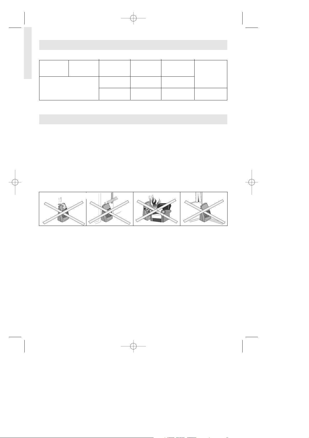
Type Category Maximum Medium Low Gas pressure
Input Input Input
KW g/h KW g/h KW g/h
4.20 305 2,85 207 1,50 109 28÷30 mbar
This appliance is designed to operate with Butane, propane or mix LPG at nominal pressure:
28 ÷ 30 mbar. For a correct gas combustion the required air quantity is 8,4 m
3
/h.
WARNINGS
- ALWAYS use heater in accordance with instructions. Read the instructions book carefully
and keep it in a safe place.
- This appliance requires a rubber tube and a pressure regulator in accordance with the
law in force. If not supplied check with your gas supplier.
- Use ONLY in a well ventilated area.
- This appliance MUST NOT be used in basements, high rise flats, bathrooms or
bedrooms and in rooms having volume less than 15 m
3
(30 m3in living rooms).
- This appliance emits the combustion residues in the room in which is used.
- DO NOT place clothes or other materials on the heater, as apart from the danger of fire
their presence could affect the efficient working of the appliance (fig. 1).
- DO NOT move heater from room to room when it is lit (fig. 2).
- DO NOT position heater alongside a wall or near curtains or arm-chairs etc. (fig. 3 - 4).
- ALWAYS face heater towards centre of room. Special care should be taken if the heater is on
a surface where it can move or twist on its wheels or castors if knocked by a child or dog, etc.
- Minimum Clearance : 200 mm from sides,1500 mm from front.
- Be sure installation is complying to local standard.
- The heater you have purchased is fitted with safety devices which come on in the event
of malfunctioning while the appliance is in use. If the pilot light (placed opposite the
burner) accidentally goes out, or if the room is not sufficiently ventilated, the safety device will block the gas flow, causing the heater to go off.
- Do not use the heater at high altitudes.
Gas leakages
If a leak is suspected, turn off gas at the gas bottle, open the window and air the room. DO
NOT disconnect the pressure regulator. Extinguish all naked lights. Slowly turn the gas on
and brush the connections with soapy water or liquid detergent - a gas leak will form bubbles. If a leak is found, turn the gas off and inform your Dealer. DO NOT use the heater
again until it has been inspected by your Dealer.
NEVER USE MATCHES TO FIND LEAKS.
see rating label
fig. 1
fig. 2
fig. 3 fig. 4
GB 21-07-2003 16:05 Pagina 2
Page 3

ASSEMBLY
1) Remove the polystyrene fixing the heater base plate
and the heater front panel.
Remove the heater base plate from the polystyrene.
Place the heater base plate on the floor or on a flat
surface.
Remove the two screws from the holes “A” (fig.5).
2) Position the heater’s front panel assembly over the
base plate, and align the four tabs “B” on the base with the four slots “C” (fig.6) in the
bottom of the front panel assembly. With the four tabs correctly engaged,
push the front panel assembly forwards as far as the tabs will slide in their
slots to align the screw holes “A” in the base plate with the screw holes “D”
in the bottom of the front panel assembly.
3) Fit the front panel assembly to the base plate by fixing the two screws (fig.7) (removed
previously) trough the aligned screw holes (holes D and A).
Place the gas cylinder in the gas cylinder compartment and connect the regulator to the
cylinder as shown on page 4.
4) Finally, fit the flexible rear panel. First,
engage the two clips located on the top
cover, in order to bend the panel and fix
it into shape. Then insert the six tabs in
the six slots at the rear of the heater body
Attention: to unhook press on the rele-
vant clips (fig.8).
3
fig. 5
fig. 6
fig. 7
fig. 8
GB 21-07-2003 16:05 Pagina 3
Tabs B
Holes A
Tabs B
Holes D
Slot C
Screw
Top
cover
Lower
cover
Clip
Tabs
clip
Top
cover
Lower
cover
Tabs
Page 4

4
GENERAL SAFETY INSTRUCTIONS
Gas bottle
Gas Bottle with 15 kg of maximum capacity can be installed.
Changing of gas bottle must not be carried out in the presence of a naked flame.
Use the gas bottle always in upright position. If a screw on regulator is used ensure that the
regulator washer is present and in good condition -replace if in any doubt.
To place the bottle in position, remove the rear panel which faces the inside during transport, by unfastening the screws; than put the bottle in position and replace the panel.
Do not turn the bottle upside down to use completely its content.
Pressure regulators, rubber tubes and clips
CHECK that tubing is completely over the nozzles at each end of
the tubing and that it is held firmly in place by tube clips (See
fig.9). Examine flexible tubing regularly and get your Dealer to fit
new tubing 400 mm long complying to local standard, if perished,
worn or damaged. In any case replace the tube every 5 years.
When connecting the pressure regulator to the gas bottle avoid
undue twisting of the flexible tubing.
A 28 ÷ 30 mbar (11.2 in w.g.) pressure regulator for Butane or Propane complying to local
standard must be connected to the appliance with the above tubing, using suitable tube
clips.
Ventilation
USE ONLY IN A WELL VENTILATED ROOM
Adequate ventilation must be provided in rooms in which the heater is used. This ensures
removal of the products of combustion and allows the entry of replacement air.
The following table shows the smallest size of room suitable for each heat setting and the
dimensions of the aperture which must be provided equally divided between high and low
level, according with the maximum, medium or minimum power.
Safety guard
The guard is to prevent risk of fire and no part of it should be permanently removed.
It does not give full protection for young children or the infirm.
fig. 9
Room Size Room Aperture
105 cm
2
42 m
3
GB 21-07-2003 16:05 Pagina 4
Page 5

5
OPERATING INSTRUCTIONS
Lighting the heater
1. Open the gas bottle tap.
2. Fully depress the large knob on the valve for 10 seconds and then turn it 90° to
the right or left to activate the piezoelectric starter (if the pilot flame does not
ignite return the knob to the initial position and repeat the operation). Continue
to hold the knob down for a further 20 seconds to allow the thermocouple to
heat up, then release the knob.
Turn the small thermostat knob anticlockwise to position +, to ignite the 3 burners.
When the room has reached the desired temperature, turn the thermostat knob
clockwise until the 2 burners on the left go off.
In this way, the appliance will automatically maintain the set temperature by
cycling between maximum output (3 burners) and minimum output (1 burner)
and vice-versa.
Auxiliary ignition
Should the piezoelectric starter fail to work, repeat the operation described above,
using a match to light the pilot flame.
Turning off the heater
To turn off the heater, close the gas bottle tap.
The appliance will be completely off only when the gas bottle tap is closed.
Important
When the large knob is released at the end of the ignition time (see the rating
plate and instruction booklet), it must return upwards by around 5 mm to its initial
position. If this does not happen, close the gas tap and contact your after-sales service centre. Never operate the appliance with the large knob held downwards by
force.
MAINTENANCE
Wipe your appliance with a soft damp cloth and only when it is switched off, cold and
unplugged. Do not use solvents or abrasives detergents.
Check that there is no dust blocking the air inlet or outlet grids. Clean using a vacuum cleaner. When not in use remove plug from socket and store cable. When not in use the heater
should be covered and stored in a dust-free place. Refer any major maintenance to your
Technical Assistance Service. Major servicing should be carried out every 2 - 3 years. If in
doubt refer to your nearest Technical Assistance Service.
GB 21-07-2003 16:05 Pagina 5
 Loading...