

DeLonghi DE 61 GW, DEF605GW Installation And Service Instructions Use And Care Instructions

INSTALLATION and SERVICE INSTRUCTIONS
USE and CARE INSTRUCTIONS
distributed by
DèLonghi
Pty Ltd
DE 61 GW
DUAL FUEL COOKER
2
Dear Customer,
Thank you for having purchased and given your
preference to our product.
The safety precautions and recommendations reported
below are for your own safety and that of others. They
will also provide a means by which to make full use of
the features offered by your appliance.
Please keep this booklet in a safe place. It may be
useful in future, either to yourself or to others in the
event that doubts should arise relating to its operation.
This appliance must be used only for the task it has
explicitly been designed for, that is for cooking
foodstuffs. Any other form of usage is to be considered
as inappropriate and therefore dangerous.
The manufacturer declines all responsibility in the
event of damage caused by improper, incorrect or
illogical use of the appliance or be faulty installation.
PRODUCT LABEL
Important:
This appliance is designed and manufactured solely for the cooking of domestic
(household) food and is not suitable for any non domestic application and therefore should not be used in a commercial environment.
The appliance guarantee will be void if the appliance is used within a non domestic environment i.e. a semi commercial, commercial or communal environment.
3
IMPORTANT PRECAUTIONS AND RECOMMENDATIONS FOR
USE OF ELECTRICAL APPLIANCES
Use of any electrical appliance implies the necessity to follow a series of fundamental
rules. In particular:
■ Never touch the appliance with wet hands or feet;
■ Do not operate the appliance barefooted;
■ The appliance is not intended for use by young children or infirm persons
without supervision;
■ Young children should be supervised to ensure they do not play with the
appliance.
The manufacturer cannot be held responsible for any damages caused by improper,
incorrect or illogical use of the appliance.
USING THE OVEN FOR THE FIRST TIME
You are advised to carry out the following operations:
■ Furnish the interior of the oven.
■ Switch the empty oven ON at maximum temperature for about two hours
to eliminate traces of grease and smell from the components.
■ Disconnect the appliance from the electric power supply and clean the
interior of the oven with a cloth soaked in water and neutral detergent
and dry thoroughly.
This cooker has been designed and constructed in accordance with the following
codes and specifications:
AGA101 (AS 4551) Approval Requirements for Domestic Gas cooking appliances
AS/NZS 60335-1 General Requirements for Domestic electrical appliances
AS/NZS 60335-2-6 Particular Requirements for Domestic electrical cooking appliances
AS/NSZ 1044 Electromagnetic Compatibility Requirements.

4
IMPORTANT PRECAUTIONS AND RECOMMENDATIONS
After having unpacked the appliance, check to ensure that it is not damaged.
In case of doubt, do not use it and consult your supplier or a professionally qualified technician.
Packing elements (i.e. plastic bags, polystyrene foam, nails, packing straps, etc.) should not be left
around within easy reach of children, as these may cause serious injuries.
■ Do not attempt to modify the technical characteristics of the appliance as this may become dan-
gerous to use.
■ Do not carry out cleaning or maintenance operations on the appliance without having previ-
ously disconnected it from the electric power supply.
■ After use, ensure that the knobs are in the off position.
■
The appliance is not intended for use by young children or infirm persons unless they have been
adequately supervised by a responsible person to ensure that they can use the appliance safely.
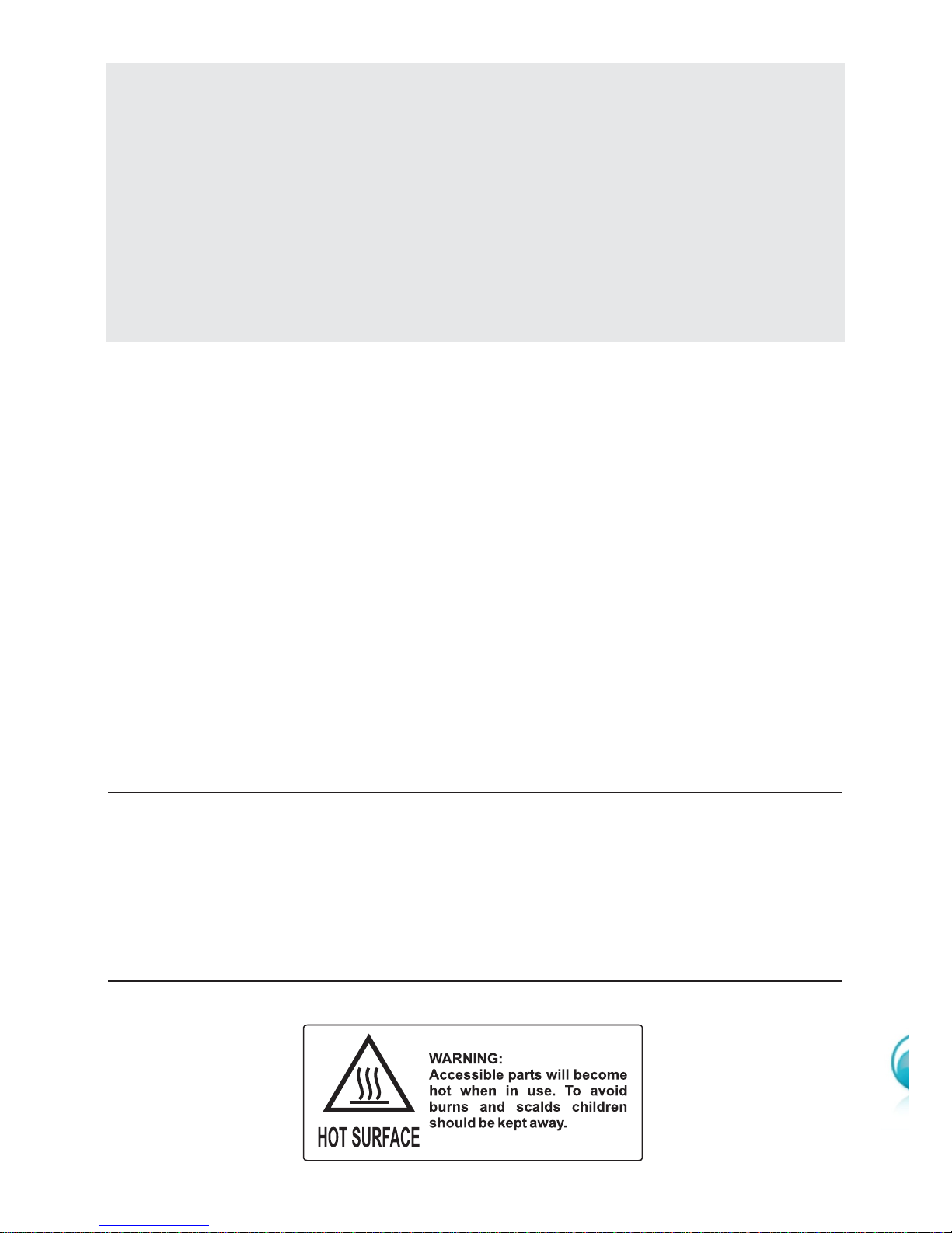
■ During and after use of the appliance, certain parts will become very hot. Do not touch hot
parts. Care should be taken to avoid touching heating elements inside the oven.
■ Keep children away from the appliance when it is in use.
■ Young children should be supervised to ensure that they do not play with the appliance.
■ Some appliances are supplied with a protective film on steel and aluminium parts. This film must
be removed before using the appliance.
■ Make sure that electrical cables connecting other appliances in the proximity of the cooker can-
not come into contact with the hob or become entrapped in the oven door.
■ Do not line the oven walls with aluminium foil. Do not place baking trays or the drip tray on the
base of the oven chamber.
■ WARNING When correctly installed, your product meets all safety requirements laid down for
this type of product category. However special care should be taken around the rear or the
underneath of the appliance as these areas are not designed or intended to be touched and
may contain sharp or rough edges, that may cause injury.
■ Fire risk! Do not store flammable material in the oven.
■ Always use oven gloves when removing the shelves and food trays from the oven whilst hot.
■ Do not hang towels, dishcloths or other items on the appliance or its handle – as this could be a
fire hazard.
■ Clean the oven regularly and do not allow fat or oils to build up in the oven base or tray.
Remove spillages as soon as they occur.
■ Do not stand on the open oven door.
■ Always stand back from the appliance when opening the oven door to allow steam and hot air
to escape before removing the food.
■ This appliance is for domestic use only.
■ Safe food handling: leave food in the oven for as short a time as possible before and after cook-
ing. This is to avoid contamination by organisms which may cause food poisoning. Take particular care during warmer weather.
■ The manufacturer declines all liability for injury to persons or damage to property caused by
incorrect or improper use of the appliance.
■ WARNING: Taking care NOT to lift the oven by the door handle.
■ IMPORTANT NOTE: This appliance shall not be used as a space heater, espe-
cially if installed in marine craft or caravans.

5
INSTALLATION
CAUTION:
■ This appliance must be installed in accordance with these installation
instructions.
■ This appliance shall only be serviced by authorized personnel.
■ This appliance is to be installed only by an authorised person.
■ Incorrect installation, for which the manufacturer accepts no responsibility,
may cause personal injury of damage.
■ Always disconnect the cooker from mains power supply before carrying out
any maintenance operations or repairs.
■ In the room where the cooker is installed, there must be enough air to
allow the gas to burn correctly, according to the current local regulations.
ELECTRICAL REQUIREMENTS
■ The appliance must be connected to the mains checking that the voltage corre-
sponds to the value given in the rating plate and that the electrical cable sections can withstand the load specified on the plate.
■ The plug must be connected to an earthed socket in compliance with safety
standards.
■ If the appliance is supplied without a plug, fit a standard plug which is suitable
for the power consumed by the appliance.
■ The appliance must be connected directly to the mains placing a two pole
switch with minimum opening between the contacts of 3 mm between the
appliance and the mains.
■ The power supply cable must not touch the hot parts and must be positioned so
that it does not exceed 50°C above ambient.
■ Once the appliance has been installed, the switch or socket must always be
accessible.
■
If the supply cord is damaged it must be replaced by the manufacturer or
it’s Service Agent or a similarly qualified person in order to avoid a hazard.
WARNING: This cooker must be connected to electrical supply using
V105 insulated cable.
N.B. The connection of the appliance to earth is mandatory.
If the installation requires alterations to the domestic electrical system call a qualified
electrician. He should also check that the socket cable section is suitable for the power
drawn by the appliance.
Appliance power rating:
230 V~ 2460 W (10.6 A)
240 V~ 2680 W (11.1 A)
Replacing the power cord must be done by a qualified electrician in accordance with the instructions supplied by the manufacturer and in compliance
with established electrical regulations.
6
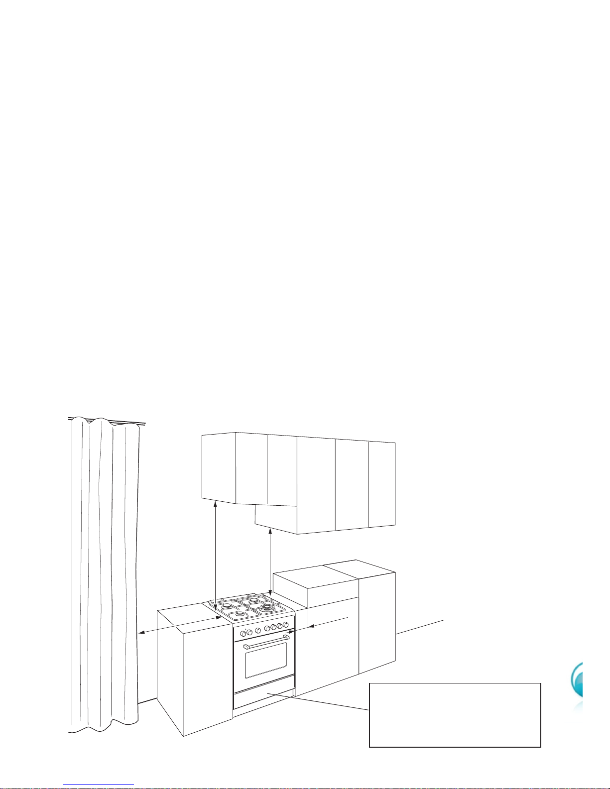
Figure 1
750 mm
500 mm
105 mm
450 mm
Cooker overall dimensions [mm]
• height: min 900 - max 915
• width: 600
• depth: 600
CLEARANCES
Installation clearances and protection of combustible surfaces shall comply with the
current local regulations eg. AG 601 (AS 5601) Gas Installations code.
Installation shall comply with the dimension in Fig. 1 bearing in mind that.
Overhead Clearances
In no case shall the clearances between the highest part of the cooker be less than
600 mm or for an overhead exhaust fan 750 mm. AII other downward facing combustible surfaces less than 600 mm above the cooker surface shall be protected for the
full width of the cooking surface in accordance with the standards noted above. In no
case shall the clearance be less than 450 mm.
Rear and Side Clearances
Where the dimensions from the periphery of the nearest burner to any vertical combustible surface is less than 200 mm the surface shall be protected in accordance with
the standards to a height of not less than 150 mm above the cooking surface for the
full width or depth of the cooking surface
Where the dimensions from the periphery of the nearest burner to any horizontal combustible surface is less than 200 mm, the horizontal surface shall be greater than
10 mm below the surface of the hob, or the horizontal surface requirement above.
Protection of combustible surfaces.
The standards above specify that where required protection shall ensure that the surface temperature of the combustible surface does not exceed 65 °C above room temperature.
If the cooker is located on a pedestal it is necessary to provide safety measures to prevent falling out.
7
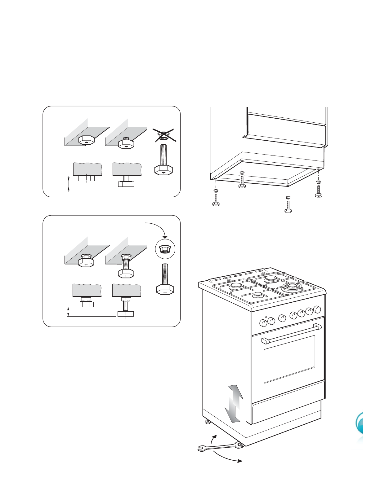
LEVELLING THE COOKER
The cooker is equipped with 4 levelling feet and may be levelled by screwing or
unscrewing the feet with a spanner (fig. 4).
It is important to observe the prescriptions of figures 2a, 2b, 3.
Supplied with the cooker
in a separate kit
+ 8 mm
+ 8
0
mm
+ 15 mm
Figure 2b
Figure 2a
Figure 3
Figure 4
8
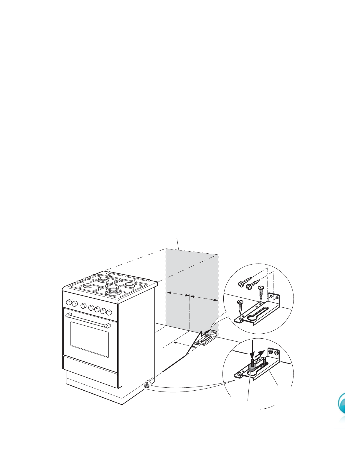
Figure 5
ANTI-TILT BRACKET
Important!
To restrain the appliance and prevent it tipping accidentally, the anti-tilt
bracket must be fitted according to the instructions below.
1. Drill four 8mm diameter holes for the fixing screws (two in the wall and two in the
floor - see Fig. 5) and insert the plastic plugs supplied.
Important! Before drilling the holes, check that you will not damage any
pipes or electrical wires.
2. Attach the anti-tilt bracket to the floor and rear wall using the four screws supplied,
as shown in Fig. 5.
3. After attaching the anti-tilt bracket securely, slide the cooker close to the anti-tilt
bracket and vertically fit the rear right foot into the circular opening of the bracket by
lifting the rear of the cooker. Then slide cooker into place.
Ensure that the rear right foot slides under the bracket, as shown in Fig. 5.
=
=
260
Dotted line showing the position
of the cooker when installed
Foot of cooker
Anti-tilt
bracket
Attaching the anti-tilt bracket and sliding the cooker into place
IMPORTANT NOTE: if necessary adjust the height of the feet to ensure the rear
right foot slides under the anti-tilt bracket.
9
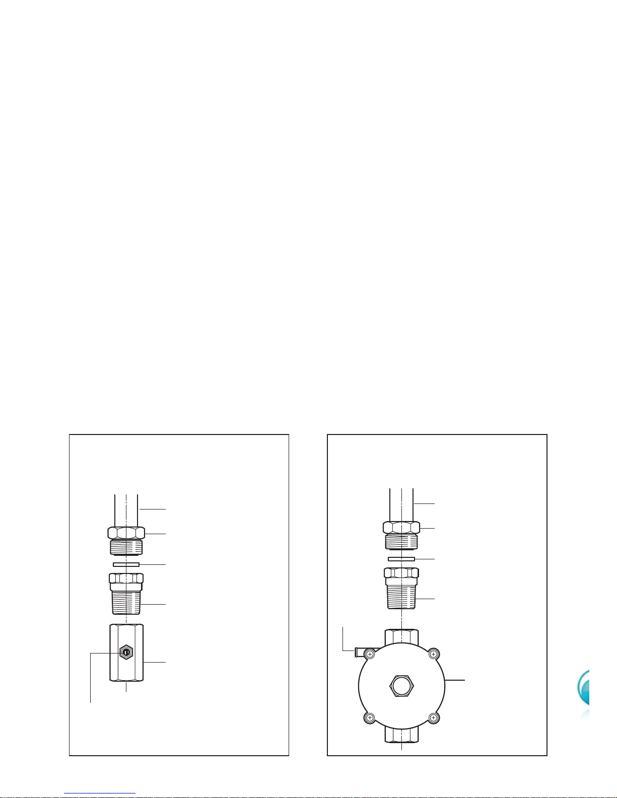
GAS SUPPLY:
■ The connection must be performed by an authorised person according to the
relevant standards.
■ Before connecting the appliance to the gas main, mount the brass conical adap-
tor onto the gas inlet pipe, upon which the gasket has been placed (figs. 6-7).
Conical adaptor and gasket are supplied with the appliance (packed with con-
version kit for use with Natural gas or ULPG).
■ This appliance is suitable for use with Natural Gas or ULPG. (Check the “gas
type” sticker attached to the appliance).
■ For Natural Gas models the gas supply is connected to the pressure regulator
which is supplied with the appliance (fig. 7). Adjust the regulator to obtain a test
point pressure of 1 kPa with the two semi-rapid (SR) burners operating at maximum.
■ For ULPG models the gas supply is connected to the test point adaptor which is
supplied with the appliance (fig. 6) and ensure that the supply pressure is regulated to 2.75 kPa.
■ The connection must be made at the rear of appliance (left or right); the pipe
does not cross the cooker.
■ The inlet not used must be closed off with the cap and sealing gasket supplied.
■ IMPORTANT: Use two spanners to tighten or loosen the connecting pipe (fig. 8)
Gas connection for
ULPG
Figure 7
Figure 6
Gas connection for
NATURAL GAS
Gas inlet pipe
Nipple
Gasket
Brass conical adaptor
(Thread tight: use
suitable seal)
Gas inlet pipe
Nipple
Gasket
Brass conical adaptor
(Thread tight: use
suitable seal)
Gas regulator
Test point adaptor
Test
point
Test
point
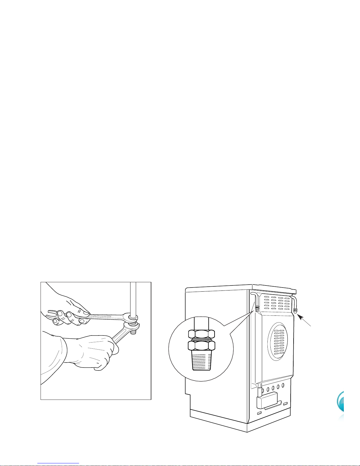
10
Plug
Figure 8
Figure 9
1. After connecting the gas supply, check the piping and connections for leaks using
a soap and water solution. The presence of bubbles indicates a leak, tighten or
replace connections as appropriate.
Warning: Do not use any naked flame to check for leaks.
2. Adjust the test point pressure or supply pressure to the value which is appropriate
for the gas type.
3. The operation of the appliance must be tested when installation is completed.
4. Turn on the appliance gas controls and light each burner individually and in combination. Check for a well defined blue flame without any yellow tipping. If any
abnormality is evident then check that the burner cap is located properly and the
injector nipple is aligned correctly.
5. Check the minimum burner setting by quickly rotating the gas control knob from
the maximum to the minimum position, the flame must not go out. If adjustment is
required carry out the “minimum burner setting adjustment" procedure described
6. If satisfacfory performance cannot be obtained, the installer shall check the installation and notify the local gas supply authority for a gas supply problem, or if it is an
appliance problem, our Customer Service Centre should be called to obtain the
nearest authorized Delonghi Service Agent.
WARNING, This appliance IS NOT SUITABLE for installation with a hose
assembly.
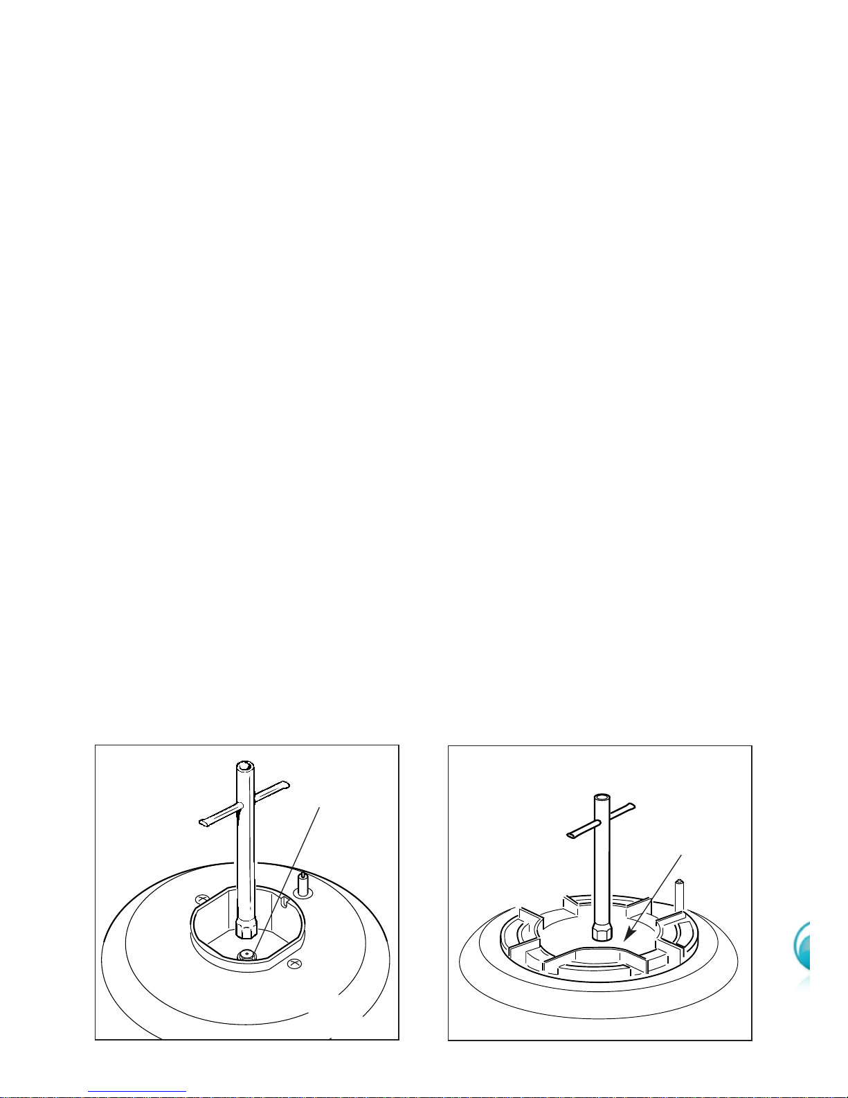
11
Figure 10
Figure 11
J
J
CONVERSION PROCEDURE (to convert to Natural gas or to ULPG)
REPLACING THE INJECTORS
This appliance is suitable for use with Natural gas or ULPG (check the “gas type” sticker
attached to the appliance). A label stating the type of gas used after replacing the
injectors must be attached at the rear of the appliance, in proximity of the gas inlet
connection. The nominal gas consumption and injector size details are provided in
table at page 13.
To replace the injectors proceed as follows:
■ Remove pan supports and burners from the cooktop.
■ Using a spanner, remove the injector J (figs. 10-11) and replace it with one
according to the gas type (see following tables - page 13).
■ Affix to the rear of the appliance, in proximity of the gas inlet connections, the
warning label (supplied with the conversion kit) stating that the cooker has
been converted for use with ULPG / Natural gas.
IMPORTANT
■ If the cooker is suitable for use with Natural gas and must be converted for use
with ULPG, before connecting to gas main remove the appliance gas regulator
and replace with test point adaptor (see figs. 6-7)
■ If the cooker is suitable for use with ULPG and must be converted for use with
Natural gas, before connecting to the gas main remove the appliance test point
adaptor and replace with gas regulator (see figs. 6-7).
NOTE:
Gas regulator and test point adaptor are supplied with the appliance (packed with
conversion kit)
The burners are designed so that regulation of primary air is not required.
 Loading...