

DeLonghi DE 60 E Installation And Care Manual

INSTALLATION and SERVICE INSTRUCTIONS
USE and CARE INSTRUCTIONS
distributed by
DèLonghi
Pty Ltd
DE 60 E
CERAMIC COOKER

2
Dear Customer,
Thank you for having purchased and given your
preference to our product.
The safety precautions and recommendations reported
below are for your own safety and that of others. They
will also provide a means by which to make full use of
the features offered by your appliance.
Please keep this booklet in a safe place. It may be
useful in future, either to yourself or to others in the
event that doubts should arise relating to its operation.
This appliance must be used only for the task it has
explicitly been designed for, that is for cooking
foodstuffs. Any other form of usage is to be considered
as inappropriate and therefore dangerous.
The manufacturer declines all responsibility in the
event of damage caused by improper, incorrect or
illogical use of the appliance or be faulty installation.
PRODUCT LABEL
Important:
This appliance is designed and manufactured solely for the cooking of domestic
(household) food and is not suitable for any non domestic application and therefore should not be used in a commercial environment.
The appliance guarantee will be void if the appliance is used within a non domestic environment i.e. a semi commercial, commercial or communal environment.

3
IMPORTANT PRECAUTIONS AND RECOMMENDATIONS FOR
USE OF ELECTRICAL APPLIANCES
Use of any electrical appliance implies the necessity to follow a series of fundamental
rules. In particular:
■ Never touch the appliance with wet hands or feet;
■ Do not operate the appliance barefooted;
■ The appliance is not intended for use by young children or infirm persons
without supervision;
■ Young children should be supervised to ensure they do not play with the
appliance.
The manufacturer cannot be held responsible for any damages caused by improper,
incorrect or illogical use of the appliance.
USING THE OVEN FOR THE FIRST TIME
You are advised to carry out the following operations:
■ Furnish the interior of the oven.
■ Switch the empty oven ON at maximum temperature for about two hours
to eliminate traces of grease and smell from the components.
■ Disconnect the appliance from the electric power supply and clean the
interior of the oven with a cloth soaked in water and neutral detergent
and dry thoroughly.
This cooker has been designed and constructed in accordance with the following
codes and specifications:
AS/NZS 60335-1 General Requirements for Domestic electrical appliances
AS/NZS 60335-2-6 Particular Requirements for Domestic electrical cooking appliances
AS/NSZ 1044 Electromagnetic Compatibility Requirements.

4
IMPORTANT PRECAUTIONS AND RECOMMENDATIONS
After having unpacked the appliance, check to ensure that it is not damaged.
In case of doubt, do not use it and consult your supplier or a professionally qualified technician.
Packing elements (i.e. plastic bags, polystyrene foam, nails, packing straps, etc.) should not be
left around within easy reach of children, as these may cause serious injuries.
■ Do not attempt to modify the technical characteristics of the appliance as this may become danger-
ous to use.
■ Do not carry out cleaning or maintenance operations on the appliance without having previously
disconnected it from the electric power supply.
■ After use, ensure that the knobs are in the off position.
■ The appliance is not intended for use by young children or infirm persons unless they have been
adequately supervised by a responsible person to ensure that they can use the appliance safely.
■ During and after use of the appliance, certain parts will become very hot. Do not touch hot parts.
Care should be taken to avoid touching heating elements inside the oven.
■ Keep children away from the appliance when it is in use.
■ Young children should be supervised to ensure that they do not play with the appliance.
■ Some appliances are supplied with a protective film on steel and aluminium parts. This film must be
removed before using the appliance.
■ Make sure that electrical cables connecting other appliances in the proximity of the cooker cannot
come into contact with the hob or become entrapped in the oven door.
■ Do not line the oven walls with aluminium foil. Do not place baking trays or the drip tray on the base
of the oven chamber.
■ WARNING When correctly installed, your product meets all safety requirements laid down for this
type of product category. However special care should be taken around the rear or the underneath
of the appliance as these areas are not designed or intended to be touched and may contain sharp
or rough edges, that may cause injury.
■ Fire risk! Do not store flammable material in the oven and in the drawer.
■ Always use oven gloves when removing the shelves and food trays from the oven whilst hot.
■ Do not hang towels, dishcloths or other items on the appliance or its handle – as this could be a fire
hazard.
■ Do not allow heavy or sharp objects to drop on the glass ceramic hob. If the hob is cracked or other-
wise damaged by falling objects etc., disconnect the electrical power cord and call Customer Service.
■ Do not scratch the hob with sharp objects. Don't use the hob as a work surface.
■ Clean the oven regularly and do not allow fat or oils to build up in the oven base or tray. Remove
spillages as soon as they occur.
■ Do not stand on the open oven door.
■ Always stand back from the appliance when opening the oven door to allow steam and hot air to
escape before removing the food.
■ This appliance is for domestic use only.
■ Safe food handling: leave food in the oven for as short a time as possible before and after cooking.
This is to avoid contamination by organisms which may cause food poisoning. Take particular care
during warmer weather.
■ The manufacturer declines all liability for injury to persons or damage to property caused by incorrect
or improper use of the appliance.
■ WARNING: Taking care NOT to lift the oven by the door handle.
■ IMPORTANT NOTE: This appliance shall not be used as a space heater, especial-
ly if installed in marine craft or caravans.

5
CAUTION:
■ This appliance must be installed in accordance with these installation
instructions.
■ This appliance shall only be serviced by authorized personnel.
■ This appliance is to be installed only by an authorised person.
■ Incorrect installation, for which the manufacturer accepts no responsibility,
may cause personal injury of damage.
■ Always disconnect the cooker from mains power supply before carrying out
any maintenance operations or repairs.
INSTALLATION
ELECTRICAL REQUIREMENTS
■ The appliance must be connected to the mains checking that the voltage corre-
sponds to the value given in the rating plate and that the electrical cable sections can withstand the load specified on the plate.
■ The appliance must be connected directly to the mains placing an two pole
switch with minimum opening between the contacts of 3 mm between the
appliance and the mains.
■ The power supply cable must not touch the hot parts and must be positioned so
that it does not exceed 75°C at any point.
■ Once the appliance has been installed, the switch must always be accessible.
■
If the supply cord is damaged it must be replaced by the manufacturer or
it’s Service Agent or a similarly qualified person in order to avoid a hazard.
N.B. The connection of the appliance to earth is mandatory.
If the installation requires alterations to the domestic electrical system call a qualified
electrician. He should also check that the electrical system is suitable for the power
drawn by the appliance.
Replacing the power cord must be done by a qualified electrician in
accordance with the instructions supplied by the manufacturer and in
compliance with established electrical regulations.
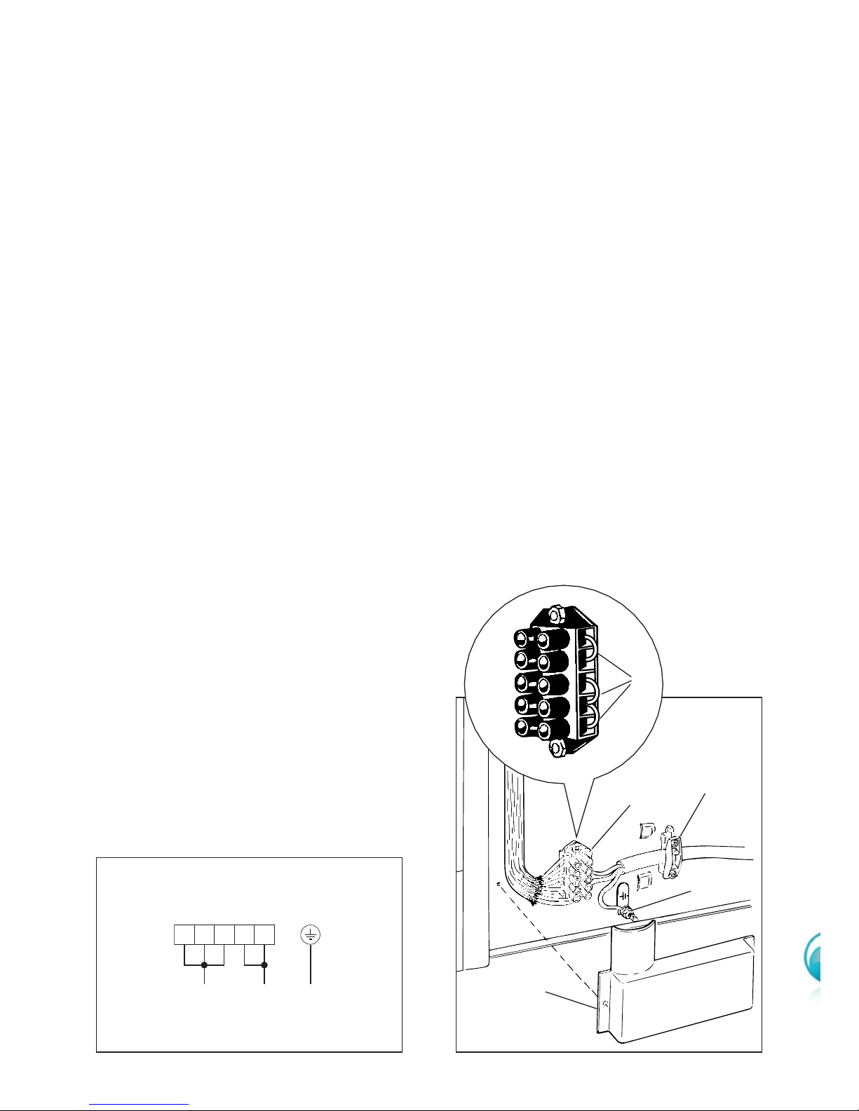
Figure 1
Figure 2
6
CONNECTING THE FEEDER CABLE
Important!
This cooker must be connected to the electricity supply only by an authorised person.
To connect the feeder cable to the cooker it is necessary to:
■ Remove the screws that hold shield A behind the cooker (fig. 2).
■ Fitted with a 5-pole terminal block, position the U bolts “C” onto terminal block “B”
according to the diagram in fig. 1.
■ Feed the supply cable through the cable clamp “D”. The supply cable must be of a
suitable size for the current requirements of the appliance; see the section “Feeder
cable section”.
■ Connect the phase wires to the terminal block “B” and the earth wire to the terminal
“PE” as shown in figure 2.
■ Take up any slack in the cable and secure with the cable clamp “D”.
■ Replace the cover “A”.
N.B. The earth conductor must be left about 3 cm longer than the others.
Voltage and power consumption
230 V~ 50 Hz 8700 W (37.8 A) (diversity not applied)
240 V~ 50 Hz 9500 W (39.5 A) (diversity not applied)
Feeder cable section
This cooker must be connected to
electrical supply using V105 insulated cable.
230-240 V~ 3 x 4 mm
2
(*)
(*)
Connection with wall box connection.
- Diversity factor applied
- A diversity factor may be applied to
the total loading of the cooker only
by a suitably qualified person.
B
A
543
2
1
C
B
PE
D
PEL1 N (L2)
12345
230-240 V~
7
500 mm
minimum
50 mm
650 mm
450 mm
IMPORTANT
– The appliance should be installed by a registered electrician in compliance with the
current electrical regulations and in observation of the instructions supplied by the
manufacturer.
Failure to comply with this condition will render the guarantee invalid.
– Always disconnect the cooker from mains power supply before carrying out any
maintenance operations or repairs.
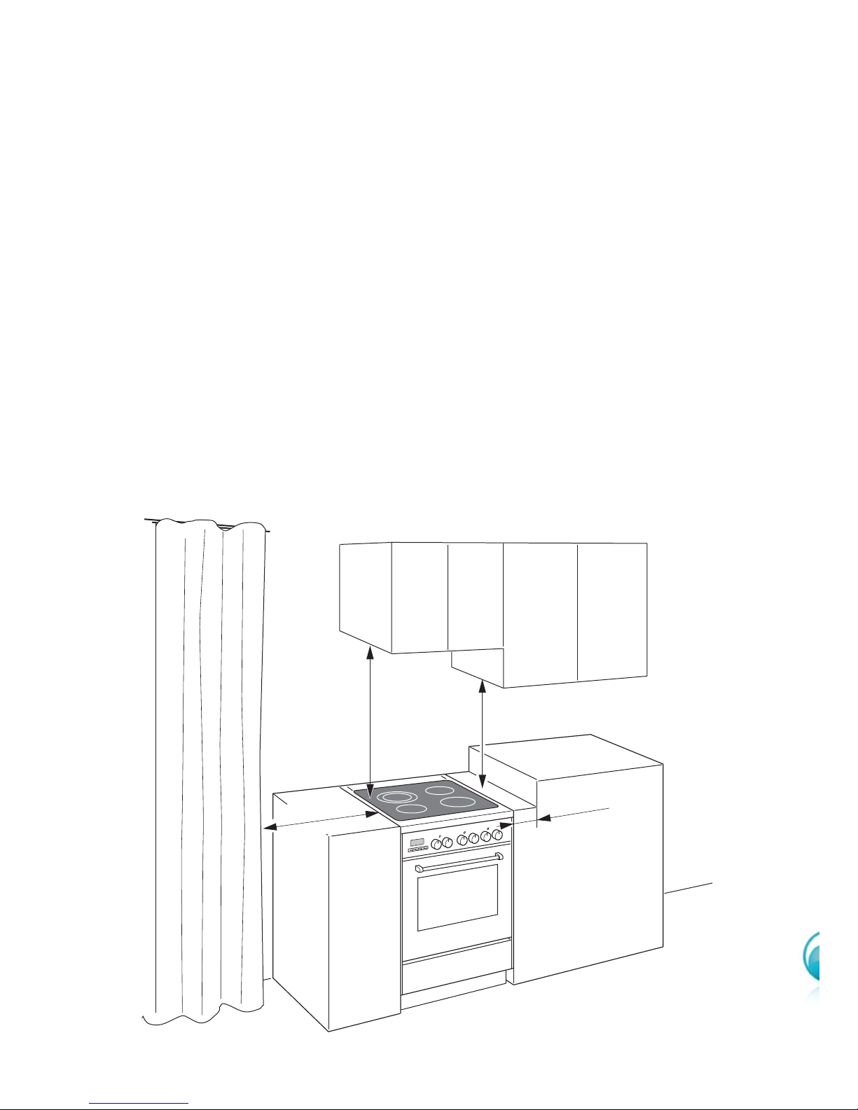
LOCATION
The cooker can be installed in a cabinet.
The cooker must be installed no less than 50 mm away from any side wall which
exceed the height of the cooktop;
The appliance must be housed in heat resistant units.
The walls of the units must be capable of resisting temperatures of 75 °C
above room temperature.
Do not install the appliance near inflammable materials (eg. curtains).
Figure 3
8
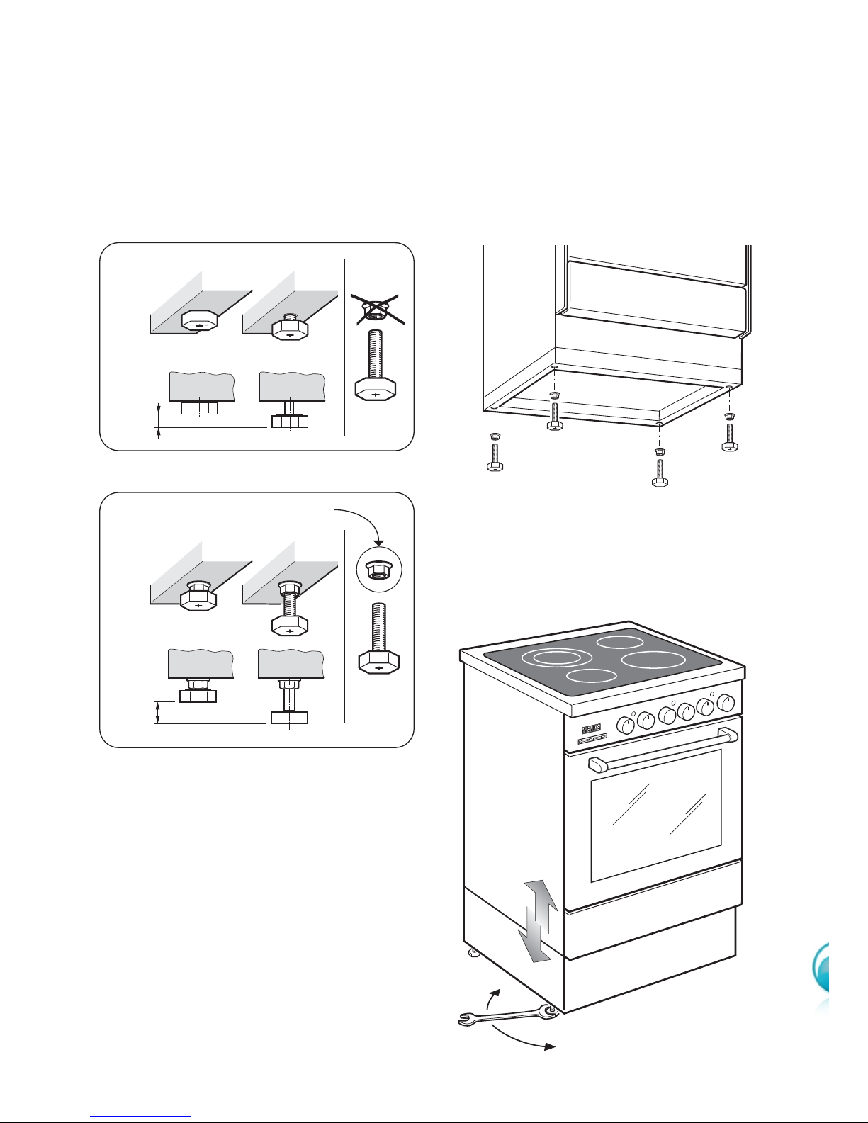
LEVELLING THE COOKER
The cooker is equipped with 4 levelling feet and may be levelled by screwing or
unscrewing the feet with a spanner (fig. 6).
It is important to observe the prescriptions of figures 4a, 4b.
Supplied with the cooker
in a separate kit
A
U
T
O
+ 8 mm
+ 8
0
mm
+ 15 mm
Figure 4b
Figure 4a
Figure 5
Figure 6
9
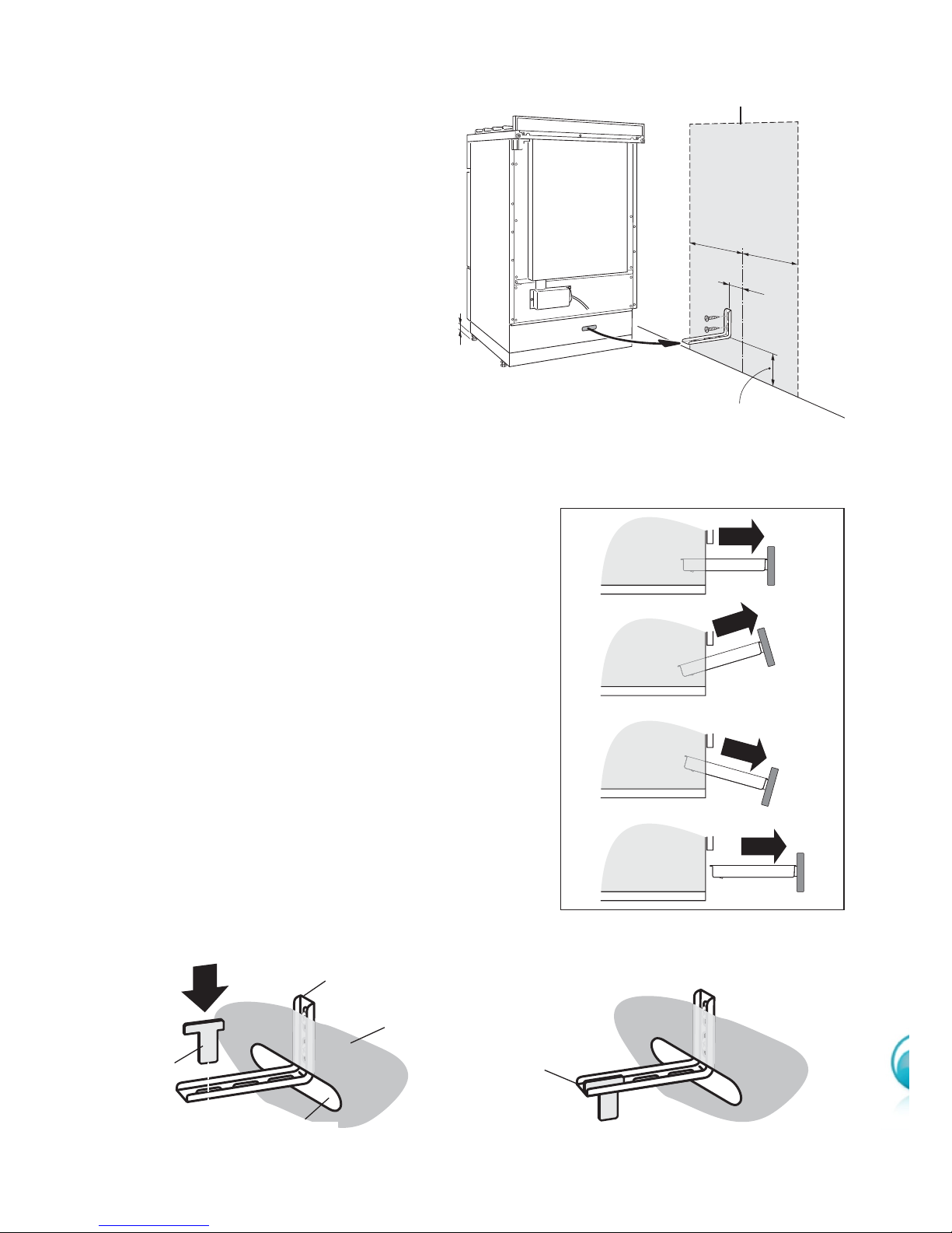
ANTI-TILT BRACKET
Important!
To restrain the appliance and prevent it tipping accidentally, fit a
bracket to its rear to fix it securely
to the wall. Make sure you also fit
the supplied lock pin to the anti-tilt
bracket.
To fit the anti-tilt bracket:
1. After you have located where the
cooker is to be positioned, mark on
the wall the place where the two
screws of the anti-tilt bracket have to
be fitted. Please follow the indications given in Fig.7a.
2. Drill two 8 mm diameter holes in the
wall and insert the plastic plugs supplied.
Important!
Before drilling the holes, check that you will
not damage any pipes or electrical wires.
3. Loosely attach the anti-tilt bracket with the two
screws supplied.
4. Move the cooker to the wall and adjust the
height of the anti-tilt bracket so that it can
engage in the slot on the cooker’s back, as
shown in Fig. 7a.
5. Tighten the screws attaching the anti-tilt bracket.
6. Push the cooker against the wall so that the antitilt bracket is fully inserted in the slot on the cooker’s back.
7. Access the bracket and fit the lock pin:
• Remove the drawer (Fig. 7b).
• Fit the lock pin through the bracket, as shown
(Fig. 7c).
• Refit the drawer.
57
=
=
0
+15
1
2
3
4
1
2
Figure 7b
Removing the drawer
Figure 7c
Fitting the lock pin through
the bracket
Figure 7a
Fitting the anti-tilt bracket
Lock pin
correctly
fitted
Lock pin
Slot on the
cooker’s back
Cooker’s
back
Anti-tilt bracket
attached on the
rear wall
Dotted line showing the position of
the cooker when installed
min 95 - max 110
(depending on feet
height adjustment)
10
USE and CARE
CAUTION:
■ This appliance must be used only for the task it has explicitly been designed for,
that is for domestic cooking of foodstuffs. Any other form of usage is to be considered as inappropriate and therefore dangerous.
■ Do NOT place combustible materials or products on this appliance at any time.
Figure 8
USING THE OVEN FOR THE FIRST TIME
Operate as follows:
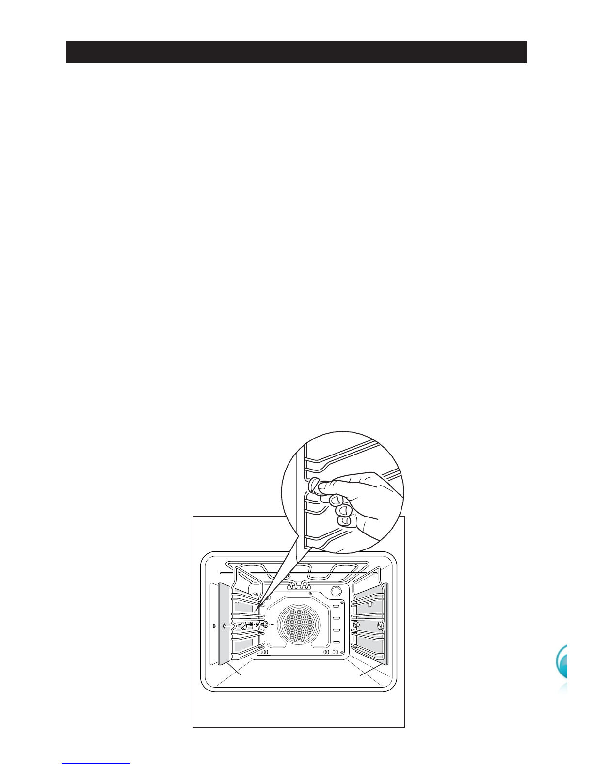
■ Assemble the wire racks on the oven walls using the 2 screws (fig. 8) interposing
the catalytic panels A with the arrow up (fig. 8).
■ Slide in the grease filter on the back of the oven as in Fig. 11.
■ Slide in, on the guides, the shelf and the tray (fig. 9). The rack must be fitted so
that the safety catch, which stops it sliding out, faces the inside of the oven.
A A
11
Figure 11
Figure 9
Figure 10
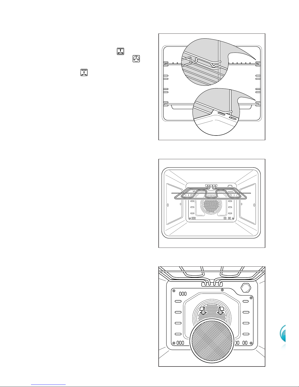
■ To eliminate traces of grease in
manufacture it is necessary to preheat the oven at the maximum temperature:
• For 60 minutes in the position, for 30 minutes in the
position and for another 15 minutes in the position.
■ Unscrew the fixing screws and slide
off the wire racks and the catalytic
liners to the oven wall as in fig. 8.
The grill is secured to the rear wall
of the oven on a hinge system that
allows it to be lowered to allow
proper access when cleaning the
oven ceiling (fig. 10).
■ Clean the inside of the oven with a
cloth soaked in water and neutral
detergent and dry thoroughly.
GREASE FILTER
■ A special screen is provided at the
back of the oven to catch grease
particles, mainly when meat is
being roasted fig. 11).
■ Clean the filter after any cooking!
The grease filter can be removed
for cleaning and should be
washed regularly in hot soapy
water (fig. 11).
■ Always dry the filter properly
before fitting it back into the oven.
CAUTION: When baking pastry etc. this
filter should be removed.
12
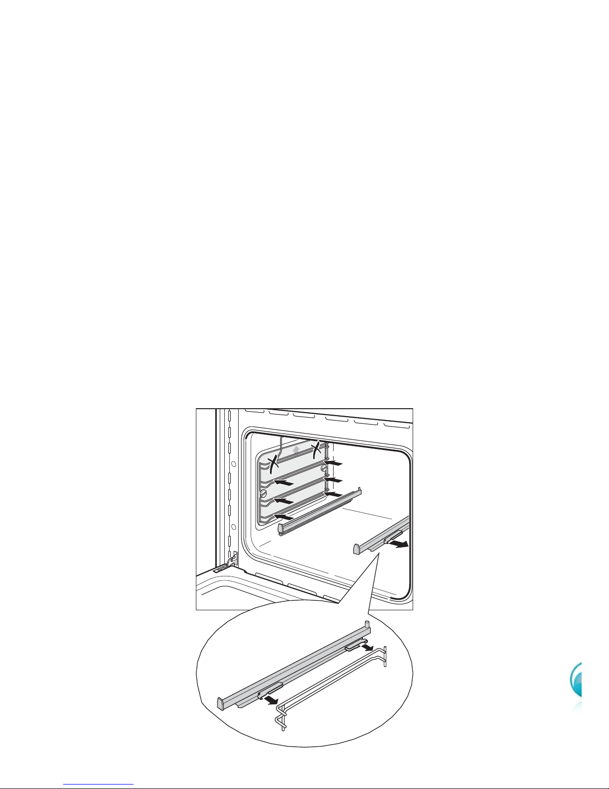
TELESCOPIC SLIDING SHELF SUPPORTS
The telescopic sliding shelf supports make it safer and easier to insert and remove the
oven shelves and trays. They stop when they are pulled out to the maximum position.
Important! When fitting the sliding shelf supports, make sure that you fit:
■ The slides to the top wire of a rack. They do not fit on the lower wire.
■ The slides so that they run out towards the oven door.
■ Both sides of each pair of shelf slides.
■ Both sides on the same level.
■ Note: you cannot fit the sliding shelf supports to the top shelf position (fig. 12).
To fix the sliding shelf support onto the side racks:
■ Screw the side rack onto the oven wall interposing the catalytic panels (Fig. 8).
■ Fit the sliding shelf support onto the top wire of a rack and press (Fig. 12). You will
hear a click as the safety locks clip over the wire.
Left
Right
Figure 12
13
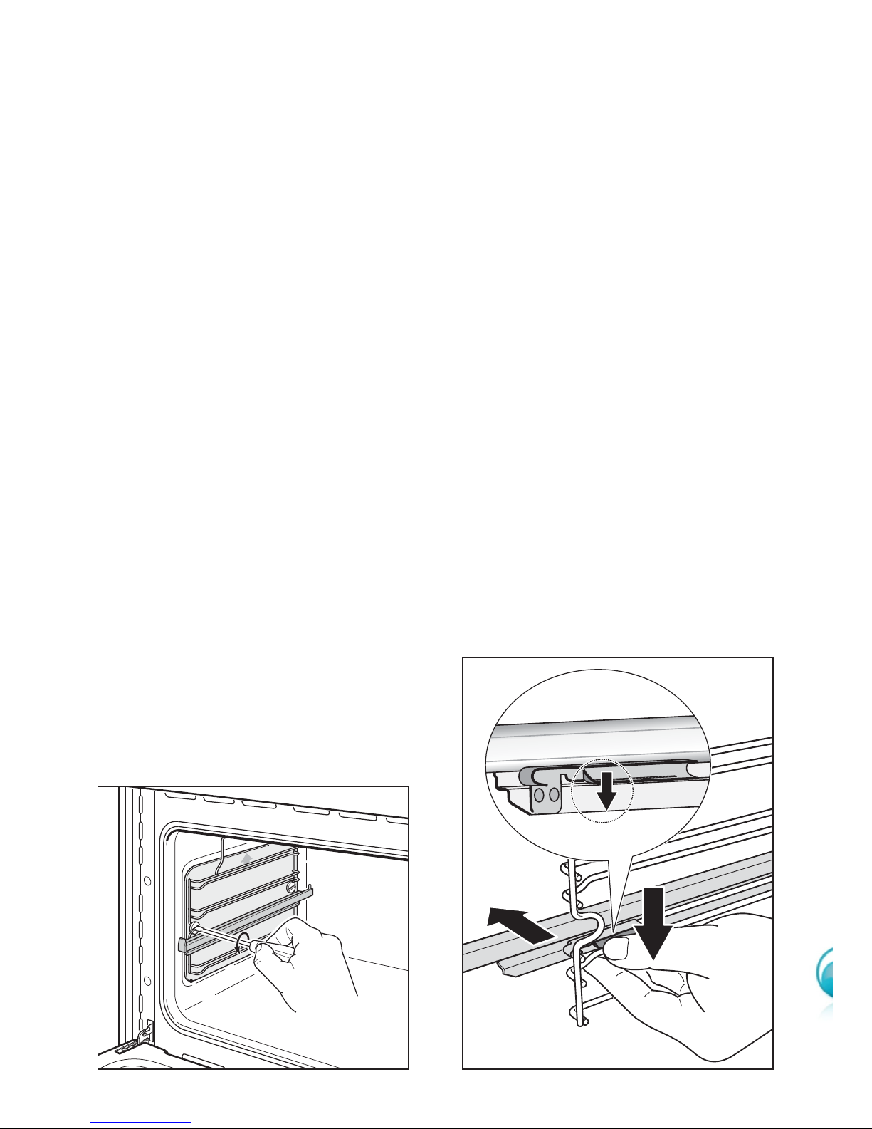
To remove the telescopic sliding shelf supports:
– Remove the side racks and the catalytic liners by unscrewing the fixing screws
(Fig. 13).
– Lay down the telescopic sliding shelf support and side racks, with the telescopic slid-
ing shelf support underneath.
– Find the safety locks. These are the tabs that clip over the wire of the side rack (arrow
1 in Fig. 14).
– Pull the safety locks away from the wire to release the wire (arrow 2 in Fig. 14).
1
2
1
Cleaning the sliding shelf supports
– Wipe the supports with a damp cloth and a mild detergent only.
– Do not wash them in the dishwasher, immerse them in soapy water, or use oven
cleaner on them.
Figure 14
Figure 13
14
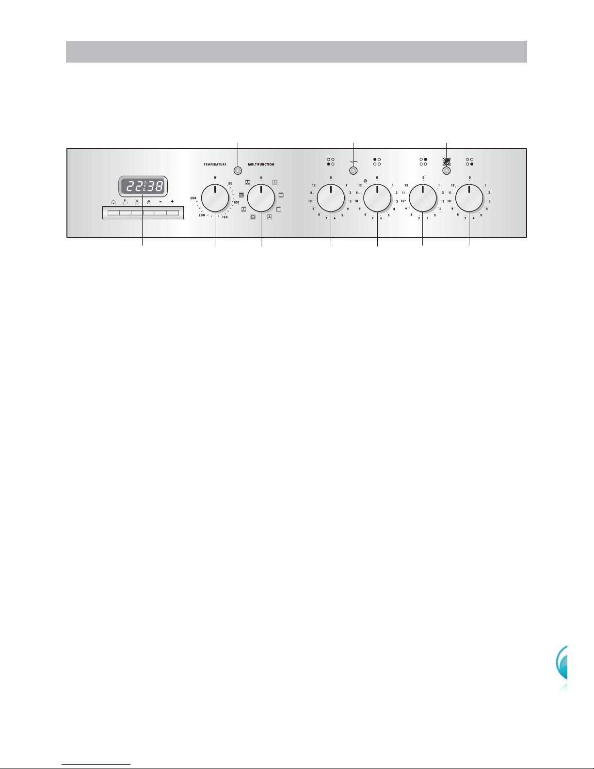
CONTROL PANEL
A
U
T
O
P
7564321
CONTROL PANEL - Controls description
1. Front right cooking zone control knob
2. Rear right cooking zone control knob
3. Rear left cooking zone control knob
4. Front left cooking zone control knob
5. Multifunction oven switch knob
6. Multifunction oven thermostat knob
7. Electronic programmer
Pilot lamps:
8. Cooktop element hot surface indicator light
9. Cooktop element ON indicator light
10. Oven thermostat indicator light
Figure 15
10 9 8
Please note: This appliance incorporates a safety cooling fan which you will hear
operating whenever the oven or grill are in use. This fan is to reduce the external
temperature of the appliance and cool the internal components.
 Loading...