

Page 1
Dell™ XPS™ 430 Service Manual
Technical Overview
Before You Begin
Removing the Computer Cover
Replacing Memory Module(s)
Replacing PCI and PCI Express Cards
Replacing Drives
Replacing Fans
Model DC01L
Replacing the Front I/O Panel
Replacing the Processor
Replacing the System Board
Replacing the Power Supply
Replacing the Battery
Replacing the Computer Cover
System Setup
Notes, Notices, and Cautions
NOTE: A NOTE indicates important information that helps you make better use of your
computer.
NOTICE: A NOTICE indicates either potential damage to hardware or loss of data and tells you how to avoid the
problem.
CAUTION: A CAUTION indicates a potential for property damage, personal injury, or
death.
Information in this document is subject to change without notice.
© 2008 Dell Inc. All rights reserved.
Reproduction of these materials in any manner whatsoever without the written permission of Dell Inc. is strictly forbidden.
Trademarks used in this text: Dell, the DELL logo, and XPS are trademarks of Dell Inc.; Intel and Intel SpeedStep are either trademarks or registered
trademarks of Intel Corporation in the U.S. and other countries; Microsoft and Windows are either trademarks or registered trademarks of Microsoft
Corporation in the United States and/or other countries.
Other trademarks and trade names may be used in this document to refer to either the entities claiming the marks and names or their products. Dell
Inc. disclaims any proprietary interest in trademarks and trade names other than its own.
August 2008 Rev. A00
Page 2
Back to Contents Page
Technical Overview
Dell™ XPS™ 430 Service Manual
Inside View of Your Computer
System Board Components
CAUTION: Before working inside your computer, read the safety information that shipped with your
computer. For additional safety best practices information, see the Regulatory Compliance Homepage at
www.dell.com/regulatory_compliance.
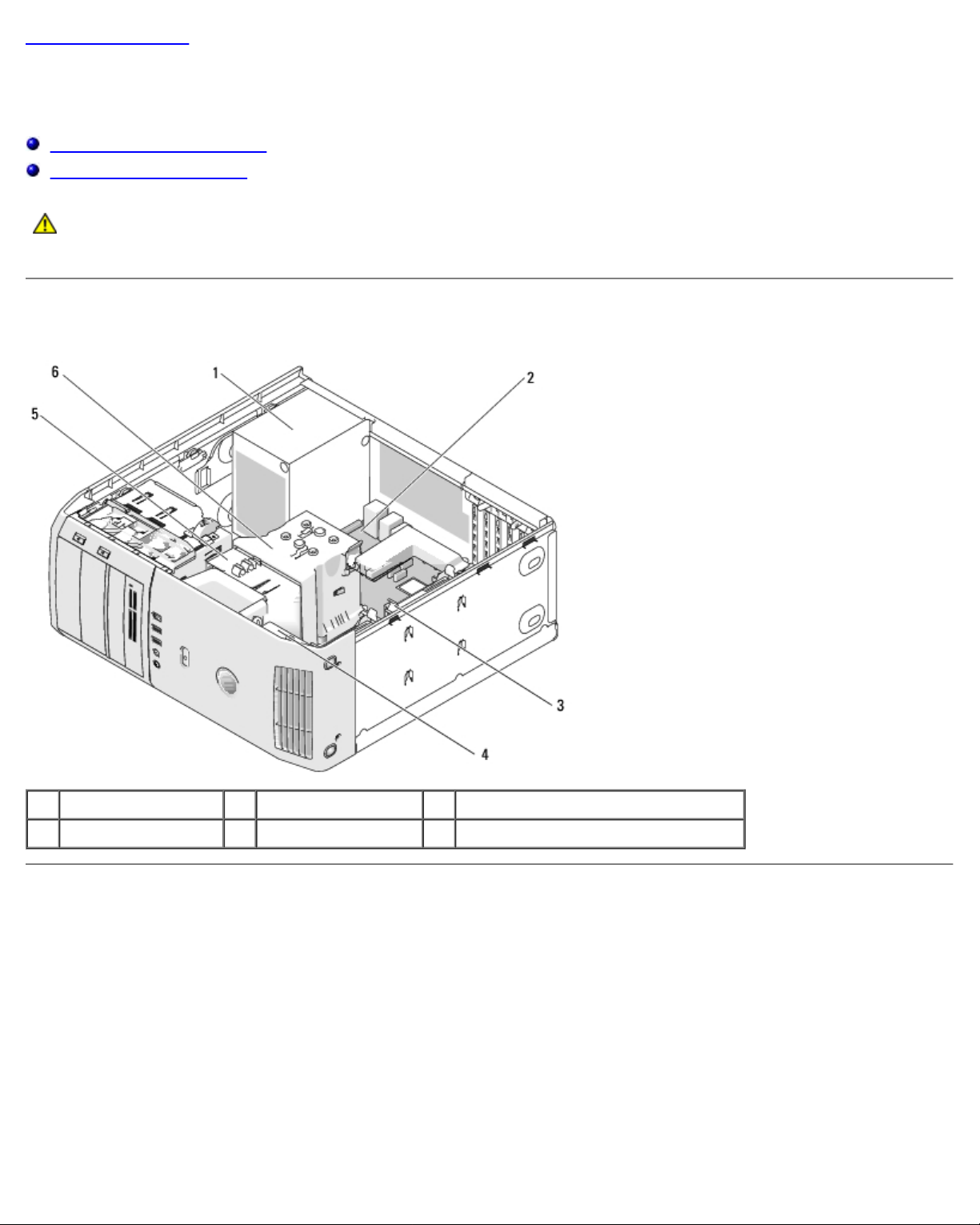
Inside View of Your Computer
1 power supply 2 system board 3 hard drive (2)
4 card fan 5 processor fan 6 processor airflow shroud
System Board Components
Page 3
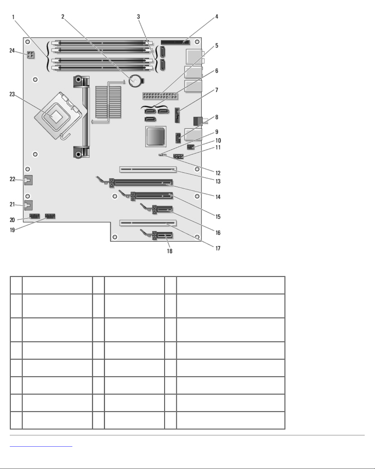
1 memory module
connectors (1, 2, 3, 4)
2 battery socket
(BATTERY)
3 SATA connectors (2) (SATA0,
SATA1)
4 front panel I/O
connector
7 Hard drive activity light
connector
10 S/PDIF connector 11 IEEE 1394
13 PCI card connector 14 PCI Express x16
16 PCI Express x1 card
connector
19 front USB connector
(USB1)
22 Processor fan
connector (FAN_CPU)
Back to Contents Page
5 main power
connector
(POWER)
8 FlexBay USB
connector
(FLEXBAY)
connector
card connector
17 PCI card connector 18 PCI Express x1 card connector
20 front USB
connector (USB2)
23 processor
connector
6 SATA connectors (3) (SATA2,
SATA3, SATA4)
9 clear CMOS jumper (RTCRST)
12 password jumper (PSWD)
15 PCI Express x8 card connector
(x4 electrical)
21 rear fan connector or card cage fan
connector (FAN_CARD_CAGE)
24 processor power connector
(12VPOWER)
Page 4

Page 5
Back to Contents Page
Before You Begin
Dell™ XPS™ 430 Service Manual
Technical Specifications
Recommended Tools
Turning Off Your Computer
Safety Instructions
This chapter provides procedures for removing and installing the components in your computer. Unless otherwise noted, each
procedure assumes that the following conditions exist:
You have performed the steps in Turning Off Your Computer and Safety Instructions.
You have read the safety information that shipped with your computer.
A component can be replaced or—if purchased separately—installed by performing the removal procedure in reverse
order.
Technical Specifications
For information on technical specifications of your computer, see the Quick Reference Guide that shipped with your computer
or see the Dell Support website at support.dell.com.
Recommended Tools
The procedures in this document may require the use of a small Phillips screwdriver size #2.
Turning Off Your Computer
NOTICE: To avoid losing data, save and close all open files and exit all open programs before you turn off your
computer.
1. Shut down the operating system.
2. Ensure that the computer and all attached devices are turned off. If your computer and attached devices did not
automatically turn off when you shut down your operating system, press and hold the power button for about 4
seconds to turn them off.
Safety Instructions
Use the following safety guidelines to help protect your computer from potential damage and to help to ensure your own
personal safety.
CAUTION: Before working inside your computer, read the safety information that shipped with your
computer. For additional safety best practices information, see the Regulatory Compliance Homepage at
www.dell.com/regulatory_compliance.
Page 6

NOTICE: Only a certified service technician should perform repairs on your computer. Damage due to servicing that is
not authorized by Dell™ is not covered by your warranty.
NOTICE: When you disconnect a cable, pull on its connector or on its pull-tab, not on the cable itself. Some cables have
connectors with locking tabs; if you are disconnecting this type of cable, press in on the locking tabs before you
disconnect the cable. As you pull connectors apart, keep them evenly aligned to avoid bending any connector pins.
Also, before you connect a cable, ensure that both connectors are correctly oriented and aligned.
NOTICE: To avoid damaging the computer, perform the following steps before you begin working inside the computer.
1. Ensure that the work surface is flat and clean to prevent the computer cover from being scratched.
2. Turn off your computer (see Turning Off Your Computer
NOTICE: To disconnect a network cable, first unplug the cable from your computer and then unplug the cable from the
network device.
3. Disconnect all telephone or network cables from the computer.
4. Disconnect your computer and all attached devices from their electrical outlets.
5. Press and hold the power button while the system is unplugged to ground the system board.
NOTICE: Before touching anything inside your computer, ground yourself by touching an unpainted metal surface, such
as the metal at the back of the computer. While you work, periodically touch an unpainted metal surface to dissipate
static electricity, which could harm internal components.
Back to Contents Page
).
Page 7
Back to Contents Page
Removing the Computer Cover
Dell™ XPS™ 430 Service Manual
CAUTION: Before working inside your computer, read the safety information that shipped with your
computer. For additional safety best practices information, see the Regulatory Compliance Homepage at
www.dell.com/regulatory_compliance.
CAUTION: To guard against likelihood of electric shock, laceration by moving fan blades or other
unexpected injuries, always unplug your computer from the electrical outlet before removing the cover.
NOTICE: Ensure that sufficient space exists to support the system with the cover removed—at least 30 cm (1 ft.) of
desktop space.
1. Follow the procedures in Before You Begin
2. If you have installed a security cable, remove it from the security cable slot.
NOTICE: Ensure that you are working on a level, protected surface to avoid scratching either the computer or the
surface on which it is resting.
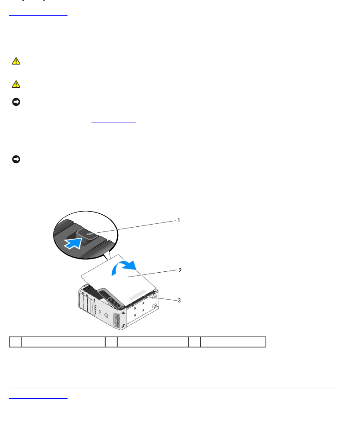
3. Lay your computer on its side with the computer cover facing up.
4. Pull back the cover release latch on the top panel.
.
1 cover release latch 2 computer cover 3 hinge tabs (3)
5. Grip the sides of the computer cover and pivot the cover up.
6. Lift the cover away and set it aside in a secure location.
Back to Contents Page
Page 8
Back to Contents Page
Replacing Memory Module(s)
Dell™ XPS™ 430 Service Manual
CAUTION: Before working inside your computer, read the safety information that shipped with your
computer. For additional safety best practices information, see the Regulatory Compliance Homepage at
www.dell.com/regulatory_compliance.
1. Follow the procedures in Before You Begin
2. Remove the computer cover (see Removing the Computer Cover).
3. Locate the memory modules on the system board (see System Board Components).
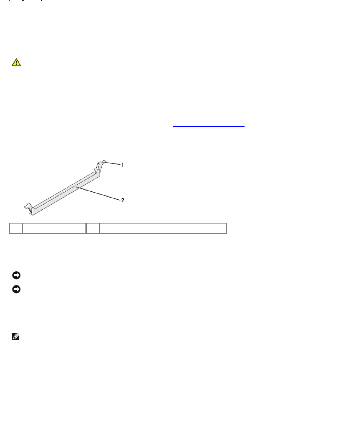
4. Press out the securing clip at each end of the memory module connector.
1 securing clip 2 memory module connector
5. Grasp the module and pull it upwards.
.
If the module is difficult to remove, gently ease the module back and forth to remove it from the connector.
NOTICE: Do not install ECC memory modules.
NOTICE: If you remove your original memory modules from the computer during a memory upgrade, keep them
separate from any new modules that you may have, even if you purchased the new modules from Dell™. If possible,
do not pair an original memory module with a new memory module. Otherwise, your computer may not start properly.
The recommended memory configurations are:
A pair of matched memory modules installed in DIMM connectors 1 and 2 or
a pair of matched memory modules installed in DIMM connectors 1 and 2 and another matched pair installed in DIMM
connectors 3 and 4.
NOTE: If you install mixed pairs of PC3-8500 (DDR3 1066-MHz) and PC3-10600 (DDR3 1333-MHz) memory, the
modules function at the speed of the slowest module installed.
Page 9
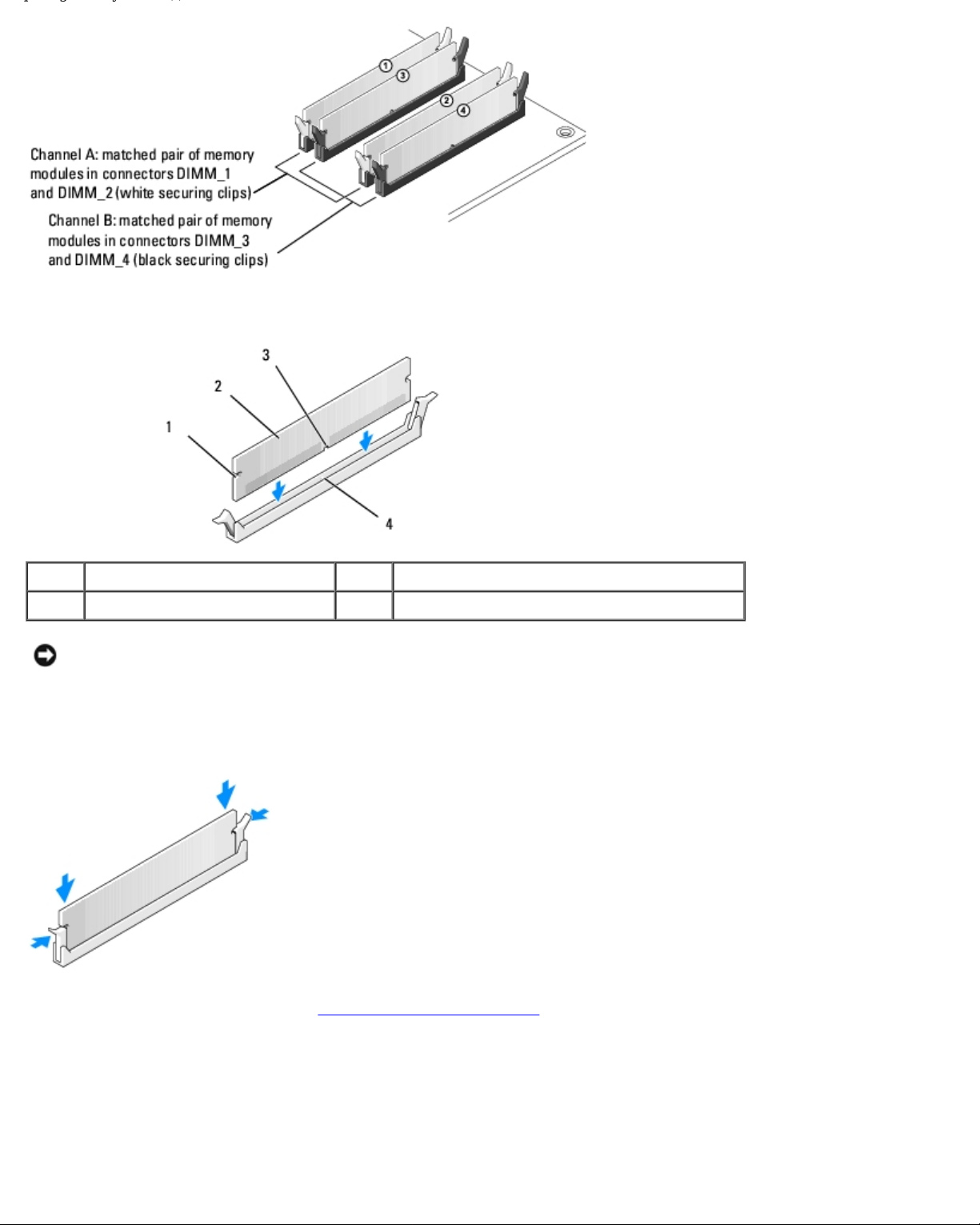
6. Align the notch on the bottom of the module with the tab in the connector.
1 cutouts (2) 2 memory module
3 notch 4 tab
NOTICE: To avoid damage to the memory module, press the module straight down into the connector while you apply
equal force to each end of the module.
7. Insert the module into the connector until the module snaps into position.
If you insert the module correctly, the securing clips snap into the cutouts at each end of the module.
8. Replace the computer cover (see Replacing the Computer Cover).
9. Connect your computer and devices to electrical outlets, and then turn them on.
10. If a message appears stating that memory size has changed, press <F1> to continue.
11. Log on to your computer.
Page 10

12. Right-click the My Computer icon, then click Properties.
13. Click the General tab.
14. To verify that the memory is installed correctly, check the amount of memory (RAM) listed.
Back to Contents Page
Page 11
Back to Contents Page
Replacing PCI and PCI Express Cards
Dell™ XPS™ 430 Service Manual
Removing PCI and PCI Express Cards
Installing PCI and PCI Express Cards
Configuring Your Computer After Removing or Installing PCI and PCI Express Cards
CAUTION: Before working inside your computer, read the safety information that shipped with your
computer. For additional safety best practices information, see the Regulatory Compliance Homepage at
www.dell.com/regulatory_compliance.
Removing PCI and PCI Express Cards
1. Follow the procedures in Before You Begin.
2. Uninstall the card's driver and software from the operating system. For more information, see the Quick Reference
Guide.
3. If necessary, disconnect any external cables connected to the card.
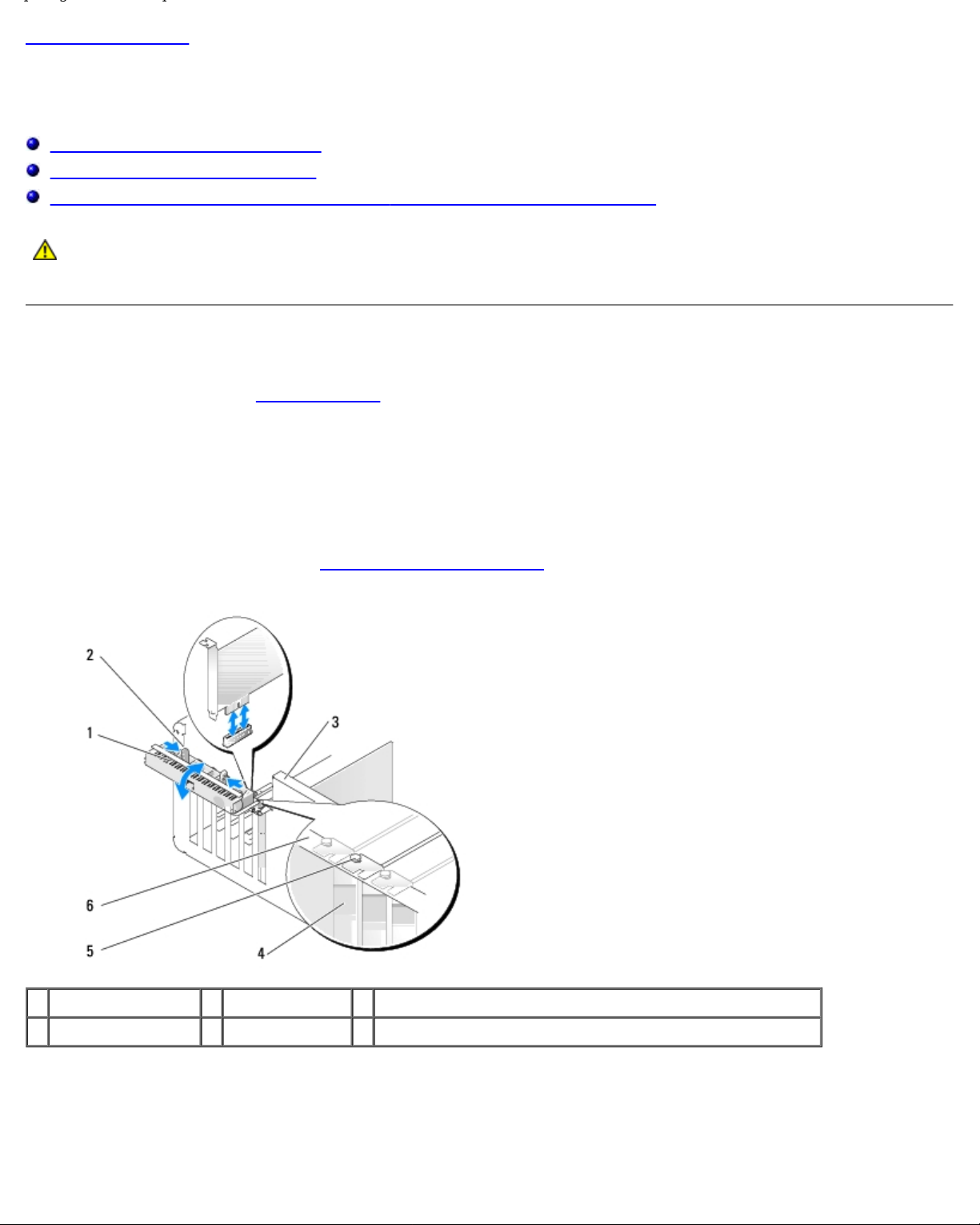
4. Remove the computer cover (see Removing the Computer Cover
).
1 card retention door 2 release tabs (2) 3 lever on chassis wall (may not be present on all computers)
4 filler bracket 5 alignment guide 6 alignment bar
5. If present on your computer, rotate the lever on the chassis wall upward.
6. Press the two release tabs on the card retention door towards each other and pivot the door open. The door is hinged
and remains in the open position.
Page 12
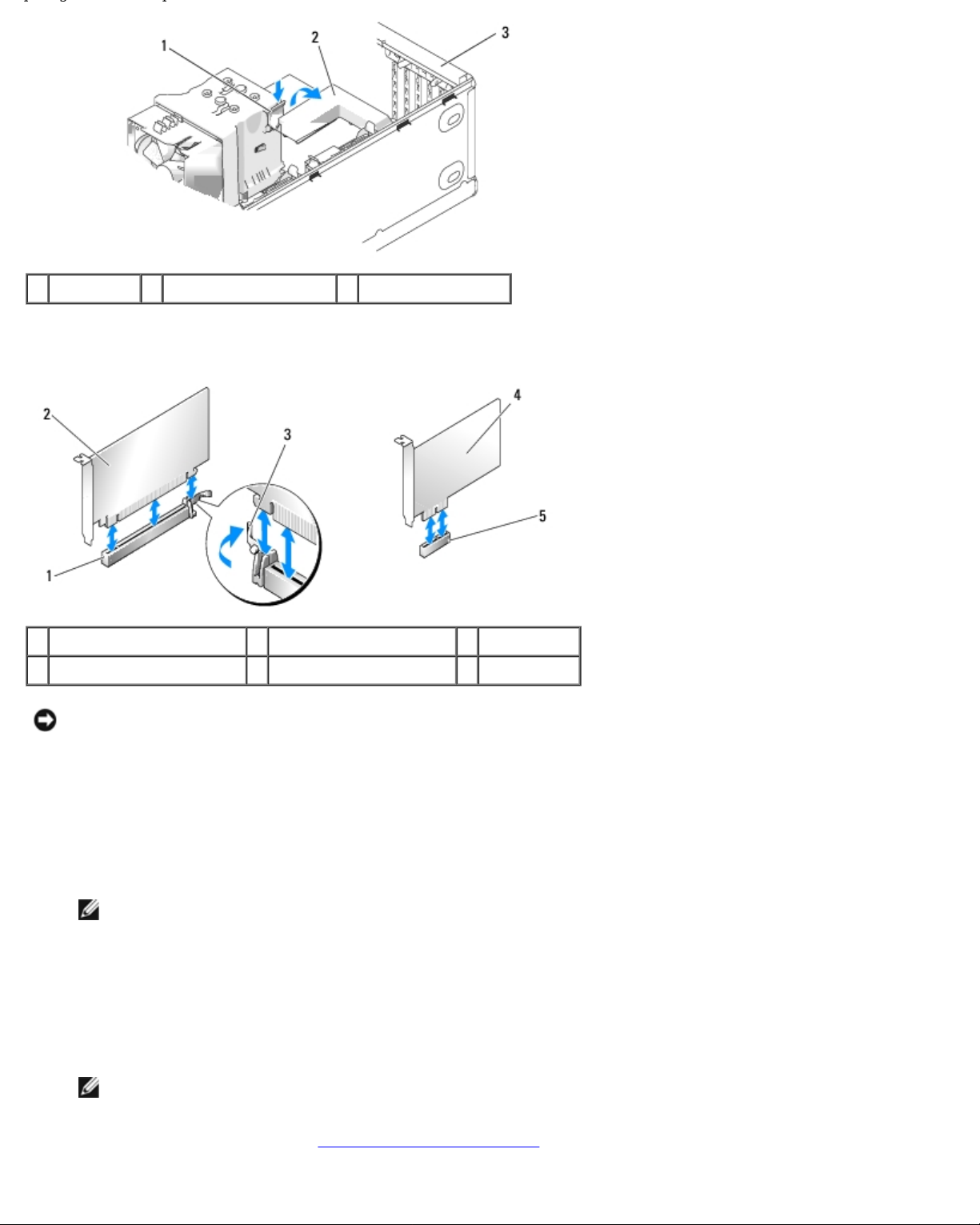
1 release tab 2 card retention bracket 3 card retention door
7. If your computer has a card retention bracket to secure the x16 card, press the release tab downward gently, and then
pivot the bracket upward to access the card slots.
1 PCI Express x16 card slot 2 PCI Express x16 card 3 securing tab
4 PCI Express x1 card 5 PCI Express x1 card slot
NOTICE: Ensure that you release the securing tab to unseat the card. If the card is not removed correctly, the system
board may be damaged.
8. If you are removing a PCI Express card, press the securing tab on the card slot to remove the card.
9. If you are removing the card permanently, install a filler bracket in the empty card-slot opening.
If you need a filler bracket, contact Dell (see "Contacting Dell" in the Quick Reference Guide).
NOTE: Installing filler brackets over empty card-slot openings is necessary to maintain FCC certification of the
computer. The brackets also keep dust and dirt out of your computer.
10. Push the card retention bracket back into its original position; push the tip of the bracket so the release tab clicks into
place.
11. Close the card retention door to secure the card(s).
NOTE: For full-length PCI-E cards, if a "piano" bracket is present on your computer you need to rotate it down
into place.
12. Replace the computer cover (see Replacing the Computer Cover
).
Page 13

13. Connect the computer and devices to electrical outlets, and then turn them on.
14. To complete the removal procedure, see Configuring Your Computer After Removing or Installing PCI and PCI Express
Cards.
Installing PCI and PCI Express Cards
1. Follow the procedures in Before You Begin.
2. Remove the computer cover. See Removing the Computer Cover.
3. If present on your computer, rotate the lever on the chassis wall upward.
4. Press the two release tabs on the card retention door towards each other and pivot the door open. The door is hinged
and remains in the open position.
5. If your computer includes a card retention bracket to secure the x16 card, press the release tab downward gently and
then pivot the bracket upward to access the card slots.
6. If you are installing a new card, remove the filler bracket to create a card-slot opening, and then go to step 8
7. If you are replacing a card that is already installed in the computer, remove the existing card. See Removing PCI and
PCI Express Cards.
8. Prepare the card for installation.
See the documentation that came with the card for information on configuring the card, making internal connections, or
otherwise customizing it for your computer.
CAUTION: Some network adapters automatically start the computer when they are connected to a
network. To guard against electrical shock, be sure to unplug your computer from its electrical outlet
before installing any cards.
9. If you are installing the card into the x16 card connector, position the card so that the securing slot is aligned with the
securing tab.
NOTICE: Ensure that you release the securing tab to seat the card. If the card is not installed correctly, you may
damage the system board.
10. Place the card in the connector and press down firmly. Ensure that the card is fully seated in the slot.
.
Page 14
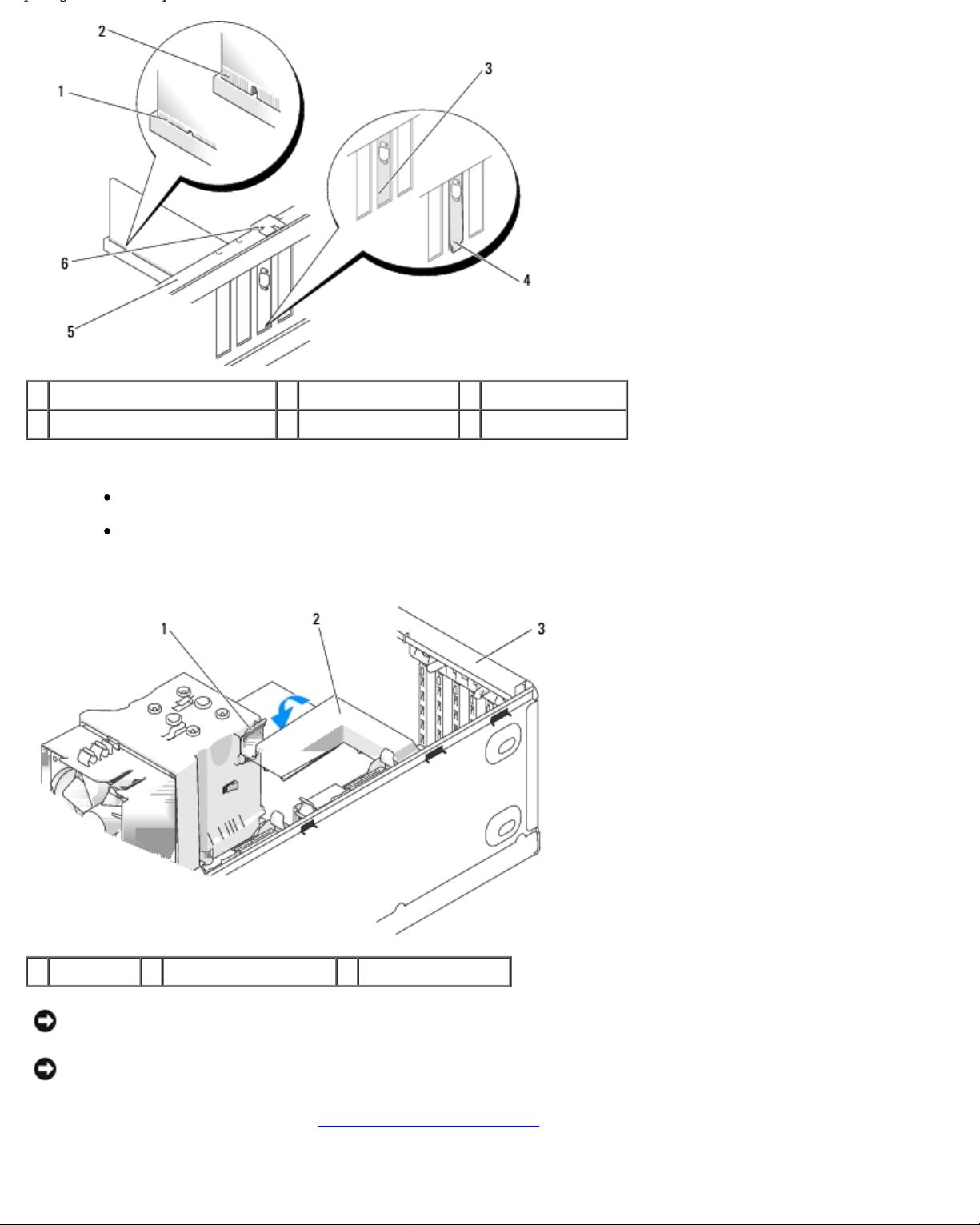
1 fully seated card 2 not fully seated card 3 bracket within slot
4 bracket caught outside of slot 5 alignment bar 6 alignment guide
11. Ensure that:
The tops of all cards and filler brackets are flush with the alignment bar.
The notch in the top of the card or filler bracket fits around the alignment guide.
12. If you removed a card retention bracket, snap it into place, securing the PCI Express card.
1 release tab 2 card retention bracket 3 card retention door
NOTICE: Do not route card cables over or behind the cards. Cables routed over the cards can prevent the computer
cover from closing properly or cause damage to the equipment.
NOTICE: To connect a network cable, first plug the cable into the network device and then plug the cable into the
computer.
13. Replace the computer cover (see Replacing the Computer Cover
14. Connect the computer and devices to electrical outlets, and then turn them on.
).
Page 15
15. To complete the installation, see Configuring Your Computer After Removing or Installing PCI and PCI Express Cards.
Configuring Your Computer After Removing or Installing PCI and
PCI Express Cards
NOTE: For information on location of connectors, see the Quick Reference Guide. For information on installing drivers
and software for your card, see the documentation that shipped with the card.
Installed Removed
Sound
Card
Network
Card
Back to Contents Page
1. Enter system setup (see
System Setup
2. Go to Onboard Devices
and select Integrated
Audio, and then change
the setting to Off.
3. Connect the external audio
devices to the sound
card's connectors.
1. Enter system setup (see
System Setup
2. Go to Onboard Devices
and select Integrated
NIC, and then change the
setting to Off.
3. Connect the network cable
to the network card's
connector.
1. Enter system setup (see
).
).
System Setup
2. Go to Onboard Devices
and select Integrated
Audio, and then change
the setting to On.
3. Connect the external audio
devices to the computer's
back panel connectors.
1. Enter system setup (see
System Setup
2. Go to Onboard Devices
and select Integrated
NIC, and then change the
setting to On.
3. Connect the network cable
to the integrated network
connector.
).
).
Page 16
Back to Contents Page
Replacing Drives
Dell™ XPS™ 430 Service Manual
Replacing a Hard Drive
Replacing the Drive Panel
Replacing an Optical Drive
Replacing a Media Card Reader
CAUTION: Before working inside your computer, read the safety information that shipped with your
computer. For additional safety best practices information, see the Regulatory Compliance Homepage at
www.dell.com/regulatory_compliance.
NOTE: The system does not support IDE devices.
NOTE: The 3.5-inch Media Card Reader is not interchangeable with the hard drive carrier.
Replacing a Hard Drive
NOTICE: If you are replacing a hard drive that contains data you want to keep, back up your files before you begin this
procedure.
1. Follow the procedures in Before You Begin
2. Remove the computer cover (see Removing the Computer Cover).
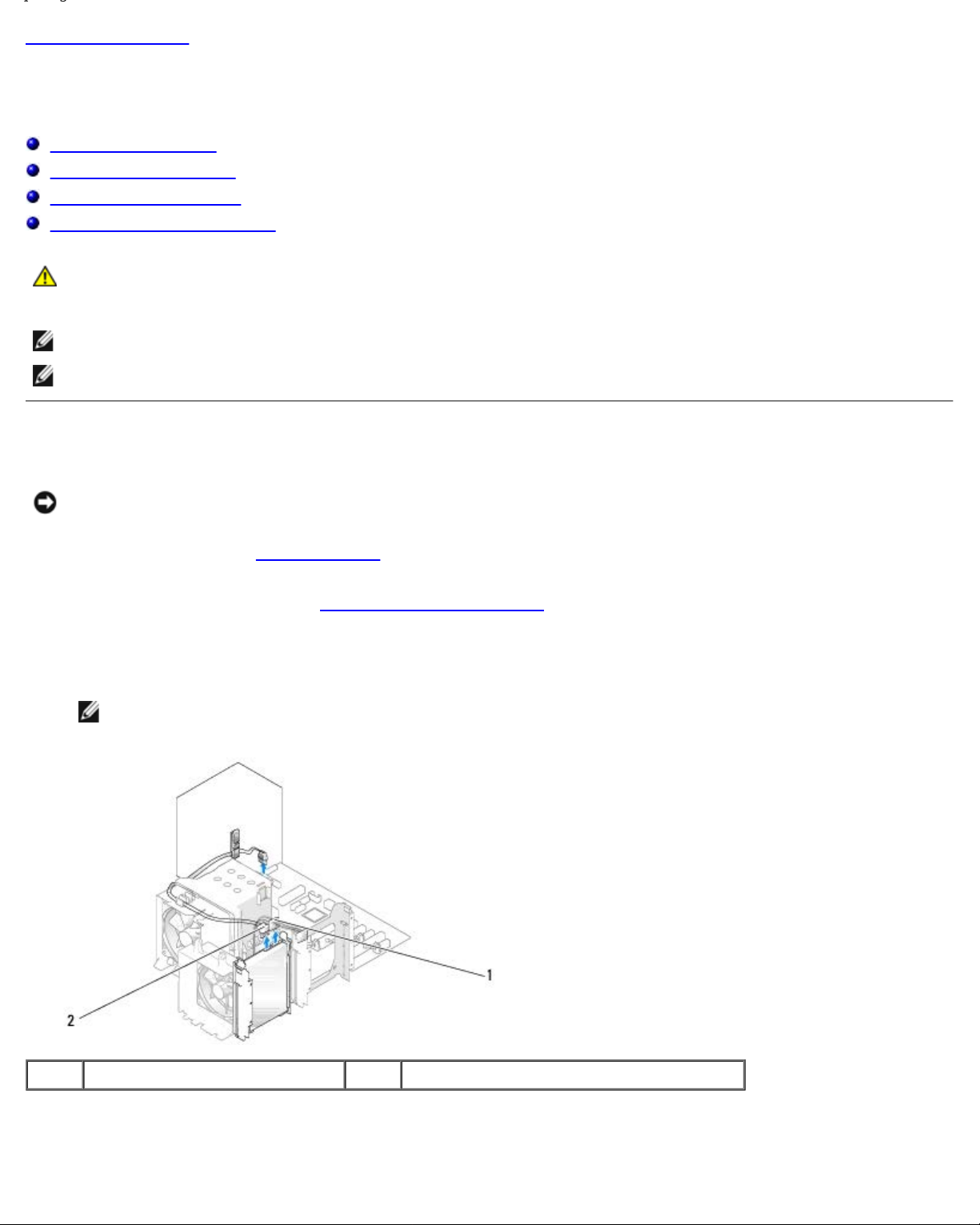
3. Disconnect the power and data cables from the drive.
NOTE: If you are not replacing the hard drive at this time, disconnect the other end of the data cable from the
system board and set it aside. You can use the data cable to install a hard drive at a later time.
.
1 power cable 2 hard drive cable
4. Press in on the tabs on each side of the drive and slide the drive up and out.
Page 17
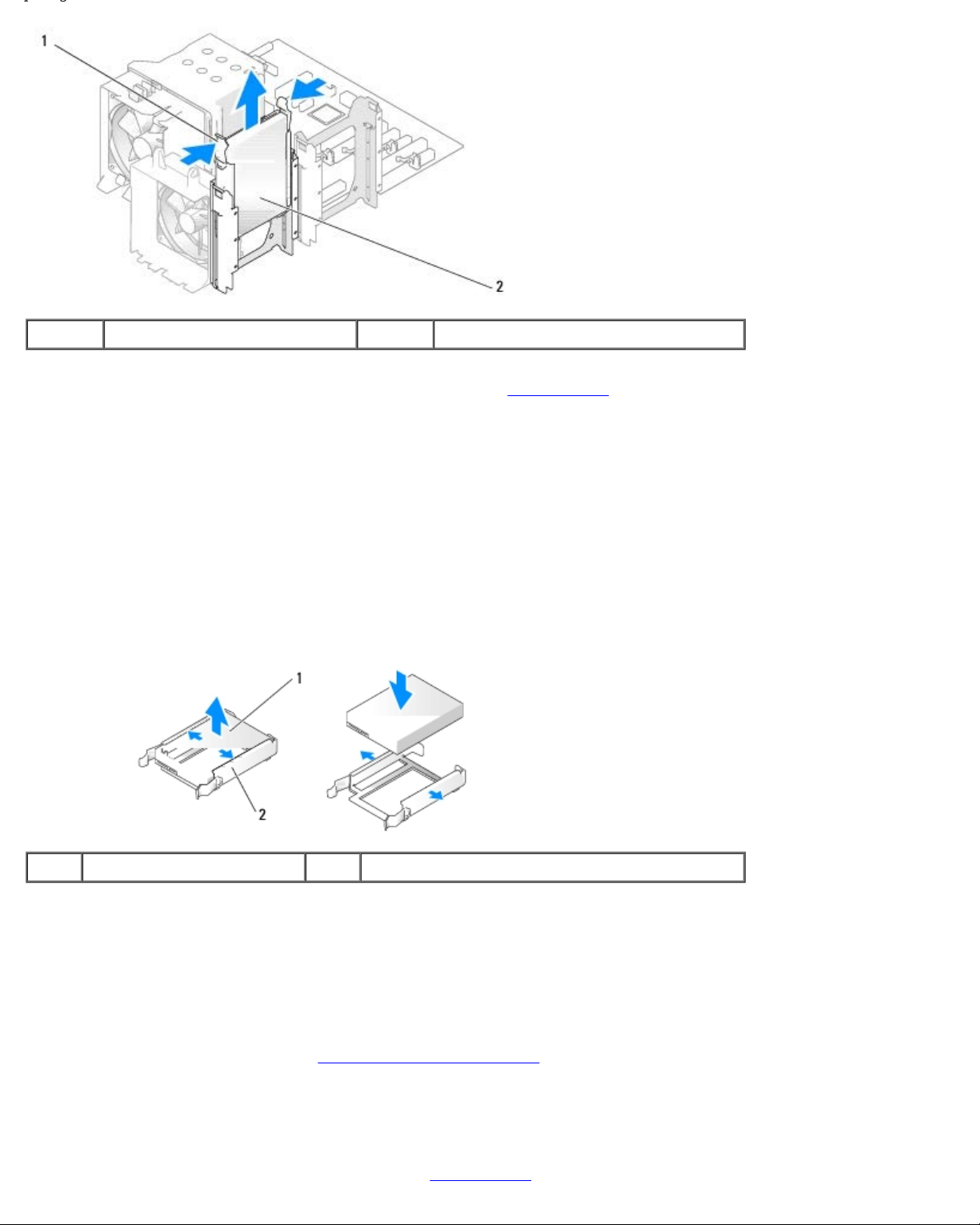
1 tabs (2) 2 hard drive
5. If removing this drive changes the drive configuration, you must ensure that the changes are reflected in the BIOS.
When you restart your computer, enter system setup (see System Setup
section and set the SATA ports (SATA 0 through 4) to the correct configuration.
6. Unpack the replacement hard drive, and prepare it for installation.
7. Check the documentation that came with the drive to verify that the drive is configured for your computer.
8. If your replacement hard drive does not have the hard-drive bracket attached, remove the bracket from the old hard
drive by unsnapping it from the drive.
9. Snap the hard-drive bracket onto the replacement hard drive.
). On the setup screen go to the "Drives"
1 hard drive 2 hard-drive bracket
10. Install the hard drive into the computer by sliding the drive into place until it clicks into place.
11. Connect the power and hard drive cables to the hard drive.
12. Check all connectors to be certain that they are properly cabled and firmly seated.
13. Replace the computer cover (see Replacing the Computer Cover
14. Connect your computer and devices to electrical outlets, and then turn them on.
15. If installing this drive changes the drive configuration, ensure that you reflect these changes in the BIOS. When you
restart your computer, enter system setup (see System Setup
).
). On the setup screen go to the "Drives" section and set
Page 18

the SATA ports (SATA 0 through 4) to the correct configuration.
16. See the documentation that came with the hard drive for instructions about installing any software required for the
operation of the hard drive.
Installing a Hard Drive in the FlexBay
The top FlexBay drive on your system can hold an additional hard drive.
1 hard drive 2 sliding plate lever 3 flexbay knob (default position)
1. Follow the procedures in Before You Begin
2. Remove the computer cover (see Removing the Computer Cover).
3. Remove the drive panel (see Replacing the Drive Panel).
4. Remove the shoulder screws from the inside of the drive-panel insert and attach the screws to the new drive (see
Replacing the Drive-Panel Insert
5. Turn the FlexBay knob on the cage by 90 degrees, in the anti-clockwise direction.
NOTICE: Ensure the FlexBay knob is turned in the anticlockwise direction, failing which can result in the knob being
broken.
NOTE: Turning the FlexBay knob once opens up the drive space to accommodate a larger device like a hard drive.
The knob at this stage is in a horizontal position.
6. Pull the sliding plate lever down and hold in place.
).
.
7. Slide the hard drive into the flex bay drive until the sliding plate clicks into place and the drive snaps into position.
8. Attach the power and hard drive cables to the hard drive.
9. Replace the drive panel (see Replacing the Drive Panel
).
Page 19

10. Replace the computer cover (see Replacing the Computer Cover).
Removing a Hard Drive From the FlexBay
1. Follow the procedures in Before You Begin.
2. Remove the computer cover (see Removing the Computer Cover).
3. Remove the drive panel (see Replacing the Drive Panel).
4. Disconnect the power and hard-drive cables from the back of the drive.
5. Pull the sliding plate down and hold in place.
6. Slide the hard drive out of the FlexBay.
NOTICE: Ensure the FlexBay knob is turned in the anticlockwise direction, failing which can result in the knob being
broken.
7. Turn the FlexBay knob to its default position. See the illustration for Installing a Hard Drive in the FlexBay
default FlexBay knob position.
8. Replace the drive panel (see Replacing the Drive Panel
9. Replace the computer cover (see Replacing the Computer Cover).
).
Replacing the Drive Panel
1. Follow the procedures in Before You Begin.
2. Remove the computer cover (see Removing the Computer Cover).
to note the
Page 20

1 sliding plate lever 2 sliding plate 3 drive panel
3. Grasping the lever on the sliding plate, pull the sliding plate downward and hold in place.
NOTE: The sliding plate secures and releases the drive panel and helps to secure the drives. Push from the inside and
pivot the drive panel to the left to release the panel from its side hinges.
4. The drive panel clicks open. Gently ease it out and set it aside in a secure location.
5. To replace the drive panel:
a. Align the drive panel tabs with the side-door hinges.
b. Rotate the drive panel towards the computer until the sliding plate lever clicks into place and the drive panel
snaps into place on the front panel.
c. Replace the computer cover (see Replacing the Computer Cover.
Replacing the Drive-Panel Insert
Page 21

1 drive panel 2 drive-panel insert tab (2) 3 drive-panel insert
1. Remove the drive panel (see Replacing the Drive Panel
2. Turn the drive panel around to find and hold both outer edges of the
drive- panel insert tab. Pull the drive-panel insert tabs inwards to ease it out of the latches that hold it in place.
3. Set the drive-panel insert aside in a secure location.
4. To replace the drive-panel insert:
a. Align the notches on the drive-panel insert to the corresponding slots on the drive panel and snap into place.
b. Ensure that the drive-panel insert is correctly seated in the drive panel.
).
Replacing an Optical Drive
1. Follow the procedures in Before You Begin.
2. Remove the computer cover (see Removing the Computer Cover).
3. Remove the drive panel (see Replacing the Drive Panel).
4. Disconnect the power cable and the optical drive data cable from the back of the drive.
NOTE: If you are uninstalling the only optical drive in your computer and will not replace it at this time,
disconnect the data cable from the system board and set it aside.
Page 22

1 optical drive cable 2 power cable 3 system board
5. Pull the sliding plate towards the bottom of the system and hold; then, slide the drive out through the front of the
computer.
1 sliding plate 2 optical drive
6. If you are not replacing the drive, replace the drive panel insert (see Replacing the Drive-Panel Insert
step 8
7. If you are installing a new drive:
.
a. Remove the drive panel insert (see Replacing the Drive-Panel Insert
b. Remove three shoulder screws from the inside of the drive-panel insert and attach the screws to the new drive.
).
), and then go to
Page 23

1 optical drive 2 shoulder screws (3)
c. Slide the drive into the drive bay until the drive clicks into position.
d. Connect the power cable and the optical drive data cable to the drive.
e. Check all cable connections, and fold cables out of the way to provide airflow for the fan and cooling vents.
8. Replace the drive panel (see Replacing the Drive Panel
9. Replace the computer cover (see Replacing the Computer Cover).
10. Connect your computer and devices to their electrical outlets, and then turn them on.
11. Verify that your computer works correctly by running the Dell Diagnostics (see "Dell Diagnostics" in the Quick Reference
Guide).
).
Replacing a Media Card Reader
NOTICE: Carefully note the routing of each cable before you disconnect it, so that you are sure to re-route cables
correctly. An incorrectly routed or a disconnected cable could lead to computer problems.
1. Follow the procedures in Before You Begin
2. Remove the computer cover (see Removing the Computer Cover).
3. Remove the drive panel (see Replacing the Drive Panel).
.
Page 24

1 Media Card Reader (not present on all computers) 2 USB cable
4. Disconnect the USB cable from the back of the Media Card Reader. Disconnect the other end of the cable from the USB
connector (FLEXBAY) on the system board (see System Board Components
).
1 sliding plate 2 sliding plate lever 3 Media Card Reader (not present on all computers)
5. Pull the sliding plate towards the bottom of the system and hold; then, slide the drive out through the front of the
computer.
6. If you are not reinstalling the Media Card Reader, replace the drive panel insert (see Replacing the Drive-Panel Insert
and go to step 8
NOTICE: Ensure the FlexBay knob is turned in the anticlockwise direction, failing which can result in the knob being
broken.
NOTE: If you have already installed an additional hard drive in the FlexBay and you want to replace it with a Media Card
Reader, ensure that the FlexBay knob is rotated anticlockwise, back to its default vertical position. See the illustration
for Installing a Hard Drive in the FlexBay
7. If you are installing a new Media Card Reader:
.
.
)
Page 25

a. Remove the drive panel insert (see Replacing the Drive-Panel Insert).
b. Remove the Media Card Reader from its packaging.
c. Remove the shoulder screws from the inside of the drive-panel insert and attach the screws to the new Media
Card Reader.
1 Media Card Reader 2 screws (4)
d. Gently slide the Media Card Reader into the drive bay, till it clicks in securely.
NOTE: Ensure that the Media Card Reader is installed before connecting the USB cable.
e. Connect the USB cable to the back of the Media Card Reader and to the USB connector (FLEXBAY) on the system
board (see System
Board Components).
8. Replace the drive panel (see Replacing the Drive Panel
9. Replace the computer cover (see Replacing the Computer Cover).
10. Turn on the system and enter system setup (see System Setup).
If you removed a Media Card Reader — Set the USB for FlexBay value to OFF.
If you installed a Media Card Reader — Set the USB for FlexBay value to ON.
Back to Contents Page
).
Page 26

Back to Contents Page
Replacing Fans
Dell™ XPS™ 430 Service Manual
Replacing the Processor Airflow Shroud Assembly
Replacing the Processor Fan Cage
Replacing the Processor Fan
Replacing the Card Fan
CAUTION: Before working inside your computer, read the safety information that shipped with your
computer. For additional safety best practices information, see the Regulatory Compliance Homepage at
www.dell.com/regulatory_compliance.
CAUTION: To guard against likelihood of electric shock, laceration by moving fan blades or other
unexpected injuries, always unplug your computer from the electrical outlet before removing the cover.
Replacing the Processor Airflow Shroud Assembly
1. Follow the procedures in Before You Begin.
2. Remove the computer cover (see Removing the Computer Cover).
CAUTION: The processor heat sink can get very hot during normal operation. Be sure that the heat sink has
had sufficient time to cool before you touch it.
1 processor airflow shroud 2 captive screws (2)
NOTICE: The processor heat sink is attached to the processor airflow shroud. When you remove the airflow shroud, lay
it upside down or on its side to avoid damaging the heat sink thermal interface.
3. Loosen the two captive screws securing the processor airflow shroud to the chassis, then pivot the shroud forward and
ease it out of the hinges.
Page 27

4. If present on your computer, remove the card retention bracket (see Removing PCI and PCI Express Cards).
5. Lift the processor airflow shroud out of the computer, and set it aside.
6. To replace the processor airflow shroud, align the hinge slots on the processor airflow shroud with the hinge guides on
the system board.
7. Align the other side of the processor airflow shroud towards the processor fan, and then tighten the two captive screws.
8. If you removed a card retention bracket, snap it back into place (see Installing PCI and PCI Express Cards
9. Replace the computer cover (see Replacing the Computer Cover).
10. Connect your computer and devices to electrical outlets, and turn them on.
).
Replacing the Processor Fan Cage
1. Follow the procedures in Before You Begin.
2. Remove the computer cover (see Removing the Computer Cover).
3. Remove the processor airflow shroud (see Replacing the Processor Airflow Shroud Assembly).
4. Disconnect the processor fan cable from the FAN_CPU connector on the system board (see System Board Components).
5. Lift and hold the release tab present at the bottom of the processor fan cage, press down on top of the cage and slide it
towards the back of the computer.
6. Ease the cage out of the housing.
7. To replace the processor fan cage, orient the processor fan power cable downward; insert the tabs along the bottom of
the processor fan cage into the corresponding slots on the cage housing and slide the processor fan cage towards the
front of the computer, until it snaps into place.
Page 28

8. Connect the processor fan cable to the FAN_CPU connector on the system board (see System Board Components).
9. Replace the processor airflow shroud (see Replacing the Processor Airflow Shroud Assembly).
10. Replace the computer cover (see Replacing the Computer Cover).
Replacing the Processor Fan
1. Follow the procedures in Before You Begin.
2. Remove the computer cover (see Removing the Computer Cover).
3. Remove the processor airflow shroud (see Replacing the Processor Airflow Shroud Assembly).
4. Disconnect the processor fan cable from the FAN_CPU connector on the system board (see System Board Components).
5. Remove the processor fan cage from the cage housing (see Replacing the Processor Fan Cage).
6. Release the two tabs at the top and the bottom of the processor fan cage.
7. Carefully pull on the two bottom corners of the fan to detach the four rubber grommets securing the fan to the
processor fan cage.
1 fan cage 2 rubber grommet (4)
3 processor fan 4 release tabs (2)
8. To replace the processor fan, orient the fan power cable downward. Align the rubber grommets in the fan with the holes
in each corner of the processor airflow shroud, then pull the grommets through until they snap into place.
NOTE: Airflow direction and orientation are shown on the side of the fan.
9. Replace the processor fan cage into the cage housing (see Replacing the
Processor Fan Cage).
Page 29

10. Connect the fan cable to the FAN_CPU connector on the system board (see System Board Components).
11. Replace the processor airflow shroud (see Replacing the Processor Airflow Shroud Assembly).
12. Replace the computer cover (see Replacing the Computer Cover).
13. Connect your computer and devices to electrical outlets, and then turn them on.
Replacing the Card Fan
1. Follow the procedures in Before You Begin.
2. Remove the computer cover (see Removing the Computer Cover).
3. Remove any full-length expansion cards (see Replacing PCI and PCI Express Cards).
4. Disconnect the fan cable from the FAN_CARD_CAGE connector on the system board (see System Board Components).
5. Lift and hold the tab present at the bottom of the fan cage. Pressing the top of the cage, slide it towards the back of the
computer. Gently ease the cage out of the groove.
1 fan cage 2 tab
6. One by one, carefully pull on each corner of the fan to detach the four rubber grommets securing the fan to the fan
cage.
Page 30

1 card fan 2 rubber grommet (4) 3 card fan cage
NOTICE: Ensure the fan cable is correctly routed through the opening in the lower-right corner of the fan cage.
7. To reinstall the card fan, orient the fan power cable downward. Align the rubber grommets in the fan with the holes in
each corner of the fan cage, then pull the grommets through until they snap into place.
NOTE: Airflow direction and orientation are shown on the side of the fan. Insert the tabs along the bottom of the
fan cage into the corresponding slots on the cage housing, then rotate the fan cage forward until it snaps into
place.
8. Connect the fan cable to the FAN_CARD_CAGE connector on the system board (see System Board Components
9. Replace any expansion cards that you removed (see Installing PCI and PCI Express Cards).
10. Replace the computer cover (see Replacing the Computer Cover).
11. Connect your computer and devices to electrical outlets, and then turn them on.
Back to Contents Page
).
Page 31

Back to Contents Page
Replacing the Front I/O Panel
Dell™ XPS™ 430 Service Manual
Front I/O-Panel Components
CAUTION: Before working inside your computer, read the safety information that shipped with your
computer. For additional safety best practices information, see the Regulatory Compliance Homepage at
www.dell.com/regulatory_compliance.
Front I/O-Panel Components
1 add-in audio internal connector 2 1394a internal connector 3 power button connector
4 front I/O connector 5 microphone-in connector 6 headphone-out connector
7 USB 2.0 connectors (2) 8 1394a external connector
To replace the front I/O panel:
1. Follow the procedures in Before You Begin
2. Remove the computer cover (see Removing the Computer Cover).
NOTICE: Carefully note the routing of each cable before you disconnect it, so that you are sure to re-route cables
correctly. An incorrectly routed or a disconnected cable could lead to computer problems.
3. Remove the front plastic bezel:
a. Remove the drive panel (see Replacing the Drive Panel
b. Remove the two screws from the bottom of the chassis.
c. Press out to release the six tabs that secure the bezel to the front panel.
d. Pull the bezel away from the front of the computer.
.
).
Page 32

1 Bezel tabs (6) 2 Bezel screws (2)
4. Remove the processor airflow shroud (see Replacing the Processor Airflow
5. Remove the processor fan assembly (seeReplacing the Processor Fan Cage and Replacing the Processor Fan) and the
card fan (seeReplacing the Card
6. Disconnect the control-panel cable from the I/O panel connector by pulling the cable loop.
7. Disconnect the power panel cable, 1394 cable, and audio cable (if it exists) so that the entire front I/O panel is free from
all cables.
Fan).
Shroud Assembly).
1 Front I/O panel 2 mounting screws (2)
8. Remove the two screws that hold the I/O panel assembly to the front of the chassis.
9. Gently ease out the lower end of the I/O panel assembly first from its groove on the chassis followed by the upper end.
Page 33

10. To replace the front I/O panel, align the screw holes on the I/O panel with the screw holes on the chassis, and replace
the two screws.
11. Reconnect the cable that attaches the power button to the I/O panel.
12. Reconnect the 1394 cable, and audio cable (if it exists and you had removed it).
13. Reconnect the control-panel cable to the I/O panel connector.
14. Replace the front bezel:
a. Align the six tabs with the corresponding slots on the front panel and snap it back into place.
b. Replace the two screws that secure the bezel to the bottom of the chassis.
c. Replace the drive panel (see Replacing the Drive Panel
15. Replace the processor airflow shroud (see Replacing the Processor Airflow
assembly (see Replacing the
16. Connect the card fan assembly (see Replacing the Card Fan)to the system board.
17. Replace the computer cover (see Replacing the Computer Cover).
Back to Contents Page
Processor Fan Cage and Replacing the Processor Fan).
).
Shroud Assembly) and the processor fan
Page 34

Back to Contents Page
Replacing the Processor
Dell™ XPS™ 430 Service Manual
Removing the Processor
Installing the Processor
CAUTION: Before working inside your computer, read the safety information that shipped with your
computer. For additional safety best practices information, see the Regulatory Compliance Homepage at
www.dell.com/regulatory_compliance.
NOTICE: Do not perform the following steps unless you are familiar with hardware removal and replacement.
Performing these steps incorrectly could damage your system board. For technical service, see the Quick Reference
Guide.
Removing the Processor
1. Follow the procedures in Before You Begin.
2. Remove the computer cover (see Removing the Computer Cover).
3. Disconnect the power cables from the POWER and 12VPOWER connectors (see System Board Components) on the
system board.
4. Remove the airflow shroud (see Replacing the Processor Airflow Shroud
5. Push down and out on the socket release lever.
6. Lift the socket release lever and open the processor cover.
Assembly).
1 processor cover 2 processor
3 socket 4 socket release lever
7. Remove the processor from the socket.
Leave the release lever extended in the release position so that the socket is ready for the new processor.
Page 35

Installing the Processor
NOTICE: Ground yourself by touching an unpainted metal surface on the back of the computer.
1. Unpack the new processor.
NOTICE: You must position the processor correctly in the socket to avoid permanent damage to the processor and the
computer when you turn on the computer.
2. If the release lever on the socket is not fully extended, move it to that position.
3. Align the pin-1 corner of the processor and socket.
1 processor cover 2 processor 3 socket
4 socket release lever 5 socket pin-1 indicator
NOTICE: Socket pins are delicate. To avoid damage, ensure that the processor is aligned properly with the socket, and
do not use excessive force when you install the processor. Be careful not to touch or bend the pins on the system
board.
4. Set the processor lightly in the socket and ensure that the processor is positioned correctly.
5. When the processor is fully seated in the socket, close the processor cover.
6. Pivot the socket release lever back toward the socket and snap it into place to secure the processor.
7. Replace the processor airflow shroud (see Replacing the Processor Airflow
8. Reconnect the power cables to the POWER and 12VPOWER connectors (see System Board Components) on the system
board.
9. Close the computer cover (see Replacing the Computer Cover
).
Shroud Assembly).
10. Connect your computer and devices to electrical outlets, and turn them on.
Page 36

Back to Contents Page
Page 37

Back to Contents Page
Replacing the System Board
Dell™ XPS™ 430 Service Manual
CAUTION: Before working inside your computer, read the safety information that shipped with your
computer. For additional safety best practices information, see the Regulatory Compliance Homepage at
www.dell.com/regulatory_compliance.
NOTICE: Do not perform the following steps unless you are familiar with hardware removal and replacement.
Performing these steps incorrectly could damage your system board. For technical service, see the Quick Reference
Guide.
NOTICE: The system board and metal tray are connected and are removed or installed as one piece.
1. Follow the procedures in Before You Begin
2. Remove the computer cover (see Removing the Computer Cover).
3. Remove any full-length expansion cards (see Replacing PCI and PCI Express Cards).
4. Remove the processor airflow shroud (see Replacing the Processor Airflow Shroud Assembly) and the processor fan
assembly (see Replacing the
5. Remove the card fan assembly (see Replacing the Card Fan).
6. Remove any additional components that may restrict access to the system board.
7. Disconnect all cables from the system board.
NOTICE: If you are replacing the system board, visually compare the replacement system board to the existing system
board to ensure that you have the correct part.
8. Remove the eight screws securing the system board assembly to the chassis, slide the system board assembly towards
the front of the computer and lift it up and out.
Processor Fan Cage and Replacing the Processor Fan).
.
NOTE: Some components and connectors on replacement system boards may be in different locations than
corresponding connectors on the existing system board.
Page 38

NOTE: Jumper settings on replacement system boards are preset at the factory.
9. Transfer components from the existing system board to the replacement system board, if applicable.
10. Orient the system board assembly by aligning the notches on the bottom of the assembly with the tabs on the
computer.
11. Slide the system board assembly toward the back of the computer until the assembly clicks into place.
12. Replace the eight screws to secure the system board assembly to the chassis.
13. Replace any expansion cards that you removed (see Installing PCI and PCI
14. Replace the processor airflow shroud (see Replacing the Processor Airflow Shroud Assembly) and the Processor Fan
assembly (see Replacing the
15. Replace the card fan assembly (see Replacing the Card Fan).
16. Replace any additional components that you removed from the system board.
17. Reconnect all cables to the system board.
18. Replace the computer cover (see Replacing the Computer Cover).
19. Connect your computer and devices to electrical outlets, and then turn them on.
20. Flash the system BIOS, as needed.
NOTE: For information on flashing the system BIOS, see support.dell.com.
Processor Fan Cage and Replacing the Processor Fan).
Express Cards).
Back to Contents Page
Page 39

Back to Contents Page
Replacing the Power Supply
Dell™ XPS™ 430 Service Manual
CAUTION: Before working inside your computer, read the safety information that shipped with your
computer. For additional safety best practices information, see the Regulatory Compliance Homepage at
www.dell.com/regulatory_compliance.
CAUTION: To guard against likelihood of electric shock, laceration by moving fan blades or other
unexpected injuries, always unplug your computer from the electrical outlet before removing the cover.
1. Follow the procedures in Before You Begin
2. Remove the computer cover (see Removing the Computer Cover).
NOTICE: Note the location and ID of each power connector before disconnecting the power supply cables.
3. Follow the DC power cables that stem from the power supply and disconnect each connected power cable.
NOTE: Note the routing of the power cable bundles as you disconnect them. You must route these cables properly
when you replace them to prevent them from being pinched or crimped.
4. Remove the four screws that attach the power supply assembly to the back of the chassis.
5. Press and hold the metal release tab at the bottom of the power supply unit, push the power supply towards the front of
the computer to free it from the securing tabs on the computer chassis.
6. Gather the power supply bundles that stem from the power supply, for easy removal and lift it out of the computer.
.
1 power supply screws (4)
Page 40

7. To replace the power supply, align the bottom of the power supply unit with the tabs on the chassis, then slide it
towards the back of the system till it snaps into place.
8. Replace the four screws that secure the power supply to the back of the chassis.
9. Reattach each of the DC power cables that were previously connected, carefully rerouting them as you found them.
10. Replace the computer cover (see Replacing the Computer Cover).
11. Connect your computer and devices to electrical outlets, and then turn them on.
Back to Contents Page
Page 41

Back to Contents Page
Replacing the Battery
Dell™ XPS™ 430 Service Manual
CAUTION: Before working inside your computer, read the safety information that shipped with your
computer. For additional safety best practices information, see the Regulatory Compliance Homepage at
www.dell.com/regulatory_compliance.
CAUTION: A new battery can explode if it is incorrectly installed. Replace the battery only with the same or
equivalent type recommended by the manufacturer. Discard used batteries according to the
manufacturer's instructions.
To replace the battery:
1. Enter the system setup program and record the values for all the screens (see Entering System Setup
restore the correct settings after installing the new battery.
2. Follow the procedures in Before You Begin
3. Remove the computer cover (see Removing the Computer Cover).
4. Locate the battery socket (see System Board Components).
NOTICE: If you pry the battery out of its socket with a blunt object, be careful not to touch the system board with the
object. Ensure that the object is inserted between the battery and the socket before you attempt to pry out the
battery. Otherwise, you may damage the system board by prying off the socket or by breaking circuit traces on the
system board.
5. Remove the battery by carefully prying it out of its socket with your fingers or with a blunt, nonconducting object, such
as a plastic screwdriver.
6. Insert the new battery into the socket with the side labeled "+" facing up, and then snap the battery into place.
7. Replace the computer cover. (see Replacing the Computer Cover
.
).
) so that you can
1 coin-cell battery 2 tab 3 battery socket
8. Connect your computer and devices to electrical outlets, and then turn them on.
Page 42

9. Enter system setup and restore the settings you recorded in step 1 (see Entering System Setup).
10. Properly dispose of the old battery. See the safety instructions that shipped with your computer for battery disposal
information.
Back to Contents Page
Page 43

Back to Contents Page
Replacing the Computer Cover
Dell™ XPS™ 430 Service Manual
CAUTION: Before working inside your computer, read the safety information that shipped with your
computer. For additional safety best practices information, see the Regulatory Compliance Homepage at
www.dell.com/regulatory_compliance.
CAUTION: Do not operate your equipment with any cover(s) (including computer covers, front panel, filler
brackets, front-panel inserts, etc.) removed.
1. Ensure that all cables are connected, and fold cables out of the way.
Gently pull the power cables toward you so that they do not get caught underneath the drives.
2. Ensure that no tools or extra parts are left inside the computer.
3. Lower the cover into place:
a. Pivot the cover down.
b. Press down on the right side of the cover until it closes.
c. Press down on the left side of the cover until it closes.
4. Ensure that both sides of the cover are locked. If not, repeat all of step 3.
5. Connect your computer and devices to electrical outlets, and then turn them on.
Back to Contents Page
Page 44

Back to Contents Page
System Setup
Dell™ XPS™ 430 Service Manual
Overview
Entering System Setup
Boot Sequence
Clearing Forgotten Passwords
Clearing CMOS Settings
Overview
Use system setup as follows:
To change the system configuration information after you add, change, or remove any hardware in your computer
To set or change a user-selectable option such as the user password
To read the current amount of memory or set the type of hard drive installed
Before you use system setup, it is recommended that you write down the system setup screen information for future
reference.
NOTICE: Do not change the settings in system setup unless you are an expert computer user. Certain changes can
cause your computer to work incorrectly.
Entering System Setup
1. Turn on (or restart) your computer.
2. When the DELL logo appears, press <F2> immediately.
NOTE: Keyboard failure may result when a key on the keyboard is held down for extended periods of time. To
avoid possible keyboard failure, press and release <F2> in even intervals until the system setup screen appears.
If you wait too long and the operating system logo appears, continue to wait until you see the Microsoft® Windows®
desktop, then shut down your computer and try again.
System Setup Screens
The system setup screen displays current or changeable configuration information for your computer. Information on the
screen is divided into three areas: the options list, the active options field, and key functions.
Options List — This field appears on the left side of the
system setup window. The field is a scrollable list
containing features that define the configuration of your
computer, including installed hardware, power
conservation, and security features.
Scroll up and down the list with the up- and down-arrow
keys. As an option is highlighted, the Options Field
Options Field — This field appears on the right side of the
system setup window and contains information about each
option listed in the Options List. In this field you can view
information about your computer and make changes to your
current settings.
Press the left- and right-arrow keys to highlight an option.
Press <Enter> to make that selection active and return to the
Page 45

displays more information about that option and the
option's current and available settings.
Options List.
NOTE: Not all settings listed in the Options Field are
changeable.
Key Functions — This field appears below the Options Field
and lists keys and their functions within the active system
setup field.
System Setup Options
NOTE: Depending on your computer and installed devices, the items listed in this section may not appear, or may not
appear exactly as listed.
System
System Info Lists system information such as the
system model number, the BIOS version
number and date, the system service tag,
express service code and asset tag, and
other system-specific information.
Processor Info Identifies the processor type, clock speed,
bus speed, L2 cache, L3 cache, ID, and
whether the processor is multiple core
capable, supports Hyper-Threading and
supports 64-bit technology.
Memory Info Identifies the memory type, speed, and
channel mode (dual or single) by DIMM
slot location.
PCI Info Indicates the expansion card type by slot
location.
Date/Time Displays current date and time settings.
Boot Sequence The computer attempts to boot from the
sequence of devices specified in this list.
NOTE: If you insert a boot device and
restart the computer, this option appears
in the system setup menu. To boot from
a USB memory device, for example,
select the USB device and move it so that
it becomes the first device in the boot
sequence.
Drives
SATA Drives 0 through 4
(On default)
Enables or disables drives attached to the
SATA connectors on the system board.
Off — A device attached to the
interface is not usable.
On — A device attached to the
interface is usable.
Page 46

eSATA
Enables or disables eSATA.
(On default)
Off — eSATA is disabled.
On — eSATA is enabled.
NOTE: eSATA is not supported in ATA
mode.
SATA Operation
(RAID On default)
Onboard Devices
Integrated NIC
(On default)
Enables or disables RAID (for more
information, see the Dell Technology
Guide).
RAID Autodetect/ATA — RAID if
signed drives, otherwise ATA.
RAID On — SATA is configured for
RAID on every boot.
Enables or disables the integrated network
interface controller (NIC).
Off — The integrated NIC is
disabled.
On — The integrated NIC is
enabled.
On w/PXE — The integrated NIC is
on (with PXE enabled).
NOTE: PXE is required only if you are
booting to an operating system located
on another computer. If a boot routine is
not available from the remote system,
the computer attempts to boot from the
next device listed in the boot sequence.
Integrated Audio
(Auto default)
USB Controller
(On default)
Rear Tri USB
(On default)
Enables or disables the onboard audio
controller.
Off — Integrated audio is disabled.
On — Integrated audio is enabled.
Auto — If installed, the add-in
audio controller is enabled.
Enables or disables the internal USB
controller. Set to On (default) so that
USB devices will be detected and
supported in the operating system.
Off — The USB controller is
disabled.
On — The USB controller is
enabled.
No Boot — The USB controller is
enabled; however, the BIOS will
not recognize USB storage devices.
NOTE: Operating systems with USB
support will recognize USB storage
devices regardless of the No Boot
setting.
Enables or disables the indicated group of
USB ports.
Off — The USB group is disabled.
Page 47

On — The USB group is enabled.
Rear Dual USB
(On default)
Enables or disables the indicated group of
USB ports.
Off — The USB group is disabled.
On — The USB group is enabled.
Front USB
(On default)
USB for FlexBay
(No Boot default)
1394 Controller
(On default)
Media Accelerator
(On default)
Enables or disables the indicated group of
USB ports.
Off — The USB group is disabled.
On — The USB group is enabled.
Enables or disables the internal USB for
FlexBay.
Off — Internal USB for FlexBay is
disabled.
On — Internal USB for FlexBay is
enabled.
No Boot — Internal USB for
FlexBay is enabled, but not
bootable.
Enables or disables the integrated IEEE
1394 controller.
Off — The 1394 controller is
disabled.
On — The 1394 controller is
enabled.
Enables or disables the Media Accelerator
device.
Off — Media Accelerator is
disabled.
On — Media Accelerator is enabled.
Video
Primary Video
(PEG default)
Performance
Multiple CPU Core
(On default)
Specifies the display device the computer
uses first when it starts.
PCI — Use the PCI video controller.
PEG — Use the PCI Express
Graphics video controller.
Specifies whether the processor has more
than one core enabled.
Off — Multiple CPU core technology
is disabled.
On — Multiple CPU core technology
is enabled.
NOTE: The performance of some
applications may improve with an
additional core enabled.
Page 48

SpeedStep
Specifies whether Enhanced Intel
Protection technology is enabled.
(Off default)
SpeedStep® technology is enabled for all
supported processors in the system.
Off — Disable Enhanced SpeedStep
technology
On — Enable Enhanced SpeedStep
technology
Virtualization
(Off default)
HDD Acoustic Mode
(Bypass default)
Specifies whether a virtual machine
monitor (VMM) can utilize the additional
hardware capabilities provided by Intel
®
Virtualization Technology.
Off — Disable Virtualization
Technology
On — Enable Virtualization
Technology
Determines the acoustic mode at which
the hard drive operates.
Bypass — Do nothing (needed for
older drives).
Quiet — The hard drive operates at
a slower, but quieter speed.
Suggested — Allow the hard drive
manufacturer to select the mode.
Performance — The hard drive
operates at a faster, but possibly
noisier speed.
NOTE: Switching to performance mode
may cause an increase in noise produced
by the drive, but does not affect the
drive's performance.
Security
Admin Password
(Not Set default)
System Password
(Not Set default)
Password Changes
(Unlocked default)
Execute Disable
(On default)
NOTE: Changing the acoustics setting
does not alter your hard drive image.
Used to prohibit an unauthorized user
from changing any configuration settings
in the system setup.
Used to prohibit an unauthorized user
from booting to the operating system.
This option locks the system password
field with the administrator (admin)
password.
NOTE: When the system password field is
locked, you can no longer disable
password security by pressing <Ctrl>
<Enter> when the computer starts.
Enables or disables Execute Disable
Memory Protection technology.
Off — Execute Disable Memory
Protection technology is disabled.
On — Execute Disable Memory
Page 49

Power Management
AC Recovery
(Off default)
Auto Power On
(Off default)
Specifies how the computer will behave
when AC power is restored after an AC
power loss.
Off — The system stays off after
AC power is restored.
On — The system powers on after
AC power is restored.
Last — The system returns to the
previous state after AC power is
restored.
Disables or selects when to automatically
turn on the computer.
Off — Do not use the Auto Power
Time.
Everyday — Turn the computer on
every day at the time set in Auto
Power Time.
Weekdays — Turn the computer
on Monday through Friday at the
time set in Auto Power Time.
NOTE: This feature does not work if you
turn off your computer using a power
strip or surge protector.
Auto Power Time Specifies the time to automatically turn on
the computer.
Change the time to automatically turn on
the computer by pressing the up- or
down-arrow key to increase or decrease
the numbers, or type the numbers in the
appropriate time field.
NOTE: This feature does not work if you
turn off your computer using a power
strip or surge protector.
Remote Wake Up
(Off default)
Suspend Mode
(S3 default)
This option allows the computer to power
up when a Network Interface Controller
or Remote Wakeup-capable modem
receives a wake up signal.
Off — Remote wake up is disabled.
On — Remote wake up is enabled.
On w/Boot to NIC — The
computer attempts to boot from a
network prior to using the boot
sequence.
Specifies the power management suspend
mode.
S1 — The computer resumes more
quickly from sleep mode.
S3 — The computer conserves
more power when not in use
(system memory remains active).
Page 50

Maintenance
Service Tag Displays the system service tag.
SERR Message
(On default)
Load Defaults This setting restores the computer's
Event Log Displays the system event log.
Controls the SERR message mechanism.
Some graphics cards require that the
SERR Message mechanism be disabled.
Off — Do not use the SERR
message mechanism.
On — Use the SERR message
mechanism.
factory-installed default settings.
Cancel — Do not restore factoryinstalled default settings.
Continue — Restore factoryinstalled default settings.
Mark all entries — Mark all event
log entries as read (R).
Clear log — Clear all event log
entries.
NOTE: Once an event log entry is marked
as read (R) that entry cannot be marked
as unread (U).
POST Behavior
Fastboot
(On default)
Numlock Key
(On default)
POST Hotkeys
(Setup & Boot Menu default)
Enables or disables the option to speed up
the boot process by skipping certain
configurations and tests.
Off — Do not skip any steps in the
boot process.
On — Boot quickly.
Enables or disables the numerical and
mathematical features of the rightmost
bank of keys on the keyboard.
Off — Right keypad keys function
as arrows.
On — Right keypad keys function
as numbers.
Specifies the function keys to display on
the screen when the computer starts.
Setup & Boot Menu — Display
both messages (F2=Setup and
F12=Boot Menu).
Setup — Display the setup
message only (F2=Setup).
Boot Menu — Display the
Quickboot message only
(F12=Boot Menu).
None — Neither message is
displayed.
Page 51

Keyboard Errors
(Report default)
Enables or disables keyboard error
reporting when the computer starts.
Report — Display any keyboard
errors.
Do not report — Do not display
any keyboard errors.
Boot Sequence
This feature allows you to set the order in which the BIOS will search devices when trying to find an operating system.
NOTICE: If you modify any boot sequence settings, save the new settings to avoid losing the changes.
Option Settings
NOTE: The computer attempts to boot from all bootable devices, but if no bootable device is found, the computer
generates an error message that states No boot device available. Press the <F1> key to retry the boot, or press the
<F2> key to enter the setup utility.
USB Floppy Drive — The computer attempts to boot from the floppy drive. If there is no floppy drive connected to a
USB port, the computer attempts to boot from the next bootable device in the sequence.
NOTE: If there is a non-bootable floppy in the drive, the computer generates an error message. Follow the
instructions on the screen to retry the boot.
Onboard SATA Hard Drive — The computer attempts to boot from the primary hard drive. If no operating system is
on the drive, the computer attempts to boot from the next bootable device.
Onboard or USB CD-ROM Drive — The computer attempts to boot from the CD drive. If no CD is in the drive, or if the
CD has no operating system, the computer attempts to boot from the next bootable device.
USB Device — Insert the memory device into a USB port and restart the computer. When F12 = Boot Menu appears in
the upper-right corner of the screen, press <F12>. The BIOS detects the device and adds the USB option to the boot
menu.
NOTE: To boot to a USB device, the device must be bootable. To ensure that your device is bootable, check the
device documentation.
Changing Boot Sequence for the Current Boot
You can use this feature, for example, to restart your computer to a USB device such as a floppy drive, memory key, or CDRW drive.
NOTE: If you are booting to a USB floppy drive, you must first set the floppy drive to OFF in system setup (see System
Setup Options).
1. If you are booting to a USB device, connect the USB device to a USB connector (see "Front View of the Computer" in the
Quick Reference Guide).
2. Turn on (or restart) your computer.
3. When F2 = Setup, F12 = Boot Menu appears in the upper-right corner of the screen, press <F12>.
Page 52

If you wait too long and the operating system logo appears, continue to wait until you see the Microsoft Windows
desktop, then shut down your computer (see Before You Begin
The Boot Device Menu appears, listing all available boot devices. Each device has a number next to it.
4. At the bottom of the menu, enter the number of the device that is to be used for the current boot only.
For example, if you are booting to a USB memory key, highlight USB Device and press <Enter>.
NOTE: To boot to a USB device, the device must be bootable. To make sure your device is bootable, check the
device documentation.
) and try again.
Changing Boot Sequence for Future Boots
1. Enter system setup (see Entering System Setup).
2. Use the arrow keys to highlight the Boot Sequence menu option and press <Enter> to access the menu.
NOTE: Write down your current boot sequence in case you want to restore it.
3. Press the up- and down-arrow keys to move through the list of devices.
4. Press the spacebar to enable or disable a device (enabled devices have a checkmark).
5. Press plus (+) or minus (–) to move a selected device up or down the list.
Clearing Forgotten Passwords
CAUTION: Before you begin any of the procedures in this section, follow the safety instructions that
shipped with your computer.
NOTICE: This process erases both the system and setup passwords.
1. Follow the procedures in Before You Begin
2. Remove the computer cover (see Removing the Computer Cover).
.
Page 53

3. Locate the RTCRST_PSWD jumper on the system board (see System Board Components), then remove the jumper plug
(located on pins three and four) and set the plug aside.
4. Close the computer cover.
5. Connect your keyboard and mouse, then connect your computer and monitor to electrical outlets and turn them on.
6. After the Microsoft® Windows® desktop appears on your computer, turn the computer off:
a. Save and close all open files and exit all open programs.
b. Shut down the operating system.
NOTE: Ensure that the computer is off and not in a power management mode. If you cannot shut down the
computer using the operating system, press and hold the power button for 4 seconds.
7. Disconnect the keyboard and mouse, then disconnect the computer and monitor from their electrical outlets.
8. Press the power button on the computer to ground the system board.
9. Open the computer cover (see Removing the Computer Cover
10. Locate pins three and four of the RTCRST_PSWD jumper on the system board (see System Board Components), and
then reinstall the jumper plug to enable the password feature.
11. Replace the computer cover (see Replacing the Computer Cover
12. Connect your computer and devices to electrical outlets, and then turn them on.
NOTE: In system setup (see Entering System Setup), both system and administrator password options appear as Not
Set. The password feature is enabled but a password is not assigned.
).
).
Clearing CMOS Settings
CAUTION: Before you begin any of the procedures in this section, follow the safety instructions that
Page 54

shipped with your computer.
NOTE: This procedure clears and resets system and setup passwords.
1. Follow the procedures in Before You Begin
2. Remove the computer cover (see Removing the Computer Cover).
3. Locate the RTCRST_PSWD jumper on the system board (see System Board Components).
4. Remove the password jumper plug (located on pins three and four), then place the plug on the CMOS jumper pins (pins
one and two) and wait for approximately 5 seconds.
5. Remove the jumper plug from the RTCRST_PSWD jumper, and then reinstall the plug on the pins three and four to
enable the password feature.
6. Close the computer cover (see Replacing the Computer Cover
7. Connect your computer and devices to electrical outlets, and then turn them on.
Back to Contents Page
.
).
 Loading...