

Page 1

XPS 27
Service Manual
Computer Model: XPS 7760
Regulatory Model: W13C
Regulatory Type: W13C001
Page 2

Notes, cautions, and warnings
NOTE: A NOTE indicates important information that helps you make
better use of your product.
CAUTION: A CAUTION indicates either potential damage to hardware or
loss of data and tells you how to avoid the problem.
WARNING: A WARNING indicates a potential for property damage,
personal injury, or death.
Copyright © 2017 Dell Inc. or its subsidiaries. All rights reserved. Dell, EMC, and other
trademarks are trademarks of Dell Inc. or its subsidiaries. Other trademarks may be
trademarks of their respective owners.
2017 - 07
Rev. A02
Page 3

Contents
Before working inside your computer........................... 12
Before you begin .....................................................................................12
Safety instructions...................................................................................12
Recommended tools................................................................................ 13
Screw list................................................................................................. 14
After working inside your computer..............................16
Technical overview........................................................17
Inside view of your computer (touch screen)........................................... 17
Inside view of your computer (non-touch screen)....................................19
System Board Components ....................................................................20
Removing the USB dongle-bay cover...........................22
Procedure................................................................................................22
Replacing the USB dongle-bay cover...........................23
Procedure................................................................................................23
Removing the back cover.............................................24
Prerequisites............................................................................................24
Procedure (touch screen)....................................................................... 24
Procedure (non-touch screen)................................................................26
Replacing the back cover.............................................28
Procedure................................................................................................28
Post-requisites........................................................................................ 28
3
Page 4

Removing the memory modules...................................29
Prerequisites........................................................................................... 29
Procedure............................................................................................... 29
Replacing the memory modules....................................31
Procedure................................................................................................ 31
Post-requisites......................................................................................... 31
Removing the hard drive.............................................. 32
Prerequisites............................................................................................32
Procedure................................................................................................32
Replacing the hard drive.............................................. 35
Procedure............................................................................................... 35
Post-requisites........................................................................................ 35
Removing the system-board shield.............................. 36
Prerequisites........................................................................................... 36
Procedure............................................................................................... 36
Replacing the system-board shield.............................. 38
Procedure............................................................................................... 38
Post-requisites........................................................................................ 38
Removing the memory fan...........................................39
Prerequisites........................................................................................... 39
Procedure............................................................................................... 39
Replacing the memory fan............................................41
Procedure................................................................................................ 41
Post-requisites......................................................................................... 41
4
Page 5

Removing the processor heat-sink...............................42
Prerequisites............................................................................................42
Procedure for computers with integrated graphics..................................42
Procedure for computers with discrete graphics..................................... 43
Replacing the processor heat-sink............................... 45
Procedure............................................................................................... 45
Post-requisites........................................................................................ 45
Removing the processor.............................................. 46
Prerequisites........................................................................................... 46
Procedure............................................................................................... 46
Replacing the processor.............................................. 48
Procedure............................................................................................... 48
Post-requisites........................................................................................ 49
Removing the coin-cell battery.................................... 50
Prerequisites........................................................................................... 50
Procedure................................................................................................ 51
Replacing the coin-cell battery.................................... 52
Procedure............................................................................................... 52
Post-requisites........................................................................................ 52
Removing the solid-state drive.................................... 53
Prerequisites........................................................................................... 53
Procedure............................................................................................... 53
Replacing the solid-state drive.....................................55
Procedure............................................................................................... 55
Post-requisites........................................................................................ 55
5
Page 6

Removing the wireless card......................................... 56
Prerequisites........................................................................................... 56
Procedure............................................................................................... 56
Replacing the wireless card..........................................58
Procedure............................................................................................... 58
Post-requisites........................................................................................ 59
Removing the stand.....................................................60
Prerequisites........................................................................................... 60
Procedure............................................................................................... 60
Replacing the stand..................................................... 62
Procedure............................................................................................... 62
Post-requisites........................................................................................ 62
Removing the chassis fan............................................ 63
Prerequisites........................................................................................... 63
Procedure............................................................................................... 63
Replacing the chassis fan.............................................66
Procedure............................................................................................... 66
Post-requisites........................................................................................ 66
Removing the power-supply unit..................................67
Prerequisites............................................................................................67
Procedure................................................................................................67
Replacing the power-supply unit.................................. 70
Procedure................................................................................................70
Post-requisites........................................................................................ 70
6
Page 7

Removing the inner frame............................................ 71
Prerequisites............................................................................................ 71
Procedure................................................................................................72
Replacing the inner frame............................................ 74
Procedure................................................................................................74
Post-requisites.........................................................................................74
Removing the display built-in self test button board.....75
Prerequisites............................................................................................75
Procedure................................................................................................75
Replacing the display built-in self test button board.....77
Procedure................................................................................................77
Post-requisites.........................................................................................77
Removing the microphones..........................................78
Prerequisites............................................................................................78
Procedure................................................................................................78
Replacing the microphones..........................................80
Procedure............................................................................................... 80
Post-requisites........................................................................................ 80
Removing the I/O panel................................................81
Prerequisites............................................................................................ 81
Procedure................................................................................................ 81
Replacing the I/O panel............................................... 83
Procedure............................................................................................... 83
Post-requisites........................................................................................ 83
7
Page 8

Removing the USB-dongle port................................... 84
Prerequisites............................................................................................84
Procedure............................................................................................... 85
Replacing the USB-dongle port....................................87
Procedure................................................................................................87
Post-requisites.........................................................................................87
Removing the diagnostic light and button board.......... 88
Prerequisites........................................................................................... 88
Procedure............................................................................................... 89
Replacing the diagnostic light and button board.......... 92
Procedure............................................................................................... 92
Post-requisites........................................................................................ 92
Removing the hard-drive cage..................................... 93
Prerequisites............................................................................................93
Procedure............................................................................................... 93
Replacing the hard-drive cage..................................... 96
Procedure............................................................................................... 96
Post-requisites........................................................................................ 96
Removing the converter board.....................................97
Prerequisites............................................................................................97
Procedure................................................................................................97
Replacing the converter board................................... 100
Procedure..............................................................................................100
Post-requisites.......................................................................................100
8
Page 9

Removing the speakers...............................................101
Prerequisites...........................................................................................101
Procedure ..............................................................................................101
Replacing the speakers...............................................103
Procedure .............................................................................................103
Post-requisites.......................................................................................103
Removing the power-button board.............................104
Prerequisites.......................................................................................... 104
Procedure..............................................................................................104
Replacing the power-button board............................. 106
Procedure..............................................................................................106
Post-requisites.......................................................................................106
Removing the media-card reader................................107
Prerequisites.......................................................................................... 107
Procedure..............................................................................................107
Replacing the media-card reader................................109
Procedure..............................................................................................109
Post-requisites.......................................................................................109
Removing the camera................................................. 110
Prerequisites...........................................................................................110
Procedure...............................................................................................110
Replacing the camera..................................................112
Procedure...............................................................................................112
Post-requisites........................................................................................112
9
Page 10

Removing the system board........................................ 113
Prerequisites...........................................................................................113
Procedure...............................................................................................114
Replacing the system board........................................ 117
Procedure...............................................................................................117
Post-requisites........................................................................................117
Removing the display assembly...................................119
Prerequisites...........................................................................................119
Procedure..............................................................................................120
Replacing the display assembly................................... 121
Procedure...............................................................................................121
Post-requisites........................................................................................121
Removing the middle frame........................................123
Prerequisites.......................................................................................... 123
Procedure..............................................................................................124
Replacing the middle frame........................................ 126
Procedure..............................................................................................126
Post-requisites.......................................................................................126
Removing the speaker bezel....................................... 128
Prerequisites.......................................................................................... 128
Procedure..............................................................................................129
Replacing the speaker bezel....................................... 130
Procedure..............................................................................................130
Post-requisites.......................................................................................130
10
Page 11

Removing the display panel........................................ 132
Prerequisites.......................................................................................... 132
Procedure..............................................................................................133
Replacing the display panel.........................................134
Procedure..............................................................................................134
Post-requisites....................................................................................... 137
BIOS setup program................................................... 139
BIOS overview.......................................................................................139
Entering the BIOS setup program.......................................................... 139
Clearing forgotten passwords................................................................ 139
Prerequisites.................................................................................... 140
Procedure........................................................................................140
Post-requisites..................................................................................141
Clearing CMOS settings......................................................................... 141
Prerequisites.....................................................................................141
Procedure.........................................................................................141
Post-requisites.................................................................................142
Flashing the BIOS.......................................................143
System diagnostic lights.............................................144
Getting help and contacting Dell.................................146
Self-help resources................................................................................ 146
Contacting Dell...................................................................................... 146
11
Page 12
Before working inside your computer
NOTE: The images in this document may dier from your computer
depending on the conguration you ordered.
Before you begin
1 Save and close all open les and exit all open applications.
2 Shut down your computer.
The shut-down instruction varies depending on the operating system installed on
your computer.
– Windows 10: Click Start → Power → Shut down.
– Windows 8.1: On the Start screen, click the power icon → Shut down.
– Windows 7: Click Start → Shut down.
NOTE: If you are using a dierent operating system, see the
documentation of your operating system for shut-down instructions.
3 Disconnect your computer and all attached devices from their electrical outlets.
4 Disconnect all attached network devices and peripherals, such as keyboard,
mouse, and monitor from your computer.
5 Remove any media card and optical disc from your computer, if applicable.
6 After the computer is unplugged, press and hold the power button for 5 seconds
to ground the system board.
CAUTION: Place the computer on a at, soft, and clean surface to
avoid scratches on the display.
7 Place the computer face down.
Safety instructions
Use the following safety guidelines to protect your computer from potential damage
and ensure your personal safety.
12
Page 13
WARNING: Before working inside your computer, read the safety
information that shipped with your computer. For more safety best
practices, see the Regulatory Compliance home page at www.dell.com/
regulatory_compliance.
WARNING: Disconnect all power sources before opening the computer
cover or panels. After you nish working inside the computer, replace all
covers, panels, and screws before connecting to the electrical outlet.
CAUTION: To avoid damaging the computer, ensure that the work surface is
at and clean.
CAUTION: To avoid damaging the components and cards, handle them by
their edges, and avoid touching pins and contacts.
CAUTION: You should only perform troubleshooting and repairs as
authorized or directed by the Dell technical assistance team. Damage due to
servicing that is not authorized by Dell is not covered by your warranty. See
the safety instructions that shipped with the product or at www.dell.com/
regulatory_compliance.
CAUTION: Before touching anything inside your computer, ground yourself
by touching an unpainted metal surface, such as the metal at the back of
the computer. While you work, periodically touch an unpainted metal surface
to dissipate static electricity, which could harm internal components.
CAUTION: When you disconnect a cable, pull on its connector or on its pull
tab, not on the cable itself. Some cables have connectors with locking tabs
or thumb-screws that you must disengage before disconnecting the cable.
When disconnecting cables, keep them evenly aligned to avoid bending any
connector pins. When connecting cables, ensure that the ports and
connectors are correctly oriented and aligned.
CAUTION: Press and eject any installed card from the media-card reader.
Recommended tools
The procedures in this document may require the following tools:
• Phillips screwdriver
• Plastic scribe
13
Page 14
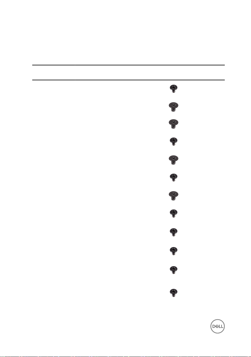
Screw list
Table 1. : Screw list
Component Secured to Screw
Back-light cable System board M3X4 1
Camera Middle frame M2X3 2
Chassis fan System board M2X3 4
Converter board Middle frame M3X4 3
Display Built-in
Self Test button
Hard-drive cage Middle frame M3X4 4
Hard-drive
interposer
I/O panel Middle frame M3X4 4
I/O board I/O-board panel M3X4 1
Middle frame M2X3 2
Hard-drive cage M2X3 4
type
QuantityScrew image
Inner frame
(touch screen)
Inner frame
(non-touch
screen)
Memory fan Middle frame M3X4 4
14
Middle frame M3X4 14
Middle frame M3X4 20
Page 15
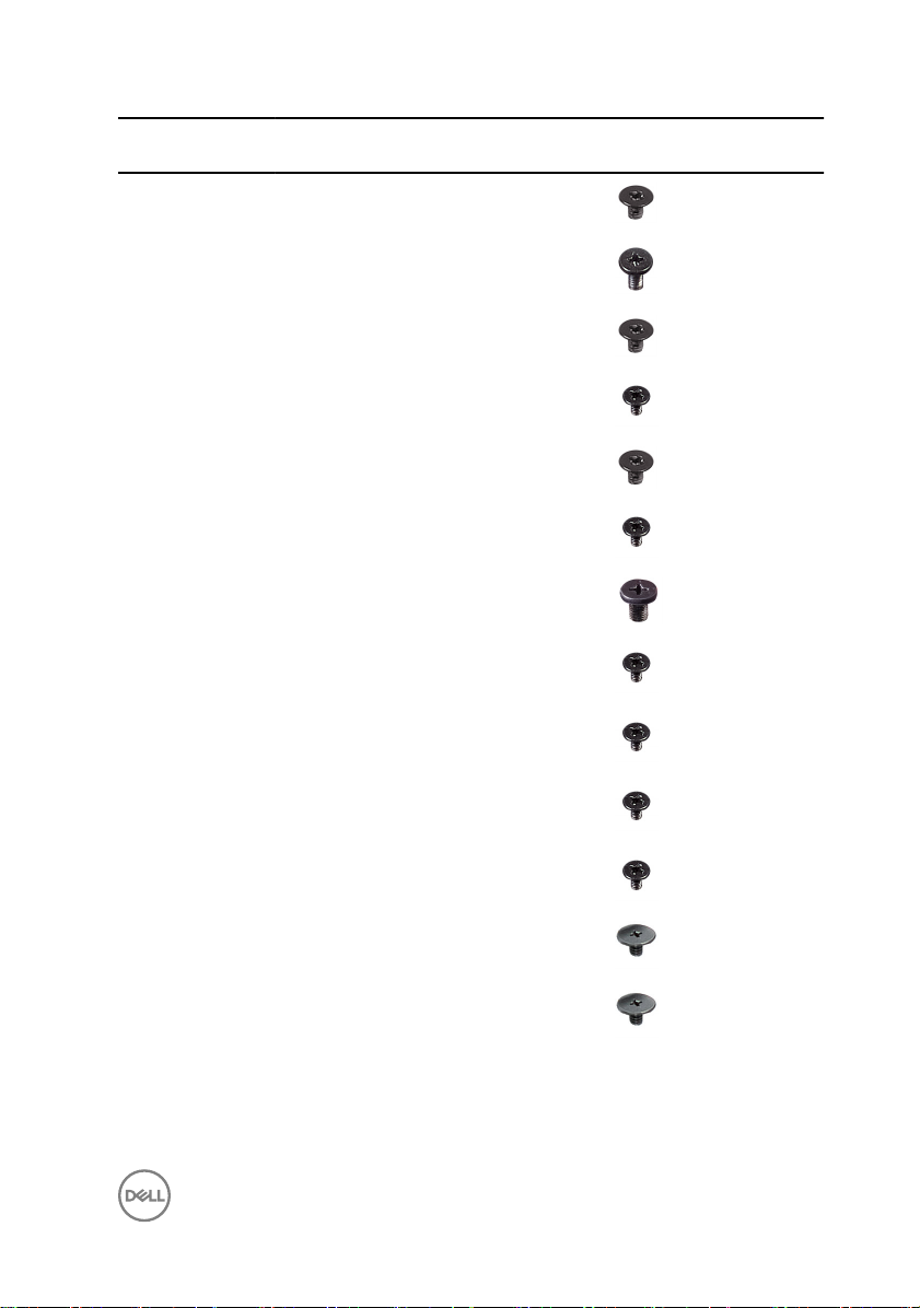
Component Secured to Screw
Media-card
reader shield
Middle frame Display M2X4 7
Middle frame Display M2X3 6
Middle frame M2X3 2
type
QuantityScrew image
Power-supply
unit
Power-button
board shield
Processor heatsink
Stand Middle frame M4X6 6
System-board
shield
System board Middle frame M3X4 12
Speakers Middle frame M3X4 8
USB dongle port I/O panel M3X4 3
Wireless card
shield
Wireless card
bracket
Middle frame M3X4 5
Middle frame M2X3 2
Middle frame M3X4 1
System board M3X4 3
System board M2X2.5 2
System board M2X2.5 1
15
Page 16

After working inside your computer
CAUTION: Leaving stray or loose screws inside your computer may severely
damage your computer.
1 Replace all screws and ensure that no stray screws remain inside your computer.
2 Connect any external devices, peripherals, or cables you removed before working
on your computer.
3 Replace any media cards, discs, or any other parts that you removed before
working on your computer.
4 Connect your computer and all attached devices to their electrical outlets.
5 Turn on your computer.
16
Page 17
Technical overview
WARNING: Before working inside your computer, read the safety
information that shipped with your computer and follow the steps in Before
working inside your computer. After working inside your computer, follow
the instructions in After working inside your computer. For more safety best
practices, see the Regulatory Compliance home page at
regulatory_compliance.
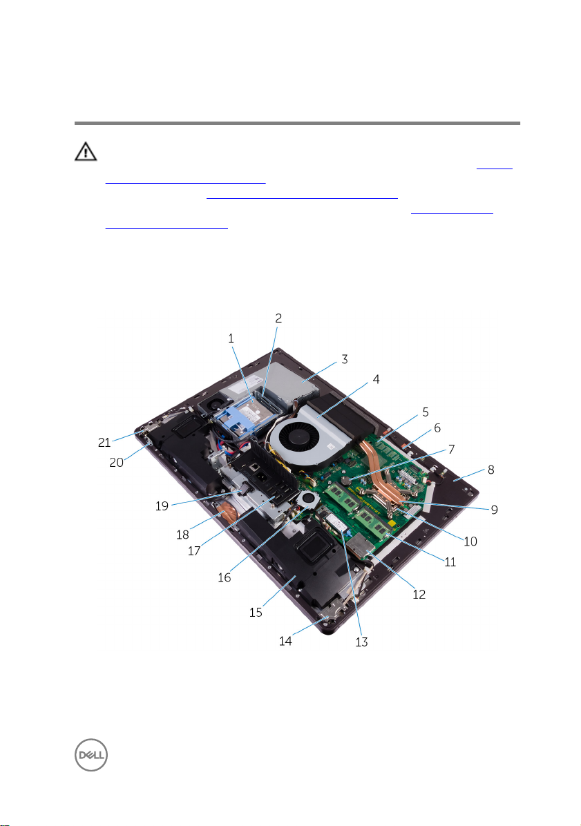
Inside view of your computer (touch screen)
www.dell.com/
Figure 1. : Inside view of your computer
1
2.5-inch hard drive 2 hard-drive cage
3 power-supply unit 4 chassis fan
17
Page 18

5 system board 6 microphone module
7 coin-cell battery 8 middle frame
9 processor heat-sink 10 processor
11 memory module 12 wireless-card shield
13 solid-state drive (M.2) 14 I/O board
15 speakers (2) 16 memory fan
17 I/O panel 18 camera
19 USB dongle-port 20 display built-in self test button
21 power-button board
board
18
Page 19
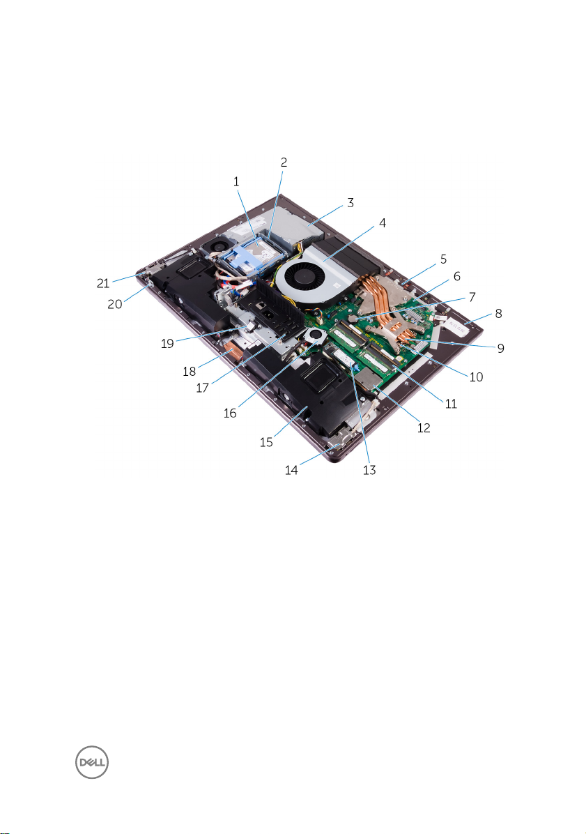
Inside view of your computer (non-touch screen)
Figure 2. : Inside view of your computer (non-touch screen)
1
2.5-inch hard drive 2 hard-drive cage
3 power-supply unit 4 chassis fan
5 microphone module 6 system board
7 coin-cell battery 8 middle frame
9 processor heat-sink 10 processor
11 memory module 12 wireless-card shield
13 solid-state drive (M.2) 14 I/O board
15 speakers (2) 16 memory fan
17 I/O panel 18 camera
19 USB dongle-port 20 display built-in self test button
board
19
Page 20
21 power-button board
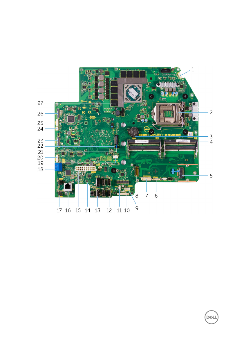
System Board Components
1 microphone cable connector 2 processor socket
3 coin-cell battery connector 4 memory module slot
5 wireless-card slot 6 audio-cable connector
7 media-card connector 8 SSD-card connector (M.2)
9 speaker cable connector 10 converter-board cable connector
11 memory-fan cable connector 12 USB 3.0 ports (4)
13 HDMI port 14 display port
15 power-supply unit cable connector 16 network port
17 Thunderbolt 3 (USB Type-C) ports
(2)
20
18 SATA-card slot
Page 21

19 chassis-fan cable connector 20 SATA power connector
21 password clear jumper 22 CMOS clear jumper
23 side USB connector 24 touch cable connector
25 camera connector 26 display connector
27 thermal pads (on computers shipped
with integrated graphics)
21
Page 22
Removing the USB dongle-bay cover
WARNING: Before working inside your computer, read the safety
information that shipped with your computer and follow the steps in Before
working inside your computer. After working inside your computer, follow
the instructions in After working inside your computer. For more safety best
practices, see the Regulatory Compliance home page at
regulatory_compliance.
Procedure
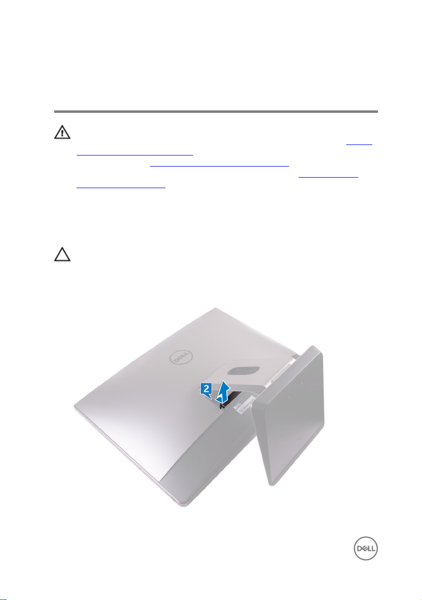
CAUTION: Place the computer on a at, soft and clean surface to avoid
scratching the display.
1 Place the computer face down.
2 Press and pull the USB dongle-bay cover.
www.dell.com/
22
Page 23

Replacing the USB dongle-bay cover
WARNING: Before working inside your computer, read the safety
information that shipped with your computer and follow the steps in Before
working inside your computer. After working inside your computer, follow
the instructions in After working inside your computer. For more safety best
practices, see the Regulatory Compliance home page at
regulatory_compliance.
Procedure
Align the tabs on the USB dongle-bay cover into the slots on the back cover and
snap the USB dongle-bay cover into place.
www.dell.com/
23
Page 24

Removing the back cover
WARNING: Before working inside your computer, read the safety
information that shipped with your computer and follow the steps in Before
working inside your computer. After working inside your computer, follow
the instructions in After working inside your computer. For more safety best
practices, see the Regulatory Compliance home page at
regulatory_compliance.
Prerequisites
Remove the USB dongle-bay cover.
Procedure (touch screen)
1 Loosen the captive screws that secure the back cover to the inner frame.
www.dell.com/
24
Page 25
2 Slide the back cover towards the top of the computer and lift the back cover o
the inner frame.
25
Page 26
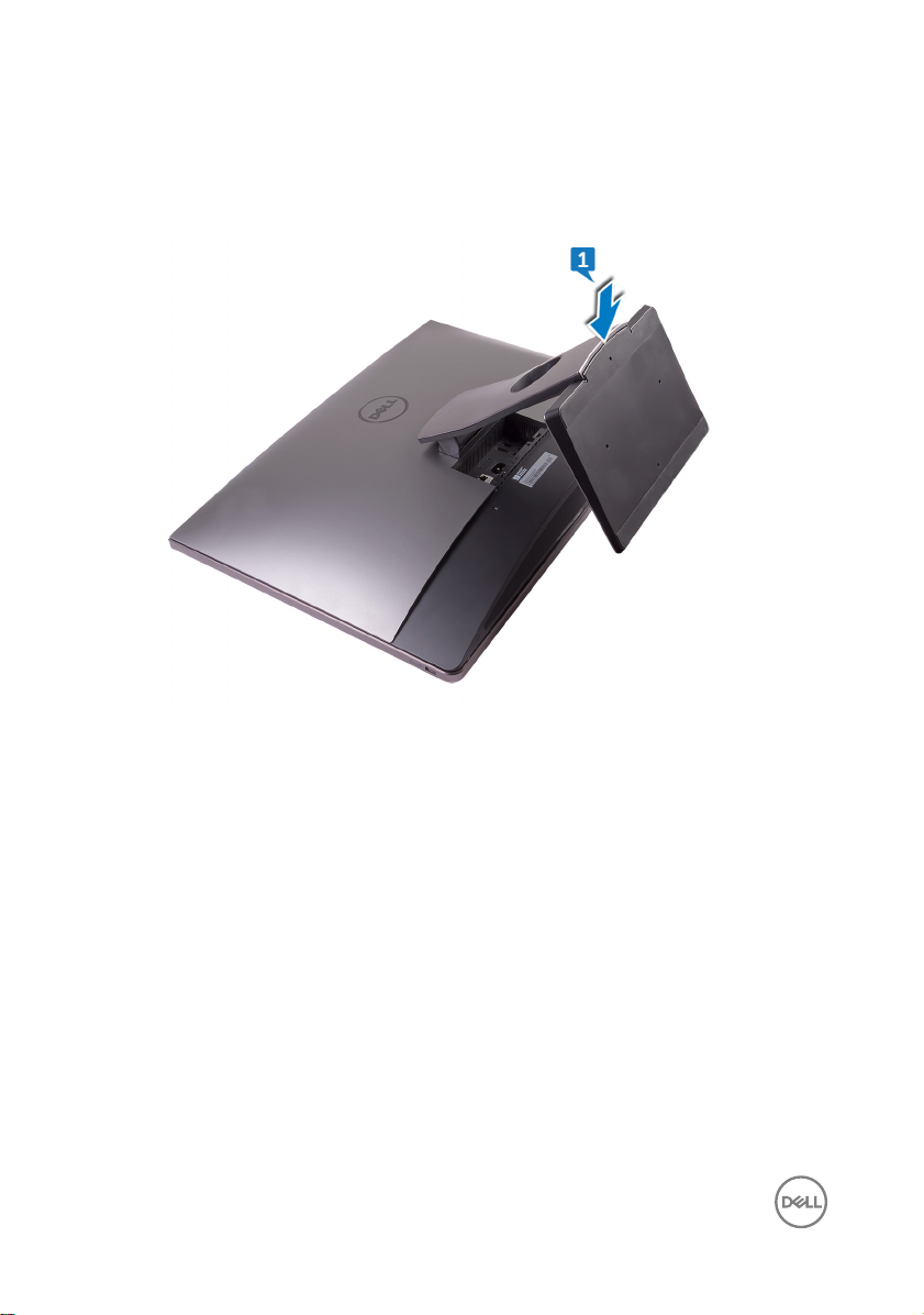
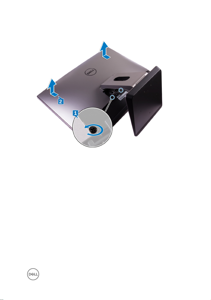
Procedure (non-touch screen)
1 Push the stand down.
2 Loosen the captive screws that secure the back cover to the inner frame.
26
Page 27
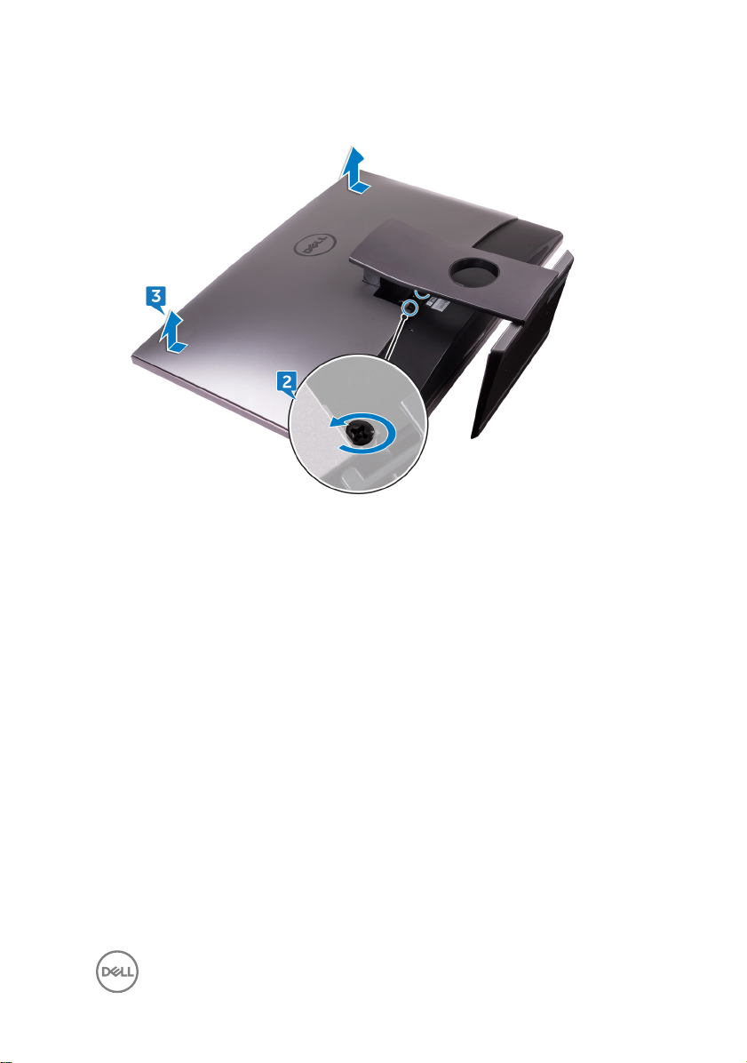
3 Slide the back cover towards the top of the computer and lift the back cover o
the inner frame.
27
Page 28

Replacing the back cover
WARNING: Before working inside your computer, read the safety
information that shipped with your computer and follow the steps in Before
working inside your computer. After working inside your computer, follow
the instructions in After working inside your computer. For more safety best
practices, see the Regulatory Compliance home page at
regulatory_compliance.
Procedure
1 Align the tabs on the back cover with the slots on the inner frame.
2 Slide the back cover towards the bottom of the computer and snap the back
cover in place.
3 Tighten the captive screws that secure the back cover to the inner frame.
Post-requisites
Replace the USB dongle-bay cover.
www.dell.com/
28
Page 29
Removing the memory modules
WARNING: Before working inside your computer, read the safety
information that shipped with your computer and follow the steps in Before
working inside your computer. After working inside your computer, follow
the instructions in After working inside your computer. For more safety best
practices, see the Regulatory Compliance home page at
regulatory_compliance.
Prerequisites
1 Remove the USB dongle-bay cover.
2 Remove the back cover.
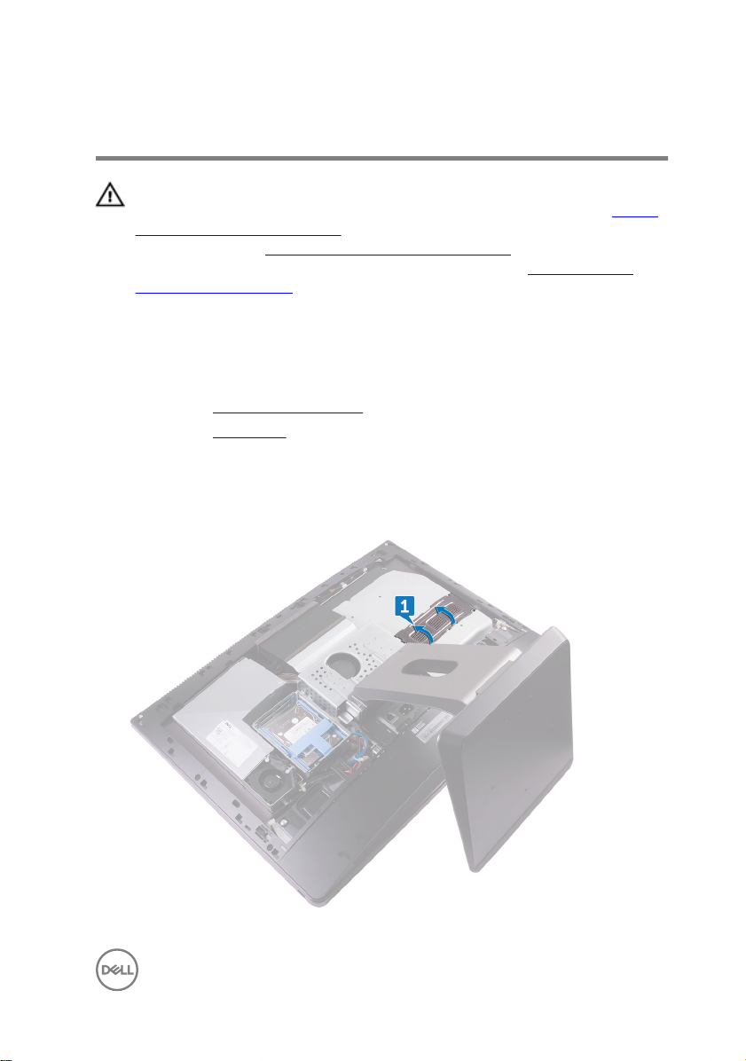
Procedure
1 Using the tabs pry open the memory-module shield.
www.dell.com/
29
Page 30
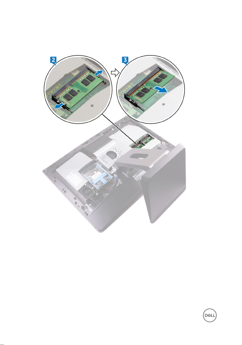
2 Using your ngertips, spread apart the securing clips at each end of the
memory-module slot until the memory module pops up.
3 Slide and remove the memory module from the memory-module slot.
30
Page 31

Replacing the memory modules
WARNING: Before working inside your computer, read the safety
information that shipped with your computer and follow the steps in Before
working inside your computer. After working inside your computer, follow
the instructions in After working inside your computer. For more safety best
practices, see the Regulatory Compliance home page at
regulatory_compliance.
Procedure
1 Align the notch on the memory module with the tab on the memory-module slot.
2 Slide the memory module rmly into the slot at an angle and press the memory
module down until it clicks into place.
NOTE: If you do not hear the click, remove the memory module and
reinstall it.
3 Slide the tabs on the memory-module shield into the slots on the system-board
shield and snap it into place.
Post-requisites
1 Replace the back cover.
2 Replace the USB dongle-bay cover.
www.dell.com/
31
Page 32

Removing the hard drive
WARNING: Before working inside your computer, read the safety
information that shipped with your computer and follow the steps in Before
working inside your computer. After working inside your computer, follow
the instructions in After working inside your computer. For more safety best
practices, see the Regulatory Compliance home page at
regulatory_compliance.
CAUTION: Hard drives are fragile. Exercise care when handling the hard
drive.
CAUTION: To avoid data loss, do not remove the hard drive while the
computer is in sleep or on state.
Prerequisites
1 Remove the USB dongle-bay cover.
2 Remove the back cover.
Procedure
1 Press down on the straps on the hard-drive assembly.
www.dell.com/
32
Page 33

2 Using the straps on the hard-drive assembly, gently push and lift the hard-drive
assembly out of the hard-drive cage.
3 Pry the hard-drive bracket to release the tabs on the bracket from the slots on
the hard drive.
33
Page 34

4 Slide the hard drive o the hard-drive bracket.
NOTE: Note the orientation of the hard drive so that you can replace it
correctly.
34
Page 35

Replacing the hard drive
WARNING: Before working inside your computer, read the safety
information that shipped with your computer and follow the steps in Before
working inside your computer. After working inside your computer, follow
the instructions in After working inside your computer. For more safety best
practices, see the Regulatory Compliance home page at
regulatory_compliance.
CAUTION: Hard drives are fragile. Exercise care when handling the hard
drive.
Procedure
NOTE: The hard drive installed on the top slot is the primary hard drive. In
case, there is only one hard drive, install it on the top slot.
1 Place the hard drive into the hard-drive bracket and align the tabs on the bracket
with the slots on the hard drive.
2 Snap the hard-drive bracket into the hard drive.
3 With the straps facing up, align the hard-drive assembly with the slots on the
hard-drive cage.
4 Using the straps pull the hard-drive assembly towards the back of the computer
till it snaps into the hard-drive interposer.
www.dell.com/
Post-requisites
1 Replace the back cover.
2 Replace the USB dongle-bay cover.
35
Page 36

Removing the system-board shield
WARNING: Before working inside your computer, read the safety
information that shipped with your computer and follow the steps in Before
working inside your computer. After working inside your computer, follow
the instructions in After working inside your computer. For more safety best
practices, see the Regulatory Compliance home page at
regulatory_compliance.
Prerequisites
1 Remove the USB dongle-bay cover.
2 Remove the back cover.
Procedure
1 Remove the three screws (M3X4) that secure the system-board shield to the
middle frame.
www.dell.com/
36
Page 37

2 Lift the system-board shield o the middle frame.
37
Page 38

Replacing the system-board shield
WARNING: Before working inside your computer, read the safety
information that shipped with your computer and follow the steps in Before
working inside your computer. After working inside your computer, follow
the instructions in After working inside your computer. For more safety best
practices, see the Regulatory Compliance home page at
regulatory_compliance.
Procedure
1 Align the screw holes on the system-board shield with the screw holes on the
middle frame.
2 Replace the three screws (M3X4) that secure the system-board shield to the
middle frame.
Post-requisites
1 Replace the back cover.
2 Replace the USB dongle-bay cover.
www.dell.com/
38
Page 39

Removing the memory fan
WARNING: Before working inside your computer, read the safety
information that shipped with your computer and follow the steps in Before
working inside your computer. After working inside your computer, follow
the instructions in After working inside your computer. For more safety best
practices, see the Regulatory Compliance home page at
regulatory_compliance.
Prerequisites
1 Remove the USB dongle-bay cover.
2 Remove the back cover.
3 Remove the system-board shield.
Procedure
1 Remove the four screws (M2X3) that secure the memory fan to the middle
frame.
2 Gently lift the memory fan from the system board.
www.dell.com/
39
Page 40

3 Disconnect the memory fan cable from the system board.
40
Page 41

Replacing the memory fan
WARNING: Before working inside your computer, read the safety
information that shipped with your computer and follow the steps in Before
working inside your computer. After working inside your computer, follow
the instructions in After working inside your computer. For more safety best
practices, see the Regulatory Compliance home page at
regulatory_compliance.
Procedure
1 Connect the memory fan cable to the system board.
2 Align the screw holes on the memory fan with the screw holes on the system
board.
3 Replace the four screws (M2X3) that secure the memory fan to the system
board.
Post-requisites
1 Replace the system-board shield.
2 Replace the back cover.
3 Replace the USB dongle-bay cover.
www.dell.com/
41
Page 42

Removing the processor heatsink
WARNING: Before working inside your computer, read the safety
information that shipped with your computer and follow the steps in Before
working inside your computer. After working inside your computer, follow
the instructions in After working inside your computer. For more safety best
practices, see the Regulatory Compliance home page at
regulatory_compliance.
CAUTION: For maximum cooling of the processor, do not touch the heat
transfer areas on the heat sink. The oils in your skin can reduce the heat
transfer capability of the thermal grease.
Prerequisites
1 Remove the USB dongle-bay cover.
2 Remove the back cover.
3 Remove the system-board shield.
Procedure for computers with integrated graphics
www.dell.com/
NOTE: Depending on the conguration you ordered, the appearance of the
processor heat-sink and the number of screws may dier.
1 In sequential order (indicated on the heat sink), loosen the captive screws that
secure the processor heat-sink to the system board.
2 Remove the screw (M3X4) that secures the processor heat-sink fan to the
middle frame.
42
Page 43

3 Lift the processor heat-sink o the system board.
Procedure for computers with discrete graphics
NOTE: Depending on the conguration you ordered, the appearance of the
processor heat-sink and the number of screws may dier.
1 In sequential order (indicated on the heat sink), loosen the captive screws that
secure the processor heat-sink to the system board.
2 Remove the screw (M3X4) that secures the processor heat-sink fan to the
middle frame.
43
Page 44

3 Lift the processor heat-sink o the system board.
NOTE: Computers that support AMD R9 M470X and AMD R9 M485X
graphics conguration are shipped with 8 captive screws
NOTE: Computers that support AMD Radeon Pro WX7100, AMD
Radeon Pro WX4150, and AMD Radeon RX470 graphics are shipped
with 7 captive screws
44
Page 45

Replacing the processor heatsink
WARNING: Before working inside your computer, read the safety
information that shipped with your computer and follow the steps in Before
working inside your computer. After working inside your computer, follow
the instructions in After working inside your computer. For more safety best
practices, see the Regulatory Compliance home page at
regulatory_compliance.
CAUTION: For maximum cooling of the processor, do not touch the heat
transfer areas on the heat sink. The oils in your skin can reduce the heat
transfer capability of the thermal grease.
Procedure
1 Align the captive screws on the processor heat-sink with the screw holes on the
system board.
2 In sequential order (indicated on the processor heat-sink), tighten the captive
screws that secure the processor heat-sink to the system board.
3 Replace the screw (M3X4) that secures the processor heat-sink fan to the
middle frame.
www.dell.com/
Post-requisites
1 Replace the system-board shield.
2 Replace the back cover.
3 Replace the USB dongle-bay cover.
45
Page 46

Removing the processor
WARNING: Before working inside your computer, read the safety
information that shipped with your computer and follow the steps in Before
working inside your computer. After working inside your computer, follow
the instructions in After working inside your computer. For more safety best
practices, see the Regulatory Compliance home page at
regulatory_compliance.
Prerequisites
1 Remove the USB dongle-bay cover.
2 Remove the back cover.
3 Remove the system-board shield.
4 Remove the processor heat-sink.
Procedure
1 Press the release-lever down and then pull it outwards to release it from the
securing tab.
2 Extend the release-lever completely to open the processor cover.
www.dell.com/
46
Page 47

3 Gently lift the processor and remove it from the processor socket.
47
Page 48

Replacing the processor
WARNING: Before working inside your computer, read the safety
information that shipped with your computer and follow the steps in Before
working inside your computer. After working inside your computer, follow
the instructions in After working inside your computer. For more safety best
practices, see the Regulatory Compliance home page at
regulatory_compliance.
CAUTION: If either the processor or the heat sink is replaced, use the
thermal grease provided in the kit to ensure that thermal conductivity is
achieved.
NOTE: A new processor ships with a thermal pad in the package. In some
cases, the processor may ship with the thermal pad attached to it.
Procedure
1 Ensure that the release lever on the processor socket is fully extended in the
open position.
CAUTION: The pin-1 corner of the processor has a triangle that aligns
with the triangle on the pin-1 corner on the processor socket. When the
processor is properly seated, all four corners are aligned at the same
height. If one or more corners of the processor are higher than the
others, the processor is not seated properly.
2 Align the notches on the processor with the tabs on the processor socket and
place the processor in the processor socket.
www.dell.com/
CAUTION: Ensure that the processor-cover notch is positioned
underneath the alignment post.
3 When the processor is fully seated in the socket, close the processor cover.
48
Page 49

4 Pivot the release-lever down and place it under the tab on the processor cover.
Post-requisites
1 Replace the processor heat-sink.
2 Replace the system-board shield.
3 Replace the back cover.
4 Replace the USB dongle-bay cover.
49
Page 50

Removing the coin-cell battery
WARNING: Before working inside your computer, read the safety
information that shipped with your computer and follow the steps in Before
working inside your computer. After working inside your computer, follow
the instructions in After working inside your computer. For more safety best
practices, see the Regulatory Compliance home page at
regulatory_compliance.
CAUTION: Removing the coin-cell battery resets the BIOS setup program’s
settings to default. It is recommended that you note the BIOS setup
program’s settings before removing the coin-cell battery.
Prerequisites
1 Remove the USB dongle-bay cover.
2 Remove the back cover.
3 Remove the system-board shield.
www.dell.com/
50
Page 51

Procedure
Using a plastic scribe, gently push the tabs on the coin-cell battery socket and lift the
coin-cell battery o it’s slot on the system board.
51
Page 52

Replacing the coin-cell battery
WARNING: Before working inside your computer, read the safety
information that shipped with your computer and follow the steps in Before
working inside your computer. After working inside your computer, follow
the instructions in After working inside your computer. For more safety best
practices, see the Regulatory Compliance home page at
regulatory_compliance.
Procedure
With the positive-side facing up, insert the coin-cell battery into the battery socket
and press down the battery into place.
Post-requisites
1 Replace the system-board shield.
2 Replace the back cover.
3 Replace the USB dongle-bay cover.
www.dell.com/
52
Page 53

Removing the solid-state drive
WARNING: Before working inside your computer, read the safety
information that shipped with your computer and follow the steps in Before
working inside your computer. After working inside your computer, follow
the instructions in After working inside your computer. For more safety best
practices, see the Regulatory Compliance home page at
regulatory_compliance.
CAUTION: Solid-state drives are fragile. Exercise care when handling the
solid-state drive.
CAUTION: To avoid data loss, do not remove the solid-state drive while the
computer is in sleep or on state.
Prerequisites
1 Remove the USB dongle-bay cover.
2 Remove the back cover.
3 Remove the system-board shield.
Procedure
1 Open the securing clip that secures the solid-state drive to the system board.
www.dell.com/
53
Page 54

2 Slide and remove the solid-state drive from the solid-state drive slot.
54
Page 55

Replacing the solid-state drive
WARNING: Before working inside your computer, read the safety
information that shipped with your computer and follow the steps in Before
working inside your computer. After working inside your computer, follow
the instructions in After working inside your computer. For more safety best
practices, see the Regulatory Compliance home page at
regulatory_compliance.
CAUTION: Solid-state drives are fragile. Exercise care when handling the
solid-state drive.
Procedure
1 Align the notch on the solid-state drive with the tab on the solid-state drive slot.
2 Slide the solid-state drive into the solid-state drive slot.
3 Secure the solid-state drive to the system board using the securing clip.
Post-requisites
1 Replace the system-board shield.
2 Replace the back cover.
3 Replace the USB dongle-bay cover.
www.dell.com/
55
Page 56

Removing the wireless card
WARNING: Before working inside your computer, read the safety
information that shipped with your computer and follow the steps in Before
working inside your computer. After working inside your computer, follow
the instructions in After working inside your computer. For more safety best
practices, see the Regulatory Compliance home page at
regulatory_compliance.
Prerequisites
1 Remove the USB dongle-bay cover.
2 Remove the back cover.
3 Remove the system-board shield.
Procedure
1 Remove the antenna cables from the securing clip.
2 Remove the two screws (M2X2.5) that secure the wireless-card shield to the
system board.
3 Lift the wireless-card shield o the system board.
4 Remove the screw (M2X2.5) that secures the wireless-card bracket and the
wireless card to the system board.
5 Lift the wireless-card bracket o the wireless card.
6 Disconnect the antenna cables from the wireless card.
www.dell.com/
56
Page 57

7 Slide and remove the wireless card out of the wireless-card slot.
57
Page 58

Replacing the wireless card
WARNING: Before working inside your computer, read the safety
information that shipped with your computer and follow the steps in Before
working inside your computer. After working inside your computer, follow
the instructions in After working inside your computer. For more safety best
practices, see the Regulatory Compliance home page at
regulatory_compliance.
Procedure
CAUTION: To avoid damaging the wireless card, do not place any cables
under it.
1 Align the notch on the wireless card with the tab on the wireless-card slot and
slide the wireless card into the wireless-card slot.
2 Route the antenna cable through the routing guide.
3 Connect the antenna cables to the wireless card.
The following table provides the antenna-cable color scheme for the wireless
card supported by your computer:
Table 2. : Wirelesscard colour scheme
Connectors on the wireless card Antenna-cable color
www.dell.com/
Main (white triangle) White
Auxiliary (black triangle) Black
4 Press down the other end of the wireless card and align the screw hole on the
wireless-card bracket and wireless card with the screw hole on the system
board.
5 Replace the screw (M2X2.5) that secures the wireless-card bracket and the
wireless card to the system board.
6 Align the screw holes on the wireless-card shield with the screw holes on the
system board.
7 Replace the two screws (M2X2.5) that secures the wireless-card shield to
system board.
58
Page 59

8 Route the antenna cables through the securing clip.
Post-requisites
1 Replace the system-board shield.
2 Replace the back cover.
3 Replace the USB dongle-bay cover.
59
Page 60

Removing the stand
WARNING: Before working inside your computer, read the safety
information that shipped with your computer and follow the steps in Before
working inside your computer. After working inside your computer, follow
the instructions in After working inside your computer. For more safety best
practices, see the Regulatory Compliance home page at
regulatory_compliance.
Prerequisites
1 Remove the USB dongle-bay cover.
2 Remove the back cover.
Procedure
NOTE: The process for removing and replacing the stand will be same for
articulating stand and pedestal stand.
1 Remove the six screws (M4X6) that secure the stand to the middle frame.
www.dell.com/
60
Page 61

2 Lift the stand o the computer.
61
Page 62

Replacing the stand
WARNING: Before working inside your computer, read the safety
information that shipped with your computer and follow the steps in Before
working inside your computer. After working inside your computer, follow
the instructions in After working inside your computer. For more safety best
practices, see the Regulatory Compliance home page at
regulatory_compliance.
Procedure
1 Align the screw holes on the stand with the screw holes on the middle frame.
2 Replace the six screws (M4X6) that secure the stand to the middle frame.
Post-requisites
1 Replace the back cover.
2 Replace the USB dongle-bay cover.
www.dell.com/
62
Page 63

Removing the chassis fan
WARNING: Before working inside your computer, read the safety
information that shipped with your computer and follow the steps in Before
working inside your computer. After working inside your computer, follow
the instructions in After working inside your computer. For more safety best
practices, see the Regulatory Compliance home page at
regulatory_compliance.
Prerequisites
1 Remove the USB dongle-bay cover.
2 Remove the back cover.
3 Remove the stand.
4 Remove the system-board shield.
Procedure
1 Remove the power-supply unit cable from the routing guides on the chassis fan.
www.dell.com/
63
Page 64

2 Disconnect the power-supply unit cable from its connector on the system board.
3 Disconnect the chassis fan cable from the system board.
4 Remove the four screws (M3X4) that secure the chassis fan to the middle
frame.
64
Page 65

5 Lift the chassis fan along with its cable o the middle frame.
65
Page 66

Replacing the chassis fan
WARNING: Before working inside your computer, read the safety
information that shipped with your computer and follow the steps in Before
working inside your computer. After working inside your computer, follow
the instructions in After working inside your computer. For more safety best
practices, see the Regulatory Compliance home page at
regulatory_compliance.
Procedure
1 Align the screw holes on the chassis fan with the screw holes on the middle
frame.
2 Replace the screws (M3X4) that secure the chassis fan to the middle frame.
3 Connect the chassis fan cable to the system board.
4 Connect the power-supply unit cable to its connector on the system board.
5 Route the power-supply unit cable through the routing guides on the chassis fan.
Post-requisites
1 Replace the system-board shield.
2 Replace the stand.
3 Replace the back cover.
4 Replace the USB dongle-bay cover.
www.dell.com/
66
Page 67

Removing the power-supply unit
WARNING: Before working inside your computer, read the safety
information that shipped with your computer and follow the steps in Before
working inside your computer. After working inside your computer, follow
the instructions in After working inside your computer. For more safety best
practices, see the Regulatory Compliance home page at
regulatory_compliance.
Prerequisites
1 Remove the USB dongle-bay cover.
2 Remove the back cover.
3 Remove the stand.
Procedure
1 Remove the power-supply unit cable from the routing guides on the chassis fan.
2 Disconnect the power-supply unit cable from its connector on the system board.
3 Press the securing clip to release the power-supply indicator cable from its
connector.
4 Press the securing clip to release the power-supply fan cable from its connector.
www.dell.com/
67
Page 68

5 Open the securing clips and release the cables.
6 Remove the ve screws (M3X4) that secure the power-supply unit to the middle
cover.
68
Page 69

7 Lift the power-supply unit with the cable o the middle cover.
69
Page 70

Replacing the power-supply unit
WARNING: Before working inside your computer, read the safety
information that shipped with your computer and follow the steps in Before
working inside your computer. After working inside your computer, follow
the instructions in After working inside your computer. For more safety best
practices, see the Regulatory Compliance home page at
regulatory_compliance.
Procedure
1 Align the screw holes on the power-supply unit with the screw holes on the
middle cover.
2 Replace the ve screws (M3X4) that secure the power-supply unit to the middle
cover.
3 Route the cables through the guide and close the clip to secure the cables.
4 Connect the power-supply indicator cable and power-supply fan cable to their
respective connectors.
5 Route the power-supply unit cable through the routing guides on chassis fan.
6 Connect the power-supply unit cable to its connector on the system board.
Post-requisites
www.dell.com/
1 Replace the stand.
2 Replace the back cover.
3 Replace the USB dongle-bay cover.
70
Page 71

Removing the inner frame
WARNING: Before working inside your computer, read the safety
information that shipped with your computer and follow the steps in Before
working inside your computer. After working inside your computer, follow
the instructions in After working inside your computer. For more safety best
practices, see the Regulatory Compliance home page at
regulatory_compliance.
Prerequisites
1 Remove the USB dongle-bay cover.
2 Remove the back cover.
3 Remove the stand.
www.dell.com/
71
Page 72

Procedure
1 Remove the screws (M3X4) that secure the inner frame to the middle frame.
NOTE: Touch screen has 14 screws and non-touch screen has 20
screws that secure the inner frame to the middle frame.
72
Page 73

2 Gently pry the inner frame from the sides and lift it o the middle frame.
73
Page 74

Replacing the inner frame
WARNING: Before working inside your computer, read the safety
information that shipped with your computer and follow the steps in Before
working inside your computer. After working inside your computer, follow
the instructions in After working inside your computer. For more safety best
practices, see the Regulatory Compliance home page at
regulatory_compliance.
Procedure
1 Align the screw holes on the inner frame with the screw holes on the middle
frame.
2 Replace the screws (M3X4) that secure the inner frame to the middle frame.
NOTE: Touch screen has 14 screws and non-touch screen has 20
screws that secure the inner frame to the middle frame.
Post-requisites
1 Replace the stand.
2 Replace the back cover.
3 Replace the USB dongle-bay cover.
www.dell.com/
74
Page 75

Removing the display built-in self test button board
WARNING: Before working inside your computer, read the safety
information that shipped with your computer and follow the steps in Before
working inside your computer. After working inside your computer, follow
the instructions in After working inside your computer. For more safety best
practices, see the Regulatory Compliance home page at
regulatory_compliance.
Prerequisites
1 Remove the USB dongle-bay cover.
2 Remove the back cover.
3 Remove the stand.
4 Remove the inner frame.
Procedure
1 Remove the power-button cable from the routing guide on the power-button
board shield.
2 Remove the two screws (M2X3) that secure the power-button board shield to
the middle frame.
3 Lift the power-button board shield o the middle frame.
4 Disconnect the Display Built-in Self Test button cable from the power-button
board.
5 Remove the Display Built-in Self Test button cable from the routing guide on the
middle frame.
6 Remove the two screws (M2X3) that secure the Display Built-in Self Test button
board to the middle frame.
www.dell.com/
75
Page 76

7 Lift the Display Built-in Self Test button board o the middle frame.
76
Page 77

Replacing the display built-in self test button board
WARNING: Before working inside your computer, read the safety
information that shipped with your computer and follow the steps in Before
working inside your computer. After working inside your computer, follow
the instructions in After working inside your computer. For more safety best
practices, see the Regulatory Compliance home page at
regulatory_compliance.
Procedure
1 Place the Display Built-in Self Test button board on the middle frame.
2 Align the screw holes on the Display Built-in Self Test button board with the
screw holes on the middle frame.
3 Replace the two screws (M2X3) that secure the Display Built-in Self Test button
board to the middle frame.
4 Route the Display Built-in Self Test button cable through the routing guides.
5 Connect the Display Built-in Self Test button cable to the power-button board.
6 Place the power-button board shield on the middle frame.
7 Align the screw holes on the power-button board shield with the screw holes on
the middle frame.
8 Replace the two screws (M2X3) that secure the power-button board shield to
the middle frame.
9 Route the power-button cable through the routing guides on the power-button
board shield..
www.dell.com/
Post-requisites
1 Replace the inner frame.
2 Replace the stand.
3 Replace the back cover.
4 Replace the USB dongle-bay cover.
77
Page 78

Removing the microphones
WARNING: Before working inside your computer, read the safety
information that shipped with your computer and follow the steps in Before
working inside your computer. After working inside your computer, follow
the instructions in After working inside your computer. For more safety best
practices, see the Regulatory Compliance home page at
regulatory_compliance.
Prerequisites
1 Remove the USB dongle-bay cover.
2 Remove the back cover.
3 Remove the system-board shield.
4 Remove the stand.
5 Remove the inner frame.
Procedure
1 Disconnect the microphone cable from the system board and release it from the
routing guides on the middle frame.
2 Remove the four screws (M2X2.2) that secure the microphone module to the
middle frame.
3 Release it from the routing guides on the middle frame.
www.dell.com/
78
Page 79

4 Using a plastic scribe, carefully pry and lift the microphone modules (4) with the
cable o the slots on the middle frame.
79
Page 80

Replacing the microphones
WARNING: Before working inside your computer, read the safety
information that shipped with your computer and follow the steps in Before
working inside your computer. After working inside your computer, follow
the instructions in After working inside your computer. For more safety best
practices, see the Regulatory Compliance home page at
regulatory_compliance.
Procedure
1 Align the microphone modules (4) with their slots on the middle frame.
2 Route the cable through the routing guides on middle frame.
3 Replace the four screws (M2X2.2) that secures the microphone module to the
middle frame.
4 Connect the microphone cable to the system board.
Post-requisites
1 Replace the inner frame.
2 Replace the stand.
3 Replace the system-board shield.
4 Replace the back cover.
5 Replace the USB dongle-bay cover.
www.dell.com/
80
Page 81

Removing the I/O panel
WARNING: Before working inside your computer, read the safety
information that shipped with your computer and follow the steps in Before
working inside your computer. After working inside your computer, follow
the instructions in After working inside your computer. For more safety best
practices, see the Regulatory Compliance home page at
regulatory_compliance.
Prerequisites
1 Remove the USB dongle-bay cover.
2 Remove the back cover.
3 Remove the stand.
4 Remove the system-board shield.
5 Remove the inner frame.
Procedure
1 Press the securing clip to release the power button cable from its connector.
2 Press the securing clip to release the diagnostic button and light cable from its
connector.
3 Disconnect the USB dongle cable from the system board.
4 Remove the four screws (M3X4) that secure the I/O panel to the middle frame
and system board.
www.dell.com/
81
Page 82

5 Lift the I/O panel o the middle frame.
6 Remove USB-dongle port.
7 Remove the Diagnostic light button board.
82
Page 83

Replacing the I/O panel
WARNING: Before working inside your computer, read the safety
information that shipped with your computer and follow the steps in Before
working inside your computer. After working inside your computer, follow
the instructions in After working inside your computer. For more safety best
practices, see the Regulatory Compliance home page at
regulatory_compliance.
Procedure
1 Replace the Diagnostic light button board.
2 Replace USB-dongle port.
3 Connect the USB-dongle cable to the system board.
4 Align the screw holes on the I/O-board panel with the screw holes on the middle
frame.
5 Replace the four screws (M3X4) that secure the I/O panel to the middle frame
and system board.
6 Connect the diagnostic button and light cable.
7 Connect the power-button cable.
Post-requisites
www.dell.com/
1 Replace the inner frame.
2 Replace the system-board shield.
3 Replace the stand.
4 Replace the back cover.
5 Replace the USB dongle-bay cover.
83
Page 84

Removing the USB-dongle port
WARNING: Before working inside your computer, read the safety
information that shipped with your computer and follow the steps in Before
working inside your computer. After working inside your computer, follow
the instructions in After working inside your computer. For more safety best
practices, see the Regulatory Compliance home page at
regulatory_compliance.
Prerequisites
1 Remove the USB dongle-bay cover.
2 Remove the back cover.
3 Remove the stand.
4 Remove the inner frame.
5 Remove the system-board shield.
6 Remove the I/O panel.
www.dell.com/
84
Page 85

Procedure
1 Remove the three screws (M3X4) that secure the USB dongle port to the I/O
panel.
2 Remove the USB dongle port cable from the routing guide on I/O panel.
85
Page 86

3 Remove the USB dongle port from the I/O panel.
86
Page 87

Replacing the USB-dongle port
WARNING: Before working inside your computer, read the safety
information that shipped with your computer and follow the steps in Before
working inside your computer. After working inside your computer, follow
the instructions in After working inside your computer. For more safety best
practices, see the Regulatory Compliance home page at
regulatory_compliance.
Procedure
1 Route the USB dongle port cable into the slot on I/O panel .
2 Route the USB dongle port cable through the routing guide on I/O panel .
3 Align the screw holes on the USB dongle port to the screw holes on the I/O
panel.
4 Replace the three screws (M3X4) that secure the USB dongle port to the I/O
panel.
Post-requisites
1 Replace the I/O panel.
2 Replace the system-board shield.
3 Replace the inner frame.
4 Replace the stand.
5 Replace the back cover.
6 Replace the USB dongle-bay cover.
www.dell.com/
87
Page 88

Removing the diagnostic light and button board
WARNING: Before working inside your computer, read the safety
information that shipped with your computer and follow the steps in Before
working inside your computer. After working inside your computer, follow
the instructions in After working inside your computer. For more safety best
practices, see the Regulatory Compliance home page at
regulatory_compliance.
Prerequisites
1 Remove the USB dongle-bay cover.
2 Remove the back cover.
3 Remove the stand.
4 Remove the system-board shield.
5 Remove the inner frame.
6 Remove the I/O panel.
www.dell.com/
88
Page 89

Procedure
1 Spread apart the securing tabs to release the I/O-panel bracket from the I/O
panel.
89
Page 90

2 Lift the I/O-panel bracket o the I/O panel.
3 Remove the screw that secures the power diagnostic button and light board to
the I/O-panel bracket.
90
Page 91

4 Lift the power diagnostic button and light board o the I/O-panel bracket.
91
Page 92

Replacing the diagnostic light and button board
WARNING: Before working inside your computer, read the safety
information that shipped with your computer and follow the steps in Before
working inside your computer. After working inside your computer, follow
the instructions in After working inside your computer. For more safety best
practices, see the Regulatory Compliance home page at
regulatory_compliance.
Procedure
1 Align the screw holes on power diagnostic button and light board to the screw
holes on the I/O-panel bracket.
2 Replace the screw that secure the power diagnostic button and light board to
the I/O-panel bracket.
3 Align the tabs on the I/O-panel bracket with the slots on the I/O panel and snap
the I/O-panel bracket in place.
Post-requisites
1 Replace the I/O panel.
2 Replace the inner frame.
3 Replace the system-board shield.
4 Replace the stand.
5 Replace the back cover.
6 Replace the USB dongle-bay cover.
www.dell.com/
92
Page 93

Removing the hard-drive cage
WARNING: Before working inside your computer, read the safety
information that shipped with your computer and follow the steps in Before
working inside your computer. After working inside your computer, follow
the instructions in After working inside your computer. For more safety best
practices, see the Regulatory Compliance home page at
regulatory_compliance.
Prerequisites
1 Remove the USB dongle-bay cover.
2 Remove the back cover.
3 Remove the stand.
4 Remove the hard drive.
5 Remove the system-board shield.
6 Remove the I/O panel.
Procedure
1 Remove the cable from the routing guide on hard-drive cage.
2 Open the securing clips and release the hard drive cables.
3 Disconnect the hard-drive power cable from the system board.
www.dell.com/
93
Page 94

4 Disconnect the hard-drive data cables from the system board.
5 Remove the four screws (M3X4) that connects the hard-drive cage to the
middle frame.
94
Page 95

6 Lift the hard-drive cage o the middle frame.
7 Remove the four screws (M2X3) that connects the interposer to the hard-drive
cage.
8 Disconnect the interposer from the hard-drive cage.
95
Page 96

Replacing the hard-drive cage
WARNING: Before working inside your computer, read the safety
information that shipped with your computer and follow the steps in Before
working inside your computer. After working inside your computer, follow
the instructions in After working inside your computer. For more safety best
practices, see the Regulatory Compliance home page at
regulatory_compliance.
Procedure
1 Align the screw holes on the interposer with the screw holes on the hard-drive
cage.
2 Replace the four screws (M2X3) that connects the interposer to the hard-drive
cage.
3 Align the screw holes on the hard-drive cage to the screw holes on the middle
frame.
4 Replace the four screws (M3X4) that secure the hard-drive cage to the middle
frame.
5 Connect the hard-drive data cables and the hard-drive power cable to the
system board.
NOTE: Connect the blue-colored cable at the top and red-colored cable
to the bottom of the hard-drive age.
6 Route the cables through the guide and close the clip to secure the cables.
www.dell.com/
Post-requisites
1 Replace the I/O panel.
2 Replace the system-board shield.
3 Replace the stand.
4 Replace the hard drive.
5 Replace the back cover.
6 Replace the USB dongle-bay cover.
96
Page 97

Removing the converter board
WARNING: Before working inside your computer, read the safety
information that shipped with your computer and follow the steps in Before
working inside your computer. After working inside your computer, follow
the instructions in After working inside your computer. For more safety best
practices, see the Regulatory Compliance home page at
regulatory_compliance.
Prerequisites
1 Remove the USB dongle-bay cover.
2 Remove the back cover.
3 Remove the stand.
4 Remove the system-board shield.
5 Remove the inner frame.
6 Remove the I/O panel.
Procedure
1 Disconnect the right backlight power cable from the converter board.
2 Disconnect the converter-board cable from the converter board.
www.dell.com/
97
Page 98

3 Disconnect the left backlight power cable from the converter board.
4 Remove the three screws (M3X4) that secure the converter board to the middle
frame.
98
Page 99

5 Lift the converter board o the middle frame.
99
Page 100

Replacing the converter board
WARNING: Before working inside your computer, read the safety
information that shipped with your computer and follow the steps in Before
working inside your computer. After working inside your computer, follow
the instructions in After working inside your computer. For more safety best
practices, see the Regulatory Compliance home page at
regulatory_compliance.
Procedure
1 Align the screw holes on the converter board with the screw holes on the middle
frame.
2 Replace the three screws (M3X4) that secure the converter board to the middle
frame.
3 Connect the converter-board cable to the converter board.
4 Connect the backlight power cables to the converter board.
Post-requisites
1 Replace the I/O panel.
2 Replace the inner frame.
3 Replace the system-board shield.
4 Replace the stand.
5 Replace the back cover.
6 Replace the USB dongle-bay cover.
www.dell.com/
100
 Loading...