

Page 1
Dell™ Latitude™ XT2 XFR
Service Manual
Page 2

Dell™ Latitude™ XT2 XFR Service Manual
Notes, Notices, and Cautions
NOTE: A NOTE indicates important information that helps you make better use of your computer.
CAUTION: A CAUTION indicates either potential damage to hardware or loss of data
and tells you how to avoid the problem.
WARNING: A WARNING indicates a potential for property damage, personal injury, or
death.
Information in this document is subject to change without notice. Som e of the information contained in this
document may not apply to all Dell systems.
© 2009 Dell Inc. All rights reserved.
Reproduction in any manner whatsoever without the written permission of Dell Inc. is strictly forbidden
Trademarks used in this text: Dell, the DELL logo, Latitude, TravelLite, Wi-Fi Catcher, and ExpressCharge, are trademarks
of Dell Inc.; Intel, Pentium, Celeron and Core are registered trademarks of Intel Corporation; Bluetooth is a registered
trademark owned by Bluetooth SIG, Inc. and is used by Dell under license; TouchStrip is a trademark of Zvetco Biometrics,
LLC; Blu-ray Disc is a trademark of the Blu-ray Disc Association; Microsoft, Windows, Windows Server, MS-DOS, Aero,
Windows Vista. and the Windows Vista start button are either trademarks or registered trademarks of Microsoft
Corporation in the United States and/or other countries.
Other trademarks and trade names may be used in this document to refer to either the entities claiming the marks and
names or their products. Dell Inc. disclaims any proprietary inte rest in trademarks and trade names other than its own.
Model P05S
nnnnn 2009 Rev. A00
Page 2 of 94
Version A00-01
Page 3

Dell™ Latitude™ XT2 XFR Service Manual
Table of Contents
1 XT2 XFR FEATURES ...................................................................................................................................... 6
1.1 XT2 XFR USER MODES ................................................................................................................................. 6
1.1.1 Notebook Mode .................................................................................................................................... 6
1.1.2 Tablet Mode .......................................................................................................................................... 7
1.2 XT2 XFR BUTTONS ........................................................................................................................................ 8
1.2.1 Tablet Buttons ...................................................................................................................................... 8
1.2.2 Scroll Buttons ....................................................................................................................................... 8
1.3 XT2 XFR INTERFACE ...................................................................................................................................... 9
1.3.1 Windows Vista/XP XT2 XFR Interface Comparison ............................................................... 9
1.3.2 Windows Vista ...................................................................................................................................... 9
1.3.3 Windows XP ......................................................................................................................................... 12
1.4 XT2 XFR SETTINGS ..................................................................................................................................... 13
1.4.1 Installation .......................................................................................................................................... 13
1.4.2 Windows™ XP vs. Windows Vista™ ........................................................................................... 14
1.4.3 N-trig Applet ....................................................................................................................................... 14
1.5 XT2 XFR PEN ............................................................................................................................................... 20
1.5.1 Calibrating the Pen ........................................................................................................................... 20
1.5.2 Troubleshooting ................................................................................................................................. 21
1.6 APPLICATION MATRIX ................................................................................................................................... 22
2 WORKING ON YOUR XT2 XFR .............................................................................................................. 22
2.1 BEFORE WORKING INSIDE YOUR XT2 XFR ............................................................................................... 23
2.2 RECOMMENDED TOOLS ................................................................................................................................. 24
2.3 TURNING OFF YOUR XT2 XFR .................................................................................................................... 24
2.4 AFTER WORKING INSIDE YOUR XT2 XFR ................................................................................................. 24
3 SCREW CHART ............................................................................................................................................... 25
4 ADDING AND REPLACING PARTS ...................................................................................................... 27
4.1 MAIN BATTERY ............................................................................................................................................... 27
4.1.1 Removing the Main Battery .......................................................................................................... 28
4.1.2 Removing the Battery from the Battery Door ....................................................................... 28
4.1.3 Installing the Battery into the Battery Door .......................................................................... 29
4.2 HINGE COVER ................................................................................................................................................ 30
4.2.1 Removing the Hinge Cover ........................................................................................................... 30
4.3 KEYBOARD ...................................................................................................................................................... 31
4.3.1 Removing the Keyboard ................................................................................................................. 31
4.4 MEMORY AND MINI-CARD COVER ............................................................................................................... 34
4.4.1 Removing the Memory and Mini-Card Cover ......................................................................... 34
4.5 MEMORY ......................................................................................................................................................... 36
4.5.1 Removing a Memory Module ........................................................................................................ 36
4.6 HARD DRIVE .................................................................................................................................................. 37
4.6.1 Removing the Hard Drive .............................................................................................................. 37
4.7 MINI-CARD .................................................................................................................................................... 38
4.7.1 Removing the Mini-Card ................................................................................................................ 39
4.8 INTERNAL CARD WITH BLUETOOTH® WIRELESS TECHNOLOGY .............................................................. 41
4.8.1 Removing the Internal Card With Bluetooth Wireless Technology ............................... 41
4.9 PALM REST ..................................................................................................................................................... 43
4.9.1 Removing the Palm Rest ................................................................................................................ 43
4.9.2 Installing the Palm Rest ................................................................................................................. 45
Page 3 of 94
Version A00-01
Page 4

Dell™ Latitude™ XT2 XFR Service Manual
4.10 COIN-CELL BATTERY ................................................................................................................................. 48
4.10.1 Removing the Coin-Cell Battery .............................................................................................. 48
4.10.2 Installing the Coin-Cell Battery ............................................................................................... 49
4.11 USB INTERFACE BOARD ........................................................................................................................... 49
4.11.1 Removing the USB Interface Board ....................................................................................... 49
4.12 STYLUS BAY ................................................................................................................................................ 50
4.12.1 Removing the Stylus Bay ........................................................................................................... 50
4.12.2 Installing the Stylus Bay ............................................................................................................ 51
4.13 SPEAKER ..................................................................................................................................................... 51
4.13.1 Removing the Speaker ................................................................................................................ 52
4.14 WIFI SNIFFER ASSEMBLY ......................................................................................................................... 53
4.14.1 WiFi Sniffer Assembly Removal ............................................................................................. 53
4.14.2 Wifi Sniffer Assembly Installation ........................................................................................... 53
4.15 SNIFFER BUTTON AND WIFI SWITCH ...................................................................................................... 54
4.15.1 Installing the Wifi sniffer button ............................................................................................. 54
4.15.2 Installing the Wifi on/off switch .............................................................................................. 54
4.16 SYSTEM BOARD .......................................................................................................................................... 56
4.16.1 Removing the System Board .................................................................................................... 56
4.16.2 Installing the System Board ..................................................................................................... 58
4.17 HEAT SINK AND FAN ASSEMBLY .............................................................................................................. 59
4.17.1 Removing the Heat Sink and Fan Assembly ...................................................................... 59
4.18 DISPLAY ASSEMBLY ................................................................................................................................... 61
4.18.1 Removing the Display Assembly ............................................................................................. 62
4.18.2 Installing the Display Assembly .............................................................................................. 63
4.19 RF PASSTHRU ............................................................................................................................................ 66
4.19.1 Removing the RF Passthru Board ........................................................................................... 66
4.19.2 Installing the RF Passthru Board ............................................................................................ 66
4.20 ROCKER SWITCH ........................................................................................................................................ 67
4.20.1 Remove the Rocker Switch ....................................................................................................... 67
4.20.2 Install the Rocker Switch ........................................................................................................... 67
4.21 DOORS ........................................................................................................................................................ 68
4.21.1 Removing the USB/1394 Door ................................................................................................. 68
4.21.2 Removing the VGA/RJ45/USB Door ....................................................................................... 68
4.21.3 Removing the Power Door ......................................................................................................... 69
4.21.4 Removing the Audio/Card Socket Door ............................................................................... 69
4.22 USB MODULE BAY COVER ........................................................................................................................ 69
4.22.1 Removing the USB Module Cover ........................................................................................... 70
4.23 GPS MODULE (OPTIONAL) ................................................................................................................... 70
4.23.1 Removing the GPS Module ........................................................................................................ 71
4.24 CAMERA MODULE (OPTIONAL) ............................................................................................................. 72
4.24.1 Removing the Camera Module ................................................................................................. 72
5 SPECIFICATIONS ........................................................................................................................................ 73
6 DELL DIAGNOSTICS ................................................................................................................................... 74
6.1.1 Error Messages .................................................................................................................................. 77
6.2 SOLVING PROBLEMS ...................................................................................................................................... 78
6.2.1 Battery Problems .............................................................................................................................. 78
6.2.2 Drive Problems .................................................................................................................................. 78
6.2.3 IEEE 1394 Device Problems ......................................................................................................... 80
6.2.4 Lockups and Software Problems ................................................................................................. 80
6.2.5 Memory Problems ............................................................................................................................. 81
6.2.6 Power Problems ................................................................................................................................. 82
6.2.7 Sound and Speaker Problems ...................................................................................................... 82
Page 4 of 94
Version A00-01
Page 5

Dell™ Latitude™ XT2 XFR Service Manual
6.2.8 Video and Display Problems ......................................................................................................... 83
6.3 DELL TECHNICAL UPDATE SERVICE ............................................................................................................. 83
6.4 DELL SUPPORT UTILITY ................................................................................................................................ 84
6.4.1 Clicking the Dell Support Icon ..................................................................................................... 84
6.4.2 Double-Clicking the Dell Support Icon ..................................................................................... 84
6.5 GPS DEVICE .................................................................................................................................................. 85
6.5.1 GPS Hardware Configuration ....................................................................................................... 85
6.5.2 Software Configuration ................................................................................................................... 87
6.5.3 Diagnostics .......................................................................................................................................... 87
6.6 CAMERA .......................................................................................................................................................... 88
6.6.1 Camera Configuration Verification ............................................................................................. 88
6.6.2 Diagnostics .......................................................................................................................................... 89
6.7 DEVICE STATUS LEDS .................................................................................................................................. 90
6.8 KEYBOARD STATUS LEDS ............................................................................................................................ 91
6.9 LED ERROR CODES ...................................................................................................................................... 91
7 SYSTEM BIOS ................................................................................................................................................. 93
7.1 BIOS SCREEN NAVIGATION KEYSTROKES ................................................................................................. 93
7.2 <F12> MENU ............................................................................................................................................... 93
7.3 ENTERING SYSTEM SETUP ............................................................................................................................ 93
Page 5 of 94
Version A00-01
Page 6
Dell™ Latitude™ XT2 XFR Service Manual
1 XT2 XFR Features
1.1 XT2 XFR User Modes
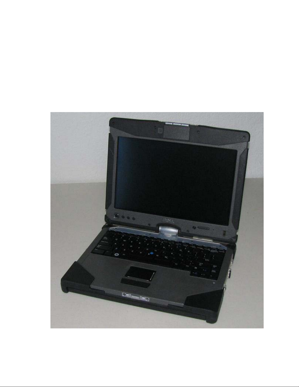
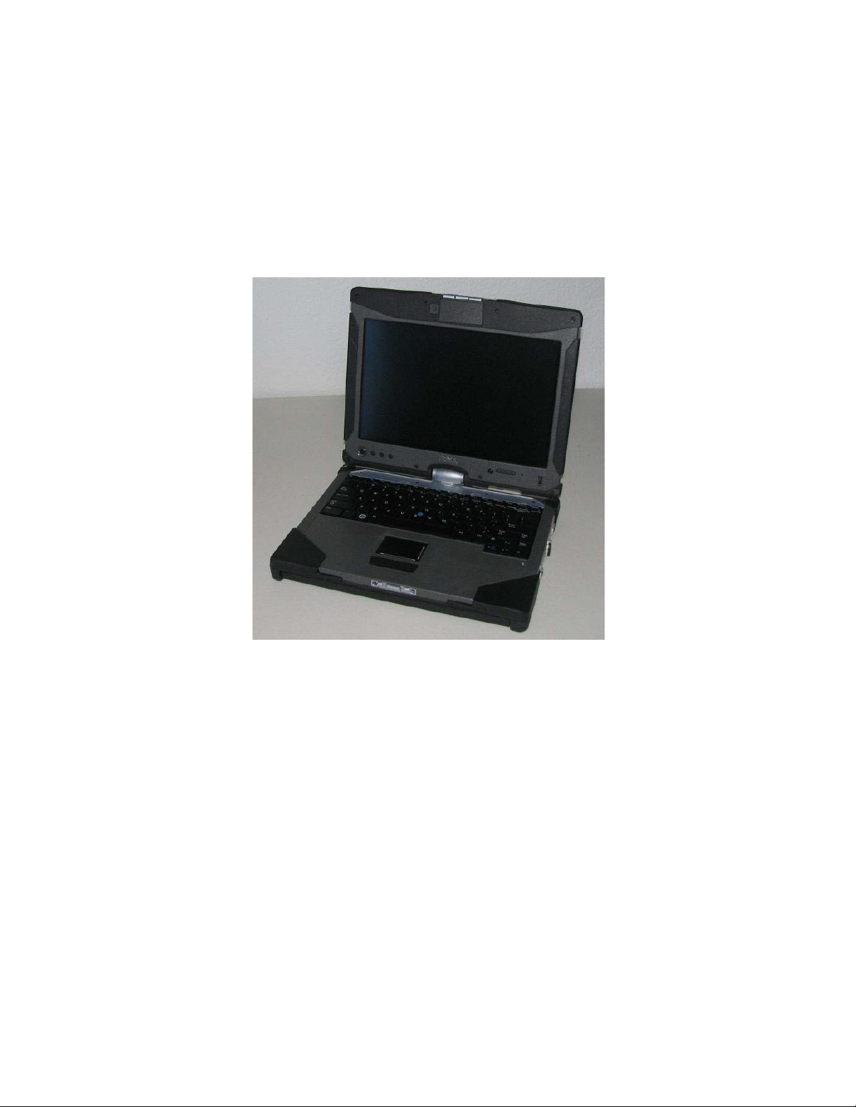
1.1.1 Notebook Mode
Your XT2 XFR can be used either in notebook mode or tablet mode. To use your XT2 XFR in notebook
mode, open the display until it reaches a comfortable viewing angle as in the image to the above, and
use the keyboard and display as you would those of any other notebook computer.
Page 6 of 94
Version A00-01
Page 7
Dell™ Latitude™ XT2 XFR Service Manual
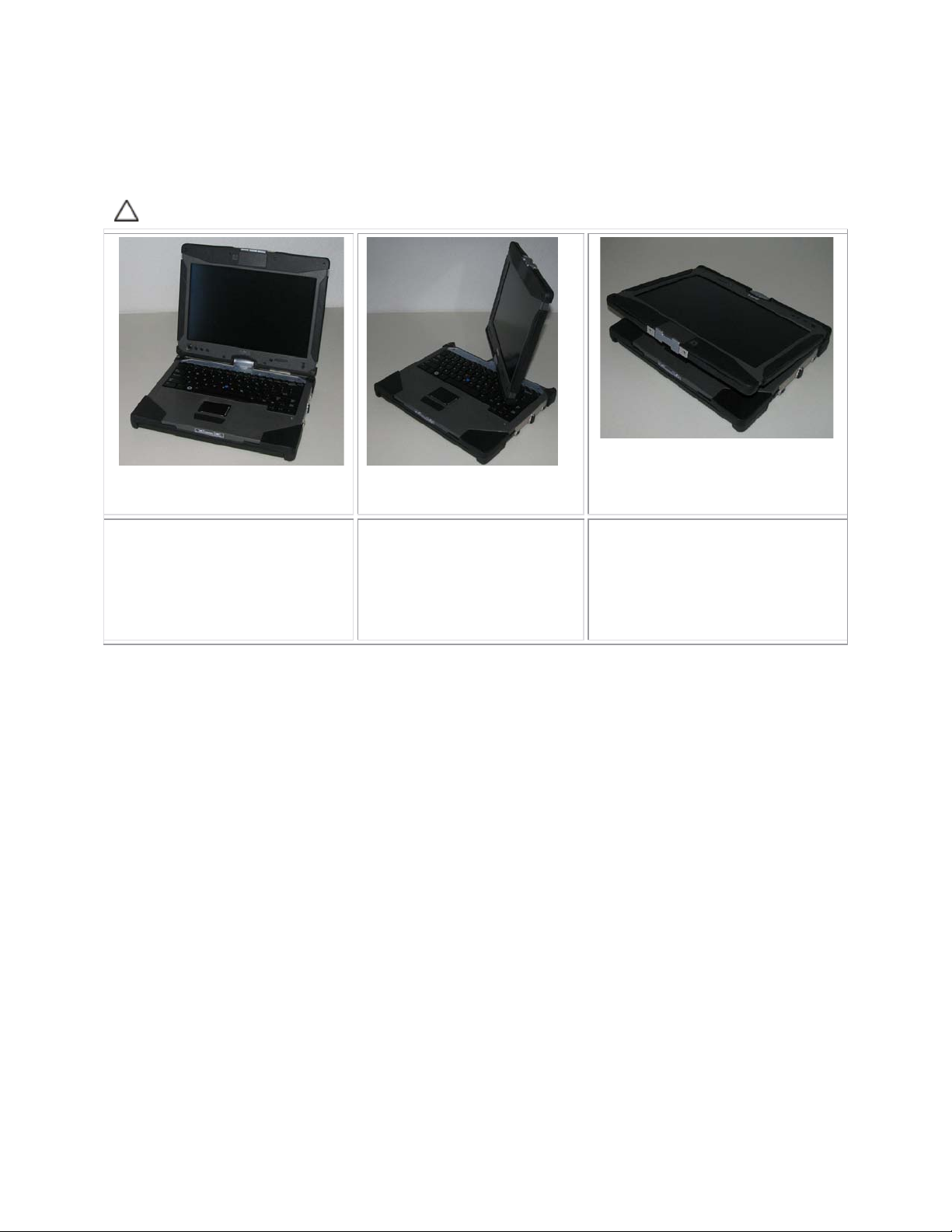
1.1.2 Tablet Mode
Your XT2 XFR converts from notebook mode to tablet mode with a 180-degree clockwise twist of the
display’s rotating hinge.
CAUTION: Forcing the hinge beyond the 180-degree point will damage the XT2 XFR.
Open the display of the XT2 XFR
until it reaches a 90-degree angle,
perpendicular to the base.
Brace the base with one hand
on the palm rest, grasp the top
of the display with the other
hand, and turn the rotating
hinge clockwise 180 degrees
until you feel the display engage
securely.
Lay the display assembly on the
base with the display facing
upwards. Press the latch down to
secure the display.
When you convert your XT2 XFR between notebook and tablet modes, the screen orientation of your
XT2 XFR will automatically change according to the settings you have established in the Dell Control
Point System Manager application or the Windows Vista Pen and Tablet settings application, most
commonly from landscape (notebook mode) to portrait (tablet mode).
Page 7 of 94 Version A00-01
Page 8
Dell™ Latitude™ XT2 XFR Service Manual
Screen rotate
button
security button
Point button
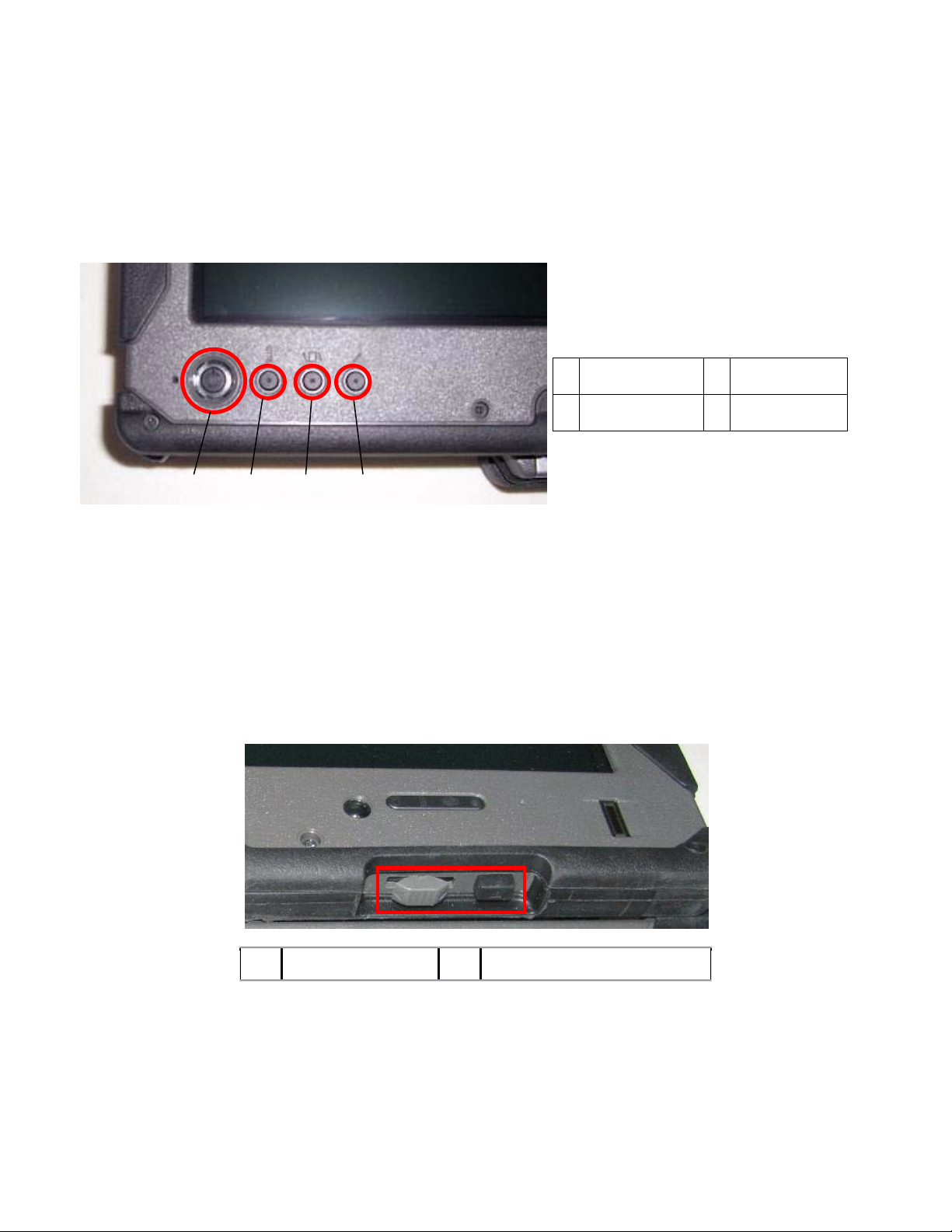
1.2 XT2 XFR Buttons
1.2.1 Tablet Buttons
Your XT2 XFR has three tablet buttons located beside the power button. In order for these buttons to
function properly,
Dell Control Point System Manager must be installed.
1 Power Button 3
2
1 2 3 4
Power button — Used to power the system on and off.
Windows Security button — If you use your XT2 XFR in tablet mode, press this button to access the
Windows Task Manager dialog box or a login screen, the same way you use the <Ctrl><Alt><Del>
key sequence in notebook mode.
Screen rotate button — While the XT2 XFR is in tablet mode, use the screen rotate button to change
the display orientation from portrait to landscape mode. Each time you press and release the screen
rotate button, the screen image rotates clockwise 90 degrees.
Dell Control Point tablet settings button — Press this button to view and configure options for the
XT2 XFR and the pen through Dell Control Point System Manager. You can configure this button to
perform a different action using Windows Vista™ XT2 XFR Settings.
Windows
Dell Control
4
1.2.2 Scroll Buttons
1 2
1 Scroll control 2 Back button
1.2.2.1 Using the Scroll Control
To scroll through a list of items or a set of pages one at a time, shift the scroll control up or down and
release. The control automatically returns to the center/neutral position when released.
To rapidly scroll through a list of items or a set of pages, shift the control up or down and hold it,
releasing it when you wish to stop scrolling.
Page 8 of 94
Version A00-01
Page 9
Dell™ Latitude™ XT2 XFR Service Manual
To select objects, press and release the scroll control when it is in the center/neutral position.
To launch context sensitive menus, press and hold the scroll control until a complete circle is drawn on
the display then release. This is equivalent to clicking the right mouse button on a notebook computer.
Use the back button to move backwards in applications that support navigation, such as web browsers
and Windows Explorer. It is also used to close the active window.
To move backward, press and release the back button.
To close the active window, press and hold the back button.
To customize the back button behavior, use the Tablet and Pen Settings in Windows Vista.
1.3 XT2 XFR Interface
1.3.1 Windows Vista/XP XT2 XFR Interface Comparison
Depending on the configuration you ordered, your XT2 XFR shipped with either the Windows Vista or
Windows XP operating system. There are several differences in the Tablet PC-interfaces between the
two. Listed below are the primary differences.
Tablet PC Interface Comparison Table
Feature Description Vista XP
Touch Ability to use finger as an input device. YES YES
Windows
Journal
Snipping
Tool
Flicks Gesture activated shortcuts for common tasks. YES NO
Check
Boxes
Cursor
Feedback
Tablet
Input
Panel
Native note-taking application which takes input directly from pen or touch.
Tool used to capture portions of visual data (documents, pictures, etc.) via
pen or touch.
Visual identifier in folders for selecting files.
Visual indicator for tap location.
Tool used to input data via pen or touch that takes the place of a keyboard.
*Available as a separate download from Microsoft.
YES YES
YES YES*
YES NO
YES NO
YES YES
Input
device-
sensitive
tools
Tablet
Cursor
Touch
Widget
Cursor
Feedback
Cursor
Feedback
Tablet Input Panel and icon change size according to pen or touch being
used.
Special Tablet cursor used for Tablet PC functions as opposed to a standard
mouse pointer.
Separate tool that appears in Touch Mode used for right-clicking purposes.
Ability to see if the target has been hit by using visual feedback for success. YES NO
Ability to see if the target has been hit by using visual feedback for success. YES NO
YES NO
YES NO
YES NO
1.3.2 Windows Vista
1.3.2.1 Pen Usage
Using the Pen as a Mouse
You can use the pen the same way you use a mouse or touch pad with a notebook computer. Holding
the pen near the display makes a small cursor appear. Moving the pen moves the cursor.
Page 9 of 94
Version A00-01
Page 10

Dell™ Latitude™ XT2 XFR Service Manual
The table below describes how to use the pen.
Electrostatic Pen Usage
Appearance Action Function
Gently tap the pen tip on the screen of your Tablet PC.
Gently tap the pen tip twice in quick succession on the
screen of your XT2 XFR.
Touch the pen on the screen and hold it in place
momentarily until Windows draws a complete circle
around the cursor.
Same as a single-click on a
mouse.
Same as a double-click on a
mouse.
Same as a right-click on a
mouse.
Working With Files
You can open, delete, or move many files or folders at
one time by selecting multiple items from a list. Using
a tablet pen, hover over one item at a time and select
the check box that appears to the left of each item.
To turn check boxes on:
1. Go to Folder Options.
2. Click on the View tab.
3. Under Advanced settings, select the Use
check boxes to select items check box, and
then click OK.
Using the Pen as a Pen
The Windows Vista handwriting recognition software makes it easy to enter text into your applications
with the pen. Some applications, such as Windows Journal, allow you to write with the pen directly
into the application window.
XT2 XFR Input Panel
When an application does not directly support pen input, you can use the Tablet PC Input Panel to
enter text into your application. If you tap in an editable area, the Tablet PC Input Panel
icon appears. Tapping the icon makes Input Panel slide out from the edge of the display.
You can also open the Input Panel by tapping the Input Panel tab, which is
docked at the edge of the screen when the Input Panel is hidden.
You can move the Input Panel tab by dragging it up or down along the edge of the screen. Then, when
you tap it, the Input Panel opens at the same horizontal location on the screen that the tab appears.
Page 10 of 94 Version A00-01
Page 11

Dell™ Latitude™ XT2 XFR Service Manual
were writing on a
You can use the writing pad, the character pad, or the on-screen keyboard to enter text. The writing
pad and the character pad convert your handwriting into typed text. The on-screen keyboard works
just like a standard keyboard except that you enter text by tapping keys with your tablet pen. The
following table describes the different choices for using the Input Panel.
Input Panel Icons
Icon Name Function
Writing Pad
Character Pad
On-screen
Keyboard
With the writing pad, you can write continuously as if you
lined piece of paper.
The character pad converts your handwriting to typed text, one letter,
number, or symbol at a time.
The on-screen keyboard is similar to a standard keyboard.
The writing pad and character pad have a number pad, a symbol pad, and web quick keys to help you
quickly and accurately enter these types of text. These quick keys are hidden when you start to write,
but appear after you insert or delete your writing.
Page 11 of 94
Version A00-01
Page 12

Dell™ Latitude™ XT2 XFR Service Manual
Pen Flicks
Pen flicks enable you to use the pen to
perform actions that normally require a
keyboard, such as pressing <Page Up> or
using the directional arrow keys. Pen flicks
are quick, directional gestures. You simply
quickly draw a short line in one of eight
directions. When a pen flick is recognized,
the XT2 XFR performs the action assigned.
The image below depicts the default pen
flick settings. These can be customized by
going to StartControl PanelPen and
Input Devices and clicking on the Flicks
tab.
1.3.2.2 Touch Usage
One of the key advantages of the XT2 XFR is the ability to easily switch from pen input
to touch input. When you use Touch Mode, a translucent image of a computer mouse,
called the touch pointer, floats beneath your finger. The touch pointer has left and right
mouse buttons that you can tap with your finger. You use the area beneath the buttons
to drag the touch pointer.
1.3.3 Windows XP
1.3.3.1 Pen Usage
Using the Pen as a Mouse
You can use the pen the same way you use a mouse or touch pad with a notebook computer. Holding
the pen near the display makes a small cursor appear. Moving the pen moves the cursor.
Tapping on the screen once is the same as clicking with a mouse. A double-tap constitutes
a double-click.
Right-clicking with the pen is accomplished by holding the pen tip down on the screen until
a red circle surrounds the pointer as illustrated to the right. Lifting the pen from here
opens up the corresponding submenu.
Page 12 of 94 Version A00-01
Page 13

Dell™ Latitude™ XT2 XFR Service Manual
Using the Pen as a Pen
The native handwriting recognition software makes it easy to enter text into your applications with the
pen. Some applications, such as Windows Journal, allow you to write with the pen directly into the
application window.
Tablet PC Input Panel
When an application does not directly support pen input, you can use the Tablet PC Input Panel to
enter text into your application. If you tap in an editable area, the Tablet PC Input Panel icon
appears. Tapping the icon makes Input Panel appear.
You can move the Input Panel tab by dragging it up or down along the edge of the screen. Then, when
you tap it, the Input Panel opens at the same horizontal location on the screen that the tab appears.
You can use the writing pad, the character pad, or the on-screen keyboard to enter text. The writing
pad and the character pad convert your handwriting into typed text. The on-screen keyboard works
just like a standard keyboard except that you enter text by tapping keys with your tablet pen. The
following table describes the different choices for using the Input Panel.
Input Panel Icons
Icon Name Function
Writing Pad
Character Pad
On-screen
Keyboard
The writing pad and character pad have a number pad, a symbol pad, and web quick keys to help you
quickly and accurately enter these types of text. These quick keys are hidden when you start to write,
but appear after you insert or delete your writing.
One of the key advantages of your XT2 XFR is the ability to easily switch from pen input to touch
input. Similar to how the pen works, tapping with your finger on the screen once is the same as
clicking with a mouse. A double-tap constitutes a double-click.
Right-clicking in Touch Mode is accomplished by holding your finger tip down on the screen until a red
circle surrounds the pointer. This can be difficult to see as often times user's fingers cover the pointer.
Lifting your finger from this point opens up the corresponding submenu.
Most of the settings for the tablet and pen are located in Control Panel under Tablet and Pen Settings.
These are also accessed through Dell Control Point System Manager.
With the writing pad, you can write continuously as if you were writing on a
lined piece of paper.
The character pad converts your handwriting to typed text, one letter, number,
or symbol at a time.
The on-screen keyboard is similar to a standard keyboard.
Touch Usage
Tablet and Pen Settings
1.4 XT2 XFR Settings
1.4.1 Installation
The N-trig Tablet Settings applet is built into the driver package. You can either install it directly from
the ResourceCD or obtain the latest version from support.dell.com. Once the file has been extracted,
Page 13 of 94 Version A00-01
Page 14

Dell™ Latitude™ XT2 XFR Service Manual
an InstallShield Wizard will walk you through the process of installing the software. The appearance of
the N-trig icon is an indication of a successful installation.
1.4.2 Windows™ XP vs. Windows Vista™
There is only one major difference in the N-trig applet between XP and Vista. On the Digitizer Options
tab, under the Input Mode section, there is no listing for Dual Mode on the XP version. Windows XP
does allow use of both pen and touch but the seamless switching capability that Vista offers is not
available.
1.4.3 N-trig Applet
The N-trig Tablet Settings applet is used to adjust several settings for the digitizer. Once the N-trig
drivers are loaded, an icon appears in the system tray.
Hovering over the icon with your pointer displays the firmware version number. Right-clicking the icon
brings up the sub menu below.
Page 14 of 94 Version A00-01
Page 15

Dell™ Latitude™ XT2 XFR Service Manual
Clicking on Properties opens up the N-trig Tablet Settings window.
There are four tabs on the N-trig Tablet Settings window:
Digitizer Options
•
Interaction Options
•
Multi-Touch Gestures
•
About
•
1.4.3.1 Digitizer Options Tab
The Digitizer Options tab is used for the following:
• Input mode selection
• Touch tuning
• Launching diagnostics
• Restoring default settings
Page 15 of 94
Version A00-01
Page 16

Dell™ Latitude™ XT2 XFR Service Manual
1.4.3.1.1 Input Mode Selection
The N-trig applet has 4 operating modes:
Pen Only — In this mode, the stylus is the only device that can be used as the input device with the
N-trig digitizer. Changing from Pen Only mode to any other mode is done by clicking with an active
input device on the N-trig Applet icon in the system tray. When the applet is open, select desired
mode and press OK.
Touch Only — In Touch Only mode, a single finger is the only input device that can be used with the
N-trig digitizer. Using the stylus is not possible. It is important to note that only a single hand contact
is allowed with the digitizer for proper execution. Changing Touch Only mode into any other mode is
done by tapping the N-trig Applet icon in System Tray using a finger or other active input device and
choosing the desired mode. Press OK to confirm.
Auto Mode — The N-Trig digitizer is capable of detecting a stylus as well as finger touch. The purpose
of Auto Mode is to allow the user intuitive toggling between the Pen Only or Touch Only modes. The
default input device for Auto Mode is the stylus as long as it is in range of the tablet screen (hovering
in proximity or in contact). A basic principle in Auto Mode is that stylus detection in the digitizer
proximity would turn the digitizer into Pen Only mode as an overriding priority. A double-tap finger
gesture on the screen (similar in style to a mouse double-click) will switch the digitizer from Pen Only
mode to Touch Only mode. The system will remain in Touch Only mode as long as the stylus is out of
range. Once the stylus is detected in range the system will automatically switch to Pen Only mode.
Dual Mode (Vista Only) — Dual Mode is a unique operational mode that is functional only while
using the Microsoft Vista operating system. In this mode, the OS switches automatically between the
available pointing device according to its internal priority and attributes.
1.4.3.1.2 Touch Tuning
If you believe that the XT2 XFR's finger detection
function is not working properly, a recalibration of the
touch feature may be in order. To accomplish this,
click the Reset button and then follow the on-screen
prompts.
CAUTION: Do NOT touch the screen while
touch reset is in progress.
A message indicating success or failure appears once
the reset routine completes. If the result is failure, try
running the diagnostics.
1.4.3.1.3 Launching Diagnostics
Running the diagnostics will help determine the functionality of the digitizer. Start by clicking the
Troubleshoot button. Pressing the Self Test button on the subsequent pop-up window starts the
diagnostics.
Page 16 of 94
Version A00-01
Page 17

Dell™ Latitude™ XT2 XFR Service Manual
After the test is complete, the results are displayed as illustrated below.
Use this table to define the result codes.
Digitizer Self Test Result Codes
Code
7
11 Stylus excitation No pen excitation
Test Error Details Symptoms
A-trigs
connectivity
Digitizer analog
processor fail
Digitizer is unable to initialize or read samples from analog
processor. No pen or touch position is reported.
Signals received during the stylus excitation test are below
certain limit. Pen may be not functional or detected in tip
only.
Sensor Antenna
14
disconnects
Sensor Antenna
15
shorts
Channel
18
imbalance
Capacitor
19
calibration
Internal Firmware
47
Error
Critical
48
Malfunction
Page 17 of 94
Digitizer grid
disconnect
Digitizer grid
shortcut
Digitizer channel
degraded
Digitizer
calibration
degraded
Internal
Firmware Error
Device Error Critical malfunction was detected, test cannot continue.
There are disconnected lines. Pen or touch may be
malfunctioning in a specific physical display area.
There are shorted lines. Pen or touch may be malfunctioning
in a specific physical display area.
There is an unbalanced channel. Pen or touch may be
malfunctioning in a specific physical display area.
The calibration capacitor in a certain channel is set to
minimal or maximum value. Pen or touch may be
malfunctioning in a specific physical display area.
Firmware resource problem in executing diagnostics.
Diagnostics tool is not functional.
Version A00-01
Page 18

Dell™ Latitude™ XT2 XFR Service Manual
49
50
Host Timeout
Error
Capacitor
Calibration
Required
Host Timeout
Error
Hardware
calibration is
required
Host communication or resources problem in executing
diagnostics.
Hardware calibration is required to gain maximum
performance.
1.4.3.2 Interaction Options Tab
The Interaction Options tab controls the visual and sound effects that can modify the user
experience while operating the system's various modes.
1.4.3.2.1 Auto Mode Switching Graphical Indicator
This section enables you to select a .gif file (image) to be displayed whenever an auto mode switching
event is detected. You can select the event that will cause the graphical indicator to appear:
• Pen Touch: Pen is detected after finger usage.
• Touch Pen: Touch is detected after pen usage.
1.4.3.2.2 Sound Feedback
This section enables you to select which .wav file (sound) will be played when the finger touches the
screen. The sound can be tested using the play button. One can enable/disable this functionality using
the specified radio button.
1.4.3.3 Multi-Touch Gestures Tab
1.4.3.3.1 Gestures
Gestures are expressions made while touching the screen of your Tablet PC with two fingers. They are
interpreted as user commands to the operating system or active application software. When the
operating system recognizes a gesture, an icon confirming the gesture appears on the screen. This
multi-touch update includes three gestures: a scroll gesture, a zoom gesture, and a two-finger doubletap gesture. Gesture features and descriptive icons shown herein are sourced by N-trig.
Page 18 of 94
Version A00-01
Page 19

Dell™ Latitude™ XT2 XFR Service Manual
Scroll Gesture
Placing two fingers on the screen and moving them horizontally or vertically generates
scrolling in the direction of movement: right, left, up, or down.
Zoom Gesture
Touching the screen with two fingers and moving them together or
apart generates a zoom-in or zoom-out command to the screen.
Two-Fingers Double-Tap Gesture
Tapping the screen twice with two fingers sends an operating system command that
you can configure. It can be used to perform actions, such as turning the display off
and disabling touch gestures (default), or run an executable program, such as one
that opens Internet Explorer.
Sensitivity Setup
To adjust the sensitivity for the two-finger gestures, double-click the N-trig icon ( ) in the system
tray, and tap the Multi-Touch Gestures tab. Set the sliders for each gesture as desired.
1.4.3.4 About Tab
The About tab is used to find information such as the driver version and firmware revision numbers.
The firmware revision number can also be obtained by hovering your pointer over the N-trig Tablet
Settings icon in the system tray.
Page 19 of 94
Version A00-01
Page 20

Dell™ Latitude™ XT2 XFR Service Manual
1.5 XT2 XFR Pen
Your XT2 XFR uses a specifically designed electrostatic pen or stylus for use in tablet PC mode.
Instead of relying on battery power, the energy source for the stylus is magnetic energy produced by
the excitation coil built into the digitizer itself. The signal from the coil is picked up by the stylus and
triggers the stylus to transmit an electric field.
The transmitted electric field is sensed by a matrix of conductive lines, accurate stylus position
determined using the low amplitude signals received on the vertical and horizontal conductors, and an
appropriate signal is transferred to the digitizer's on-board processor.
Tips come in one color type, black. The black tips present a "harder" writing feel. The system ships
with a total of two black tips. These tips are easily replaced by using the pen-tip removal tool which
looks similar to an oversized pair of tweezers. This tool also ships with the XT2 XFR.
NOTE: In the event of a suspected digitizer failure, the pen tip should be examined. If the tip is
damaged it needs to be replaced. This will oftentimes remedy the problem with the digitizer.
1.5.1 Calibrating the Pen
The pen can function at the default calibration or at a calibration set by you or by another user. It is
recommended that you use the pen only while it is calibrated to your personal calibration settings.
Calibration optimizes pen performance for each user.
To calibrate the pen:
Page 20 of 94 Version A00-01
Page 21

Dell™ Latitude™ XT2 XFR Service Manual
1. Open Dell Control Point.
2. Click System Tablet Settings.
3. On the Dell Tablet Settings window, click Pen & Input then click Calibrate.
4. Follow the instructions on the screen. The calibration markers are displayed on the screen as
plus signs (+). Tap the pen in the exact center of each of the calibration markers.
NOTE: Be sure to calibrate the pen for use in both portrait and landscape display orientations.
1.5.2 Troubleshooting
The pen is the first component to be investigated in the event of a suspected problem with the
digitizer. Verify the tip is in good shape (free of chips, excessive wear, etc.) by closely examining it. If
there is any doubt, you should change out the tip with a new one or one that is known to be in good
condition.
You should also verify that the touch capabilities are not affected. Switch to touch mode and see if the
problem still exists. If there are no symptoms present while in touch mode, the pen tip is the most
likely suspect. If the problem does persist in touch mode you should run diagnostics and take the
necessary steps depending on the results.
Page 21 of 94
Version A00-01
Page 22

Dell™ Latitude™ XT2 XFR Service Manual
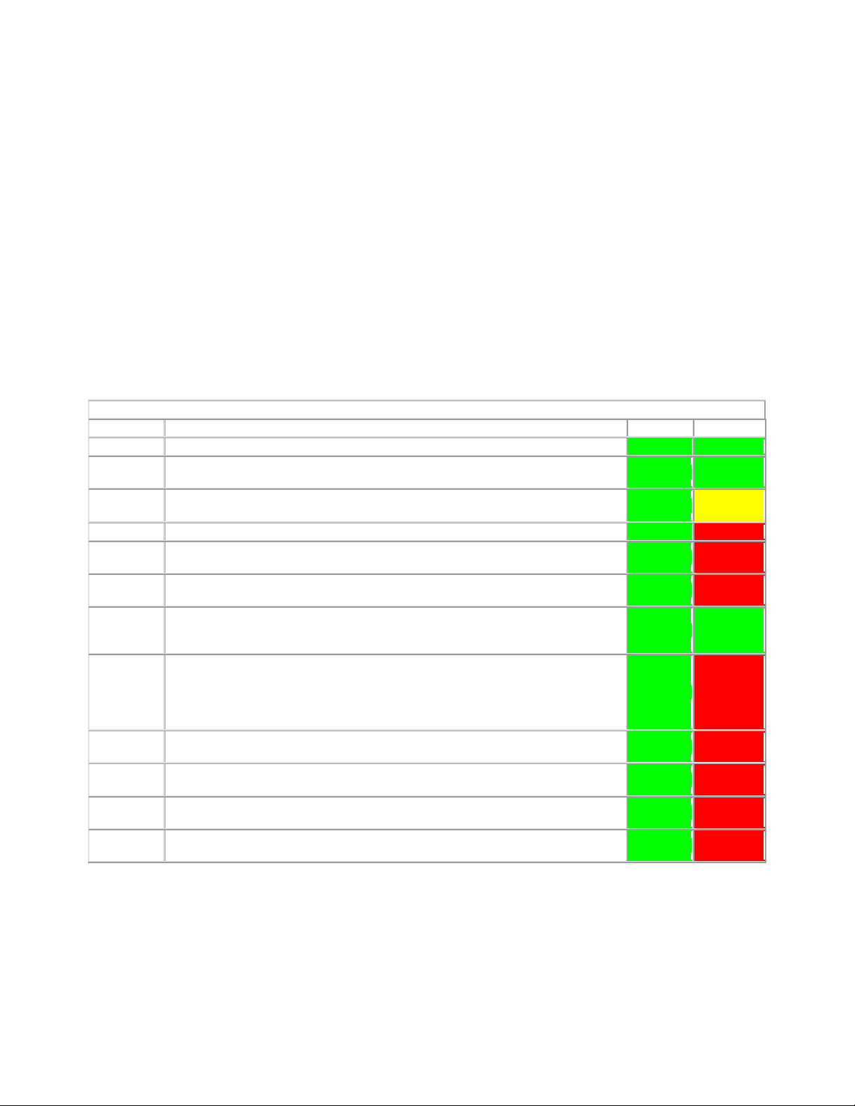
1.6 Application Matrix
The following matrix shows the gestures supported by the operating system and specific application
software packages. Other applications may also respond to these gestures.
Operating System Microsoft™ Windows Vista™ Microsoft Windows™ XP
Application
Family
Windows
Windows
Live
Virtual Earth
Microsoft
Office 2007
Microsoft
Office 2003
Application
Name
Explorer Yes Yes Yes No Yes Yes
Photo
Gallery
Photo
Gallery
No No No No No No
Outlook® Yes Yes No Yes Yes No
Word Yes Yes Yes Yes Yes No
Excel® Yes Yes Yes Yes Yes No
Power
Point®
One Note® Yes Yes Yes Yes Yes No
Picture
Manager
Outlook® Yes Yes Yes Yes Yes Yes
Word Yes Yes Yes Yes Yes Yes
Excel
®
Power
Point®
One Note® Yes Yes Yes Yes Yes Yes
Picture
Manager
Pinch/Zoom
Yes Yes Yes No No No
Yes Yes Yes No No No
Yes Yes Yes Yes Yes Yes
Yes Yes Yes Yes Yes Yes
Yes Yes Yes Yes Yes Yes
Yes Yes Yes Yes Yes Yes
Yes Yes Yes Yes Yes Yes
Horizontal
Scroll
Vertical
Scroll
Pinch/Zoom
Horizontal
Scroll
Vertical
Scroll
2 Working on Your XT2 XFR
Page 22 of 94
Version A00-01
Page 23

Dell™ Latitude™ XT2 XFR Service Manual
2.1 Before Working Inside Your XT2 XFR
Use the following safety guidelines to help protect your XT2 XFR from potential damage and to help to
ensure your personal safety. Unless otherwise noted, each procedure included in this document
assumes that the following conditions exist:
• You have performed the steps in
• You have read the safety information that shipped with your XT2 XFR.
• A component can be replaced or--if purchased separately--installed by performing the removal
procedure in reverse order.
WARNING: Before working inside your XT2 XFR, read the safety information that
shipped with your XT2 XFR. For additional safety best practices information, see the
Regulatory Compliance Homepage at www.dell.com/regulatory_compliance.
CAUTION: Only a certified service technician should perform repairs on your XT2 XFR.
Damage due to servicing that is not authorized by Dell is not covered by your
warranty.
CAUTION: To avoid electrostatic discharge, ground yourself by using a wrist grounding
strap or by periodically touching an unpainted metal surface, such as a connector on
the back of the computer.
Working on Your XT2 XFR.
CAUTION: Handle components and cards with care. Do not touch the components or
contacts on a card. Hold a card by its edges or by its metal mounting bracket. Hold a
component such as a processor by its edges, not by its pins.
CAUTION: When you disconnect a cable, pull on its connector or on its pull-tab, not on
the cable itself. Some cables have connectors with locking tabs; if you are
disconnecting this type of cable, press in on the locking tabs before you disconnect the
cable. As you pull connectors apart, keep them evenly aligned to avoid bending any
connector pins. Also, before you connect a cable, ensure that both connectors are
correctly oriented and aligned.
NOTE: The color of your XT2 XFR and certain components may appear differently than shown in
this document.
To avoid damaging your XT2 XFR, perform the following steps before you begin working inside the XT2
XFR.
1. Ensure that your work surface is flat and clean to prevent the XT2 XFR cover from being
scratched.
2. Turn off your XT2 XFR (see
3. If the XT2 XFR is connected to a docking device (docked) such as the optional Media Base or
Battery Slice, undock it.
CAUTION: To disconnect a network cable, first unplug the cable from your XT2 XFR and
then unplug the cable from the network device.
4. Disconnect all network cables from the XT2 XFR.
5. Disconnect your XT2 XFR and all attached devices from their electrical outlets.
6. Close the display and turn the XT2 XFR upside-down on a flat work surface.
CAUTION: To avoid damaging the system board, you must remove the main battery
before you service the XT2 XFR.
7. Remove the main battery (see
8. Turn the XT2 XFR top-side up.
9. Open the display.
10. Press the power button to ground the system board.
Turning Off Your XT2 XFR).
Removing the Main Battery).
Page 23 of 94
Version A00-01
Page 24

Dell™ Latitude™ XT2 XFR Service Manual
CAUTION: To guard against electrical shock, always unplug your XT2 XFR from the
electrical outlet before opening the display.
CAUTION: Before touching anything inside your XT2 XFR, ground yourself by touching
an unpainted metal surface, such as the metal at the back of the XT2 XFR. While you
work, periodically touch an unpainted metal surface to dissipate static electricity,
which could harm internal components.
11. Remove any installed ExpressCards or Smart Cards from the appropriate slots.
12. Remove the hard drive (see
Removing the Hard Drive).
2.2 Recommended Tools
The procedures in this document may require the following tools:
• Small flat-blade screwdriver
• #0 Phillips screwdriver
• #1 Phillips screwdriver
• Small plastic scribe
• Flash BIOS update program CD
2.3 Turning Off Your XT2 XFR
CAUTION: To avoid losing data, save and close all open files and exit all open programs
before you turn off your XT2 XFR.
1. Shut down the operating system:
• In Windows Vista:
Click Start , then click the arrow in the lower-right corner of the Start menu as shown
below, and then click Shut Down.
• In Windows XP:
Click Start Turn Off Computer Turn Off.
The XT2 XFR turns off after the operating system shutdown process is complete.
2. Ensure that the XT2 XFR and all attached devices are turned off. If your XT2 XFR and attached
devices did not automatically turn off when you shut down your operating system, press and
hold the power button for about 4 seconds to turn them off.
2.4 After Working Inside Your XT2 XFR
Page 24 of 94
Version A00-01
Page 25

Dell™ Latitude™ XT2 XFR Service Manual
After you complete any replacement procedure, ensure you connect any external devices, cards, and
cables before turning on your computer.
CAUTION: To avoid damage to the XT2 XFR, use only the battery designed for this
particular Dell computer. Do not use batteries designed for other Dell computers.
1. Connect any external devices, such as a port replicator, battery slice, or media base, and
replace any cards, such as an ExpressCard.
2. Connect any telephone or network cables to your XT2 XFR.
CAUTION: To connect a network cable, first plug the cable into the network device and
then plug it into the computer.
3. Replace the
main battery.
4. Connect your XT2 XFR and all attached devices to their electrical outlets.
5. Turn on your XT2 XFR.
3 Screw Chart
Chassis
Location
1
USB/1394 DOOR
hinge assy screw-M3 x 3 21106-03 2
Latch screw-M1.2 40621 1
door to chassis mouting screw 21106-00 4
2
IO/AUDIO DOOR
3 IO/VGA DOOR
4 POWER DOOR
5 RF PASS THRU
M2 x 3 21106-00 2
6 STYLUS BAY
Self tapping screw 40426 1
7 SNIFFER ASSEMBLY
M2 x 3 21106-00 2
8 SYSTEM BOARD
M2.5 x 5 21106-01 1
M2.5 x 8 21106-02 1
hinge assy screw-M3 x 3 21106-03 3
door to chassis mouting screw 21106-00 6
hinge assy screw-M3 x 3 21106-03 2
door to chassis mouting screw 21106-00 4
hinge assy screw-M3 x 3 21106-03 1
door to chassis mouting screw 21106-00 2
Screw
Latch screw-M1.2 40621 1
Latch screw-M1.2 40621 1
Latch screw-M1.2 40621 1
Part # Qty
Page 25 of 94
Version A00-01
Page 26

Dell™ Latitude™ XT2 XFR Service Manual
9 WIFI ASSEMBLY
custom 1
10 HINGE PLATE TO CHASSIS
Palm Rest
1 KEYBOARD DOOR
M2 x 3 21106-00 2
2
TOUCH PAD ASSEMBLY
3
USB HUB BOARD
BLUETOOTH MODULE
4
(option)
5
KEYBOARD
6
Upper Palm Rest Screw
LCD inner- Bezel
1 FPR board
LCD Outer
CSK screw-M2x 5 40628 1
M2.5 x 5 21106-01 2
M2 x 3 21106-00 4
M2 x 3 21106-00 2
M2 x 3 21106-00 1
M2 x 3 21106-00 2
M2 x 3 21106-00 1
1 Rocker Switch Assy
custom Thread Forming 3
2 Antenna bracket
LCD ASSY
1 LCD mouting screws-PCB
custom csk 40319 3
2 Hinge Moutning screws
M2.5 x 5 21106-01 4
3 ID Plate
M2.5 x 5 21106-01 4
LCD inner and Outer Assy
4
screws
M2.5 x 8 21106-02 8
front top side M2.5 x 7 40630 4
5 Hinge Cover screw
M2.5 x 5 21106-01 1
Base to LCD
1 hinge mouting base screw
M3 x 3 40500 4
2 Cable Clamp screws
M2 x 3 21106-00 4
Page 26 of 94
Version A00-01
Page 27

Dell™ Latitude™ XT2 XFR Service Manual
custom Thread Forming
Base to Palm rest
1 under the battery area
M2.5 x 5 21106-01 7
2 under the battery area
M2.5 x 8 21106-02 1
3 bottom side screws
M2.5 x 8 21106-02 9
Battery Module
1 Battery module assy
KEYPAD / HINGE
COVER
1 Captive screw-M2
custom 40190 4
Dimms Door
1 Captive screw-M2
custom 40190 4
Latch Palm Rest
1 shoulder screw, Captive
custom 40301 2
M2 x 3 21106-00 4
4 Adding and Replacing Parts
4.1 Main Battery
WARNING: Before working inside your XT2 XFR, read the safety information that
shipped with your XT2 XFR. For additional safety best practices information, see the
Regulatory Compliance Homepage at
www.dell.com/regulatory_compliance.
Page 27 of 94
Version A00-01
 Loading...