

Page 1
Dell XC6320 Web-Scale
Hyperconverged Appliance
Getting
With Your
Started
System
Scan to see how-to videos, documentation, and
troubleshooting information.
Page 2
Notes, Cautions, and Warnings
Copyright © 2016 Dell Inc. All rights reserved. This product is protected by U.S. and international
copyright and intellectual property laws. Dell™ and the Dell logo are trademarks of Dell Inc. in the
United States and/or other jurisdictions. All other marks and names mentioned herein may be
trademarks of their respective companies.
Printed in Malaysia.
Regulatory Model: B08S Regulatory Type: B08S003
2016-03 P/N G40F3 Rev. A01
NOTE: A NOTE indicates important information that helps you make better
use of your computer.
CAUTION: A CAUTION indicates potential damage to hardware or
loss of data if instructions are not followed.
WARNING: A WARNING indicates a potential for property damage,
personal injury, or death.
Page 3
Getting Started With Your System
|
3
CAUTION: Restricted Access Location
This system is intended for installation only in restricted access locations as defined in
Cl. 1.2.7.3 of IEC 60950-1: 2001 where both these conditions apply:
•
Access can only be gained by service persons or by users who have been
instructed about the reasons for the restrictions applied to the location and about
any precautions that shall be taken.
•
Access is through the use of a tool or lock and key, or other means of security,
and is controlled by the authority responsible for the location.
Installation and Configuration
WARNING: Before performing the following procedure, review and follow
the safety instructions that came with the system.
Installing the Tool-less Rail Solution
WARNING: Whenever you need to lift the system, get others to assist
you. To avoid injury, do not attempt to lift the system by yourself.
WARNING: The system is not fixed to the rack or mounted on the
rails. To avoid personal injury or damage to the system, you must
adequately support the system during installation and removal.
WARNING: To avoid a potential electrical shock hazard, a third wire
safety grounding conductor is necessary for the rack installation.
The rack equipment must provide sufficient airflow to the system to
maintain proper cooling.
CAUTION: When installing rails in a square-hole rack it is important
to ensure that the square peg slides through the square holes.
Page 4
4
|
Getting Started With Your System
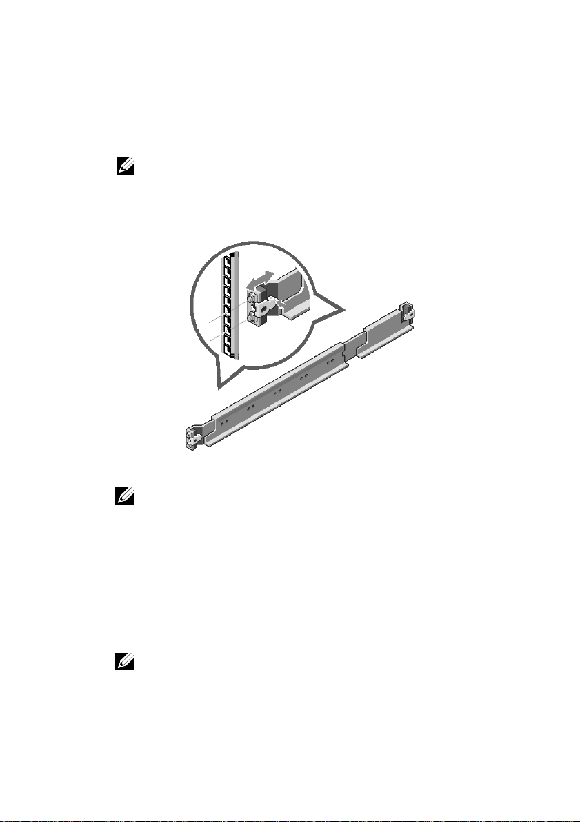
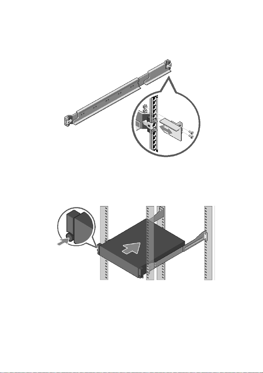
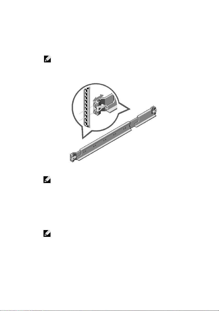
1 Push the latch release buttons on the midpoints of the end piece to open the
rail latches (see Figure 1).
2 Align the end pieces of the rails on the vertical rack flanges to seat the pegs
in the bottom hole of the first U and the top hole of the second U.
NOTE: The rails can be used in both square-hole and round-hole
racks (see Figure 1).
Figure 1. Pushing the Latch Release Buttons
3 Engage the end of the rails and release the latch release button to have the
4 On each vertical rack flange on the back, put two screw bases into the two
5 Install the chassis stabilizer shipping brackets (optional) on the back rack
6 Install and tighten the screws.
NOTE: To remove the rails, push the latch release button on the
midpoints of the end piece and unseat each rail.
latches locked in place.
square holes right above the rail (see Figure 2).
flanges.
NOTE: To transport systems already installed in the rack, ensure
that the two chassis stabilizer shipping brackets (optional) are in
place.
Page 5
Getting Started With Your System
|
5
Figure 2. Installing the Chassis Stabilizer Shipping Brackets
7 Slide the system into the rack (see Figure 3).
8 Tighten the thumbscrews to secure the ears of the system to the front of the
rack flanges.
Figure 3. Installing the Chassis into the Rack
Page 6
6 | Getting Started With Your System
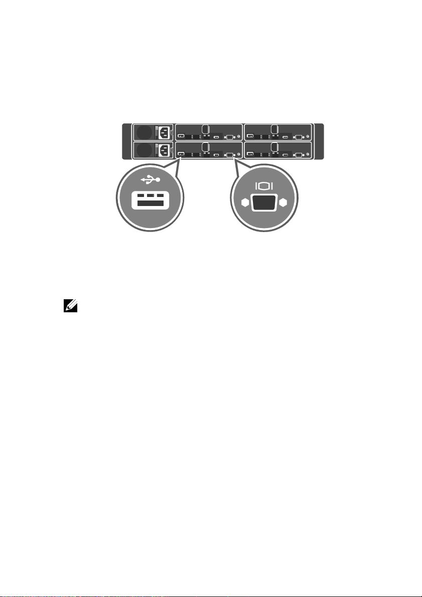
Connecting the Keyboard, Mouse, and Monitor (Optional)
Figure 4. Optional—Connecting the Keyboard, Mouse and Monitor
Connect the keyboard, mouse, and monitor (optional).
The connectors on the back of your system have icons indicating which cable to plug
into each connector. Ensure that you tighten the screws (if any) on the monitor’s cable
connector.
NOTE: The system supports only one USB port and a micro USB port. If
you require more than one USB outlet at a time, use USB hub or an
adapter cable.
Page 7
Getting Started With Your System
|
7
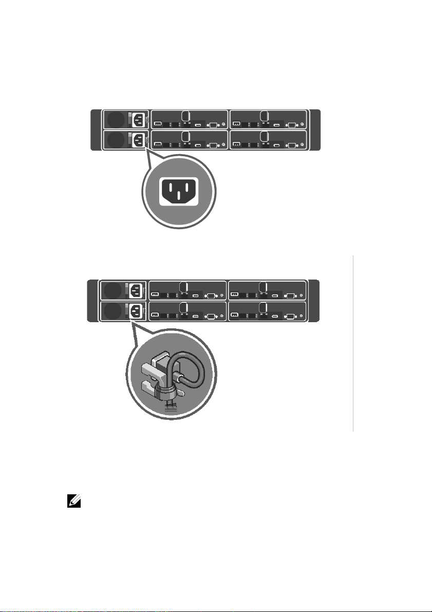
Connecting the Power Cable(s)
Figure 5. Connecting the Power cable
Figure 6. Routing the cables
Connect the system’s power cable(s) to the system and, if a monitor is used, connect the
monitor’s power cable to the monitor. Plug the other end of the power cable(s) into a
grounded electrical outlet or a separate power source such as an uninterrupted power
supply (UPS) or a power distribution unit.
NOTE: The system supports both AC and HVDC power inputs. Your
system can support up to two 1600 W power supply units (PSUs)
(200−240 VAC nominal input voltage).
Page 8
8 | Getting Started With Your System
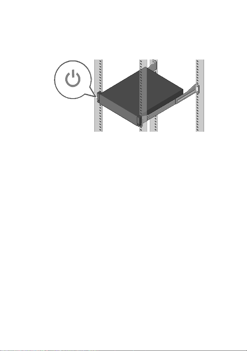
Turning on the System
Figure 7. Pressing the Power Button in Front of the System
Press the power button(s) either in front or back of the system. The power indicators
glow in green color.
Page 9

Installing Operating System
To install an operating system for the first time, see the installation and
configuration documentation for your operating system. Ensure that the
operating system is installed before installing hardware or software not
purchased with the system. For more information about the Dell XC6320
system, refer to the Dell XC6320 Owner’s Manual available at
Dell.com/xcseriesmanuals.
NOTE: For more information about supported operating systems, see
Dell.com/ossupport.
Page 10

Page 11
Dell XC6320 Web
级超聚合设备
系统使用入门
扫描以查看教学视频、
文档和故障排除信息。
Page 12
注、小心和警告
版权所有 © 2016 Dell Inc. 保留所有权利。本产品受美国及国际版权法和知识产权法保护。Dell™ 和 Dell 徽标是
Dell Inc. 在美国和/或其他管辖区域的商标。此处提到的所有其他商标和名称可能是其各自所属公司的商标。
马来西亚印刷。
管制型号:B08S 管制类型:B08S003
2016 年 3 月 P/N G40F3 Rev. A01
注:“注”表示可以帮助您更好地使用计算机的重要信息。
小心:“小心”表示如果不遵循说明,就有可能导致硬件损坏或数据丢失。
警告:“警告”表示可能导致财产损失、人身伤害或死亡的潜在危险。
Page 13
系统使用入门
|
13
小心:进出受限区域
本系统只能安装在进出受限区域中,此区域的限定出自 Cl.1.2.7.3,
IEC 60950-1:2001,其中应符合以下两个条件:
• 只能由维护人员,或者由已知晓实施区域进出限制原因以及如何采取任何
所需预防措施的用户进入。
• 通过使用工具或锁和钥匙或者其他安全手段进入,并由负责该区域安全
的管理机构进行控制。
安装和配置
警告:在执行以下步骤之前,请仔细查阅并遵守系统随附的安全说明。
安装免工具式导轨解决方案
警告:需要提起系统时,请让其他人进行协助。为避免受伤,请勿尝试独自
提起系统。
警告:系统并未固定到机架中或安装在导轨上。为了避免人身伤害或系
统损坏,必须在安装和拆卸过程中为系统提供足够的支撑。
警告:为避免潜在的触电危险,必须在机架安装期间使用第三根安全接地
导线。机架设备必须向系统提供足够的气流,以保持正常的散热功能。
小心:当在方形孔机架中安装导轨时,务必确保方形销钉通过方形孔。
Page 14
14
|
系统使用入门
1 推端件中间点位置处的闩锁释放按钮,以打开导轨闩锁(请参见图 1)。
2 在垂直机架凸缘上对齐导轨的各端件,将销钉安装在第一 U 的底部孔
和第二 U 的顶部孔中。
注:方形孔机架和圆形孔机架中均可使用导轨(参见图 1)。
图 1. 推闩锁释放按钮
注:要卸下导轨,推端件中间点位置处的闩锁释放按钮,并取出每
根导轨。
3 使导轨端部接合,并释放闩锁释放按钮使闩锁装置锁定到位。
4 在背面的每个垂直机架凸缘上,将两个螺钉基座放置在导轨正上方的
两个方形孔内(请参见图 2)。
5 在背面机架凸缘上安装机箱稳定装运支架(可选)。
6 安装并拧紧螺钉。
注:要运输已安装在机架中的系统,确保两个机箱稳定装运支架(可选)
已就位。
Page 15

系统使用入门
|
15
图 2. 安装机箱稳定装运支架
7 将系统滑入机架(请参见图 3)。
8 拧紧指旋螺钉,将系统耳状部分固定到机架凸缘的正面。
图 3. 将机箱安装到机架中
Page 16

16
|
系统使用入门
连接键盘、鼠标和显示器(可选)
图 4. 可选 - 连接键盘、鼠标和显示器
连接键盘、鼠标和显示器(可选)。
系统背面的各连接器带有图标,以指示每个连接器中应插入的电缆。确保拧紧
显示器电缆连接器上的螺钉(如果有)。
注:系统只支持一个 USB 端口和一个 micro USB 接口。如果一次需要使用
多个 USB 插座,可使用 USB 集线器或适配器电缆。
Page 17

系统使用入门
|
17
连接电源电缆
图 5. 连接电源电缆
图 6. 电缆布线
将系统的电源电缆连接到系统。如果使用显示器,则将显示器的电源电缆连接到
显示器。将电源电缆的另一端插入接地电源插座,或插入单独的电源(如不间断
电源设备 (UPS) 或配电装置)。
注:系统支持 AC 和 HVDC 电源输入。系统最多可支持两个 1600 W 电源
装置 (PSU) (200-240 VAC 额定输入电压)。
Page 18

18
|
系统使用入门
开启系统
图 7. 按下系统正面的电源按钮
按下系统正面或背面的电源按钮。电源指示灯将亮起为绿色。
Page 19

安装操作系统
在首次安装操作系统时,参阅操作系统的安装和配置文档。确保首先安
装操作系统,然后安装未随该系统购买的硬件或软件。有关 Dell
XC6320 系统的更多信息,参阅 Dell.com/xcseriesmanuals 上提供的 Dell
XC6320 Owner’s Manual(Dell XC6320 用户手册)。
注:有关支持的操作系统的更多信息,参阅 Dell.com/ossupport。
Page 20

Page 21

Dell XC6320 Web-Scale
Hyperconverged Appliance
Memulai
Sistem Anda
Pindai untuk melihat video panduan, dokumentasi, dan
informasi pemecahan masalah.
Page 22

Catatan, Perhatian, dan Peringatan
Hak cipta © 2016 Dell Inc. Hak cipta dilindungi undang-undang. Produk ini dilindungi oleh hak cipta
AS dan internasional serta undang-undang kekayaan intelektual. Dell™ dan logo Dell merupakan
hak cipta Dell Inc. di Amerika Serikat dan/atau yurisdiksi lainnya. Semua merek dan nama lain yang
disebutkan di sini mungkin merupakan merek dagang perusahaannya masing-masing.
Dicetak di Malaysia.
Model Resmi: B08S Tipe Resmi: B08S003
2016-03 No. Komp. G40F3 Rev. A01
CATATAN: CATATAN menunjukkan informasi penting yang akan
membantu Anda untuk menggunakan komputer dengan lebih baik.
PERHATIAN: PERHATIAN menunjukkan kemungkinan terjadinya
kerusakan perangkat keras atau kehilangan data jika petunjuk
tidak dipatuhi.
PERINGATAN: PERINGATAN menunjukkan kemungkinan
terjadinya kerusakan properti, cedera pribadi, atau kematian.
Page 23

Memulai Sistem Anda
|
23
PERHATIAN: Lokasi Akses Terbatas
Sistem ini ditujukan hanya untuk pemasangan pada lokasi akses terbatas seperti
yang dijelaskan dalam Kl. 1.2.7.3 dari IEC 60950-1: 2001 di mana kedua syarat
berikut berlaku:
• Akses hanya dapat dimiliki oleh seseorang yang bertanggung jawab terhadap
atau oleh pengguna yang memiliki pengetahuan tentang alasan mengapa
pembatasan berlaku pada lokasi dan tentang tindakan pencegahan yang harus
dilakukan.
• Akses meliputi penggunaan alat atau pengunci dan kunci, atau alat
pengamanan lainnya, dan harus dikontrol oleh pihak yang berwenang pada
lokasi tersebut.
Pemasangan dan Konfigurasi
PERINGATAN: Sebelum melakukan prosedur berikut, cermati dan ikuti
petunjuk keselamatan yang disertakan bersama sistem.
Memasang Tool-less Rail Solution
PERINGATAN: Pada saat Anda akan mengangkat sistem, mintalah
orang lain untuk membantu Anda. Untuk menghindari cedera, jangan
mengangkat sistem tanpa bantuan orang lain.
PERINGATAN: Sistem tidak terpasang sempurna pada rak atau
terpasang ada rel. Untuk menghindari cedera pribadi atau
kerusakan sistem, Anda harus memiliki dukungan yang memadai
pada saat pemasangan dan pelepasan sistem.
PERINGATAN: Untuk menghindari bahaya sengatan listrik,
diperlukan konduktor grounding keselamatan kabel ketiga untuk
pemasangan rak. Peralatan rak harus memiliki aliran udara yang
mencukupi agar sistem mendapatkan pendinginan yang baik.
PERHATIAN: Ketika memasang rel pada rak dengan lubang persegi,
pastikan bahwa pasak persegi terpasang dengan sempurna pada
lubang persegi.
Page 24

24
|
Memulai Sistem Anda
1 Tekan tombol pelepas selot pada bagian tengah ujung rel untuk membuka
penguncian rel (lihat Gambar 1).
2 Sejajarkan ujung rel pada pinggiran rak vertikal untuk menyelaraskan pasak
di dalam lubang bawah pada U pertama dan lubang atas pada U kedua.
CATATAN: Rel dapat digunakan baik untuk rak dengan lubang
persegi maupun rak dengan lubang bulat (lihat Gambar 1).
Gambar 1. Menekan Tombol Pelepas Selot
CATATAN: Untuk melepaskan rel, tekan tombol pelepas selot
pada bagian tengah dari ujung rel dan lepaskan setiap rel.
3 Pasang ujung rel pada tempatnya kemudian lepaskan tombol pelepas selot
untuk mengunci selot pada tempatnya.
4 Pada setiap pinggiran rak vertikal di sisi belakang, gunakan dua sekrup pada
dua lubang persegi yang terdapat tepat di atas rel (lihat Gambar 2).
5 Pasang braket penyeimbang sasis (opsional) pada sisi belakang pinggiran rak.
6 Pasang dan kencangkan sekrup.
CATATAN: Untuk memindahkan sistem yang sudah terpasang di
dalam rak, pastikan bahwa dua braket penyeimbang sasis
(opsional) telah terpasang.
Page 25

Memulai Sistem Anda
|
25
Gambar 2. Memasang Braket Penyeimbang Sasis
7 Dorong sistem ke dalam rak (lihat Gambar 3).
8 Kencangkan sekrup baut untuk memasang telinga sistem pada bagian depan
pinggiran rak.
Gambar 3. Memasang Sasis ke Rak
Page 26

26 | Memulai Sistem Anda
Menyambungkan Keyboard, Mouse, dan Monitor (Opsional)
Gambar 4. Opsional—Menyambungkan Keyboard, Mouse, dan Monitor
Sambungkan keyboard, mouse, dan monitor (opsional).
Konektor pada sisi belakang sistem memiliki ikon yang menunjukkan kabel mana
yang harus dipasang pada setiap konektornya. Pastikan bahwa Anda sudah
mengencangkan sekrup (jika ada) dengan baik pada konektor kabel monitor.
CATATAN: Sistem hanya mendukung satu port USB dan micro USB. Jika Anda
memerlukan lebih dari satu outlet USB, gunakan hub USB atau kabel adaptor.
Page 27

Memulai Sistem Anda
|
27
Menyambungkan Kabel Daya
Gambar 5. Menyambungkan kabel Daya
Gambar 6. Merutekan kabel
Sambungkan kabel daya sistem ke sistem dan, jika Anda menggunakan monitor,
sambungkan juga kabel daya monitor ke monitor. Sambungkan ujung kabel daya yang
lain ke stopkontak yang diground atau ke sumber daya terpisah seperti UPS atau unit
distribusi daya.
CATATAN: Sistem mendukung input AC dan HVDC. Sistem Anda
dapat mendukung dua unit suplai daya (PSU) hingga 1600 W
(200−240 VAC tegangan input nominal).
Page 28

28 | Memulai Sistem Anda
Menyalakan Sistem
Gambar 7. Menekan Tombol Daya di Sisi Depan Sistem
Tekan tombol daya baik yang berada di sisi depan atau belakang sistem. Indikator daya
akan menyala hijau.
Page 29

Memasang Sistem Operasi
Untuk memasang sistem operasi untuk pertama kalinya, lihat dokumentasi
pemasangan dan konfigurasi untuk sistem operasi Anda. Pastikan bahwa
sistem operasi telah terpasang sebelum memasang perangkat keras atau
perangkat lunak yang tidak dibeli bersama sistem. Untuk informasi lebih
lanjut mengenai sistem Dell XC6320, silakan lihat Panduan Pengguna Dell
XC6320 yang tersedia di Dell.com/xcseriesmanuals.
CATATAN: Untuk informasi lebih lanjut mengenai sistem operasi yang
didukung, lihat Dell.com/ossupport.
Page 30

Page 31

Dell XC6320 ウェブスケール
ハイパーコンバージド
アプライアンス
はじめに
スキャンして、ハウツービデオ、マニュアル、および
トラブルシューティングの情報を参照してください。
Page 32

メモ、注意、警告
著作権 © 2016 Dell Inc. 無断転載を禁じます。この製品は、米国ならびに国際的な著作権法および 知的財産法によって保
護されています。Dell™ および Dell のロゴは米国および / またはその他管轄区域における Dell Inc. の商標です。本書で
使用されているその他すべての商標および名称は、各社の商標である場合がありま す。
Printed in Malaysia.
規制適合モデル:B08S 規制適合タイプ:B08S003
2016-03 P/N G40F3 Rev. A01
メモ:お使いのコンピュータをより良く使用するために役に立つ重要情報を示します。
注意:手順に従わない場合、ハードウェアの損傷やデータの損失が発生する可
能性があることを示します。
警告:物的損害、けが、または死亡の原因となる可能性があることを示しています。
Page 33

はじめに
|
33
注意:立入制限区域
このシステムは、IEC 60950-1: 2001 の Cl.1.2.7.3 で定義されているように、次の両方の
状況が適用される、アクセス制限区域への取り付けのみを対象としています。
• この区域への立ち入りは、その場所に適用された制限の理由、および講じる必要
のある予防措置についての指導を受けた保守担当者またはユーザーのみに限定さ
れます。
• この区域への立ち入りは、道具もしくは施錠、またはその他のセキュリティ手段
を使用して行われ、当区域に対する責任を負う主管者によって制御されます。
設置および設定
警告:次の手順を実行する前に、システムに付属の安全上の注意をよく読んで指示
に従ってください。
ツールレスレールソリューションの取り付け
警告:システムを持ち上げる必要がある場合は、必ず誰かの手を借りてください。
けがを防ぐため、システムを一人で持ち上げようとしないでください。
警告:システムはラックに固定されておらず、レールに取り付けられてもいませ
ん。人身傷害やシステムの損傷を避けるため、取り付けと取り外しの際にはシス
テムを十分に支えてください。
警告:感電の危険を避けるため、ラックの取り付けには第 3 種安全用接地線が必
要です。適切な通気による冷却効果を維持するために、ラック装置からシステムに
十分な空気の流れが必要です。
注意:角穴ラックにレールを取り付ける時は、角型ペグを角穴に確実に挿入する
ことが重要です。
Page 34

34
|
はじめに
1 末端部の中間点にあるラッチリリースボタンを押してレールラッチを開きます
(図 1 を参照)。
2 レールのエンドピースを垂直ラックフランジに合わせ、ペグを 1 番目の U の
最下部の穴と 2 番目の U の最上部の穴に装着します。
メモ:レールは角型穴と丸型穴の両方のラックに使用できます(図 1 を参照)。
図 1.ラッチリリースボタンを押す
メモ:レールを取り外すには、末端部の中間点にあるラッチリリースボタンを押して、
各レールを外します。
3 レールの末端をはめ込み、ラッチリリースボタンを離してラッチを所定の場
所にロックします。
4 背面の各垂直ラックフランジで、2 個のねじ込口金をレールのすぐ上にある
2 つの角穴に差し込みます(図 2 を参照)。
5 背面ラックフランジにシャーシスタビライザシッピングブラケット(オプシ
ョン)を取り付けます。
6 ネジを取り付けて締めます。
メモ:ラックに取り付け済みのシステムを運搬するには、2 個のシャーシスタビライ
ザ配送用ブラケット(オプション)が所定の位置にあることを確認してください。
Page 35

はじめに
|
35
図 2.シャーシスタビライザ配送用ブラケットの取り付け
7 システムをラックに挿入します(図 3 を参照)。
8 蝶ネジを締めて、システムの両側の耳をラックフランジの前面に固定します。
図 3.ラックへのシャーシの取り付け
Page 36

36
|
はじめに
キーボード、マウスおよびモニタの接続(オプション)
図 4.オプション — キーボード、マウス、およびモニタの接続
キーボード、マウス、およびモニタ(オプション)を接続します。
システム背面のコネクタには、どのケーブルをどのコネクタに接続するかを示すアイ
コンがあります。モニタのケーブルコネクタにネジがある場合は、必ずネジを締める
ようにしてください。
メモ:このシステムは、USB ポートおよびマイクロ USB ポートをそれぞれ 1 個の
みサポートします。2 つ以上の USB アウトレットが必要な場合は、USB ハブまた
はアダプタケーブルを使用してください。
Page 37

はじめに
|
37
電源ケーブルの接続
図 5.電源ケーブルの接続
図 6.ケーブルの配線
システムの電源ケーブルをシステムに接続し、モニタを使用する場合はモニタの電源ケー
ブルをモニタに接続します。電源ケーブルのもう一方の端をアースされたコンセントまた
は無停電電源装置(UPS)や配電装置などの別の電源に接続します。
メモ:システムは AC および HVDC の両方の電源入力をサポートします。お使い
のシステムは 1600 W の電源装置ユニット(PSU)を最大 2 台サポートします
(200~240 VAC の公称入力電圧)。
Page 38

38
|
はじめに
システムへの電源投入
図 7.システム前面の電源ボタンを押す
システムの前面または背面にある電源ボタンを押します。電源インジケータが緑色に点灯
します。
Page 39

オペレーティングシステムのインストール
オペレーティングシステムを初めてインストールする場合は、お使いのオペレー
ティングシステムのインストールと設定に関するマニュアルを参照してくださ
い。システムとは別途に購入したハードウェアやソフトウェアの取り付けとイン
ストールは、オペレーティングシステムがインストール済みであることを確認し
てから行ってください。Dell XC6320 システムの詳細については、
Dell.com/xcseriesmanuals で『Dell XC6320 Owner’s Manual』(Dell XC6320
オーナーズマニュアル)を参照してください。
メモ:対応オペレーティングシステムの詳細については、Dell.com/ossupport
を参照してください。
Page 40

Page 41

Dell XC6320 웹-스케일 하이퍼
컨버지드 어플라이언스
시스템
시작하기
비디오, 설명서 및 문제 해결 정보 사용법을
보려면 스캔하십시오.
Page 42

주, 주의 및 경고
Copyright © 2016 Dell Inc. 저작권 본사 소유. 이 제품은 미국 및 국제 저작권 지적 재산 법에 의해
보호됩니다. Dell™ 및 Dell 로고는 미국 및/또는 기타 관할지역에서 사용되는 Dell Inc.의 상표입니다. 이
문서에 언급된 기타 모든 표시 및 이름은 각 회사의 상표일 수 있습니다.
말레이시아에서 인쇄.
규정 모델: B08S 규정 유형: B08S003
2016-03 P/N G40F3 Rev. A01
주: 주는 컴퓨터의 활용도를 높이는 데 도움이 되는 중요한 정보입니다.
주의: 주의는 지침을 따르지 않을 경우 하드웨어의 손상이나 데이터의
유실을 유발할 수 있는 위험이 있음을 알려줍니다.
경고: 경고는 재산 피해, 부상 또는 사망이 발생될 수 있는 위험 상황을
나타냅니다.
Page 43

시스템 시작하기
|
43
주의: 제한 접근 지역
본 시스템은 다음 두 조건이 적용되는 IEC 60950-1: 2001의 Cl. 1.2.7.3에서 정의된
제한 접근 지역에서만 설치할 수 있습니다.
• 해당 지역에 적용되는 제한 사유 및 취해야 할 모든 예방 조치에 관해
지도를 받은 서비스 기술자 또는 사용자만 액세스할 수 있습니다.
• 접근은 공구, 자물쇠 및 키 또는 다른 보안 수단을 사용하여 이루어지며,
지역 담당 책임자에 의해 제어됩니다.
설치 및 구성
경고: 다음 절차를 수행하기 전에 시스템과 함께 제공된 안전 지침을
검토하여 따르십시오.
도구 없이 레일 솔루션 설치
경고: 시스템을 들어야 하는 경우에는 다른 사람에게 도움을 요청합니다.
부상당할 우려가 있으므로 시스템을 혼자 들지 마십시오.
경고: 시스템이 랙에 고정되어 있지 않거나 레일에 장착되어 있지 않습니다.
부상이나 시스템의 손상을 방지하려면, 설치하거나 분리할 때 시스템을
충분히 지지해야 합니다.
경고: 감전의 위험을 방지하려면 랙 설치 시에 세 번째 와이어 안전 접지
전도체가 필요합니다. 올바른 냉각 상태를 유지하기 위해서는 랙 장비가
시스템에 충분한 공기 흐름을 제공해야 합니다.
주의: 네모 구멍 랙에 레일을 설치할 때는 네모 모양의 페그가 네모
구멍에 매끄럽게 들어가야 합니다.
Page 44

44
|
시스템 시작하기
1 끝 부분의 중심점에 있는 래치 분리 단추를 눌러 레일 래치를
엽니다.(그림 1 참조)
2 레일의 끝 부분을 수직 랙 플랜지에 맞추어 첫 번째 U의 아래쪽 구멍 및
두 번째 U의 위쪽 구멍에 페그를 장착합니다.
주: 레일은 네모 구멍과 원형 구멍 랙에 모두 사용될 수 있습니다
(그림 1 참조)
그림 1. 래치 분리 단추 누르기
주: 레일을 분리하려면 끝 부분의 중심점에 있는 래치 분리
단추를 눌러 각 레일을 빼냅니다.
3 레일 끝을 걸고 래치 분리 단추를 놓아 래치를 제자리에 잠급니다.
4 후면에 있는 각 수직 랙 플랜지에서 두 개의 나사 베이스를 레일의 바로
위에 있는 두 개의 네모 구멍에 넣습니다.(그림 2 참조)
5 후면 랙 플랜지의 섀시 고정 장치 운송 브래킷(선택사양)을 설치합니다.
6 나사를 끼워 조입니다.
주: 랙에 이미 설치되어 있는 시스템을 옮기려면 2개의 섀시 고정
장치 운송 브래킷(선택 사양)이 제자리에 있는지 확인합니다.
Page 45

시스템 시작하기
|
45
그림 2. 섀시 고정 장치 운송 브래킷 설치
7 시스템을 랙에 밀어 넣습니다.(그림 3 참조)
8 나비 나사를 조여 시스템 모서리를 랙 플랜지 전면에 고정합니다.
그림 3. 랙에 섀시 설치
Page 46

46
|
시스템 시작하기
키보드, 마우스 및 모니터 연결(선택사양)
그림 4. 선택사양 - 키보드, 마우스 및 모니터 연결
키보드, 마우스 및 모니터를 연결합니다(선택사양).
시스템 후면에 있는 커넥터에는 각 커넥터에 연결될 케이블이 표시된 아이콘이
있습니다. 나사(있는 경우)를 모니터의 케이블 커넥터에 고정합니다.
주: 시스템은 하나의 USB 포트와 하나의 마이크로 USB 포트만 지원합니다.
한 번에 하나 이상의 USB 포트가 필요한 경우, USB 허브 또는 어댑터
케이블을 사용하십시오.
Page 47

시스템 시작하기
|
47
전원 케이블 연결
그림 5. 전원 케이블 연결
그림 6. 케이블 경로 설정
시스템의 전원 케이블을 시스템에 연결하고, 모니터를 사용하는 경우 모니터의
전원 케이블을 모니터에 연결합니다. 전원 케이블의 반대쪽 끝을 접지된 전원
콘센트나, UPS(무정전 전원 공급 장치) 또는 PDU(배전 장치)와 같은 별도의
전원에 연결합니다.
주: 시스템은 AC와 HVDC 전원 입력 장치를 모두 지원합니다. 시스템은
두 개의 1600 W 전원 공급 장치(PSU)를 지원합니다.
(200−240 VAC 정격 입력 전압).
Page 48

48
|
시스템 시작하기
시스템 켜기
그림 7. 시스템 전면에서 전원 단추 누르기
시스템 전면 또는 후면에서 전원 단추를 누릅니다. 전원 표시등은 초록색으로
빛납니다.
Page 49

운영 체제 설치
운영 체제를 처음으로 설치할 경우 해당 운영 체제의 설치 및 구성
설명서를 참조하십시오. 시스템과 함께 구입하지 않은 하드웨어 또는
소프트웨어를 설치할 시 운영 체제가 설치되어 있는지 확인합니다.
Dell XC6320 시스템에 관한 자세한 정보는 Dell.com/xcseriesmanuals에서
Dell XC6320
소유자 매뉴얼
주: 지원되는 운영 체제에 대한 자세한 정보는 Dell.com/ossupport를
참조합니다.
을 참조합니다.
Page 50

 Loading...