

Page 1

Dellt Online Rack
External Battery Module
for use with 2700W UPS models
Getting Started With
Your System
Démarrer Avec Votre Système
Erste Schritte Mit Ihrem System
Начало работы c вашей системой
Inicio de su sistema
系统使用 入门指南
사용자의 시스템 시작하기
はじめに システムについて
www.dell.com | support.dell.com
系統使用 入門指南
K803N , H950N, J728N
H967N
Page 2

Page 3

Dellt Online Rack
External Battery Module
for use with 2700W UPS models
Getting Started
With Your System
www.dell.com | support.dell.com
K803N, H950N, J728N
H967N
Page 4
Notes and Warnings
NOTE: A NOTE indicates important information that helps you make better use of your software.
DANGER: ADANGER indicates an imminently hazardous situation which, if not avoided, will resultin death or
serious injury.
WARNING: A WARNING indicates a potentially hazardous situation which, if not avoided, could result in death or
injury.
CAUTION: A CAUTION indicates a potentially hazardous situation which, if not avoided, may result in minor or
moderate injury or in property damage incidents.
DANGER: Observe the following instruction to help prevent an imminently hazardous situation which, if not
avoided, will result in death or serious injury:
S This UPS contains LETHAL VOLTAGES. All repairs and service should be performed by
AUTHORIZED SERVICE PERSONNEL ONLY.ThereareNO USER SERVICEABLE PARTS
inside the UPS.
Informationinthisdocumentissubject to change without notice.
E 2009 Dell Inc. All rights reserved.
Reproduction in a ny manner whatsoever without the written permission of Dell Inc. is strictly forbidde n.
Trademarks used in this text: Dell and the DELL logo are trademarks of Dell Inc.; Phillips is a registered trademark of Phillips Screw
Company.
Other trademarks a nd trade nam e s may be used in this document to refer to either the entities claiming the marks and names or their
products. Dell Inc. disclaims any proprietary interest in trademarks and trade names other than its own.
July 2009
Page 5

Finding Information
CAUTION: The Safety, Environmental, and Regulatory Information document provides important safety and
regulatory information.
What are You Looking For?
S The user's guide for my UPS
S The user's guide for the Dell Network Management
Card
S Dell UPS Management Software
Find It Here
Dell UPS Disc
NOTE: Documentation and software updates can be
found at
S Specifications
S How to configure UPS settings
S How to troubleshoot and solve problems
S How to install REPO control
S Safety instructions
S Regulatory information
S Recycling information
S Warranty information
S Terms and Conditions (U.S. only)
S End User License Agreement
S Support information Dell Support Website — support.dell.com
Dell UPS User's Guide
The user's guide is available on the Dell UPS disc and
on support.dell.com.
Safety, Environmental, and Regulatory Information
Dell Warranty and Support Information
support.dell.com.
NOTE: Select your region or business segment to view
the appropriate support site.
Finding Information
|
3
Page 6

Installation and Startup
CAUTION: Before performing the procedures in this document, read and follow the safety instructions and
important regulatory information in your Safety, Environmental, and Regulatory Information document.
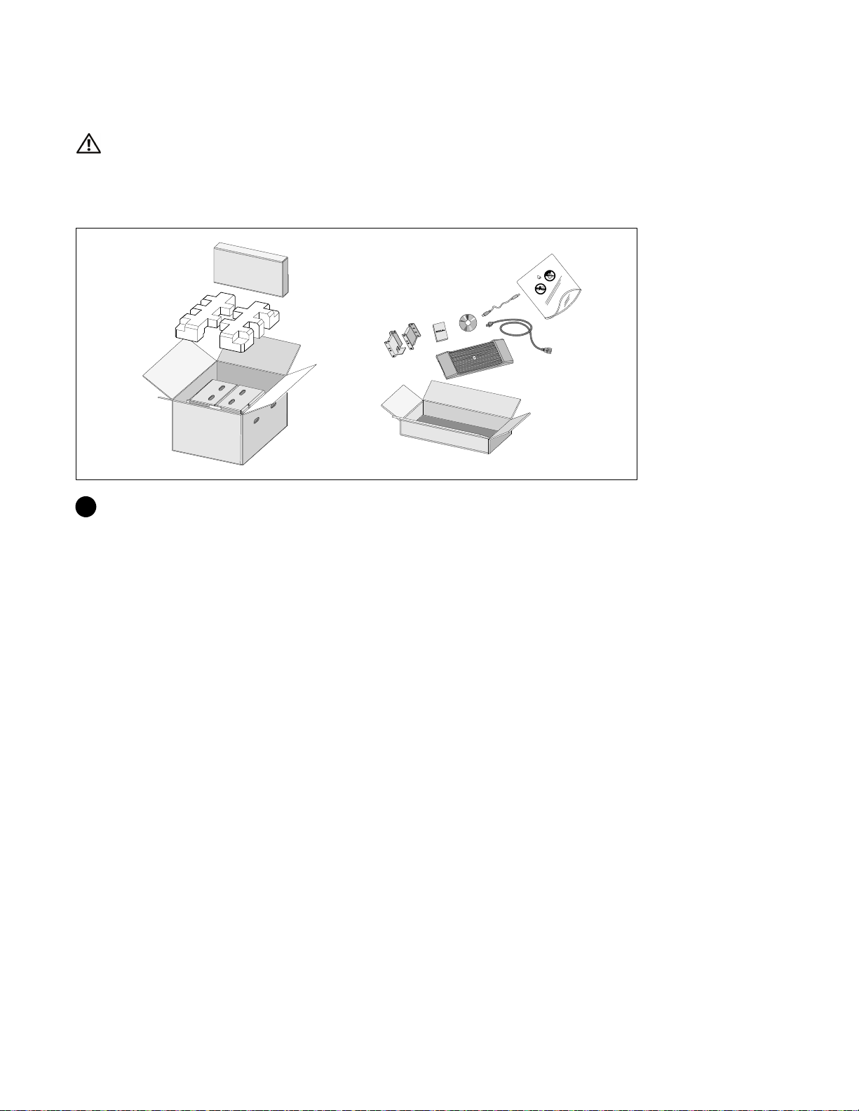
Unpacking the External Battery Module
1 Open the outer carton and remove the accessories packaged with the cabinet.
|
4
Installation and Startup
Page 7
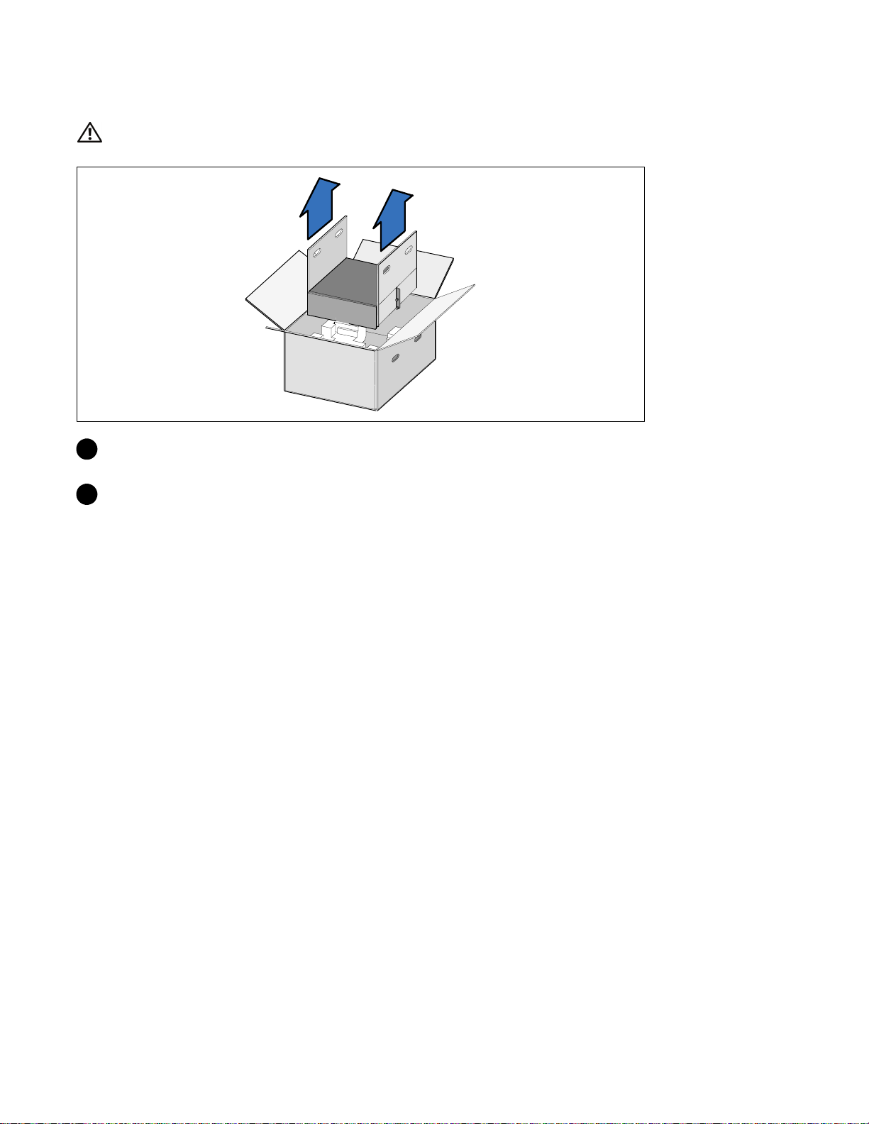
Lifting the Cabinet
CAUTION: The cabinet is heavy (51.8 kg/114.2 lb). Lifting the cabinets into the rack requires a minimum of two
people.
1 Withonepersononeachside,carefullyliftthecabinet out of the outer carton using the handles
on the cardboard and set it on a flat, stable surface.
2 Discard or recycle the packaging in a responsible manner, or store it for future use.
Installation and Startup
|
5
Page 8

Rackmount Setup
CAUTION: The cabinet is heavy (51.8 kg/114.2 lb). Lifting the cabinets into the rack requires a minimum of two
people.
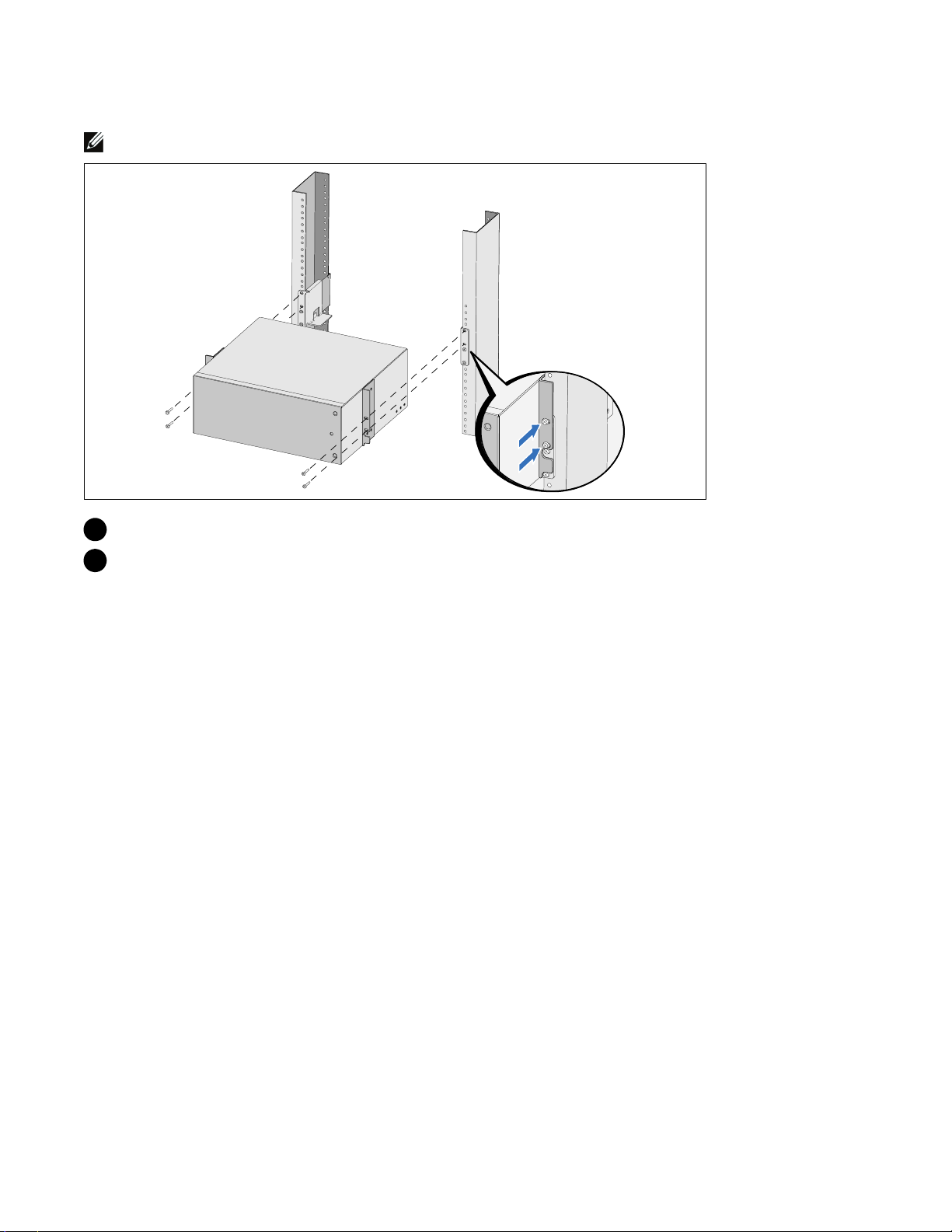
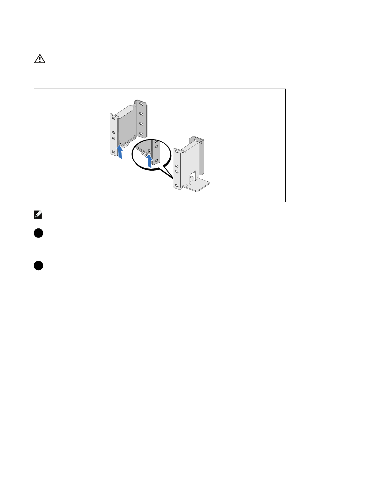
Positioning the Rails
NOTE: The instructions are the same for square-hole racks and unthreaded, round-hole racks. The rails fit both
rack styles. The round-hole rack is shown in the illustrations.
1 Select the proper holes in the rail for positioning the cabinet in the desired location in the rack.
The rails should be located at the bottom of the 3U space allocated for the EBM.
2 Position the end of the left and right rails labeled L and R facing inward.
|
6
Installation and Startup
Page 9

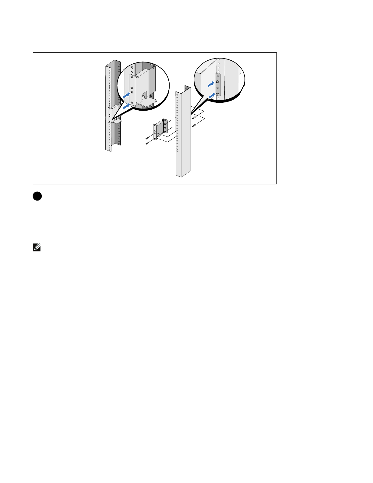
Attaching the Rails to the Rack
3 Attach the rails to the rack:
Adjust the rail so that the flanges fit outside the C-shaped vertical rail.
Secure the rail using the supplied #12-24 Phillips head screws (four for each rail). Use the bottom
two holes for the front of the rail. Use the second and fourth holes for the back of the rail.
NOTE:
If the vertical rail has square holes, use a square nut (not supplied) with the supplied #12-24
Phillips-head screw.
Installation and Startup
|
7
Page 10
Installing the Cabinet
NOTE: Install the EBM directly below the UPS.
4 Slide the cabinet into the rack.
5 Secure the cabinet to the rack using the supplied #12-24 Phillips-head screws (two on each side).
|
8
Installation and Startup
Page 11
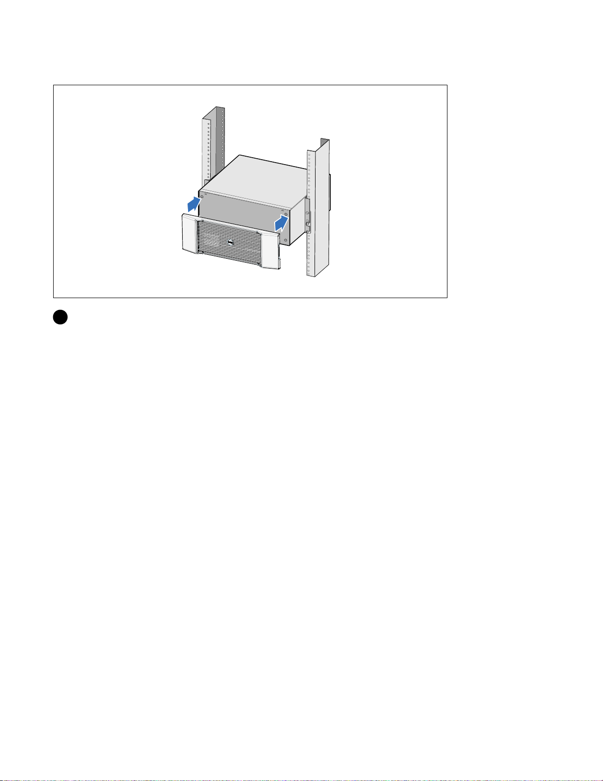
Installing the EBM Front Cover
6 Install the EBM front cover.
Installation and Startup
|
9
Page 12
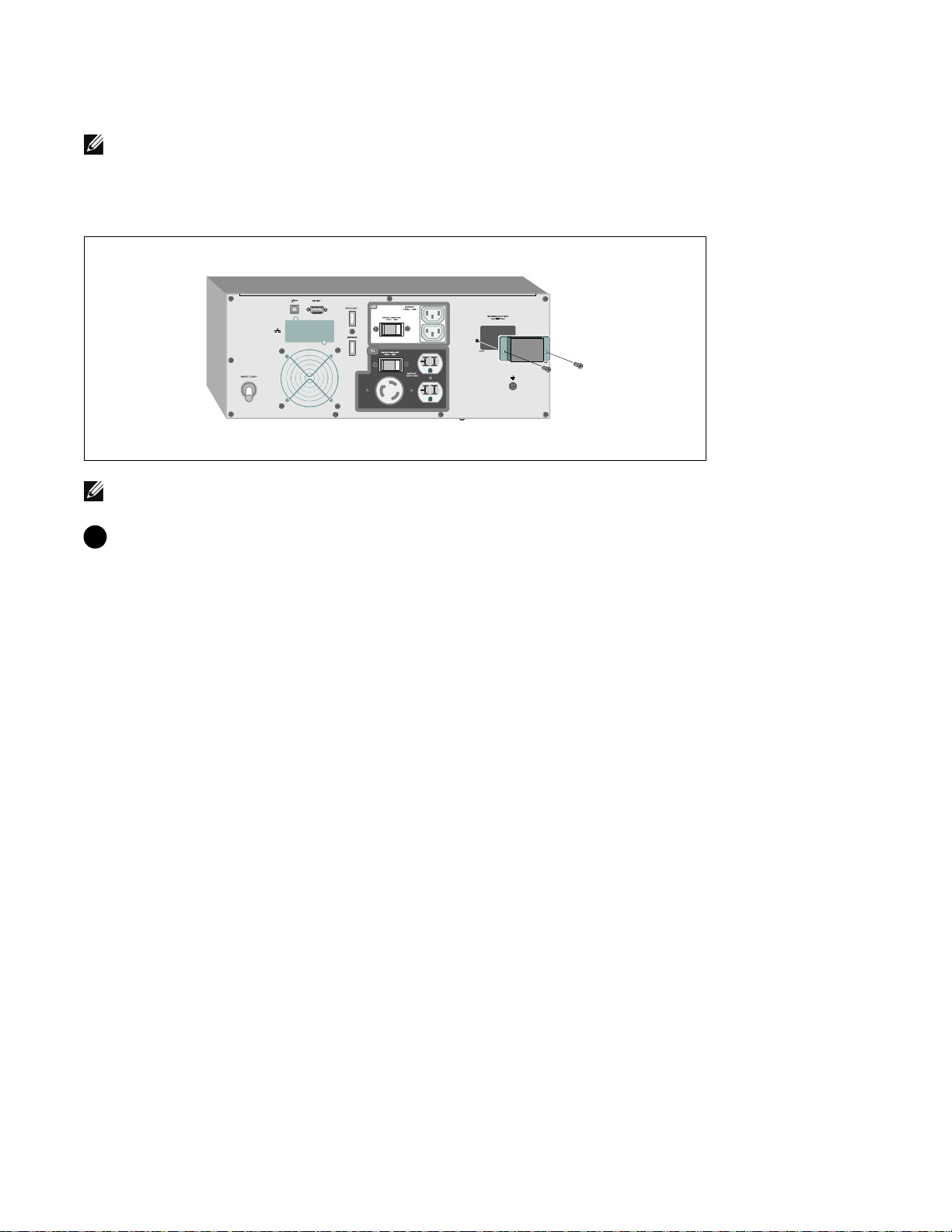
Connecting the EBM
NOTE: A small amount of arcing may occur when connecting an EBM to the UPS. This is normal and will not
harm personnel. Insert the EBM cable into the UPS battery connector quickly and firmly.
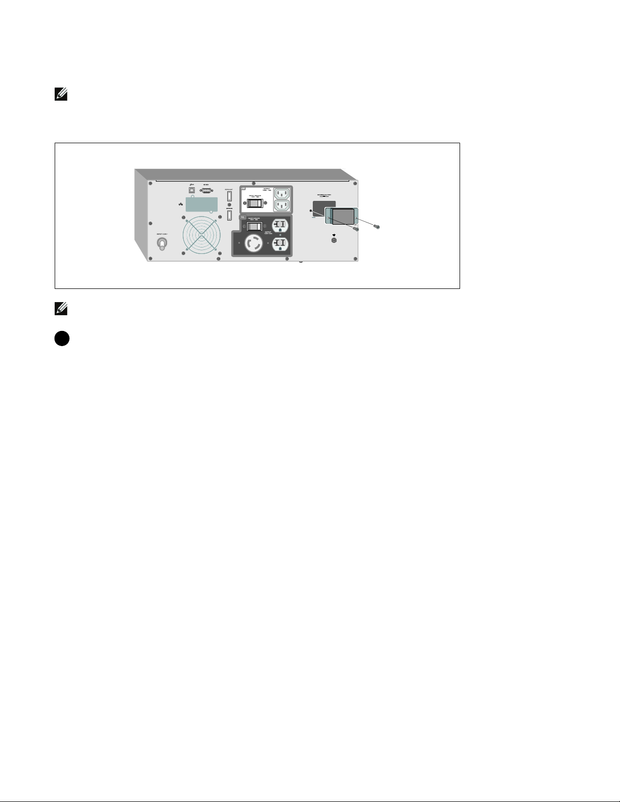
Removing the Battery Connector Cover
NOTE: If the UPS is stored or used without an EBM, the battery connector cover must be installed as a safety
precaution.
1 Remove the battery connector cover from the rear panel. Retain the cover and screws.
10
|
Installation and Startup
Page 13
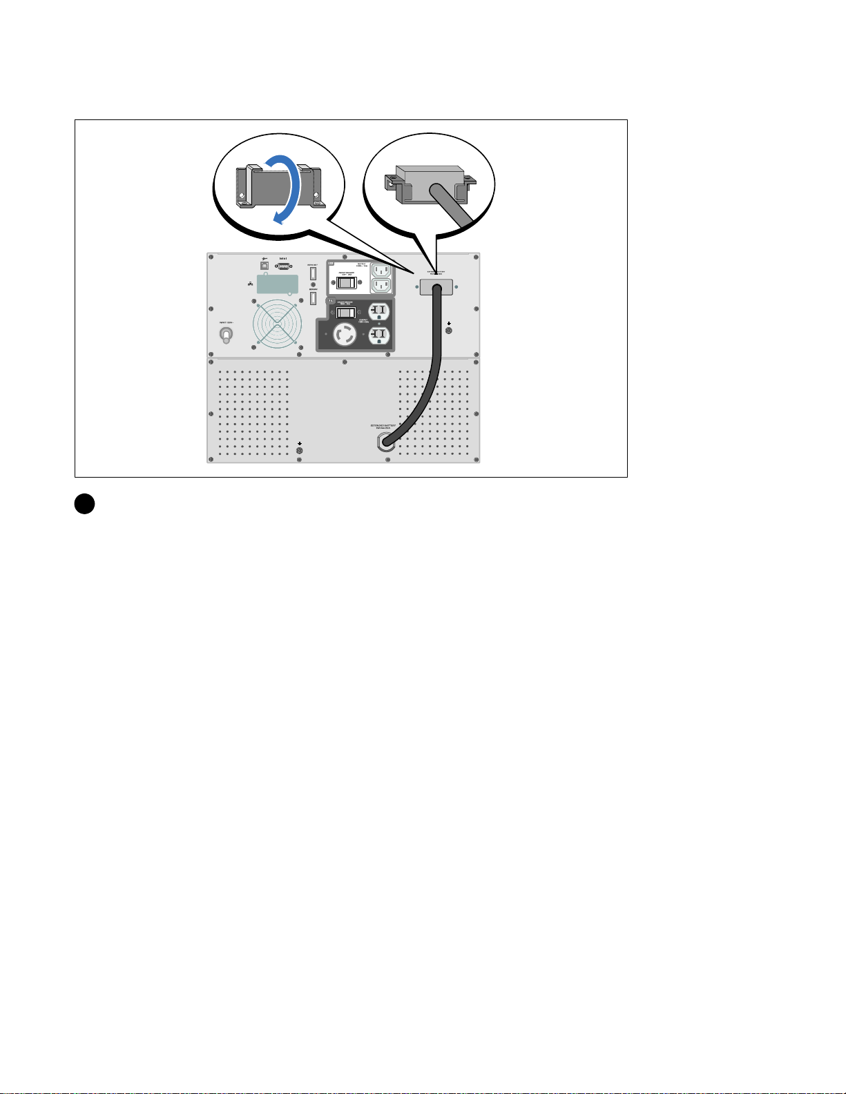
Installing the Strain Relief Bracket
2 Install the battery connector cover under the EBM cable to provide strain relief.
Rotate the battery connector cover on its side and position under the EBM cable.
Installation and Startup
|
11
Page 14

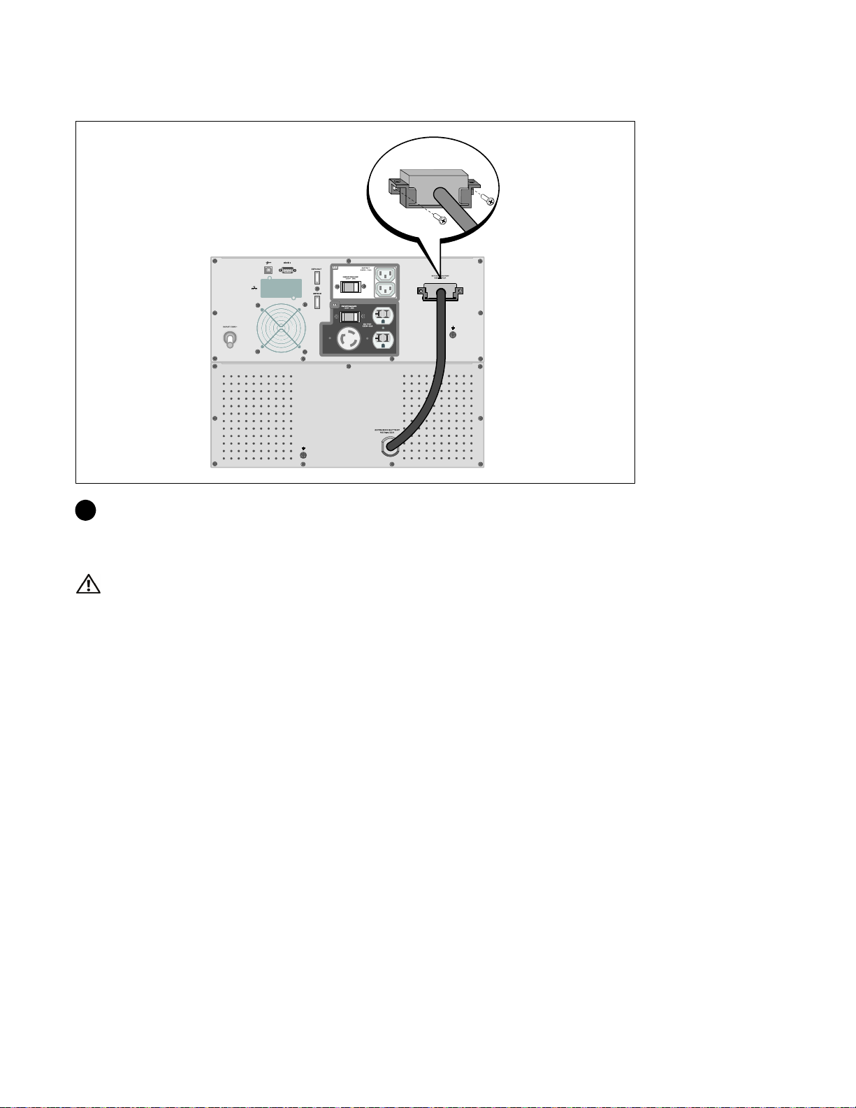
Connecting the EBM Cable
3 Plug the EBM cable into the UPS battery connector.
Secure the battery connector cover to the UPS rear panel using the screws removed in Step 1.
CAUTION:
User's Guide for instructions on installing the UPS.
|
12
Follow the instructions in the UPS Getting Started document or the Dell Online Rack UPS 2700W
Installation and Startup
Page 15

Baie En Ligne Dellt
Module de batterie externe
pour une utilisation avec des
modèles d'onduleur 2700 W
Démarrer
Avec Votre Système
www.dell.com | support.dell.com
K803N, H950N, J728N
H967N
Page 16
Remarques et avertissements
REMARQUE : Une REMARQUE indique des informations importantes qui vous aident à mieux utiliser votre logiciel.
DANGER : Un DANGER indique une situation dangereuse imminente qui, si elle n'est pas évitée, provoquera la
mort ou une blessure grave.
AVERTISSEMENT : Un AVERTISSEMENT indique une situation dangereuse potentielle qui, si elle n'est pas évitée,
pourrait provoquer la mort ou une blessure.
ATTENTION : Une MISE EN GARDE indique une situation dangereuse potentielle qui, si elle n'est pas évitée, peut
provoquer une blessure mineure ou modérée ou des dommages matériels.
DANGER : Respectez les instructions suivantes pour aider à empêcher une situation dangereuse qui, si elle n'est
pas évitée, peut provoquer la mort ou des blessures graves :
S Cet onduleur contient des TENSIONS MORTELLES. Toutes les réparations et tous les entretiens
devront être effectués UNIQUEMENT PAR UN PERSONNEL D’ENTRETIEN AGRÉÉ. Aucune
pièce à l’intérieur de cet onduleur NE PEUT ÊTRE ENTRETENUE PAR L’UTILISATEUR.
Les informations figurant dans ce document sont soumises à modifications sans prénotification.
E 2009 Dell Inc. Tous droits réservés.
La reproduction de quelque manière que ce soit sans l’autorisation écrite de Dell Inc. est strictement interdite.
Marques commerciales utilisées dans ce texte : Dell et le logo DELL sont des marques commerciales de Dell Inc. ; Phillips est une marque
commerciale de Phillips Screw Company.
D’autres marques commerciales et noms commerciaux peuvent être utilisés dans ce document pour se référer à des entités revendiquant les
marques et les noms ou à leurs produits. Dell Inc. nie tout intérêt propriétaire dans les marques commerciales et les noms commerciaux qui
ne lui appartenant pas.
Juillet 2009
Page 17
Trouver des informations
ATTENTION : Le document Informations sur la sécurité, l'environnement et la réglementation fournit des
informations importantes sur la sécurité et la réglementation.
Que recherchez-vous ?
S Le guide d'utilisation de mon onduleur
S Leguided'utilisationdemaCartedegestionde
réseau Del l
S Logiciel de gestion d'onduleur Dell
Trouvez-le ici
Disque de l'onduleur Dell
REMARQUE : Les mises à jour des documents et des
logiciels se trouvent sur
S Spécifications
S Comment configurer les paramètres de l'onduleur
S Comment identifier et résoudre des problèmes
S Comment installer un contrôle REPO
S Instructions de sécurité
S Informations sur la réglementation
S Informations sur le recyclage
S Informations sur la garantie
S Termes et conditions (États-Unis uniquement)
S Contrat de licence de l'utilisateur final
S Informations sur l'assistance Site Internet d'Assistance Dell — support.dell.com
Guide d'utilisation de l'onduleur Dell
Le guide d'utilisation est disponible sur le disque de
l'onduleur Dell et sur support.dell.com.
Informations sur la sécurité, l'environnement et la
réglementation
Informations sur l'assistance et la garantie Dell
support.dell.com.
REMARQUE : Sélectionnez votre région ou votre
segment commercial pour voir le site d'assistance
approprié.
Trouver des informations
|
15
Page 18

Installation et démarrage
ATTENTION : Avant de réaliser les procédures de ce document, lisez et suivez les instructions de sécurité et
les informations importantes sur la réglementation qui figurent dans votre document Informations sur la
sécurité, l'environnement et la réglementation.
Déballage du Module de batterie externe
1 Ouvrez le carton extérieur et retirez les accessoires emballés avec le module.
16
|
Installation et démarrage
Page 19

Levage du module
ATTENTION : Le module est lourd (51,8 kg/51,80 kg). Le levage des modules dans la baie exige deux
personnes au minimum.
1 Avec une personne de chaque côté, levez soigneusement le module hors du carton extérieur en
utilisant les poignées du carton et posez-le sur une surface plane et stable.
2 Jetez ou recyclez l'emballage d'une façon responsable, ou conservez-le pour une utilisation
ultérieure.
Installation et démarrage
|
17
Page 20
Configuration en baie
ATTENTION : Le module est lourd (51,8 kg/51,80 kg). Le levage des modules dans la baie exige deux
personnes au minimum.
Positionnement des Rails
REMARQUE : Les instructions sont les mêmes pour les baies à trous carrés et les baies à trous ronds non
filetés. Les rails s'adaptent aux deux styles de baies. La baie à trous ronds est représentée sur les illustrations.
1 Sélectionnez les bons trous dans le rail pour positionner le module à l'emplacement souhaité dans
la baie.
Les rails doivent être placés en bas de l'espace 3U alloué à l'EBM.
2 Positionnez l'extrémité des rails gauches et droits marquée L et R vers l'intérieur.
|
18
Installation et démarrage
Page 21
Fixation des rails à la baie
3 Fixez les rails à la baie :
Réglez le rail pour que les bords s'emboîtent à l'extérieur du rail vertical en forme de C.
Fixez le rail en utilisant les vis à tête Phillips n°12-24 fournies (quatre pour chaque rail). Utilisez
les deux trous inférieurs pour l'avant du rail. Utilisez les deuxième et quatrième trous pour l'arrière
du rail.
REMARQUE :
Phillips n°12-24 fournie.
Si le rail vertical a quatre trous carrés, utilisez un écrou carré (non fourni) avec la vis à tête
Installation et démarrage
|
19
Page 22

Installation du module
REMARQUE : Installez l'EBM directement sous l'onduleur.
4 Glissezlemoduledanslabaie.
5 Fixez le module à la baie en utilisant les vis à tête Phillips n°12-24 fournies (deux de chaque côté).
20
|
Installation et démarrage
Page 23

Installation du couvercle avant de l'EBM
6 Installez le couvercle avant de l'EBM.
Installation et démarrage
|
21
Page 24
Connexion du EBM
REMARQUE : Un petit arc électrique peut survenir lors du branchement d'un EBM à l'onduleur. Ceci est normal
et ne nuira pas au personnel. Insérez le câble EBM dans le connecteur de batterie de l'onduleur rapidement et
fermement.
Retrait du Couvercle du Connecteur des Batteries
REMARQUE : Si l'onduleur est stocké ou utilisé sans un EBM, le couvercle du connecteur des batteries doit
être installé comme mesure de sécurité.
1 Retirez le couvercle du connecteur des batteries du panneau arrière. Retenez le couvercle et les vis.
22
|
Installation et démarrage
Page 25

Installation du Support du Serre-Câble
2 Installez le couvercle du connecteur des batteries sous le câble de l'EBM pour servir de serre-câble.
Tournezlecouvercleduconnecteurdesbatteriessurlecôtéetplacezlesouslecâbledel'EBM.
|
Installation et démarrage
23
Page 26
Connexion du Câble de l'EBM
3 Branchezlecâbledel'EBMauconnecteurdelabatteriedel'onduleur.
Fixez le couvercle du connecteur des batteries au panneau arrière de l'onduleur en utilisant les vis
retirées à l'Etape 1.
ATTENTION :
l'Onduleur en Baie En Ligne 2700 W pour des instructions sur l'installation de l'onduleur.
|
24
Installation et démarrage
Suivez les instructions du document Démarrage de l'Onduleur ou le Guide d'Utilisation de
Page 27

Dellt Online Rack
Externes Batteriemodul
zur Verwendung mit 2700W USV-Typen
Erste Schritte
Mit Ihrem System
www.dell.com | support.dell.com
K803N, H950N, J728N
H967N
Page 28

Hinweise und Warnungen
HINWEIS: Ein HINWEIS macht auf eine wichtige Information aufmerksam, mit deren Hilfe Sie Ihre Software optimal
nutzen können.
GEFAHR: GEFAHR macht auf eine unmittelbar gefährliche Situation aufmerksam, die zum Tod oder schweren
Verletzungen führt, wenn sie nicht vermieden wird.
WARNUNG: WARNUNG macht auf eine potenziell gefährliche Situation aufmerksam, die zum Tod oder zu
Verletzungen führt, wenn sie nicht vermieden wird.
ACHTUNG: ACHTUNG macht auf eine potenziell gefährliche Situation aufmerksam, die zu geringen oder mäßigen
Verletzungen oder Sachschäden führen kann, wenn sie nicht vermieden wird.
GEFAHR: Beachten Sie die folgende Anweisung, um eine unmittelbar gefährliche Situation zu vermeiden, die zum
Tod oder zu schweren Verletzungen führen könnte:
S Diese USV führt LEBENSGEFÄHRLICHE SPANNUNG. Sämtliche Reparatur-- und Wartungsarbeiten
dürfen NUR VON BEFUGTEM WARTUNGSPERSONAL durchgeführt werden. Im Inneren der
USV sind KEINE VOM BENUTZER WARTBAREN TEILE vorhanden.
Unangekündigte Änderungen der Angaben in diesem Dokument vorbehalten.
E 2009 Dell Inc. Alle Rechte vorbehalten.
Die Vervielfältigung, gleich welcher Art, ist ohne schriftliche Genehmigung von Dell Inc. strengstens untersagt.
In diesem Text verwendete Marken: Bei Dell und dem DELL--Logo handelt es sich um Marken der Dell Inc.; Phillips ist eine e ingetragene
Handelsmarke der Phillips Screw Company.
In diesem Dokument können weitere Marken und Handelsnamen verwendet werden, die sich entweder auf die Personen beziehen, die diese
Marken und Na men für sich beanspruchen, oder auf deren Produkte. Dell Inc. verzichtet auf sämtliche ge werblichen Eigentumsrechte an
Marken und Handelsnamen, bei denen es sich nicht um eigene Marken und Handelsnamen handelt.
Juli 2009
Page 29

Auffinden von Informationen
ACHTUNG: Im Dokument Informationen zu Sicherheit, Umweltschutz und Ordnungsvorschriften finden Sie
wichtige Sicherheitshinweise und Informationen zu gesetzlichen Bestimmungen.
Was suchen Sie?
S Die Benutzeranleitung für meine USV
S Die Benutzeranleitung für die Dell
Netzwerkmanagementkarte
S Dell USV Management Software
S Technische Daten
S Anleitung zum Konfigurieren der
USV-Einstellungen
S Behebung von Fehlern und Lösung von P roblemen
S Installation der REPO-Steuerung
S Sicherheitshinweise
S Informationen über Ordnungsvorschriften
S Recycling-Informationen
S Garantieerklärung
S AGB (nur USA )
S Lizenzvereinbarung für Endbenutzer
S Supportinformationen Dell Support-Webseite — support.dell.com
Hier finden Sie es
Die Diskfür die Dell USV
HINWEIS: Dokumente und Softwareaktualisierungen
finden Sie unter support.dell.com.
Benutzeranleitung der Dell USV
Die Benutzeranleitung finden Sie auf der Disk zu der
Dell USV und auch unter support.dell.com.
Informationen zu Sicherheit, Umweltschutz und
Ordnungsvorschriften
Informationen zu Garantie und Support von Dell
HINWEIS: Wählen Sie Ihre Region bzw. Ihre Branche
aus, um die geeignete Support-Website aufzurufen.
Auffinden von Informationen
|
27
Page 30
Installation und Inbetriebnahme
ACHTUNG: Vor der Ausführung der Verfahren in diesem Dokument lesen und befolgen Sie bitte die
Sicherheitshinweise und wichtigen Informationen zu Ordnungsvorschriften in Ihrem Dokument über
Informationen zu Sicherheit, Umweltschutz und Ordnungsvorschriften.
Auspacken des Externes Batteriemodul
1 Öffnen Sie den äußeren Karton, und nehmen Sie die mit dem Gehäuse zusammen verpackten
Zubehörteile heraus.
28
|
Installation und Inbetriebnahme
Page 31

Gehäuse heben
:Das Gehäuse ist schwer (51,8 kg). Zum Heben des Gehäuses in das Gestell sind mindestens zwei Personen
erforderlich.
1 Heben Sie das Gehäuse mit einer Person auf jeder Seite mit den Griffen am Karton vorsichtig aus
dem äußeren Karton heraus, und setzen Sie es auf einer flachen, stabilen Unterlage ab.
2 Entsorgen oder recyceln Sie die Verpackung in umweltbewusster Weise, oder bewahren Sie sie für
denspäterenGebrauchauf.
Installation und Inbetriebnahme
|
29
Page 32

Rackmontage
:Das Gehäuse ist schwer (51,8 kg). Zum Heben des Gehäuses in das Gestell sind mindestens zwei Personen
erforderlich.
Positionierung der Schienen
HINWEIS: Für Gestelle mit quadratischen Öffnungen und Racks mit runden Öffnungen ohne Gewinde gelten die
gleichen Anweisungen. Die Schienen passen zu beiden Gestellarten. Auf den Abbildungen ist das Gestell mit
den runden Öffnungen zu sehen.
1 Wählen Sie die korrekten Öffnungen in der Schiene aus, um das Gehäuse wie gewünscht im Rack
zu positionieren.
Die Schienen sollten an der Unterseite des für die EBM zugewiesenen 3 U-Raums angeordnet
sein.
2 Richten Sie das Ende der linken und rechten Schiene mit der Aufschrift L und R nach innen aus.
|
30
Installation und Inbetriebnahme
Page 33

Anbringen der Schienen am Gestell
3 Bringen Sie die Schienen am Gestell an:
Stellen Sie die Schiene so ein, dass die Flansche außen mit der C-förmigen senkrechten Schiene
zusammenpassen.
Sichern Sie die Schiene mithilfe der enthaltenen #12-24 Philips-Rändelschrauben (vier für jede
Schiene). Verwenden Sie die unteren zwei Löcher für die Schienenvorderseite. Verwenden Sie das
zweite und vierte Loch für die Schienenrückseite.
HINWEIS:
mit dem enthaltenen #12-24 Phillips-Schraubenschlüssel verwenden.
Wenn die senkrechte Schiene rechteckige Löcher aufweist, die rechteckige Nut (nicht enthalten)
|
Installation und Inbetriebnahme
31
Page 34

Installation des Gehäuses
HINWEIS: Bringen Sie die EBM direkt unterhalb der USV an.
4 Schieben Sie das Gehäuse in das Gestell.
5 Sichern Sie das Gehäuse am Gestell mithilfe der enthaltenen #12-24 Philips-Rändelschrauben
(zwei auf jeder Seite).
32
|
Installation und Inbetriebnahme
Page 35

Installation der vorderen EBM-Abdeckung
6 Installieren Sie die vordere EBM-Abdeckung.
Installation und Inbetriebnahme
|
33
Page 36

Anschluss EBM
HINWEIS: Beim Anschließen eines EBM an die USV kann es zu einem kleinen Lichtbogen kommen. Dies ist
normal und für Personen unschädlich. Verbinden Sie das EBM-Kabel rasch und fest mit dem Batterieanschluss
der USV.
Entfernen der Batterieanschlussabdeckung
HINWEIS: Sollte die USV ohne eine EBM gelagert oder verwendet werden, muss die
Batterieanschlussabdeckung aus Sicherheitsgründen installiert sein.
1 Entfernen Sie die Batterieanschlussabdeckung von der Rückseite. Entfernen Sie die Abdeckung
und Schrauben.
34
|
Installation und Inbetriebnahme
Page 37

Installation der Druckausgleichsklammer
2 Installieren Sie die Batterieanschlussabdeckung unter dem EBM-Kabel, um einen Druckausgleich
zu gewährleisten.
Drehen Sie die Batterieanschlussabdeckung auf die Seite, und positionieren Sie diese unter dem
EBM-Kabel.
|
Installation und Inbetriebnahme
35
Page 38

Anschluss des EBM-Kabels
3 Stecken Sie das EBM-Kabel in den USV-Batterieanschluss ein.
Sichern Sie die Batterieanschlussabdeckung an der hinteren Abdeckung der USV. Benutzen Sie
hierzu die in Schritt 1 entfernten Schrauben.
ACHTUNG:
für das Dell Online Rack 2700W für Anweisungen zur Installation der USV.
|
36
Folgen Sie den Anweisungen aus dem Dokument Erste Schritte USV oder der Benutzeranleitung
Installation und Inbetriebnahme
Page 39

Стойка онлайнового ИБП Dellt
Модуль внешней батареи
для использования с
моделями 2700 Вт
Начало работы
c вашей системой
www.dell.com | support.dell.com
K803N, H950N, J728N
H967N
Page 40

Примечания и предупреждения
ПРИМЕЧАНИЕ: Пометка ПРИМЕЧАНИЕ указывает на важную информацию, которая поможет
вам более эффективно использовать свое программное обеспечение.
ОПАСНОСТЬ: Пометка ОПАСНОСТЬ указывает на ситуации, в которых существует
непосредственная угроза, которая, если ее не избежать, приведет к серьезной травме или
летальному исходу.
ПРЕДУПРЕЖДЕНИЕ: Пометка ПРЕДУПРЕЖДЕНИЕ указывает на потенциально опасную
ситуацию, которая, если ее не избежать, может привести к травме или летальному исходу.
ВНИМАНИЕ: Пометка ВНИМАНИЕ указывает на потенциально опасную ситуацию, которая,
если ее не избежать, может привести к травмам легкой и средней степени тяжести или к
повреждению имущества.
ОПАСНОСТЬ: Следуйте приведенным ниже инструкциям, позволяющим предупредить
непосредственную угрозу, которая, если ее не избежать, приведет к серьезной травме или
летальному исходу:
S В устройстве ИБП некоторые узлы находятся под СМЕРТЕЛЬНО ОПАСНЫМ
НАПРЯЖЕНИЕМ. Все работы по ремонту и обслуживанию должны выполняться
ТОЛЬКО УПОЛНОМОЧЕННЫМ ОБСЛУЖИВАЮЩИМ ПЕРСОНАЛОМ.ВИБПНЕТ
УЗЛОВ, ОБСЛУЖИВАЕМЫХ ПОЛЬЗОВАТЕЛЕМ.
Информация в настоящем документе может быть изменена без предварительного уведомления.
E 2009 Dell Inc. Все права защищены.
Воспроизведение данного документа любым способом без письменного разрешения компании Dell Inc. категорически
запрещено.
Торговые знаки, используемые в данном тексте: Dell и логотип DELL являются торговыми знаками компании Dell Inc.;
Phillips является зарегистрированными торговыми марками Phillips Screw Company.
Прочие торговые знаки и торговые марки могут использоваться в данном документе для ссылки на организации,
предъявляющие права на эти знаки и марки или на соответствующие товары. Dell Inc. отказывается от любого права
собственности на какие-либо торговые знаки или торговые марки, кроме своих собственных.
Июнь 2009 г.
Page 41

Поиск информации
ВНИМАНИЕ: Документ Информация о технике безопасности, охране окружающей
среды и нормативная информация содержит важную информацию о технике
безопасности и нормативную информацию.
Что вы ищете?
S Руководство пользователя для моего ИБП
S Руководство пользователя для карты Карта
сетевого управления Dell
S Программа управления ИБП Dell
Вы найдете это здесь
Диск ИБП Dell
ПРИМЕЧАНИЕ: Документация и обновленные
версии ПО можно найти на сайте
support.dell.com.
S Спецификации
S Как конфигурировать настройки ИБП
S Как находить и устранять неисправности и
решать проблемы
S Как установить управление REPO
S Инструкции по технике безопасности
S Нормативная информация
S Информация об утилизации
S Информация о гарантии
S Условия и положения (только для США)
S Лицензионное соглашение с конечным
пользователем
S Информация о поддержке Веб-сайт техподдержки Dell —
Руководство пользователя ИБП Dell
Руководство пользователя доступно на диске
support.dell.com.
Информация о технике безопасности, охране
окружающей среды и нормативная
информация
Информация о гарантии и поддержке Dell
support.dell.com
ПРИМЕЧАНИЕ: Выберите свой регион или
сегмент бизнеса, чтобы увидеть
соответствующий сайт поддержки.
Поиск информации
|
39
Page 42

Установка и запуск
ВНИМАНИЕ: Перед выполнением процедур, описанных в данной документации,
прочтите и выполните инструкции по технике безопасности и ознакомьтесь с важной
нормативной информацией, которая содержится в документе Информация о технике
безопасности, охране окружающей среды и нормативная информация.
Модуль внешней батареи - Распаковка
1 Откройте внешнюю картонную коробку и достаньте из нее принадлежности,
упакованные вместе с корпусом.
|
40
Установка и запуск
Page 43

Подъем корпуса
ВНИМАНИЕ: Корпус тяжелый (51,8 кг). Для подъема корпуса на стойку требуется не
менее двух человек.
1 Два человека (по одному человеку с каждой стороны) должны осторожно вынуть
корпус из картонной упаковки за ручки на картоне и установить его на ровной
устойчивой поверхности.
2 Выбросьте или утилизируйте упаковку согласно правилам или сохраните ее для
будущего использования.
Установка и запуск
|
41
Page 44

Вариант установки в стойке
ВНИМАНИЕ: Корпус тяжелый (51,8 кг). Для подъема корпуса на стойку требуется не
менее двух человек.
Установка на направляющие
Примечание: Инструкции по работе со стойками с квадратными отверстиями и стойками с
круглыми безрезьбовыми отверстиями одинаковые. Направляющие подходят для обоих
видов стоек. Стойка с круглыми отверстиями показана на рисунке.
1 Выберите надлежащие отверстия в направляющих для размещения корпуса в
желаемом месте стойки.
Направляющие должны располагаться в нижней части пространства 3U,
выделенного для МВБ.
2 Поместите концы правой и левой направляющих с меткамиLиRвовнутрь.
|
42
Установка и запуск
Page 45

Крепление направляющих к стойке
3 Прикрепите направляющие к стойке:
Установите направляющую таким образом, чтобы фланцы зашли за вертикальную
рейку в форме буквы C.
Закрепите направляющую при помощи винтов №12-24 с головкой Phillips, которые
входят в комплект поставки (четыре на каждую направляющую). Для передней
части направляющей используйте два нижних отверстия. Используйте второе и
четвертое отверстия для задней части направляющей.
Примечание:
квадратную гайку (в комплект поставки не входит) и винт №12-24 с головкой Phillips (входит в
комплект поставки).
Если в вертикальной стойке отверстия квадратной формы, используйте
Установка и запуск
|
43
Page 46

Установка корпуса
Примечание: Установите МВБ непосредственно под ИБП.
4 Задвиньте корпус в стойку.
5 Прикрепите корпус к стойке при помощи винтов №12-24 с головкой Phillips (входят в
комплект поставки) (по два с каждой стороны).
44
|
Установка и запуск
Page 47

Установка передней крышки МВБ
6 Установите переднюю крышку МВБ.
Установка и запуск
|
45
Page 48

Подключение МВБ
Примечание: При подключении МВБ к ИБП может возникнуть незначительное искрение.
Это нормально и не опасно для персонала. Вставляйте кабель МВБ в разъем батарей ИБП
быстро и прочно.
Снятие крышки разъема батарей
Примечание: Если ИБП хранится или используется без МВБ, крышка разъема батарей
должна быть установлена на место в качестве меры предосторожности.
1 Снимите крышку разъема батарей с задней панели. Отложите крышку и винты в
сторону.
46
|
Установка и запуск
Page 49

Установка скобы натяжения
2 Установите крышку разъема батарей под кабель МВБ, чтобы снизить натяжение.
Поверните крышку разъема батарей на бок и установите под кабелем МВБ.
Установка и запуск
|
47
Page 50

Подключение кабеля МВБ
3 Подключите кабель МВБ к разъему батарей.
Прикрепите крышку разъема батарей к задней панели ИБП при помощи винтов,
которые вы вынули на этапе 1.
ВНИМАНИЕ:
2700 Вт при установке в стойке.
|
48
Установка и запуск
При установке ИБП следуйте инструкциям, которые приведены в
Начало работы с ИБП или Руководство пользователя онлайнового ИБП Dell
Page 51

Bastidor en línea de Dellt
Módulo de batería externa
para uso con modelos de UPS 2700W
Inicio
de su sistema
www.dell.com | support.dell.com
K803N, H950N, J728N
H967N
Page 52

Notas y advertencias
NOTA: Una NOTA indica información impo rtante que lo ayuda a utilizar mejor el software.
PELIGRO: Un PELIGRO indica una situación in minentemente peligrosa que, si no se evita, dará como resultado la
muerte o una lesión grave.
ADVERTENCIA: Una ADVERTENCIA indica una situación potencialmente peligrosa que, si no se evita, podría dar
como resultado la muerte o una lesión.
PRECAUCIÓN: Una PRECAUCIÓN indica una situación potencialmente peligrosa que, si no se evita, puede dar
como resultado una lesión moderada o leve, o incidentes de daños a la propiedad.
PELIGRO: Cumpla con las siguientes instrucciones para evitar una situación inminentemente peligrosa que, de no
evitarse, dará como resultado la muerte o una lesión grave:
S Este UPS contiene VOLTAJES LET ALES. SÓLO EL PERSONAL DE SERVICIO AUTORIZADO
debe realizar las reparaciones y el servicio. NO HAY PIEZAS QUE PUEDAN RECIBIR SERVICIO
DEL USUARIO dentro de un UPS.
La información de este documento se encuentra sujeta a cambios sin previo aviso.
E 2009 Dell Inc. Todos los derechos reservados.
Queda estrictamente prohibida cualquier forma de reproducción sin el previo consentimiento de Dell Inc. por escrito.
Marcas comercia les utilizadas en este texto: Dell yellogotipodeDELL son marcas comerciales de Dell Inc.; Phillips es una marca
registrada de Phillips Screw Company.
Es posible que en este documento se utilicen otras marcas y nombres comerciales para hacer referencia a las entidades que responden a
dichas marcas y nombres o a sus productos. Dell Inc. niega cualquier interés en la propiedad de las marcas y nombres comerciales de
terceros.
Julio de 2009
Page 53

Búsqueda de información
PRECAUCIÓN: El documento Información ambiental, regulatoria y de seguridad brinda información
regulatoria y sobre seguridad importante.
¿Qué está buscando?
S La guía del usuario para mi UPS
S La guía del usuario para la Tarjeta de gestión de red
de Dell
S Software de gestión de UPS de Dell
Encuéntrelo aqu
Disco del UPS de Dell
NOTA: La documentación y la actualización de software
se pueden encontrar en
S Especificaciones
S Cómo configurar los valores del UPS
S Cómo localizar averías y resolver problemas
S Cómo instalar el control REPO
S Instrucciones de seguridad
S Información regulatoria
S Información sobre reciclado
S Información sobre seguridad
S Términos y condiciones (sólo EE. UU.)
S Acuerdo de licencia del usuario final
S Información sobre soporte Sitio Web de soporte de Dell: support.dell.com
Guía del usuario del UPS de Dell
La guía del usuario está disponible en el disco del UPS
de Dell y en support.dell.com.
Información ambiental, regulatoria y de seguridad
Información sobre soporte y garantía de Dell
support.dell.com.
NOTA: Seleccione su región o segmento de negocio
para visualizar el sitio de soporte correspondiente.
Búsqueda de información
|
51
Page 54

Instalación y arranque
PRECAUCIÓN: Antes de realizar los procedimientos que se describen en este documento, lea y cumpla con
las instrucciones de seguridad y la información regulatoria importante en su documento Información
ambiental, regulatoria y de seguridad.
Cómo desembalar el Módulo de batería externa
1 Abra la caja de cartón exterior y extraiga los accesorios embalados con el gabinete.
52
|
Instalación y arranque
Page 55

Elevación del gabinete
PRECAUCIÓN: El gabinete es pesado (51,8 kg/51,80 kg). Para levantar los gabinetes al bastidor se necesitan
al menos dos personas.
1 Conunapersonadecadalado,levantecuidadosamenteelgabinetedelacajadecartónexterna
usando las manijas de la caja de cartón y colóquelo sobre una superficie plana y estable.
2 Deseche o recicle el embalaje de manera responsable o guárdelo para referencia futura.
Instalación y arranque
|
53
Page 56

Configuración del montaje en bastidor
PRECAUCIÓN: El gabinete es pesado (51,8 kg/51,80 kg). Para levantar los gabinetes al bastidor se necesitan
al menos dos personas.
Cómo colocar los rieles
NOTA: Las instrucciones son las mismas que para los bastidores de orificios cuadrados y los bastidores de
orificios redondos y sin rosca. Los rieles sirven para ambos estilos de bastidores. En las ilustraciones se
muestra el bastidor con orificios redondos.
1 Seleccione los orificios adecuados en el riel para posicionar el gabinete en la ubicación deseada en
el bastidor.
Se deben ubicar los rieles en la parte inferior del espacio 3U para EBM.
2 Coloque el extremo de los rieles derecho e izquierdo con la etiqueta R y L hacia adentro.
|
54
Instalación y arranque
Page 57

Cómo sujetar los rieles al bastidor
3 Sujete los rieles con el bastidor:
Ajuste el riel de modo que las pestañas encajen fuera del riel vertical en forma de C.
Asegure el riel con los tornillos de cabeza Phillips N.°12-24 suministrados (cuatro para cada riel).
Use los dos orificios inferiores para el frente del riel. Use el segundo y el cuarto orificio para la
parte posterior del riel.
NOTA:
Si el riel vertical tiene orificios cuadrados, use una tuerca cuadrada (no provista) con el tornillo de
cabeza Phillips N.°12-24 suministrado.
Instalación y arranque
|
55
Page 58

Instalación del gabinete
NOTA: Instale el EBM directamente debajo del UPS.
4 Deslice el gabinete por el bastidor.
5 Asegure el gabinete al bastidor con los tornillos de cabeza Phillips N.°12-24 suministrados (dos de
cada lado).
56
|
Instalación y arranque
Page 59

Cómo instalar la cubierta frontal del EBM
6 InstalelacubiertafrontaldelEBM.
Instalación y arranque
|
57
Page 60

Cómo conectar el EBM
NOTA: Puede haber un pequeño arco al momento de conectar un EBM al UPS. Esto es normal y no ocasionará
daños personales. Inserte el cable del EBM en el conector de la batería del UPS de forma rápida y firme.
Cómo retirar la cubierta del conector
NOTA: Si el UPS se almacena o se utiliza sin un EBM, la cubierta del conector de la batería debe instalarse
como precaución de seguridad.
1 Retire la cubierta del conector de la batería del panel posterior. Conserve la cubierta y los tornillos.
58
|
Instalación y arranque
Page 61

Cómo instalar el soporte de tubo pasacables
2 Instale la cubierta del conector de la batería debajo del cable del EBM para proporcionar un
tubo pasacables.
Gire la cubierta del conector de la batería hacia su lado y colóquela debajo del cable del EBM.
Instalación y arranque
|
59
Page 62

Cómo conectar el cable del EBM
3 Enchufe el cable del EBM en el conector de la batería del UPS.
Asegure la cubierta del conector de la batería al panel posterior del UPS con los tornillos que quitó
en el paso 1.
PRECAUCIÓN:
bastidor en línea 2700W de Dell para obtener indicaciones sobre cómo instalar el UPS.
|
60
Instalación y arranque
Siga las instrucciones del documento UPS Getting Started olaGuía del usuario del UPS con
Page 63

Dellt 在线机架式
外部电池模块
用于 2700W UPS 型号
系统使用
入门指南
www.dell.com | support.dell.com
K803N, H950N, J728N
H967N
Page 64

注意和警告
注意: “注意”表示可帮助您更好使用本软件的重要信息。
危险: “危险”表示紧急危险情况,如果不加以避免,将导致死亡或严重的伤害。
警告: “警告”表示潜在危险情况,如果不加以避免,可能会导致死亡或伤害。
小心: “小心”表示潜在危险情况,如果不加以避免,可能导致轻度或中度伤害,或财产损失事故。
危险: 遵守下列须知有助于防止紧急危险情况,其若不加以避免,将导致死亡或严重的伤害:
S 本 UPS 包含危险致命的电压。 所有维修和服务都只能由经过授权的维修人员进行。 UPS
中没有用户可自行维修的部件。
本文档所含信息如有更改,恕不另行通知。
© 2009 Dell Inc. 保留所有权利。
未经 Dell Inc. 书面允许,严禁以任何形式进行复制。
本文中使用的商标: Dell 和 DELL 徽标是 Dell Inc. 的商标; Phillips 是 Phillips Screw Company 的注册商标。
本文件中可能会使用其它商标或商业名称来指称拥有该商标或名称权利的实体或其产品。 Dell Inc.
对不属于自己的商标和商品名称,不拥有任何产权利益。
2009 年 7 月
Page 65

查找信息
小心:
您正在寻找什么?
S 我的 UPS 的用户指南
S Dell 网络管理卡 用户指南
S Dell UPS 管理软件
S 规格
S 如何配置 UPS 设置
S 如何诊断故障和解决问题
S 如何安装 REPO 控制
S 安全操作说明
S 行政法规信息
S 回收信息
S 保修信息
S 条款和条件(仅限美国)
S 最终用户许可协议
S 支持信息
安全、环保和法规信息
文件提供了重要的安全和法规信息。
在此查找
Dell UPS 光盘
注意: 文件和软件更新可在 support.dell.com
找到。
Dell UPS 用户指南
用户指南可从 Dell UPS 光盘和 support.dell.com
上找到。
安全、环保和法规信息
Dell 保修和支持信息
Dell 支持网站 — support.dell.com
注意: 选择您的区域或业务部门,
以查看合适的支持网站。
查找信息
|
63
Page 66

安装和启动
小心:在进行本文件中的步骤之前,请先阅读和遵循
文件中的安全操作说明和重要法规信息。
拆开外部电池模块包装
1 打开外部包装箱,取下与机箱包装在一起的配件。
安全、环保和法规信息
64
|
安装和启动
Page 67

举起机箱
小心:机箱很重 (51.8 kg)。 将机箱抬起放入机架至少需要两个人。
1 一人一边使用纸板上的手柄小心将机箱从外面的纸箱中取出,并放到平坦、稳定的平面上。
2 以环保的方式处理包装材料或回收循环利用,或者收起存放以备将来使用。
安装和启动
|
65
Page 68

机架安装
小心:机箱很重 (51.8 kg)。 将机箱抬起放入机架至少需要两个人。
定位导轨
注意: 方孔机架和无螺纹的圆孔机架的操作说明相同。 导轨适用于这两种机架。
图中所示为圆孔机架。
1 选择导轨中合适的孔将机箱定位于机架中所需的位置。
导轨应位于分配给 EBM 的 3U 空间底部。
2 面向内放置贴有“左”(L) 和“右”(R) 的左右导轨的末端。
|
66
安装和启动
Page 69

将导轨连接到机架上
3 将导轨连接到机架上:
调整导轨,以使得法兰与 C 型垂直导轨的外部配合好。
用提供的 #12-24 十字头型螺钉(每个导轨四个)固定导轨。 导轨前端使用底部的两个孔。
导轨后端使用第二和第四个孔。
注意:
如果垂直导轨具有方孔,则为提供的 #12-24 十字头型螺钉配用方形螺母(未提供)。
安装和启动
|
67
Page 70

安装机箱
注意: 将 EBM 直接安装在 UPS 下方。
4 将机箱滑入机架中。
5 用提供的 #12-24 十字头型螺钉(每侧两个)将机箱固定在机架上。
68
|
安装和启动
Page 71

安装 EBM 前盖。
6 安装 EBM 前盖。
安装和启动
|
69
Page 72

连接 EBM
注意: 连接 EBM 和 UPS 时可能会出现少量火花。 这是正常现象,不会对人员产生伤害。 将 EBM
线缆迅速稳固地插入 UPS 电池连接器中。
取下电池连接器盖
注意:如果 UPS 在无 EBM的情况下储存或使用,作为一项安全措施,必须安装电池连接器盖。
1 从后面板上取下电池连接器盖。 保留外盖和螺钉。
70
|
安装和启动
Page 73

安装应变消除支架
2 将电池连接器盖安装在EBM电缆下方,以提供应变消除。
以侧边旋转电池连接器盖,并放置在 EBM 电缆下方。
安装和启动
|
71
Page 74

连接 EBM 电缆
3 将EBM电缆插入 UPS 电池连接器。
用步骤 1 中取下的螺钉将电池连接器盖固定在 UPS 后面板上。
小心:
的说明。
72
|
安装和启动
按照 UPS
入门指南
文件中的说明或
Dell 在线机架式 2700W 用户指南
中有关安装 UPS
Page 75

Dellt 在綫式機架
外部電池模組
用於 2700W UPS 型號
系統使用
入門指南
www.dell.com | support.dell.com
K803N, H950N, J728N
H967N
Page 76

注意和警告
注意: 「注意」表示可協助您更妥善地使用本軟體的重要資訊。
危險: 「危險」表示緊急危險情況,如果不加以避免,將導致死亡或嚴重的傷害。
警告: 「警告」表示潛在危險情況,如果不加以避免,將會導致死亡或嚴重的傷害。
小心: 「小心」表示潛在危險情況,如果不加以避免,可能導致輕度或中度傷害,或財產損失事故。
危險: 遵守以下須知有助於防止緊急危險情況,其若不加以避免,將導致死亡或嚴重的傷害:
S 本 UPS 包含 危險致命的電壓。 所有維修和服務都只能由 經過授權的維修人員 進行。 UPS 中
沒有可由使用者自行維修的零件。
本文件所含資訊如有變更,恕不另行通知。
© 2009 Dell Inc. 保留所有權利。
未經 Dell Inc. 書面允許,嚴格禁止以任何形式進行複製。
本文中使用的商標: Dell 和 DELL 標誌是 Dell Inc. 的商標; Phillips 是 Phillips Screw Company 的註冊商標。
本文件中可能會使用其它商標或商業名稱來指稱擁有該商標或名稱權利的實體或其產品。 Dell Inc.
對不屬於自己的商標和商業名稱,不擁有任何產權利益。
2009 年 7 月
Page 77

尋找資訊
小心:
安全、環保和法規資訊
文件提供了重要的安全和法規資訊。
您要尋找什麼?
S 我的 UPS 的使用者指南
S Dell 網路管理卡 使用者指南
S Dell UPS 管理軟體
S 規格
S 如何進行 UPS 設定
S 如何診斷故障和解決問題
S 如何安裝 REPO 控制
S 安全操作說明
S 法規資訊
S 回收資訊
S 保固資訊
S 條款和條件(僅限美國)
S 一般使用者授權協議
S 支援資訊
在此尋找
Dell UPS 光碟
注意: 文件和軟體更新可在 support.dell.com 取得。
Dell UPS 使用者指南
使用者指南可從 Dell UPS 光碟和 support.dell.com
上取得。
安全、環保和法規資訊
Dell 保固和支援資訊
Dell 支援網站 — support.dell.com
注意: 請選擇您的區域或業務部門,
以查看合適的支援網站。
尋找資訊
|
75
Page 78

安裝和啟動
小心: 在進行本文件中的步驟之前,請先閱讀並遵循
文件中的安全操作說明和重要法規資訊。
拆開 外部電池模組包裝
1 打開外部包裝箱,取下與機箱包裝在一起的配件。
安全、環保和法規資訊
76
|
安裝和啟動
Page 79

抬起機箱
小心: 機箱很重 (51.8kg/114.2lb)。 將機箱抬起放入機架至少需要兩個人。
1 一人一邊使用紙板上的握把小心地將機箱從外面的紙箱中取出,並放到平坦、
穩定的平面上。
2 以環保的方式棄置包裝材料或進行回收,或是收存以備將來使用。
安裝和啟動
|
77
Page 80

機架安裝
小心: 機箱很重 (51.8kg/114.2lb)。 將機箱抬起放入機架至少需要兩個人。
定位導軌
注意: 方孔機架和無螺紋的圓孔機架的操作說明相同。 導軌適用於這兩種機架。
圖中所示為圓孔機架。
1 請選擇導軌中合適的孔,將機箱固定於機架中所要的位置。
導軌應位於分配給 EBM 的 3U 空間底部。
2 將貼有「左」(L) 和「右」(R) 的左右導軌的末端面向內放置。
|
78
安裝和啟動
Page 81

將導軌連接到機架上
3 將導軌連接到機架上:
調整導軌,使法蘭與 C 型垂直導軌的外部緊密配合。
使用提供的 #12-24 十字頭螺釘(每個導軌四個)固定導軌。 導軌前端使用底部的兩個孔。
導軌後端使用第二和第四個孔。
注意:
如果垂直導軌是方孔,請使用與提供的 #12-24 十字頭螺釘相配合的方形螺母(未提供)。
安裝和啟動
|
79
Page 82

安裝機箱
注意: 將 EBM 直接安裝在 UPS 下方。
4 將機箱滑入機架中。
5 使用提供的 #12-24 十字頭螺釘(每側兩個)將機箱固定在機架上。
80
|
安裝和啟動
Page 83

安裝 EBM 前蓋
6 安裝 EBM 前蓋。
安裝和啟動
|
81
Page 84

連接 EBM
注意: 連接 EBM 和 UPS 時可能會出現少量電弧。 這是正常現象,不會對人員產生傷害。 將 EBM
纜線迅速穩固地插入 UPS 電池接頭中。
取下電池接頭蓋
注意: 如果在沒有 EBM 的時候存放或者使用 UPS,則必須安裝電池接頭蓋以作為安全措施。
1 從後面板上取下電池接頭蓋。 保留蓋子和螺釘。
82
|
安裝和啟動
Page 85

安裝應力消除支架
2 將電池接頭蓋安裝在 EBM 電纜下方,以提供應力消除。
以側面旋轉電池接頭蓋,並放置在 EBM 電纜下方。
安裝和啟動
|
83
Page 86

連接 EBM 電纜
3 將 EBM 電纜插入 UPS 電池接頭。
使用步驟 1 中取下的螺釘,將電池接頭蓋固定在 UPS 後面板上。
小心:
UPS 的說明。
84
|
安裝和啟動
請遵循 UPS
入門指南
文件中的說明或 Dell
在綫機架式
UPS 2700W
使用者指南
中有關安裝
Page 87

Dellt 온라인 랙
외장 배터리 모듈
함께 사용 2700W UPS 모델
사용자의 시스템
시작하기
www.dell.com | support.dell.com
K803N, H950N, J728N
H967N
Page 88

참고및경고
참고: “참고”는 소프트웨어를 더 잘 활용하는 데 도움이 되는 중요한 정보를 나타냅니다.
위험: “위험”은 피하지 않을 경우 급박한 위험 상황이 사망이나 중상의 결과를 야기할 수 있음을
나타냅니다.
경고: “경고”는 피하지 않을 경우 죽음이나 상해를 야기할 수 있는 잠재적 위험 상황을 표시합니다.
주의: “주의”는 피하지 않을 경우 경미하거나 보통의 상해 또는 재산 손실 사고를 야기할 수 있는 잠재적
위험 상황을 표시합니다.
위험: 아래의 지시사항을 준수하여 피하지 않을 경우 사망이나 중상의 결과를 야기할 수 있는 급박한 위험
상황을 방지하십시오:
S UPS는 사망에이를수있는전압을 갖고 있습니다. 모든 수리와 정비는 자격있는 서비스 요원만이
수행해야 합니다. UPS 내부에는 사용자가 정비할 수 없는 부품이 있습니다.
이 문서에 포함된 정보는 고지없이 변경될 수 있습니다.
© 2009 Dell Inc. All rights reserved.
Dell Inc.의 서면 허락 없이 어떤 방식으로든 복제하는 것은 엄격히 금지됩니다.
이 문서에서 사용된 상표: Dell 과 DELL 로고는 Dell Inc.의 상표입니다. Phillips 는 Phillips Screw Company의 등록 상표입니다.
기타 상표와 상호를 관련 상표 및 명칭 또는 관련 제품에 대한 권리를 가지는 당사자를 지칭하기 위해 이 문서에서 사용할 수
있습니다. Dell Inc. 는 Dell Inc.가 소유하지 않은 상표 및 상호에 대한 재산적 이해관계를 부인합니다.
2009년7월
Page 89

정보 찾아보기
주의:
안전, 환경, 및 규제 관련 정보
문서는 중요한 안전 및 규제 정보를 제공합니다.
찾는 정보 항목
S UPS용 사용자 설명서
S Dell 네트워크 관리카드 용 사용자 설명서
S Dell UPS Management Software
S 사양
S UPS 설정 구성 방법
S 장애 처리 및 문제점 해결
S REPO 제어 설치 방법
S 안전 지침
S 규제 정보
S 재활용 정보
S 보증 정보
S 약관 (미국만 해당)
S 최종사용자 라이센스 계약
S 지원 정보
정보의 소재
Dell UPS디스크
참고: 문서 및 소프트웨어 업데이트는
support.dell.com 에서 조회할 수 있습니다.
Dell UPS 사용자 설명서
사용자 설명서는 Dell UPS 디스크 및 support.dell.com
에서 조회할 수 있습니다.
안전, 환경, 및 규제 관련 정보
Dell 보증및지원정보
Dell 지원 웹사이트 — support.dell.com
참고: 적절한 지원 사이트를 보려면 해당 지역이나
사업분야를 선택하십시오.
정보 찾아보기
|
87
Page 90

설치및시작
주의: 본 문서의 절차를 수행하기 전에
규제정보를 읽고 준수하십시오.
안전, 환경, 및 규제 관련 정보
외장 배터리 모듈 포장 풀기
1 포장상자를 열고 캐비닛과 함께 포장된 부속품을 꺼내십시오.
문서에 있는 안전 지침 및 중요한
88
|
설치및시작
Page 91

캐비닛 들어올리기
주의: 캐비닛은 무겁습니다(51.8 kg/114.2 lb). 캐비닛을 랙 안으로 들어 올려 넣으려면 최소한 2인이
필요합니다.
1 양편에 각 한 사람이 자리한 후, 판지의 손잡이를 이용하여 포장상자에서 캐비닛을
조심스럽게 들어 올려 평평하고 안정된 지면에 내려 놓으십시오.
2 포장은 해당 처리방식에 따라 폐기하거나 재활용하십시오. 또는 추후 사용하려면
보관하십시오.
설치및시작
|
89
Page 92

랙장착설치
주의: 캐비닛은 무겁습니다(51.8 kg/114.2 lb). 캐비닛을 랙 안으로 들어 올려 넣으려면 최소한 2인이
필요합니다.
레일 위치 정하기
참고: 사각 구멍 랙과 나사산 없는 원형 구멍 랙에 대해 설치 지침은 동일합니다. 레일은 두 종류의
랙에 모두 맞습니다. 원형 구멍 랙은 그림에서 볼 수 있습니다.
1 캐비닛을 랙의 원하는 위치에 설치할 적당한 구멍을 레일에서 선택합니다.
레일은 EBM에 할당된 3U 공간 하단에 위치해야 합니다.
2 L 및 R로 표시된 좌우 레일의 끝을 안쪽을 향하게 합니다.
|
90
설치및시작
Page 93

레일을 랙에 부착하기
3 다음과 같이 레일을 랙에 부착합니다:
플랜지가 C형 수직 레일 바깥에 잘 맞도록 레일을 조정합니다.
공급되는 #12-24 필립스 헤드스크류(각 레일용으로 4개)를 사용하여 레일을
고정시키십시오. 레일 앞면에는 하단 2개 구멍을 이용합니다. 레일의 뒷면에는 2번째
구멍과 4번째 구멍을 이용합니다.
참고:
버티컬 레일에 사각형 구멍이 있다면, 공급되는 #12-24 필립스-헤드 스크류를 갖춘 사각형
너트(비공급)를 사용합니다.
설치및시작
|
91
Page 94

캐비닛 설치하기
참고: UPS 바로 아래에 EBM을 설치합니다.
4 캐비닛을 랙으로 밀어 넣습니다.
5 공급되는 #12-24 필립스 헤드스크류(각 면에 2개)를 사용하여 캐비닛을 랙에
고정시키십시오.
92
|
설치및시작
Page 95

EBM 앞면 커버 설치하기
6 EBM 앞면 커버를 설치합니다.
설치및시작
|
93
Page 96

연결하기 EBM
참고: EBM을 UPS에 연결할 때 소량의 아크(arc)가 발생할 수 있습니다. 이것은 정상적인 것이며
인체에 해를 주지 않습니다. EBM 케이블을 UPS 배터리 커넥터에 신속하고 단단히 삽입합니다.
배터리 커넥터 커버 분리하기
참고: EBM 없이 UPS를 보관하거나 사용할 경우, 배터리 커넥터 커버를 설치해야 합니다.
1 뒷면 패널에서 배터리 커넥터 커버를 분리합니다. 커버와 스크류를 잘 보관합니다.
94
|
설치및시작
Page 97

응력 완화 브래킷 설치
2 배터리 커넥터 커버를 EBM 케이블 아래에 설치하여 케이블이 팽팽하지 않게 합니다.
배터리 커넥터 커버를 돌려 EBM 케이블 아래에 위치시킵니다.
설치및시작
|
95
Page 98

EBM 케이블 연결하기
3 EBM 케이블을 UPS 배터리 커넥터에 꽂습니다.
1 단계에서 분리한 나사를 사용하여 배터리 커넥터 커버를 UPS 뒷면 패널에 고정시킵니다.
주의:
96
UPS 설치에 대한 지시사항에 대해서는 UPS
가이드
에 있는 지시사항을 따르십시오.
|
설치및시작
시작
문서 또는
Dell 온라인 랙 UPS 2700W 사용자
Page 99

Dellt ラインインタラクティブ式ラック
外付けバッテリーモジュール
以下での使用 2700W UPS 型
はじめに
システムについて
www.dell.com | support.dell.com
K803N、 H950N、 J728N
H967N
Page 100

注意および警告
注記: 「注記」は、ソフトウェアを有効に利用するための重要な情報を示しています。
危険: 「危険」は、回避しないとほぼ確実に死亡、または重傷を招く危険な状況を示しています。
警告: 「警告」は、回避しないと死亡、または重傷を招く潜在的に危険な状況を示しています。
注意: 「注意」は、回避しないと軽傷、または中程度の傷害を招く恐れがある潜在的に危険な状況を
示しています。
危険: 回避しないとほぼ確実に死亡、または重傷を招く危険な状況を防ぐため、以下の説明をよく
お読みください:
S このUPSの中には 致死的な電圧 が掛かっています。すべての修理や点検は、公認のサー
ビススタッフのみ. が行わなければいけません。UPS内には ユーザーが修理可能な部品は
ありません。
当資料の情報は、予告なく変更されることがあります。
E 2009 Dell Inc. 無断複写・転載を禁じます。
Dell Inc.の書面による許可のない複写は、いかなる形態においても厳重に禁じられています。
当テキストに使用されている登録商標: Dell および DELL のロゴは、Dell Inc.の登録商標です。Phillips は、Phillips Screw
Companyの登録商標です。
本書に使用されているその他の登録商標および商標名は、商標や名称を主張する事業体、あるいは製品のいずれかに言及
します。 Dell Inc.は、Dell自身が所有する登録商標および商標権におけるいかなる所有権を一切放棄します。
2009年7月
 Loading...