

Page 1

Dell UltraSharp U3417W Monitor
User’s Guide
Model: U3417W
Regulatory model: U3417Wb
Page 2

Notes, cautions, and warnings
NOTE: A NOTE indicates important information that helps you make better
use of your computer.
CAUTION: A CA
UTION indicates potential damage to hardware or loss of
data if instructions are not followed.
WARNING: A WARNING indicates a potential for property damage,
personal injury, or death.
____________________
Copyright © 2016 Dell Inc. All rights reserved.
This product is protected by U.S. and international copyright and intellectual property laws.
TM
Dell
and the Dell logo are trademarks of Dell Inc. in the United States and/or other
jurisdictions. All other marks and names mentioned herein may be trademarks of their
respective companies.
2016 - 06 Rev. A00
Page 3

Contents
About Your Monitor . . . . . . . . . . . . . . . . . . . . . . . . . . . . . . . . . . . . 5
Package Contents . . . . . . . . . . . . . . . . . . . . . . . . . . . . . . . . . . . . . . . . . . . . .5
Product Features . . . . . . . . . . . . . . . . . . . . . . . . . . . . . . . . . . . . . . . . . . . . . .7
Identifying Parts and Controls . . . . . . . . . . . . . . . . . . . . . . . . . . . . . . . . . .8
Monitor Specifications . . . . . . . . . . . . . . . . . . . . . . . . . . . . . . . . . . . . . . . .12
Plug and Play Capability . . . . . . . . . . . . . . . . . . . . . . . . . . . . . . . . . . . . . . .21
Universal Serial Bus (USB) Interface. . . . . . . . . . . . . . . . . . . . . . . . . . . . .21
LCD Monitor Quality and Pixel Policy . . . . . . . . . . . . . . . . . . . . . . . . . . 22
Maintenance Guidelines. . . . . . . . . . . . . . . . . . . . . . . . . . . . . . . . . . . . . . 23
Setting Up the Monitor . . . . . . . . . . . . . . . . . . . . . . . . . . . . . . . . 24
Attaching the Stand. . . . . . . . . . . . . . . . . . . . . . . . . . . . . . . . . . . . . . . . . . 24
Connecting Your Monitor . . . . . . . . . . . . . . . . . . . . . . . . . . . . . . . . . . . . 27
Organizing Your Cables . . . . . . . . . . . . . . . . . . . . . . . . . . . . . . . . . . . . . . .31
Removing the Monitor Stand . . . . . . . . . . . . . . . . . . . . . . . . . . . . . . . . . 32
Wall Mounting (Optional). . . . . . . . . . . . . . . . . . . . . . . . . . . . . . . . . . . . . 32
Operating the Monitor. . . . . . . . . . . . . . . . . . . . . . . . . . . . . . . . . 34
Power On the Monitor . . . . . . . . . . . . . . . . . . . . . . . . . . . . . . . . . . . . . . . 34
Using the Front Panel Controls . . . . . . . . . . . . . . . . . . . . . . . . . . . . . . . 34
Contents | 3
Page 4

Using the On-Screen Display (OSD) Menu. . . . . . . . . . . . . . . . . . . . . . 36
Setting the Maximum Resolution. . . . . . . . . . . . . . . . . . . . . . . . . . . . . . .57
Using the Tilt, Swivel, and Vertical Extension . . . . . . . . . . . . . . . . . . . 58
Troubleshooting . . . . . . . . . . . . . . . . . . . . . . . . . . . . . . . . . . . . . . 60
Self-Test . . . . . . . . . . . . . . . . . . . . . . . . . . . . . . . . . . . . . . . . . . . . . . . . . . . . 60
Built-in Diagnostics . . . . . . . . . . . . . . . . . . . . . . . . . . . . . . . . . . . . . . . . . . 61
Common Problems . . . . . . . . . . . . . . . . . . . . . . . . . . . . . . . . . . . . . . . . . . 62
Product Specific Problems . . . . . . . . . . . . . . . . . . . . . . . . . . . . . . . . . . . 64
Universal Serial Bus (USB) Specific Problems . . . . . . . . . . . . . . . . . . . 65
Speakers Specific Problems. . . . . . . . . . . . . . . . . . . . . . . . . . . . . . . . . . . 65
Appendix . . . . . . . . . . . . . . . . . . . . . . . . . . . . . . . . . . . . . . . . . . . . . 66
FCC Notices (U.S. Only) and Other Regulatory Information . . . . . . 66
Contact Dell. . . . . . . . . . . . . . . . . . . . . . . . . . . . . . . . . . . . . . . . . . . . . . . . . 66
4 | Contents
Page 5
About Your Monitor
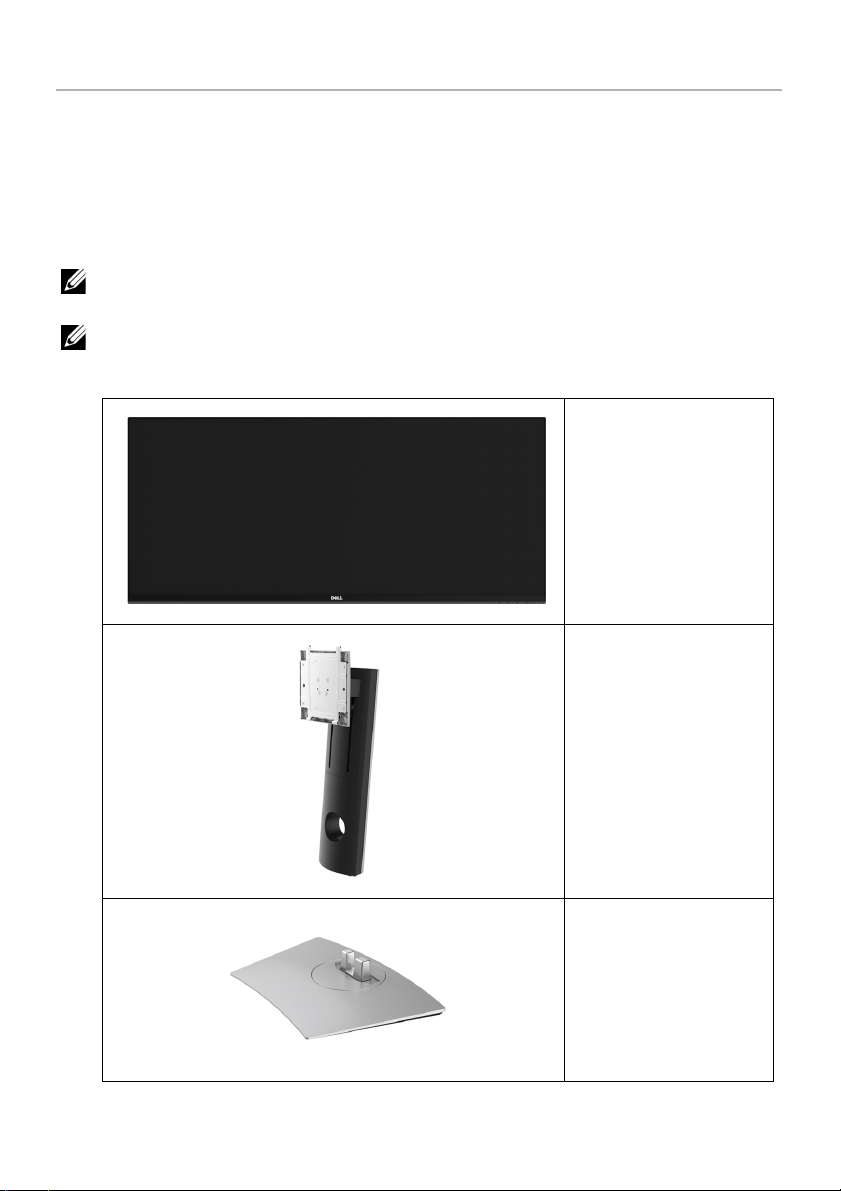
Package Contents
Your monitor ships with the components shown below. Ensure that you have received all
the components and
NOTE: Some items may be o
features or media may not be available in certain countries.
NOTE: To set up with any other stand, please refer to the respective stand setup
guide
for setup instructions.
Contact Dell
if something is missing.
ptional and may not ship with your monitor. Some
Monitor
Stand Riser
Stand Base
About Your Monitor | 5
Page 6
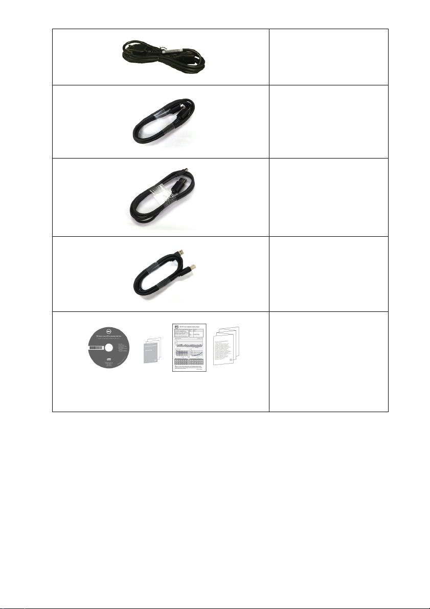
Power Cable (Varies by
Countries)
HDMI Cable
DP Cable (Mini-DP to DP)
USB 3.0 Upstream Cable
(Enables the USB Ports on
the Monitor)
• Drivers and
Documentation Media
• Quick Setup
• Factory Calibration
Repor
• Safety, Environmental,
and Regulatory
Information
Guide
t
6 | About Your Monitor
Page 7

Product Features
The Dell U3417W flat panel display has an active matrix, Thin-Film Transistor (TFT), Liquid
Crystal Display (LCD) and LED backlight. The monitor features include:
• 86.7 cm (34-inch) viewable area display (measured diagonally).
3440 x 1440 resolution, plus full-screen support for lower resolutions.
• Wide viewing angle to allow viewing from a sitting or standing position.
• T
ilt, swivel, and vertical extension adjustment capabilities.
• Ultra-thin bezel minimizes the bezel gap in multi-monitor usage, enabling easier
set up with an elegant viewing experience.
• Removable s
mounting holes for flexible mounting solutions.
• Plug and play capability if supported by your system.
• Color gamu
• On-Screen Display (OSD) adjustments for ease of set-up and screen optimization.
• So
ftware and documentation media includes an Information File (INF), Image Color
Matching File (ICM), and product documentation.
• Dell Display Manager Software included (comes in the CD shipped with the
monitor).
• Security loc
• Stand lock.
• Capability
the image quality.
• High Dynamic Contrast Ratio (5,000,000:1).
• 0
.5 W standby power when in the sleep mode.
• Ene
• Optimize eye comfort with a flicker-free screen and ComfortView feature which
• Suppor
rgy Gauge shows the energy level being consumed by the monitor in real time.
minimizes blue light emission.
tand and Video Electronics Standards Association (VESA™) 100 mm
t of 99% sRGB with an average Delta E < 3.
k slot.
to switch from wide aspect to standard aspect ratio while maintaining
ts Picture by Picture (PBP) and Picture in Picture (PIP) Select mode.
About Your Monitor | 7
Page 8
Identifying Parts and Controls
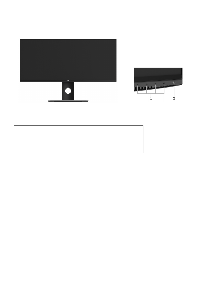
Front View
Front panel controls
Label
1 Function buttons (For more information, see
Operating the Monitor
2 Power On/Off button (with LED indicator)
Description
)
8 | About Your Monitor
Page 9
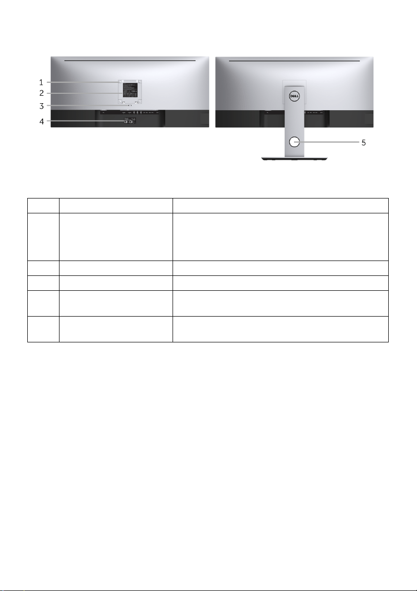
Back View
Back view with monitor stand
Label
1 VESA mounting holes
2 Regulatory label Lists the regulatory approvals.
3 Stand release button Releases stand from monitor.
4 Barcode serial number
5 Cable management slot Use to organize cables by placing them through
Description Use
Wall mount monitor using VESA-compatible wall
00 mm x 100 mm -
(1
behind attached VESA
Cover)
l
labe
mount kit (100 mm x 100 mm).
to this label if you need to contact Dell for
Refer
technical support.
the slot.
About Your Monitor | 9
Page 10
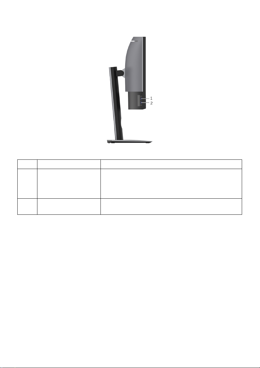
Side View
Label
1 USB downstream port Connect your USB device. You can only use this
2 USB downstream port
* To avoid signal interference, when a wireless USB device has been connected to a USB
downstream port, it is NOT recommended to connect any other USB devices to the
adjacent port(s).
Description Use
ter you have connected the USB cable to
with Power
Ch
connector af
the computer and USB upstream connector on the
monitor.*
Connect to charge your device.
arging
10 | About Your Monitor
Page 11
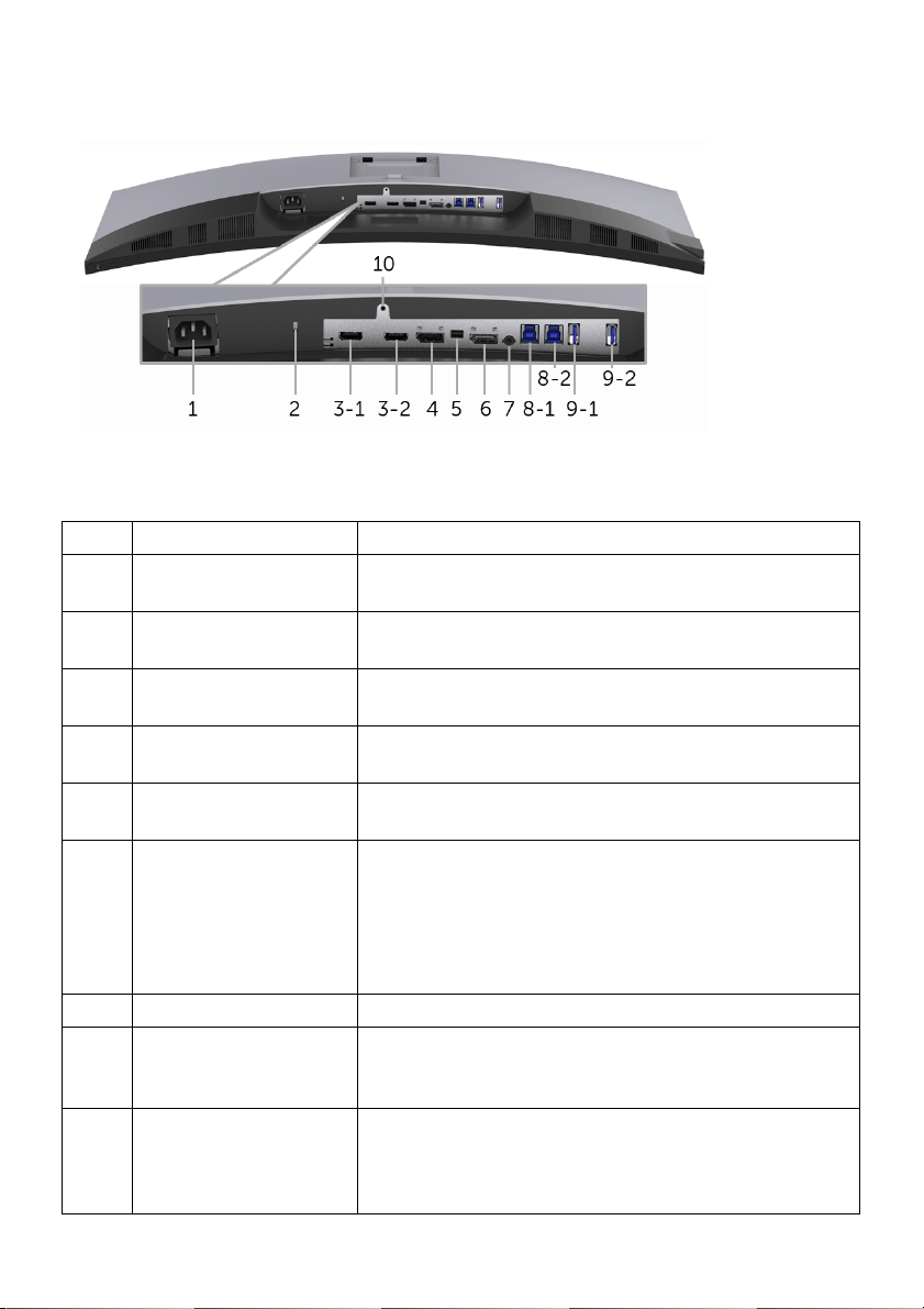
Bottom View
Bottom view without monitor stand
Label Description Use
1 AC power cord
connector
2 Security lock slot Secures monitor with security lock (security lock not
HDMI port connector Connect your computer with HDMI cable.
3
)
(1, 2
4 DisplayPort in
connector
5 Mini DisplayPort in
connector
6 DisplayPort out (MST)
connector
7 Audio-Line out Connect your speakers.*
USB upstream port Connect the USB cable that came with your monitor
8
, 2
)
(1
9-1 USB downstream port Connect your USB device. You can only use this
nect the power cable.
Con
included).
Co
nnect your computer with DP cable.
nnect your computer with Mini-DP to DP cable.
Co
layPort output for MST (Multi-Stream Transport)
Disp
capable monitor. DP 1.1 monitor can only be
connected as the last monitor in the MST chain. To
enable MST, refer to instruction on section
Connecting the monitor for DP Multi-Stream Transport
"
(MST) function
to the computer. Once this cable is connected, you
can use the USB connectors on the monitor.
ector af
conn
the computer and USB upstream connector on the
monitor.**
".
ter you have connected the USB cable to
About Your Monitor | 11
Page 12

9-2 USB downstream port
with Power Charging
10 Stand lock feature To lock the stand to the monitor using a M3 x 6 mm
Connect to charge your device.
rew (screw not included).
sc
* Headphone usage is not supported for the audio line out
** To avoid signal interference, when a wireless USB dev
downstream port, it is NOT recommended to connect any other USB devices to the
adjacent port(s).
connector.
ice has been connected to a USB
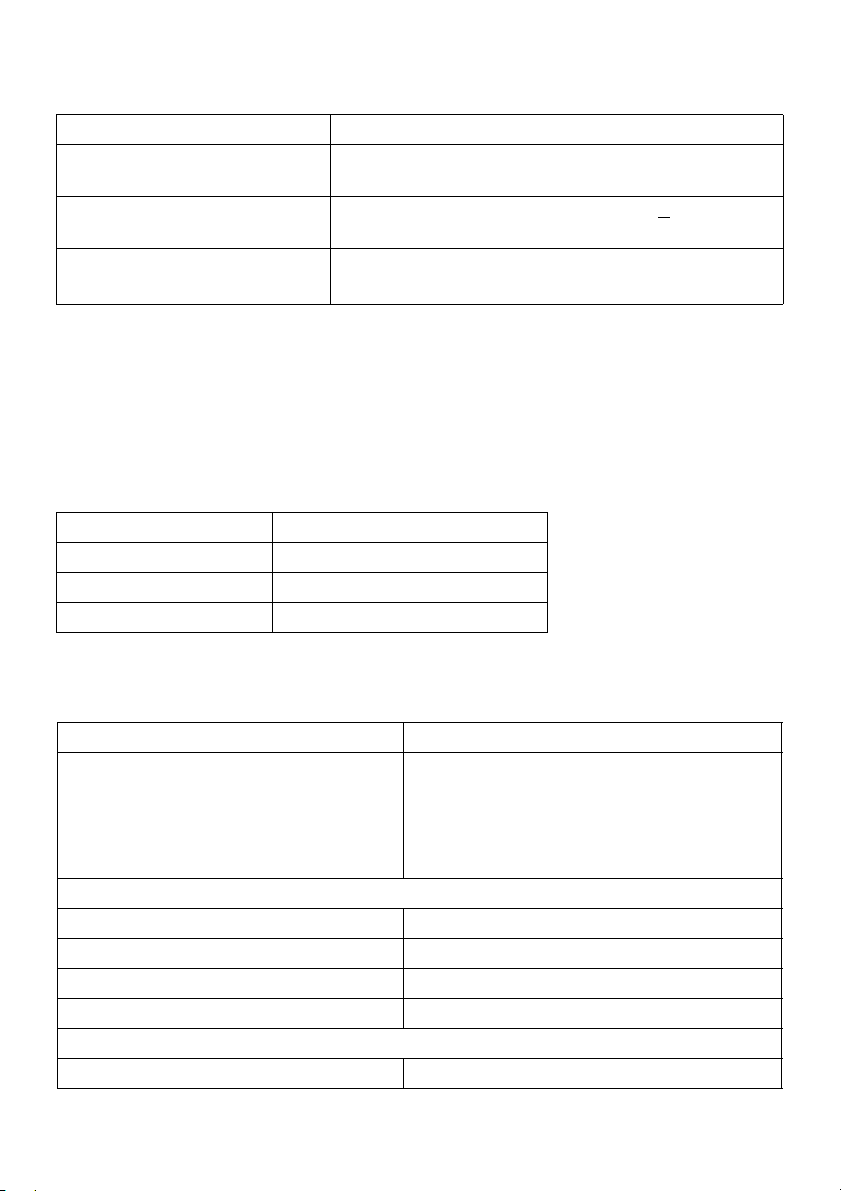
Monitor Specifications
Flat Panel Specifications
Model U3417W
Screen type Active matrix - TFT LCD
Panel technology In-Plane Switching Type
Viewable image
Diagonal
Horizontal, Active Area
Vertical, Active Area
Area
Pixel pitch 0.233 mm x 0.233 mm
Pixel per inch 109
Viewing angle 178° (vertical) typical
Luminance output 300 cd/m² (typical)
Contrast ratio 1000 to 1 (typical)
Faceplate coating Anti-Glare with 3H hardness
Backlight LED edgelight system
Response time 8 ms (typical) for NORMAL mode
Color depth 1.074 billion colors
Color gamut sRGB 99%, CIE1976 (90%), and CIE 1931 (75%)
867.2 mm (34.14 inches)
799.80 mm (31.49 inches)
334.80 mm (13.18 inches)
2
267773.04 mm
178° (horizontal) typical
5M to 1 (typical Dynamic Contrast On)
5 ms (typical) for FAST mode
(415.01 inch2)
12 | About Your Monitor
Page 13
Built-in devices • USB 3.0 super-speed hub (with 2 x USB 3.0 upstream
port
)
• 4 x USB 3.
Connectivity • 2 x HDMI 2.0
• 1 x DP 1.2
• 1 x mDP
• 1 x DP Output
• 2 x USB 3.0 port - Upstream
• 2 x USB 3.0 port - Side
• 2 x USB 3.0 port - Bottom
10.55 mm (Top)
10.05 mm (Left/Right)
0 to 115 mm
-5° to 21°
-30° to 30°
N/A
Yes
• Anti-theft stand lock slot (to panel)
y
t
dge of
ea)
Border width (e
monitor to active ar
Adjustability
Height adjustable stand
Ti lt
Swivel
Pivot
Dell Display Manager
Compatibili
Security • Security lock slot (cable lock sold separately)
0 downstream ports
Resolution Specifications
el U3417W
Mod
Horizontal scan range 30 kHz to 134 kHz (automatic)
Vertical scan range 48 Hz to 76 Hz (automatic)
Maximum preset resolution 3440 x 1440 at 60 Hz
Supported Video Modes
Model U3417W
Video display capabilities
(HDMI & DP playback)
480p, 480i, 576p, 720p, 1080p, 576i, 1080i
About Your Monitor | 13
Page 14
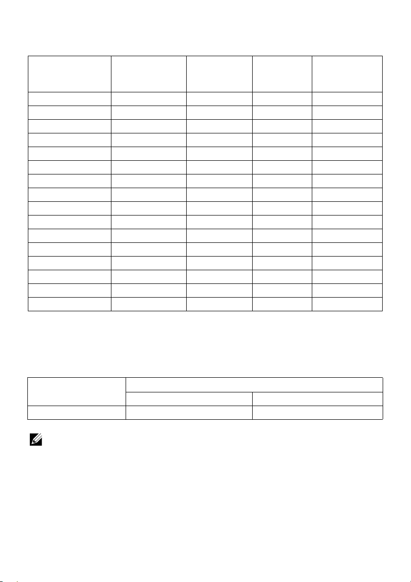
Preset Display Modes
Display Mode Horizontal
Frequency (kHz)
VESA, 640 x 400 31.47 70.09 25.18 -/+
VESA, 640 x 480 31.47 59.94 25.17 -/-
VESA, 640 x 480 37.50 75.00 31.5 -/-
VESA, 720 x 400 31.47 70.08 28.32 -/+
VESA, 800 x 600 37.88 60.32 40 +/+
VESA, 800 x 600 46.88 75.00 49.5 +/+
VESA, 1024 x 768 48.36 60.00 65 -/-
VESA, 1024 x 768 60.02 75.03 78.75 +/+
VESA, 1152 x 864 67.50 75.00 108 +/+
VESA, 1280 x 800 - R 49.31 59.91 71 +/-
VESA, 1280 x 1024 63.98 60.02 108 +/+
VESA, 1280 x 1024 79.98 75.03 135 +/+
VESA, 1600 x 1200 75.00 60.00 162 +/+
VESA, 1920 x 1080 67.50 60.00 148.5 +/+
VESA, 2560 x 1440 88.79 59.95 241.5 +/-
VESA, 3440 x 1440* 88.82 60.00 319.75 +/-
Vertical
Frequency
(Hz)
Pixel Clock
(MHz)
Sync Polarity
(Horizontal/
Vertical)
* Requires a graphics card that supports HDMI 2.0.
Multi-Stream Transport (MST) Modes
MST Source
Monitor
3440 x 1
40 at 60Hz 1 2
4
NOTE: The default for Multi
monitor for DP Multi-Stream Transport (MST) function
14 | About Your Monitor
Maximum number of external monitor can be supported
3440 x 1440 at 60Hz 1920 x 1080 at 60Hz
-Stream Transport mode is DP1.2. See
Connecting the
for details.
Page 15
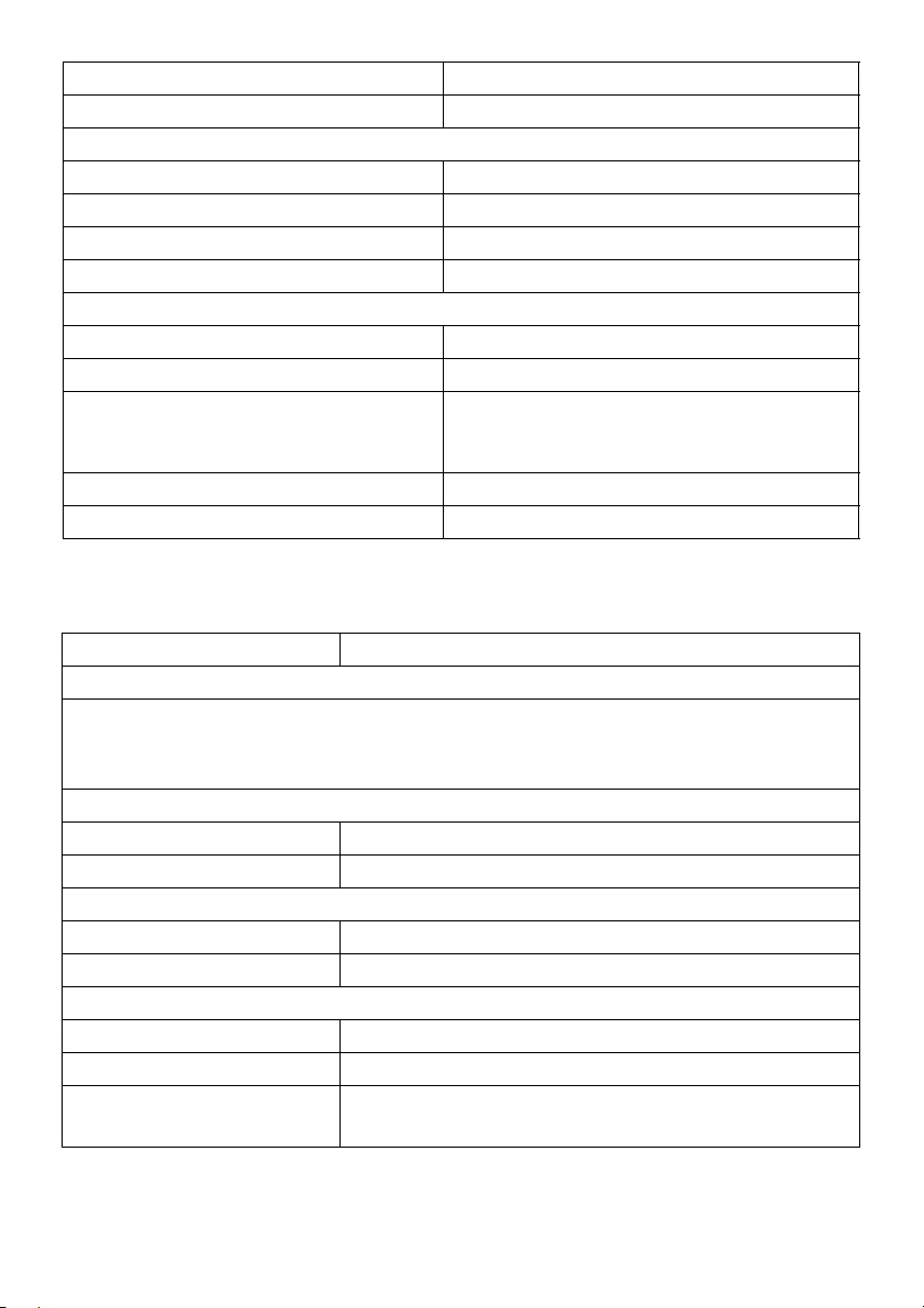
Electrical Specifications
Model U3417W
Video input signals HDMI 2.0*/DP 1.2**, 600 mV for each differential line,
100 ohm input impedance per differential pair.
AC input voltage/frequency/
current
Inrush current • 120 V: 40 A (Max.) at 0 °C (cold start)
100 VAC to 240 VAC / 50 Hz or 60 Hz
(typical)
• 220 V: 80 A (Max.) at 0 °C (cold start)
+ 3 Hz / 1.5 A
Support HDMI 2.0 optional specification, include HDMI
* Not
Audio Return Channel (ARC), standard for 3D format and resolutions, and standard for 4K
digital cinema resolution.
** Support DP1.2 specification, include HBR2, MST and DP audio.
Ethernet Channel (HEC),
Speaker Specifications
Model U3417W
Speaker 2 x 9.0 W
Frequency Response 100 Hz - 20 kHz
Impedance 8 ohm
Physical Characteristics
Model U3417W
Signal cable type • Digital: detachable, HDMI,
• Digital: detachable, Mini-DP to DP, 20
pins
• Universal Serial Bus: detachable, USB, 9
pins
Dimens
Height (extended) 532.0 mm (20.94 inches)
Height (compressed) 417.0 mm (16.42 inches)
Width 813.6 mm (32.03 inches)
Depth 226.4 mm (8.91 inches)
Dimensions (without stand)
Height 363.7 mm (14.32 inches)
ions (with stand)
19 pins
About Your Monitor | 15
Page 16
dth 813.6 mm (32.03 inches)
Wi
Depth 58.4 mm (2.30 inches)
Stand dimensions
Height (extended) 419.1 mm (16.50 inches)
Height (compressed) 382.6 mm (15.06 inches)
Width 342.2 mm (13.47 inches)
Depth 226.4 mm (8.91 inches)
Weight
Weight with packaging 15.4 kg (33.94 lb)
Weight with stand assembly and cables 10.4 kg (22.92 lb)
Weight without stand assembly (For wall
erations -
mount or VESA mount consi
no cables)
Weight of stand assembly 2.3 kg (5.07 lb)
Front frame gloss 37%-57% gloss unit
d
7.7 kg (16.97 lb)
Environmental Characteristics
Model U3417W
Compliant Standards
• BFR/PVC-free (Halogen-free) excluding external cables.
• Meets NFPA
• Arsenic-Free glass and Mercury-Free for the panel only.
Temp er atur e
Operating 0 °C to
Non-operating -20 °C to 60 °C (-4 °F to 140 °F)
Humidity
Operating 10% to 80% (non-condensing)
Non-operating 5% to 90% (non-condensing)
Altitude
Operating 5,000 m (16,404 ft) (maximum)
Non-operating 12,192 m (40,000 ft) (maximum)
Thermal dissipation
99 leakage current requirements.
40 °C (32 °F to 104 °F)
• 443.58 BTU/hour (maximum)
• 170.61 BTU/hour (typical)
16 | About Your Monitor
Page 17
Power Management Modes
If you have VESA's DPM™ compliance display card or software installed in your PC, the
monitor can automatically reduce its power consumption when not in use. This is
referred to as Power Save Mode*. If the computer detects input from the keyboard,
mouse, or other input devices, the monitor automatically resumes functioning. The
following table shows the power consumption and signaling of this automatic power
saving feature.
VESA Modes Horizontal
Sync
Normal
operation
Active-off
mode
Switch off - - - Off Less than 0.5 W
Active Active Active White 130 W (maximum)**
Inactive Inactive Blanked White (glowing) Less than 0.5 W
* Zero power consumption in OFF mode can only be achieved by disconnecting the
main cable from the monitor.
** Maximum power consumption with max luminance, and USB active.
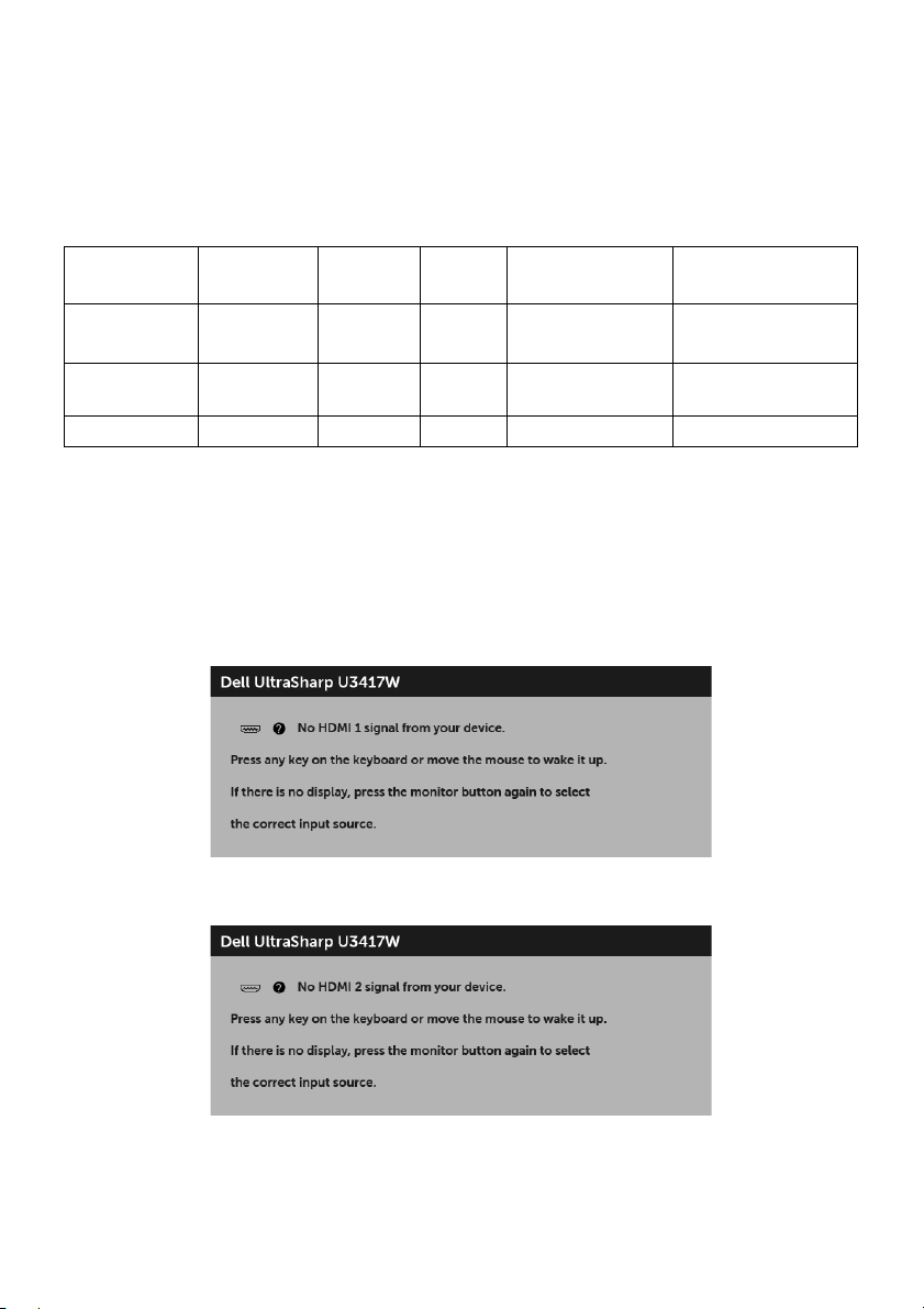
The OSD functions only in the normal operatio
the Active-off mode, one of the following messages will be displayed:
HDMI 1/HDMI 2/Mini DisplayPort/DP input
Vertical
Sync
Video Power
Indicator
Consumption
50 W (typical)
n mode. When any button is pressed in
Power
or
or
About Your Monitor | 17
Page 18
or
Activate the computer and the monitor to gain access to the OSD.
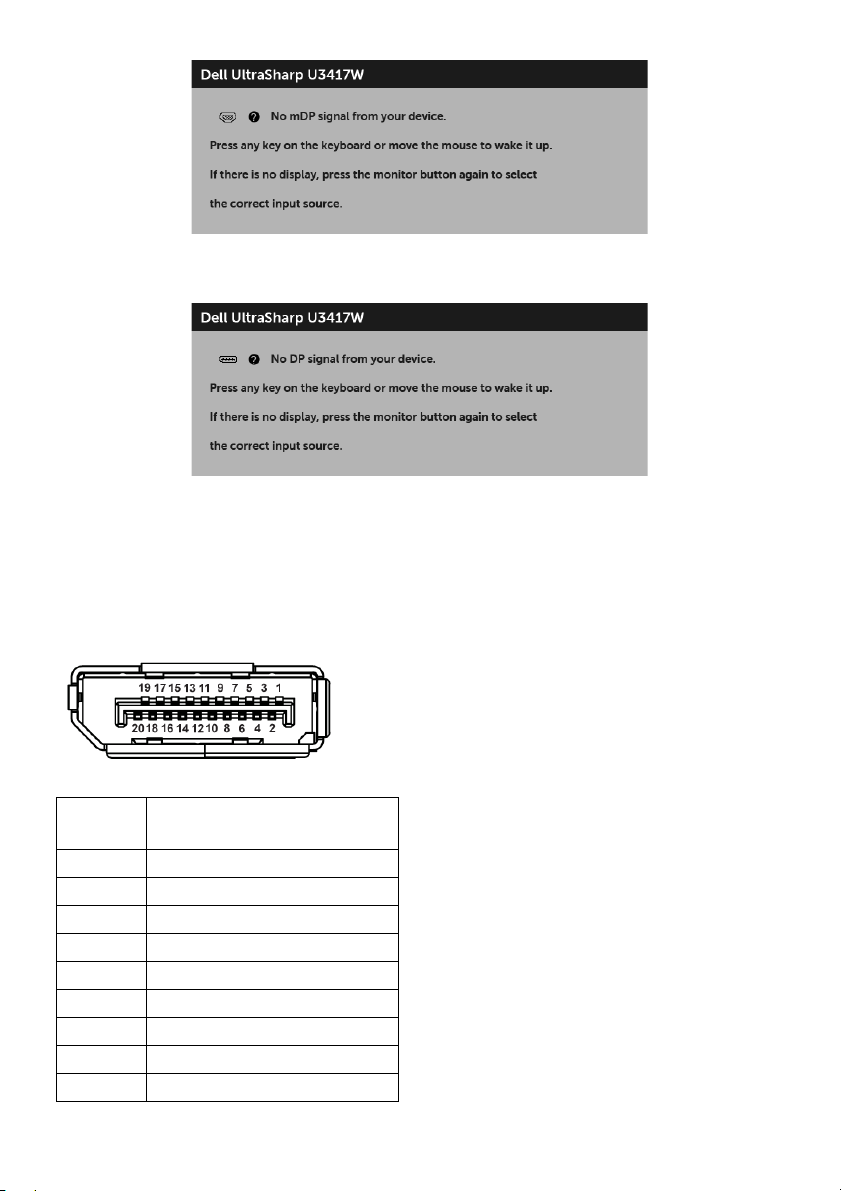
Pin Assignments
DisplayPort Connector
Pin
Number
1 ML0(p)
2 GND
3 ML0(n)
4 ML1(p)
5 GND
6 ML1(n)
7 ML2(p)
8 GND
9 ML2(n)
20-pin Side of the
Connected Signal Cable
18 | About Your Monitor
Page 19
10 ML3(p)
11 GND
12 ML3(n)
13 GND
14 GND
15 AUX(p)
16 GND
17 AUX(n)
18 GND
19 Re-PWR
20 +3.3 V DP_PWR
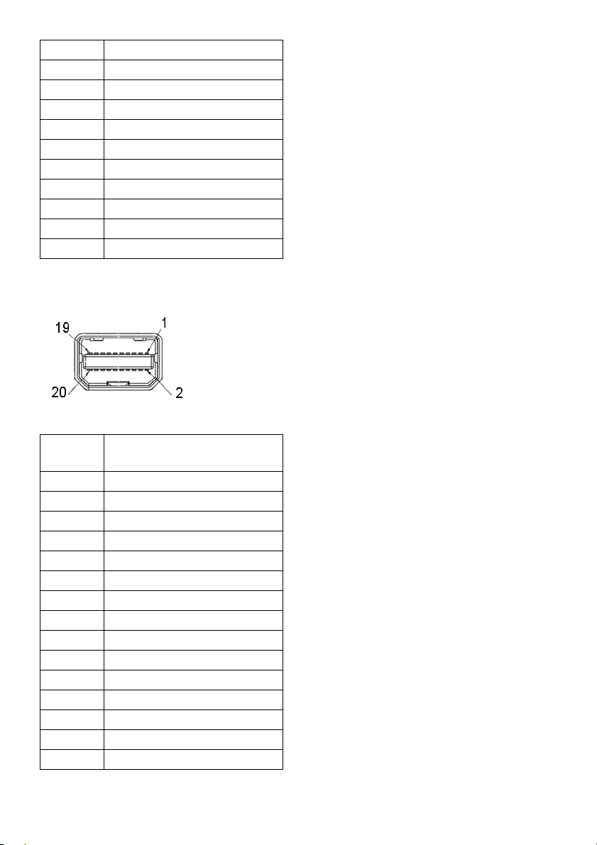
Mini DisplayPort Connector
Pin
Number
1 GND
2 Hot Plug Detect
3 ML3(n)
4 GND
5 ML3(n)
6 GND
7 GND
8 GND
9 ML2(n)
10 ML0(p)
11 ML2(p)
12 ML0(p)
13 GND
14 GND
15 ML1(n)
Connected Signal Cable
20-pin Side of the
About Your Monitor | 19
Page 20
16 AUX(p)
17 ML1(p)
18 AUX(n)
19 GND
20 +3.3 V DP_PWR
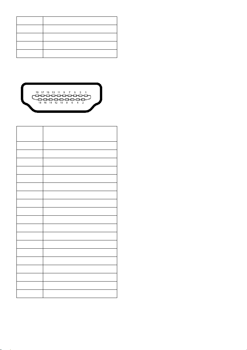
HDMI Connector
Pin
Number
1
2
3
4
5
6
7
8
9
10
11
12
13
14
15
16
17
18
19
19-pin Side of the
Connected Signal Cable
TMDS DATA 2+
TMDS DATA 2 SHIELD
TMDS DATA 2-
TMDS DATA 1+
TMDS DATA 1 SHIELD
TMDS DATA 1-
TMDS DATA 0+
TMDS DATA 0 SHIELD
TMDS DATA 0-
TMDS CLOCK+
TMDS CLOCK SHIELD
TMDS CLOCK-
CEC
Reserved (N.C. on device)
DDC CLOCK (SCL)
DDC DATA (SDA)
DDC/CEC Ground
+5V POWER
HOT PLUG DETECT
20 | About Your Monitor
Page 21

Plug and Play Capability
You can install the monitor in any Plug and Play-compatible system. The monitor
automatically provides the computer system with its Extended Display Identification Data
(EDID) using Display Data Channel (DDC) protocols so the system can configure itself
and optimize the monitor settings. Most monitor installations are automatic; you can
select different settings if desired. For more information about changing the monitor
settings, see
Operating the Monitor
.
Universal Serial Bus (USB) Interface
This section gives you information about the USB ports that are available on the monitor.
NOTE: This monitor is Super-Speed USB 3.0 compatible.
Transfer Speed Data Rate Power Consumption*
Super-speed 5 Gbps 4.5 W (Max, each port)
High speed 480 Mbps 4.5 W (Max, each port)
Full speed 12 Mbps 4.5 W (Max, each port)
* Up to 2A on USB downstream port (port with
compliance devices or normal USB devices.
USB Upstream Connector
Pin Number 9-pin Side of the Connector
1 VCC
2 D-
3 D+
4 GND
5 SSTX-
6 SSTX+
lightning icon) with BC1.2
About Your Monitor | 21
Page 22

7 GND
8 SSRX-
9 SSRX+
USB Downstream Connector
Pin Number 9-pin Side of the Connector
1
2 D-
3 D+
4 GND
5 SSRX-
6 SSRX+
7 GND
8 SSTX-
9 SSTX+
VCC
USB Ports
• 2 x USB 3.0 upstream - bottom
• 2 x USB 3.0 downstream - bottom
• 2 x USB 3.0 downstream - side
• Power Charging Port-
the port with lightning icon; supports fast current
charging capability if the device is BC1.2 compatible.
i
NOTE: USB 3.0 funct
NOTE: The moni
onality requires a USB 3.0-capable computer.
tor's USB interface works only when the monitor is On or in the
power save mode. If you turn Off the monitor and then turn it On, the attached
peripherals may take a few seconds to resume normal functionality.
LCD Monitor Quality and Pixel Policy
During the LCD Monitor manufacturing process, it is not uncommon for one or more
pixels to become fixed in an unchanging state which are hard to see and do not affect
the display quality or usability. For more information on Dell Monitor Quality and Pixel
22 | About Your Monitor
Page 23

Policy, see Dell Support site at: http://www.dell.com/support/monitors.
Maintenance Guidelines
Cleaning Your Monitor
CAUTION: Read and follow the
WARNING: Before cleaning the monitor, unplug the monitor power cable from
the electrical outlet.
For best practices, follow the instructions in the list below while
handling your monitor:
• To clean your anti-static screen, lightly dampen a soft, clean cloth with water. If
possible, use a special screen-cleaning tissue or solution suitable for the antistatic coating. Do not use benzene, thinner, ammonia, abrasive cleaners, or
compressed air.
• Use a lightly-dampened, warm cloth to clean the monitor. Avoid using
detergent of any kind as some detergents leave a milky film on the monitor.
• If you notice white powder when you unpack your monitor, wipe it off with a
cloth.
• Handle your monitor with care as a darker-colored monitor may get scratched
and show white scuff marks more than a lighter-colored monitor.
• To help maintain the best image quality on your monitor, use a dynamically
changing screen saver and turn Off your monitor when not in use.
Safety Instructions
before cleaning the monitor.
unpacking, cleaning, or
About Your Monitor | 23
Page 24

Setting Up the Monitor
Attaching the Stand
NOTE: The stand is detached when the monitor is shipped from the factory.
NOTE: This is applicable for a monitor with a
bought, please refer to the respective stand setup guide for the set up instructions.
CAUTION: Do not remove the monitor fro
the stand.
To attach the monitor stand:
1 Follow the instructions on the flaps of carton to remove the stand from the top
cus
hion that secures it.
2 Insert the stand base blocks fully into the stand slot.
3 Lift the screw handle and turn the screw clockwise.
4 After fully tightening the screw, fold the screw handle flat within the recess.
stand. When any other stand is
m the packaging box before attaching
24 | Setting Up the Monitor
Page 25

5 Lift the cover, as shown, to expose the VESA area for stand assembly.
6 Attach the stand assembly
a Fit the two tabs on the upper part of the stand to the groove on the back of the
monitor.
b Press the stand down till it snaps into place.
to the monitor.
Setting Up the Monitor | 25
Page 26

7 Place the monitor upright.
a Slide one hand in the cutout area on the bottom cushion and use the other
hand to hold the stand.
b Lift the monitor carefully to prevent it from slipping or falling.
CAUTION: Do not press on the panel screen when lifting the monitor.
8 Re
move the cover from the monitor.
26 | Setting Up the Monitor
Page 27

Connecting Your Monitor
WARNING: Before you begin any of the procedures in this section, follow the
Safety Instructions
NOTE: Do not connect a
To connect your monitor to the computer:
1 T
urn Off your computer and di
Connect the DP/Mini-DP to DP/HDMI cable from your
Connecting the HDMI cable
Connecting the black DisplayPort (Mini-DP to DP) cable
.
ll cables to the computer at the same time.
sconnect the power cable.
monitor to the computer.
Setting Up the Monitor | 27
Page 28

Connecting the black DisplayPort (DP to DP) cable
Connecting the monitor for DP Multi-Stream Transport (MST)
function
NOTE: U3417W supports the DP MST feature. To make use of this feature, your PC
Graphics Card must be certified to DP1.2 with MST option.
The default out of factory setting in the U3417W is DP1.2.
To enable MST connection, please use only DP cable as
certified cable) and perform the below steps:
28 | Setting Up the Monitor
provided in box (or other DP1.2
Page 29
A) Monitor is able to show content
1 Use OSD button to
2 Go to MST selection.
3 Select On or Off accordingly.
B) Monitor fails to show any content (blank screen)
1 Press any button other than the power button to activate the Input Sou
Use the and buttons to highlight DP or mDP.
navigate to Display.
rce menu.
2 Press and hold the button for approximately 8 seconds.
3 The DisplayPort con
figuration message will appear.
Setting Up the Monitor | 29
Page 30

4 Use the and buttons to highlight Enable or Disable and press the
button to confirm selection.
Repeat the above steps to change the DP
format
setting if necessary.
CAUTION: The graphics are used for the purpose of illustra
of the computer may vary.
tion only. Appearance
Connecting the USB 3.0 cable
NOTE: To prevent data damage or loss, before changing USB upstream ports, make
sure that NO USB storage devices are in use by the computer connected to the
monitor’s USB upstream port.
After you have completed connecting the Mini-DP to DP/DP/HDMI cable, follow the
procedures below to connect the USB 3.0 cable to the computer and complete your
monitor setup:
1 a. Connect one computer: connect the upstream USB 3.0 port (cable supplied) to
an appropriate USB 3.0 port on your computer.
b. Connect two computers*: connect the upstr
USB 3.0 ports on the two computers. Then use the OSD menu to select between
the two USB upstream sources and input sources. See
2 Connect the
3 Plug the power cables for your computer(s)
USB 3.0 peripherals to the downstream USB 3.0 ports on the monitor.
eam USB 3.0 ports to appropriate
USB Select Switch
and monitor into a nearby outlet.
.
a. Connect one computer
30 | Setting Up the Monitor
Page 31

b. Connect two computers
* When connecting two computers to the monitor, the monitor's USB downstream ports
for the keyboard and mouse can be assigned to different input signals from the two
computers by changing the USB Selection settings from the OSD menu. (See
Selection
4 Turn On the monitor and the computer(s).
5 Use the cable
for details).
If your monitor displays
image, see
Universal Serial Bus (USB) Specific Problems
slot on the monitor stand to organize the cables.
an image, installation is complete. If it does not display an
.
USB
Organizing Your Cables
After attaching all necessary cables to your monitor and computer, (See
Monitor
for cable attachment,) organize all cables as shown above.
Setting Up the Monitor | 31
Connecting Your
Page 32

Removing the Monitor Stand
NOTE: To prevent the curved LCD screen from being scratched and damaged
while removing the stand, ensure that the monitor is placed on a soft, clean foam.
Direct contact with hard objects might cause damage to the curved monitor.
NOTE: This is applicable for a monitor with a stand. When any other stand is
bought, please refer to the respective stand setup guide for the set-up instructions
.
To remove the stand:
1 Place the moni
2 Press and hold the stand release button.
3 Lift the stand up and away from the monitor.
tor on a soft cloth or cushion.
Wall Mounting (Optional)
(Screw dimension: M4 x 10 mm).
Refer to the instructions that come with the VESA-compatible wall mounting kit.
1 Place the moni
2 Remove the stand.
32 | Setting Up the Monitor
tor panel on a soft cloth or cushion on a stable, flat table.
Page 33

3 Use a Phillips crosshead screwdriver to remove the four screws securing the plastic
cover.
4 Attach
5 Mount
the mounting bracket from the wall mounting kit to the monitor.
the monitor on the wall by following the instructions that comes with the
wall mounting kit.
NOTE: For use on
bearing capacity of 30.6 kg.
ly with UL-listed wall mount bracket with minimum weight/load
Setting Up the Monitor | 33
Page 34

Operating the Monitor
Power On the Monitor
Press the button to turn On the monitor.
Using the Front Panel Controls
Use the control buttons on the front of the monitor to adjust the characteristics of the
image being displayed. As you use these buttons to adjust the controls, an OSD shows
the numeric values of the characteristics as they change.
34 | Operating the Monitor
Page 35

The following table describes the front panel buttons:
Front Panel Button Description
1
Use this button to choose from a list of preset color modes.
Shortcut key/
Preset Modes
2
Use this button to adjust the volume. Minimum is ‘0’ (-).
Maximum is ‘100’ (+).
Shortcut key/
Volume
3
Menu
4
Use the MENU button to launch the On-Screen Display
(OSD) and select the OSD Menu. See Accessing the Menu
System.
Use this button to go back to the main menu or exit the OSD
main menu.
Exit
5
Power
(with power light
Use the Power button to turn the monitor On and Off.
The white light indicates the monitor is On and fu
functional. A glowing white light indicates the power save
mode.
indicator)
lly
Front Panel Button
Use the buttons on the front of the monitor to adjust the image settings.
Front Panel Button Description
1
Up
Use the Up button to adjust (increase ranges) items in the OSD menu.
Operating the Monitor | 35
Page 36

2
Down
3
OK
4
Back
Use the Down button to adjust (decrease ranges) items in the OSD
menu.
Use the OK button to confirm your selection.
Use the Back button to go back to the previous menu.
Using the On-Screen Display (OSD) Menu
Accessing the Menu System
NOTE: If you change the settings and then either proceed to another menu or exit
the OSD menu, the monitor automatically saves those changes. The changes are
also saved if you change the settings and then wait for the OSD menu to disappear.
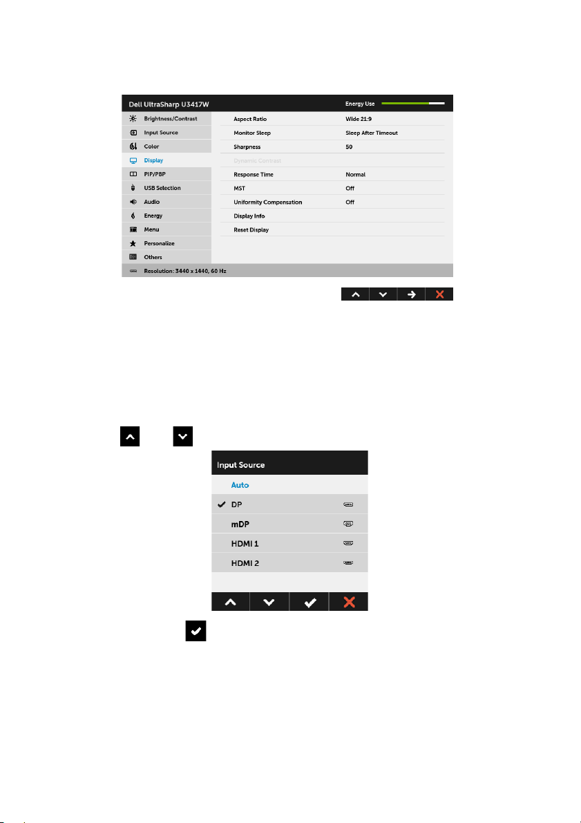
1 Press the button to launch the OSD menu and display the main menu.
Main Menu for digital (HDMI) input
or
36 | Operating the Monitor
Page 37

Main Menu for digital (mDP) input
or
Main Menu for digital (DP) input
2 Press the and buttons to move between the setting options. As you move
from one icon to another, the option name is highlighted. See the following table
for a complete list of all the options available for the monitor.
3 Press the button once to activate the highlighted option.
4 Press and button to select the desired parameter.
5 Press to enter the slide bar and then use the and buttons, according
to the indicators on the menu, to make your changes.
6 Select the button to return to the main menu.
Operating the Monitor | 37
Page 38

Icon Menu and
Submenus
Brightness/
Contrast
Des
cription
Use this menu to activate Brightness/Contrast adjustment.
Brightness
Contrast
Brightness adjusts the luminance of the backlight.
Press the
button to decrease the brightness (min. 0 / max. 100).
button to increase the brightness and press the
NOTE: Manual adjustment of Brightness is disabled when Dynamic
Contrast is switched On.
Adjust the Brightness first, and then adjust the Contrast only if further
adjustment is necessary.
Press the
button to decrease the contrast (min. 0 / max. 100).
The Co
darkness and lightness on the monitor screen.
button to increase the contrast and press the
ntrast function
adjusts the degree of difference between
38 | Operating the Monitor
Page 39
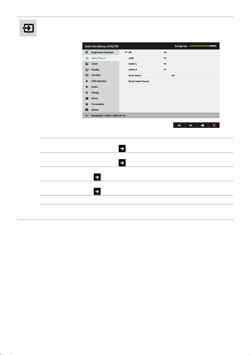
Input Source
Use the Input Source menu to select between the different video
signals that may be connected to your monitor.
DP
mDP
HDMI 1
HDMI 2
Auto Select
Reset Input
Source
Select the DP input when you are using the DisplayPort (DP)
connector. Press
Select the mDP input when you are using the Mini DisplayPort (mDP)
connector. Press
Select the HDMI 1 input when you are using the HDMI 1 connector.
Press
Select the HDMI 2 input when you are using the HDMI 2 connector.
Press
Turning on the function allows you to scan for available input sources.
Reset your monitor input settings to the factory settings.
to select the HDMI 1 input source.
to select the HDMI 2 input source.
to select the DisplayPort input source.
to select the Mini DisplayPort input source.
Operating the Monitor | 39
Page 40

Color
Use Color to adjust the color setting mode.
40 | Operating the Monitor
Page 41

Preset Modes
When you select Preset Modes, you can choose Standard,
ComfortView, Multimedia, Movie, Game, Color Temp.,or Custom
Color from the list.
•Standard: Loads the
default preset mode.
•ComfortView: Decreases t
the screen to make viewing more comfortable for your eyes.
•Multimedia: Loa
•Movie: Loads color sett
•Game: Load
• Color Temp.: A
5700K, 6500K, 7500K, 9300K, and 10000K.
• Custom Color: Allows you to
settings.
s color settings ideal for most gaming applications.
monitor's default color settings. This is the
he level of the blue light emitted from
ds color settings ideal for multimedia applications.
ings ideal for movies.
llows users to select the color temperature: 5000K,
manually adjust the 6-axis color
Press the
and create your own preset color mode.
and buttons to adjust the 6-axis colors values
Operating the Monitor | 41
Page 42

Input Color
Format
Allows you to set the video input mode to:
RGB: Select this option if your monitor is connected to a computer (or
DVD
player) using the HDMI cable (or DisplayPort cable).
YPbPr: S
by
Or if the DVD color output setting is not RGB.
elect this option if your monitor is connected to a DVD player
YPbPr using HDMI cable (or DisplayPort cable).
42 | Operating the Monitor
Page 43

Gamma
Allows you to set the Gamma to 2.2 or 1.8.
Hue
Saturation
Reset Color
This feature can shift the color of the video image to green or purple.
This is used to adjust the desired flesh tone color. Use
adjust the hue from '0' to '100'.
Use
Use
to increase the green shade of the video image.
to increase the purple shade of the video image.
or to
NOTE: Hue adjustment is available only when you select Movie or
Game preset mode.
This feature can adjust the color saturation of the video image. Use
or to adjust the saturation from '0' to '100'.
Use
to increase the colorful appearance of the video image.
to increase the monochrome appearance of the video image.
Use
NOTE: Saturation adjustment is available only when you select Movie
or Game preset mode.
Reset your monitor color settings to the factory settings.
Operating the Monitor | 43
Page 44

Display
Use Display to adjust image.
Aspect Ratio
Monitor Sleep
Sharpness
Adjusts the image ratio to Wide 21:9, Auto Resize, 4:3, or 1:1.
Allows you to let the monitor turn off automatically or stay on when
your computer goes into sleep mode. When Sleep After Timeout is
selected, the monitor goes to sleep as the system sleeps; when Never
is selected, you may prevent the screen from going off as the system
sleeps for speedy display recovery from PC wake up.
This feature can make the image look sharper or softer. Use or
to adjust the sharpness from '0' to '100'.
44 | Operating the Monitor
Page 45

Dynamic
Contrast
Response
Time
MST
Uniformity
Compensation
Display Info
Reset Display
Allows you to increase the level of contrast to provide sharper and
more detailed image quality.
Press the
button to select the Dynamic Contrast "On" or "Off".
NOTE: Dynamic Contrast provides higher contrast if you select
Game or Movie preset mode.
Allows you to set the Response Time to Normal or Fast.
Press to select the MST "On" or "Off".
To use the DP MST (Daisy Chain) feature, turn on MST.
Select screen uniformity compensation settings. Calibrated is factory
calibrated setting by default. Uniformity Compensation adjusts
different areas of the screen with respect to the center to achieve
uniform brightness and color over the entire screen. For optimal
screen performance, Brightness and Contrast for some preset modes
(Standard, Color Temp.) will be disabled when Uniformity
Compensation is turned On.
NOTE: User is advised to use factory default brightness setting when
Uniformity Compensation is turned on. For other brightness level
setting, the uniformity performance may deviate from the data shown
on the Factory Calibration Report.
Displays the monitor's current settings.
Select this option to restore default display settings.
Operating the Monitor | 45
Page 46

PIP/PBP
X
X
X
X
Sub-Window
Main Window
DP
mDP
DP
mDP
HDMI 1
HDMI 1
HDMI 2
HDMI 2
This function brings up a window displaying image from another input
source.
46 | Operating the Monitor
X
X
X
NOTE: The images under PBP will be displayed at the center of the
screen, not full screen.
NOTE: When you use the PIP/PBP feature, the DP MST (Daisy Chain)
function is disabled.
X
Page 47

PIP/PBP Mode
PBP Fill
PBP Aspect Ratio
PIP LargePIP Small
Adjusts the PIP/PBP (Picture in Picture/Picture by Picture) mode to PIP
Small, PIP Large, PBP Aspect Ratio, or PBP Fill. You can disable this
feature by selecting Off.
PIP/PBP (Sub)
PIP Location
USB Select
Switch
Video Swap
Contrast (Sub)
I
II
I
Select between the different video signals that may be connected to
your monitor for the PIP/PBP sub-window.
Select PIP sub-window position.
Use
Bottom-Right, or
Select to switch between the USB upstream sources in PIP/PBP mode.
Select to swap videos between main window and sub-window in PIP/
PBP mode.
Adjust the contrast level of the picture in PIP/PBP Mode.
Press the
button to decrease the contrast.
or to browse and to select Top-Left, Top -R ig ht ,
button to increase the contrast and press the
II
Bottom-Left.
I
I
II
II
Operating the Monitor | 47
Page 48

USB Selection
USB 1
USB 2
Select the USB upstream signals from the list: DP, mDP, HDMI 1, and
HDMI 2, thus the monitor's USB downstream port (eg. keyboard and
mouse) can be used by the current input signals when connecting a
computer to either one of the upstream ports.
The display and USB upstream ports connection can be changed by
the
selecting
When you use only one upstream port, the connected upstream port
c
tive.
is a
input source function.
NOTE: To prevent data damage or loss, before changing USB
upstream ports, make sure that NO USB storage devices are in use by
the computer connected to the monitor’s USB upstream port.
Press to Indicate the input signal for USB 1.
Press to Indicate the input signal for USB 2.
48 | Operating the Monitor
Page 49

Audio
Volume
Audio Source
Allows you to set the volume level of speakers.
Use
Allows you to set the audio source from the main window or the subwindow.
or to adjust the volume level from '0' to '100'.
Speaker Allows you to enable or disable the speaker function.
Reset Audio
Select this option to restore default audio settings.
Operating the Monitor | 49
Page 50

Energy
Power Button
LED
USB
Reset Energy
Allows you to set the power LED indicator On or Off to save energy.
Allows you to enable or disable USB function during monitor standby
mode.
NOTE: USB ON/OFF under standby mode is only available when the
USB upstream cable is unplugged. This option will be greyed out when
the USB upstream cable plugs in.
Select this option to restore default Energy settings.
50 | Operating the Monitor
Page 51
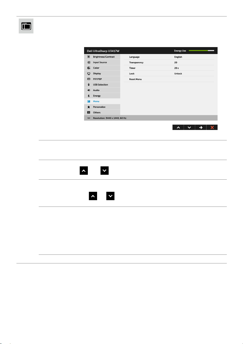
Menu
Select this option to adjust the settings of the OSD, such as, the
languages of the OSD, the amount of time the menu remains on
screen, and so on.
Language
Transparency
Time r
Lock
Reset Menu
Language options set the OSD display to one of the eight languages
(English, Spanish, French, German, Brazilian Portuguese, Russian,
Simplified Chinese or Japanese).
Select this option to change the menu transparency by pressing the
and buttons (Minimum: 0 ~ Maximum: 100).
OSD Hold Time: sets the length of time the OSD will remain active
after the last time you pressed a button.
Use
to 60 seconds.
Controls user access to adjustments. When Lock is selected, no user
adjustments are allowed. All buttons are locked.
or to adjust the slider in 1 second increments, from 5
NOTE:
Unlock function– Only hard unlock (press and hold the button beside
the power button for 6 seconds).
Lock function – Either
(press and hold the button beside the power button for 6 seconds).
Reset all OSD settings to the factory preset values.
soft lock (through the OSD menu) or hard lock
Operating the Monitor | 51
Page 52

Personalize
Others
Users can choose a feature from Preset Modes, Brightness/Contrast,
Input Source, Aspect Ratio, Volume, PIP/PBP Mode, USB Select
Switch, or Video Swap and set it as a shortcut key.
52 | Operating the Monitor
Page 53

DDC/CI
DDC/CI (Display Data Channel/Command Interface) allows your
monitor parameters (brightness, color balance, and etc.) to be
adjustable via the software on your computer.
ure
You can disable this feat
Enable this feature for best user experience and optimum
performance o
f your monitor.
by selecting Disable.
LCD
Conditioning
Firmware
Reset Others
Factory Reset
Helps reduce minor cases of image retention. Depending on the
degree of image retention, the program may take some time to run.
You can enable this feature by selecting Enable.
Displays the current firmware version.
Reset all settings under the Others menu to the factory preset values.
Reset all settings to the factory preset values.
Operating the Monitor | 53
Page 54

NOTE: This monitor has
to compensate for LED aging.
a built-in feature to automatically calibrate the brightness
OSD Warning Messages
When the Dynamic Contrast feature is enabled (in these preset modes: Game or Movie),
the manual brightness adjustment is disabled.
When the monitor does not support a particular resolution mode, you will see the
following message:
This means that the monitor cannot synchronize with the signal that it is receiving from
the computer. See
ranges addressable by this monitor. Recommended mode is 3440 x 1440.
You will see the following message before the DDC/CI function is disabled:
Monitor Specifications
for the Horizontal and Vertical frequency
54 | Operating the Monitor
Page 55

When the monitor enters the Power Save mode, the following message appears:
or
or
Activate the computer and wake up the monitor to gain access to the
If you press any button other than the power button, one of the
appear depending on the selected input:
HDMI/Mini DisplayPort/DP input
or
following messages will
OSD
.
Operating the Monitor | 55
Page 56
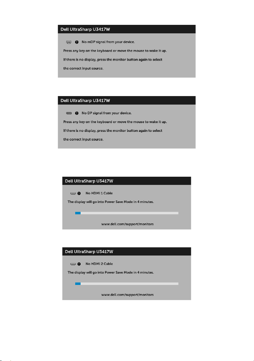
or
or
If either HDMI, Mini DisplayPort, or DP input is selected and the corresponding cable is
not connected, a floating dialog box as shown below appears.
or
or
56 | Operating the Monitor
Page 57

or
See
Troubleshooting
for more information.
Setting the Maximum Resolution
To set the maximum resolution for the monitor:
In Windows
1 For Windows
2 Right-click on the desktop and click Screen Resolution.
3 Click the Dropdown list of the Screen Resolution and select 3440 x 1440.
4 Click OK.
In Windows
1 Right-click on the desktop and click Display settings.
2 Click Advanc
3 Click the dropdown list of Resolution and select 3440 x 1440.
4 Click Apply.
If you do not see 3440 x 1440 as an option, you may nee
Depending on your computer, complete one of the following procedures:
If you have a Dell desktop or portable computer:
• Go to http://www.dell.com/support, enter your service tag, and download the
®
7, Windows® 8, and Windows® 8.1:
®
8 and Windows® 8.1 only, select the Desktop tile to switch to classic
desktop.
®
10:
ed display settings.
latest driver for your graphics card.
d to update your graphics driver.
Operating the Monitor | 57
Page 58

If you are using a non-Dell computer (po
• Go to the support site for your computer
• Go to your graphics card website and download the latest
rtable or desktop):
and download the latest graphic drivers.
graphic drivers.
Using the Tilt, Swivel, and Vertical Extension
NOTE: This is applicable for a monitor with a stand. When any other stand is
bought, please refer to the respective stand setup guide for set up instructions.
Tilt, Swivel
With the stand attached to the monitor, you can tilt and swivel the monitor for the most
comfortable viewing angle.
NOTE: The stand is detached when the monitor is shipped from the factory.
58 | Operating the Monitor
Page 59

Vertical Extension
NOTE: The stand extends vertically up to 115 mm. The figure below illustrates how
to extend the stand vertically.
Dual-Monitor Setup
The recommended dual-monitor setup:
Landscape (side by side)
Operating the Monitor | 59
Page 60

Troubl es ho ot ing
WARNING: Before you begin any of the procedures in this section, follow the
Safety Instructions
Self-Test
Your monitor provides a self-test feature that allows you to check whether your monitor
is functioning properly. If your monitor and computer are properly connected but the
monitor screen remains dark, run the monitor self-test by performing the following
steps:
1 Turn off both your computer and the monitor.
2 Unplug the video cable from the back of the computer. To ensure proper Self-Test
operation, remove all digital cables from the back of computer.
3 Turn on the monitor.
The floating dialog box should appear on-screen (
monitor cannot sense a video signal and is working correctly. While in self-test mode, the
power LED remains white. Also, depending upon the selected input, one of the dialogs
shown below will continuously scroll through the screen.
.
against a black background), if the
or
or
60 | Troubleshooting
Page 61

or
4 This box also appears during normal system operation, if the video cable becomes
disconnected or damaged.
5 Turn Off your monitor and reconnect the video cable; then turn On both your
computer
If your monitor screen remains blank after you use the previous procedure, check your
video controller and computer, because your monitor is functioning properly.
and the monitor.
Built-in Diagnostics
Your monitor has a built-in diagnostic tool that helps you determine if the screen
abnormality you are experiencing is an inherent problem with your monitor, or with your
computer and video card.
NOTE: You can run the built-in diagnostics only when the video cable is unplugged
and the monitor is in self-test mode.
To run the built-in diagnostics:
Troubleshooting | 61
Page 62

1 Ensur
2 Unp
e that the screen is clean (no dust particles on the surface of the screen).
lug the video cable(s) from the back of the computer or monitor. The monitor
then goes into the self-test mode.
3 Press and hold Button 1 on the front panel for 5 seconds. A gray screen appears.
4 Carefully inspect the screen for abnormalities.
5 Pr
ess Button 1 on the front panel again. The color of the screen changes to red.
6 Inspect the display
for any abnormalities.
7 Repeat steps 5 and 6 to inspect the display in green, blue, black, white and text
screens.
The test is complete when the text screen appe
ars. To exit, press Button 1 again.
If you do not detect any screen abnormalities upon using the built-in diagnostic tool, the
monitor is functioning properly. Check the video card and computer.
Common Problems
The following table contains general information about common monitor problems you
might encounter and the possible solutions:
Common
Sy
mptoms
No Video/Power
LED off
No Video/Power
LED on
Poor Focus Picture is fuzzy,
Shaky/Jittery
deo
Vi
What You
Experience
No picture • Ensure that the video cable connecting the monitor and the
No picture or no
brightness
urry, or
bl
ghosting
Wavy picture or
fine movement
Possible Solutions
computer is properly connected and secure.
• V
erify that the power outlet is functioning properly using
any other electrical equipment.
• En
sure that the power button is pressed fully.
• Ensure t
• Increase bri
• P
• Check
• Run t
• Ensure t
• Eliminat
• R
• Change
• Reset the monitor to factory settings.
• Check envir
• R
hat the correct input source is selected in the
menu.
Source
ghtness & contrast controls via OSD.
erform monitor self-test feature check.
for bent or broken pins in the video cable connector.
he built-in diagnostics.
hat the correct input source is selected in the
menu.
Source
e video extension cables.
eset the monitor to factory settings.
the video resolution to the correct aspect ratio.
onmental factors.
elocate the monitor and test in another room.
Input
Input
62 | Troubleshooting
Page 63

Missing Pixels LCD screen has
Stuck-on Pixels LCD screen has
Brightness
Pro
blems
Geometric
istortion
D
Horizontal/
rtical Lines
Ve
Synchronization
blems
Pro
Safety Related
Issues
Intermittent
blems
Pro
Missing Color Picture missing
Wrong Color Picture color not
spots
br
ight spots
Picture too dim
or too bright
Screen not
centered
ectly
corr
Screen has one
or more lines
Screen is
scrambled or
appears torn
Visible signs of
e or sparks
smok
Monitor
malfunctions on
& off
color
od
go
• Cycle power On-Off.
ixel that is permanently Off is a natural defect that can
• P
occur in LCD technology.
more information on Dell Monitor Quality and Pixel
• For
Policy, see Dell Support site at: http://www.dell.com/
support/monitors.
• Cycle power On-Off.
ixel that is permanently off is a natural defect that can
• P
occur in LCD technology.
more information on Dell Monitor Quality and Pixel
• For
Policy, see Dell Support site at: http://www.dell.com/
support/monitors.
• Reset the monitor to factory settings.
brightness & contrast controls via OSD.
• Adjust
• Reset the monitor to factory settings.
• Adjust
horizontal & vertical controls via OSD.
• Reset the monitor to factory settings.
erform monitor self-test feature check and determine if
• P
these lines are also in self-test mode.
• Check
• Run t
• R
• P
• Check
• Re
• Do not perform any troubleshooting steps.
• Cont
• Ensure that the video cable connecting the monitor to the
• R
• P
• P
• En
• Check
• Change the settings of the Preset Modes in the Color menu
• Adju
• Change
• Run t
for bent or broken pins in the video cable connector.
he built-in diagnostics.
eset the monitor to factory settings.
erform monitor self-test feature check to determine if the
scrambled screen appears in self-test mode.
for bent or broken pins in the video cable connector.
start the computer in the safe mode.
act Dell immediately.
computer is connected properly and is secure.
eset the monitor to factory settings.
erform monitor self-test feature check to determine if the
intermittent problem occurs in self-test mode.
erform monitor self-test feature check.
sure that the video cable connecting the monitor to the
computer is connected properly and is secure.
for bent or broken pins in the video cable connector.
OSD depending on the application.
st R/G/B value under Custom Color in Color menu
OSD.
the Input Color Format to PC RGB or YPbPr in the
Color menu OSD.
he built-in diagnostics.
Troubleshooting | 63
Page 64

ge left on
a
ention
Faint shadow
om the static
fr
image displayed
appears on the
screen
the Power Management feature to turn off the monitor
• Use
at all times when not in use (for more information, see
Power Management Modes
• Alternatively, use a dynamically changing screensaver.
Image ret
from a static
im
the monitor for
a long period of
time
Product Specific Problems
).
Specific
Symptoms
Screen image is
too small
Cannot
adjust
the
monitor
with the
buttons on the
front panel
No Input Signal
en user
wh
controls are
pressed
icture
The p
does not fill the
entire screen
What You
Experience
Image is
centered on
en, but does
scre
not fill entire
viewing area
OSD does not
pear on the
ap
screen
No picture, the
ght is white
LED li
The picture
not fill the
can
height or width
of the screen
Possible Solutions
• Check the Aspect Ratio setting in the Display menu OSD.
• Reset the monitor to factory settings.
urn Off the monitor, unplug the power cord, plug it back,
• T
and then turn On the monitor.
• Check whether the OSD menu is locked. If yes, press and
the button beside the Power button for 6 seconds to
hold
Lock
unlock (for more information, see
• Check the signal source. Ensure the computer is not in the
power saving mode by moving the mouse or pressing any
key on the keyboard.
• Check
• Reset the computer or video player.
• D
• Run the built-in diagnostics.
whether the signal cable is plugged in properly. Re-
plu
g the signal cable if necessary.
ue to different video formats (aspect ratio) of DVDs, the
monitor may display in full screen.
).
64 | Troubleshooting
Page 65

Universal Serial Bus (USB) Specific Problems
Specific
Symptoms
USB interface is
not working
High Speed
US
.0
B 3
interface is
slow
W
ireless mouse
ot working
is n
or lagging
What You
Experience
USB peripherals
are not working
High Speed USB
0 peripherals
3.
working slowly or
not working at all
Do not respond
or responds
slowly
• Check that your monitor is turned On.
• Reconnect the upstream cab
• Reconnect the USB pe
• Switch Off and then turn On the monitor again.
• Reboot the computer.
• Some USB devices like external portable HDD require higher
electric cu
computer system.
onnect one upstream USB cable when using two
• Disc
upst
ream connections.
• Check
• Some computers have USB 3.0, USB 2.0, and USB 1.1 ports.
• Reconnect the upstream cab
• Reconnect the USB pe
• Reboot the computer.
• I
• Position your wireless USB re
• Use a USB-extender cable to position the wireless USB
that your computer is USB 3.0-capable.
that the correct USB port is used.
Ensure
ncrease the distance between the USB 3.0 peripherals and
the wireless USB receiver.
the wireless mouse.
eceiver as far away as possible from the USB 3.0 port.
r
Speakers Specific Problems
Possible Solutions
le to your computer.
ripherals (downstream connector).
rrent; connect the device directly to the
le to your computer.
ripherals (downstream connector).
ceiver as close as possible to
Specific
Symptoms
No sound
coming from
the speakers
What You
Experience
Cannot hear any
sound
Possible Solutions
• Turn Off the monitor, unplug the monitor power cord,
replug it, and then turn On the monitor.
• Check
• U
• Reset the monitor to factory settings.
the audio cable connection is connected correctly
o the computer Audio Line Out port.
t
nplug the audio cable from the Audio Line Out port.
Troubleshooting | 65
Page 66

Appendix
WARNING: Safety Instructions
WARNING: Use of controls, adjustments, or procedures other than those
specified in this documentation may result in exposure to shock, electrical
hazards, and/or mechanical hazards.
For information on safety instructions, see the Safety
Information (SERI).
FCC Notices (U.S. Only) and Other Regulatory Information
For FCC notices and other regulatory information, see the regulatory compliance
website located at www.dell.com/regulatory_compliance.
Contact Dell
For customers in the United States, call 800-WWW-DELL (800-999-3355).
, Environmental, and Regulatory
NOTE: If you
information on your purchase invoice, packing slip, bill, or Dell product catalog.
Dell provides several online and telephone-based support and service options.
Availability var
your area.
• Online technical assistance ─ www.dell.com/support/monitors
• Contacting Dell ─ www.dell.com/contactdell
do not have an active Internet connection, you can find contact
ies by country and product, and some services may not be available in
66 | Appendix
 Loading...