

Dell SwitchX M4001T, SwitchX M4001Q, SwitchX M4001F User Manual

www.mellanox.com
Third party information brought
to you courtesy of Dell.
SwitchX® InfiniBand Blade Switch I/O Module
for PowerEdge M-Series User Manual
PN: M4001F, M4001T, M4001Q
Rev 1.2

Mellanox Technologies
350 Oakmead Parkway Suite 100
Sunnyvale, CA 94085
U.S.A.
www.mellanox.com
Tel: (408) 970-3400
Fax: (408) 970-3403
Mellanox Technologies, Ltd.
Beit Mellanox
PO Box 586 Yokneam 20692
Israel
Tel: +972 (0)4 909 7200 ; +972
(0)74 723 7200
Fax: +972 (0)4 959 3245
© Copyright 2012.
Mellanox, Mellanox logo, BridgeX, ConnectX, CORE-Direct, InfiniBridge, InfiniHost, InfiniScale, PhyX, SwitchX, Virtual Protocol
Interconnect and Voltaire are registered trademarks of Mellanox Technologies, Ltd. FabricIT, MLNX-OS, Unbreakable-Link, UFM and
Unified Fabric Manager are trademarks of Mellanox Technologies, Ltd.
All other trademarks are property of their respective owners.
InfiniBand Blade Switch I/O Module for PowerEdge M-Series
Document Number: 3513
Rev 1.2
Mellanox Technologies
2
NOTE:
THIS HARDWARE, SOFTWARE OR TEST SUITE PRODUCT (“PRODUCT(S)”) AND ITS RELATED DOCUMENT ATION ARE PROVIDED BY MELLANOX TECHNOLOGIES “AS-IS” WITH ALL FAULTS OF ANY KIND AND SOLEL Y FOR THE PURPOSE OF
AIDING THE CUSTOMER IN TESTING APPLICATIONS THAT USE THE PRODUCTS IN DESIGNATED SOLUTIONS. THE CUSTOMER'S MANUF ACTURING TEST ENVIRONMENT HAS NOT MET THE STANDARDS SET BY MELLANOX TECHNOLOGIES
TO FULLY QUALIFY THE PRODUCTO(S) AND/OR THE SYSTEM USING IT. THEREFORE, MELLANOX TECHNOLOGIES CANNOT AND DOES NOT GUARANTEE OR WARRANT THAT THE PRODUCTS WILL OPERATE WITH THE HIGHEST QUALITY.
ANY EXPRESS OR IMPLIED WARRANTIES, INCLUDING, BUT NOT LIMITED TO, THE IMPLIED WARRANTIES OF MER
CHANT ABILITY, FITNESS FOR A PARTICULAR PURPOSE AND NONINFRINGEMENT ARE DISCLAIMED. IN NO EVENT
SHALL MELLANOX BE LIABLE TO CUSTOMER OR ANY THIRD PARTIES FOR ANY DIRECT, INDIRECT, SPECIAL, EXEMPLARY, OR CONSEQUENTIAL DAMAGES OF ANY KIND (INCLUDING, BUT NOT LIMITED TO, PAYMENT FOR PROCUREMENT OF SUBSTITUTE GOODS OR SERVICES; LOSS OF USE, DATA, OR PROFITS; OR BUSINESS INTERRUPTION)
HOWEVER CAUSED AND ON ANY THEORY OF LIABILITY, WHETHER IN CONTRACT, STRICT LIABILITY, OR TORT
(INCLUDING NEGLIGENCE OR OTHERWISE) ARISING IN ANY WA Y FROM THE USE OF THE PRODUCT(S) AND RELATED
DOCUMENT ATION EVEN IF ADVISED OF THE POSSIBILITY OF SUCH DAMAGE.

InfiniBand Blade Switch I/O Module for PowerEdge M-Series Rev 1.2
Mellanox Technologies
3
Contents
Contents 3
Revision History 4
About this Manual 5
Chapter 1 Overview 7
1.1 InfiniBand Connectors 8
1.2 Switch Status Lights 9
1.3 I2C Interface RJ-45 Connector 10
Chapter 2 Installation and Basic Operation 11
2.1 Installation Safety Warnings 11
2.2 Mechanical Installation 13
2.2.1 Removing an Old Switch From the Chassis 13
2.2.2 Removing an I/O Module Blank From the Chassis 14
2.2.3 Installing the Mellanox M4001[F, T, Q] Switch Into the Dell Chassis 14
2.3 Power Connections and Initial Power On 14
2.4 InfiniBand Cable Installation 14
2.4.1 Supported Approved Cables 15
Chapter 3 Cluster Management and Firmware 16
3.1 Network Management and Clustering Software 16
3.2 Updating Firmware 16
3.2.1 Instructions for Reprogramming Over the InfiniBand Network 16
Chapter 4 Troubleshooting 17
Appendix A Specifications 18
Appendix B EMC Certification Statements 20
Appendix C QSFP Interface 22
Appendix D Avertissements de sécurité d’installation 24
Appendix E Installation - Sicherheitshinweise 26
Rev 1.2
Mellanox Technologies
4
Revision History
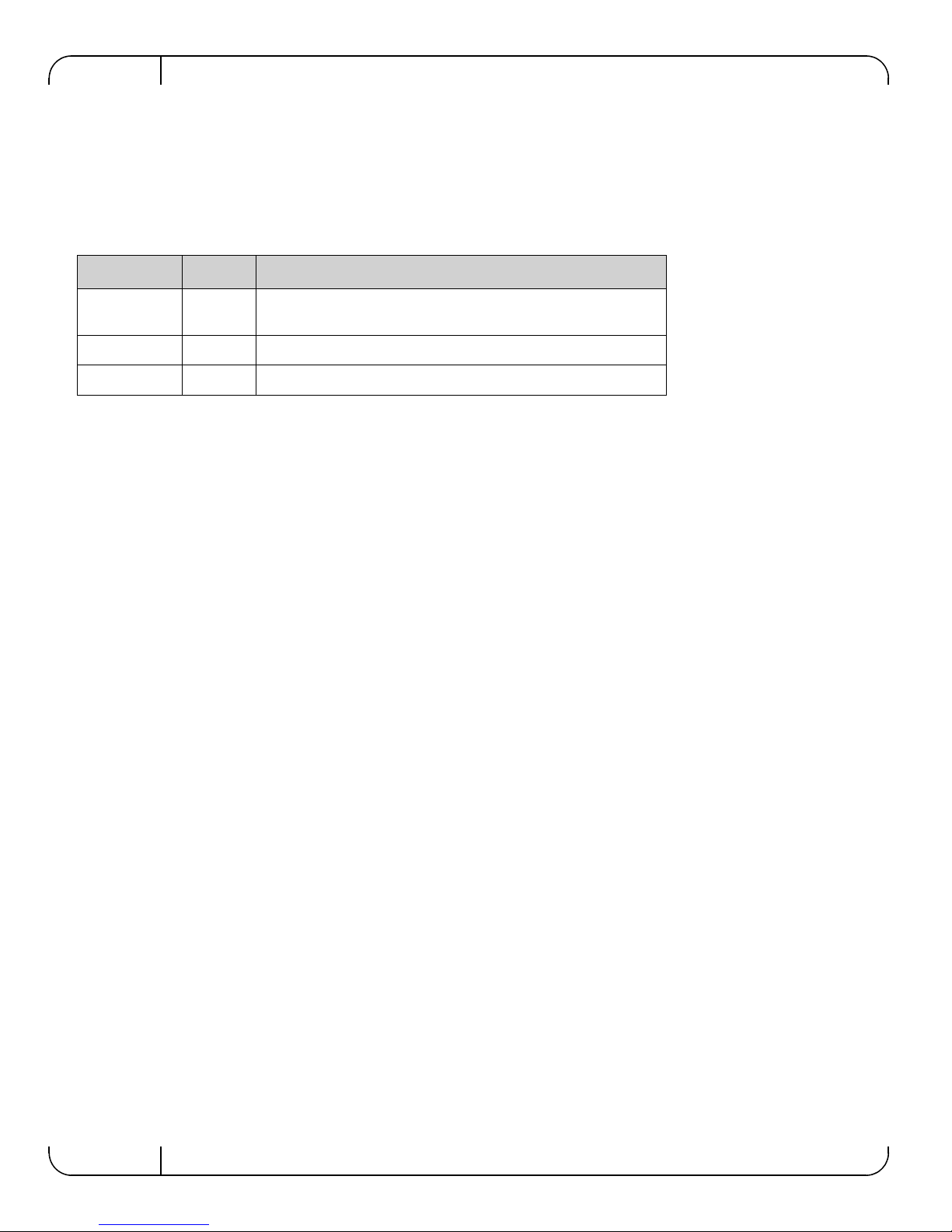
Table 1 - Revision History Table
Date Revision Description
June 2012 1.2 Added graphics to section 2.4
Added section2.4.1
May 2012 1.1 Added M4001T switch
November 2011 1.0 Initial release

InfiniBand Blade Switch I/O Module for PowerEdge M-Series Rev 1.2
Mellanox Technologies
5
About this Manual
This manual describes the installation and basic use of the SwitchX® M4001F(FDR) 56 Gb/s,
M4001T(FDR10) 40Gb/s and the M4001Q(QDR) 40 Gb/s InfiniBan d blade switch I/O modules
for the PowerEdge M-Series chassis.
Intended Audience
This manual is intended for users and system administrators responsible for installing and setting
up the switch platforms listed above.
The manual assumes familiarity with the InfiniBand® Architecture Specification.
Related Documentation
The documentation set accompanying the Mellanox M4001[F, T, Q] includes the following:
Online Resources
• Mellanox Technologies Web pages: http://www.mellanox.com
• Dell Support Web pages: http://support.dell.com
Conventions
Throughout this manual, the names M4001F, M4001T, and M4001Q and the terms switch, I/O
module, and IOM are used to describe the M4001F FDR, M4001T F DR10, an d the M 4001Q QDR
InfiniBand blade switch I/O modules, unless explicitly indicated otherwise.
Table 2 - Reference Documents
InfiniBand Architecture Specification
Volume 1 Release 1.2.1 and V olume 2
release 1.2.1
InfiniBand architecture specification descriptions
Mellanox Firmware Tools (MFT)
User’s Manual
Document # 2329
The MFT (Mellanox Firmware Tools) package is a set of firmware tools. The
manual supplied with this package provides an overview of the firmware its
installation and replacement. The MFT can be downloaded with its documenta
tion at:
http://www.mellanox.com > Downloads > Firmware Tools.
Rev 1.2
Mellanox Technologies
6
The following pictures are used throughout this document to indicate information that is important
to the user.
This symbol makes recommendations to the user.
This symbol indicates information that is helpful to the user.
This symbol indicates a situation that can potentially cause damage to hardware or
software.
BEWARE! This symbol indicates a situation that can potentially cause personal injury
or damage to hardware or software.

InfiniBand Blade Switch I/O Module for PowerEdge M-Series Rev 1.2
Mellanox Technologies
7
1 Overview
The SwitchX® InfiniBand blade switch I/O module for the PowerEdge M-Series chassis provides
a high bandwidth, low latency fabric for Enterprise Data Centers (EDC), High-Performance Com
-
puting (HPC), and Embedded environments. Based on the 5th generation InfiniBand switch device
(1
st
Generation SwitchX). This I/O module (IOM) delivers up to 56Gb/s at FDR speed and
40 Gb/s at FDR10 and QDR speed full bisectional bandwidth per po rt. When used in conjunction
with ConnectX®-3 InfiniBand dual port Mezzanine I/O cards, clustered data bases, parallelized
applications and transactional services applications these switches will achieve significant perfor
-
mance improvements resulting in reduced completion time and lower cost per operation.
The I/O module comes pre-installed with all necessary firmware, and configured for standard
operation within an InfiniBand fabric, and only requires an InfiniBand compliant Subnet Manager
running from one of the hosts. All that is required for normal operation is to follow the usual pre
cautions for installation and connection from the switch to the HCAs or other switches. Once connected, the Subnet Management software automatically configures the switch and begins utilizing
the switch.
It is recommended that Mellanox OpenFabrics software package be installed on all nodes connected to the M4001[F, T, Q]. The software package provides a subnet manager and network management tools as well as connectivity software for servers and storage, and is available on the
Mellanox web site. See Chapter 3 for more information.
Basic installation, hot-swapping components and hardware maintenance is covered in “Installation
and Basic Operation” on page 11.
The M4001F, M4001T, and M4001Q switches have a Hot Swap controller and a PSOC Management IC.
OverviewRev 1.2
Mellanox Technologies
8
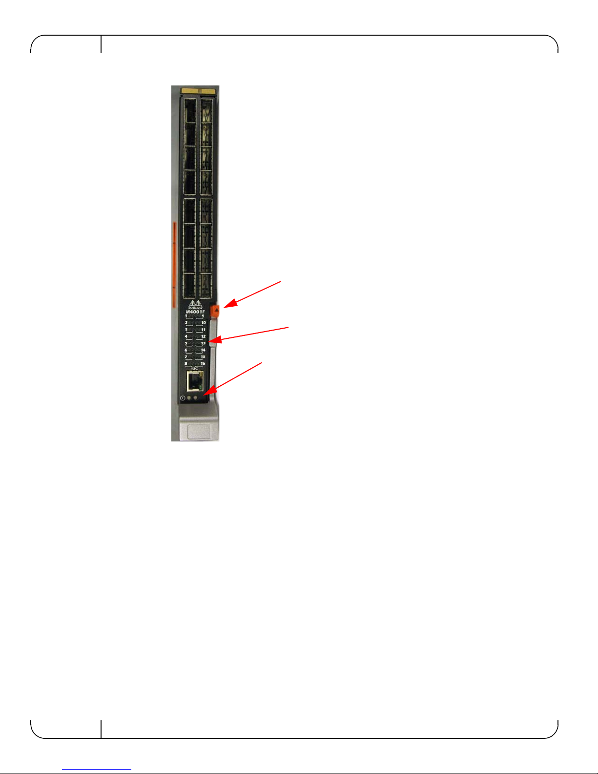
Figure 1: Switch Front Panel and Locking Mechanism
1.1 InfiniBand Connectors
This switch has 16 QSFP connectors through the front panel. The remaining 16 interfaces are
through the Midplane Connector out of the back of the switch.
Figure 1 shows the front 16 ports.
Each of the InfiniBand ports has two LEDs located between the connectors and the I2C interface.
The green LED, when lit, indicates that a valid physical connection to the other system (switch or
HCA port) exists. See
Figure 2,“Physical and Logical Link Indication LEDs” for more details.
Locking Mechanism
Switch Status Lights
Port LEDs
InfiniBand Blade Switch I/O Module for PowerEdge M-Series Rev 1.2
Mellanox Technologies
9
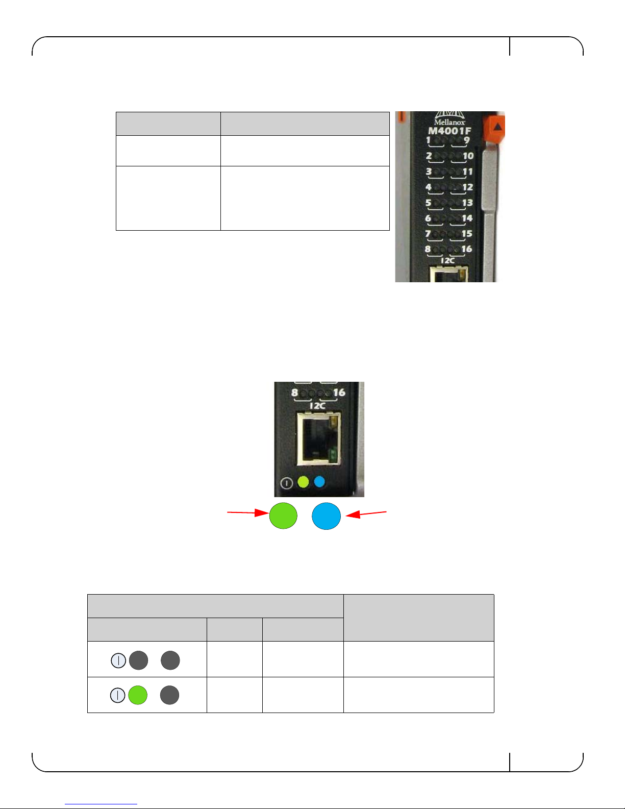
Figure 2: Physical and Logical Link Indication LEDs
1.2 Switch Status Lights
The switch Status lights indicate whether the switch is receiving power from the chassis, and the
state of the switch.
Figure 3: Indicator LEDs
Table 3 - IOM states and LED configu r ations:
LED
Switch Status
Indication Green Status
OFF OFF OFF
ON OFF Boot in Progress
Switch not ready
LED Name Connection Status
Physical Link - Green Off – No Physical Link
ON – Physical Link
Data Activity - Yellow
Blinking – indicates Data Transfer
Constant on – indicates Link exists
with no Data Transfer taking place
Off with green LED lit – indicates that
the Subnet Manager may not be running
The IO Module is on and
ready when both the blue
and green LEDs are lit.
This LED can be blue or
amber. A fault is indicated
when the amber LED is
blinking. See Table 3.
 Loading...