

Dell SmartStep 200N, SmartStep 250N Replacement Manual

Contents
1 Removing and Replacing Parts
2 Before You Remove or Install Parts
Preparing to Work Inside the Computer . . . . . . . . . . . . . . 8
Recommended Tools . . . . . . . . . . . . . . . . . . . . . . . . 10
Computer Orientation
Screw Identification . . . . . . . . . . . . . . . . . . . . . . . . 11
. . . . . . . . . . . . . . . . . . . . . . . 11
3 System Components
4 Memory Module, Modem, and Optical Drive
Memory Module . . . . . . . . . . . . . . . . . . . . . . . . . . 22
Removing the Memory Module . . . . . . . . . . . . . . . . . 22
Modem
Optical Drive
. . . . . . . . . . . . . . . . . . . . . . . . . . . . . . . 26
. . . . . . . . . . . . . . . . . . . . . . . . . . . . 29
Installing an Optical Drive
. . . . . . . . . . . . . . . . . . . 30
5 Hard Drive
Removing the Hard Drive . . . . . . . . . . . . . . . . . . . . 32
Installing the Hard Drive
. . . . . . . . . . . . . . . . . . . . 34
Contents 1

6 Keybo ar d
Removing the Keyboard . . . . . . . . . . . . . . . . . . . . 36
Installing the Keyboard . . . . . . . . . . . . . . . . . . . . 39
7 Display Assembly and Display Latch
Display Assembly . . . . . . . . . . . . . . . . . . . . . . . . . 42
Display Bezel
Display Panel . . . . . . . . . . . . . . . . . . . . . . . . . . . 48
Display Latch
Removing the Display Latch
Installing the Display Latch
Removing the Display Hinges . . . . . . . . . . . . . . . . . . 51
Installing the Display Hinges
. . . . . . . . . . . . . . . . . . . . . . . . . . . 45
. . . . . . . . . . . . . . . . . . . . . . . . . . . 51
. . . . . . . . . . . . . . . . . . 51
. . . . . . . . . . . . . . . . . . 51
. . . . . . . . . . . . . . . . . . 51
8 Reserve Batter y and Palm Re st
Reserve Battery . . . . . . . . . . . . . . . . . . . . . . . . . . 54
Palm Rest . . . . . . . . . . . . . . . . . . . . . . . . . . . . . 56
9 Floppy Drive
10 Microprocessor Thermal-Cooling Assembly and
Microprocessor Module
Microprocessor Thermal-Cooling Assembly . . . . . . . . . . . . 66
Microprocessor Module
11 Speakers
Removing the Speakers . . . . . . . . . . . . . . . . . . . . 70
Installing the Speakers
2 Contents
. . . . . . . . . . . . . . . . . . . . . . 67
. . . . . . . . . . . . . . . . . . . . . 71

12 System Board
Removing the System Board . . . . . . . . . . . . . . . . . . 74
Installing the System Board . . . . . . . . . . . . . . . . . . 81
13 Optical Drive Latch and Battery Latch Assemblies
Removing the Optical Drive Latch and Battery Latch Assemblies 84
Installing the Optical Drive Latch and Battery Latch Assemblies
85
3 Contents

4 Contents

SECTION 1
Removing and
Replacing Parts
1

www.dell.com | support.dell.com
6 Removing and Replacing Parts

SECTION 2
Before You Remove or
Install Parts
2

www.dell.com | support.dell.com
Preparing to Work Inside the
Computer
CAUTION: Only a certified service technician should perform
repairs on your computer. Damage due to servicing that is not
authorized by Dell is not covered by your warranty. Read and
follow the safety instructions in the Dell
NOTICE: To avoid damaging the computer, perform the following steps before
you begin working inside the computer.
Ensure that the work surface is flat and clean to prevent scratching the
1
Owner’s Manual
computer cover.
2 Save any work in progress and exit all open programs.
3 Shut down the computer and turn off all attached devices.
.
HINT: Ensure that the
computer is off and not in
a power management
mode. If you cannot shut
down the computer using
the computer operating
system, press and hold the
power button for 4
seconds.
Disconnect the computer from the electrical outlet.
4
5 To avoid possible damage to the system board, wait 10 to 20 seconds
and then disconnect any attached devices.
6 Disconnect all other external cables from the computer.
7 Remove any installed PC Cards or blanks from the PC Card slot.
8 Close the display and turn the computer upside down on a flat work
surface.
NOTICE: To avoid damaging the system board, you must remove the battery
before you service the computer.
8 Before You Remove or Install Parts
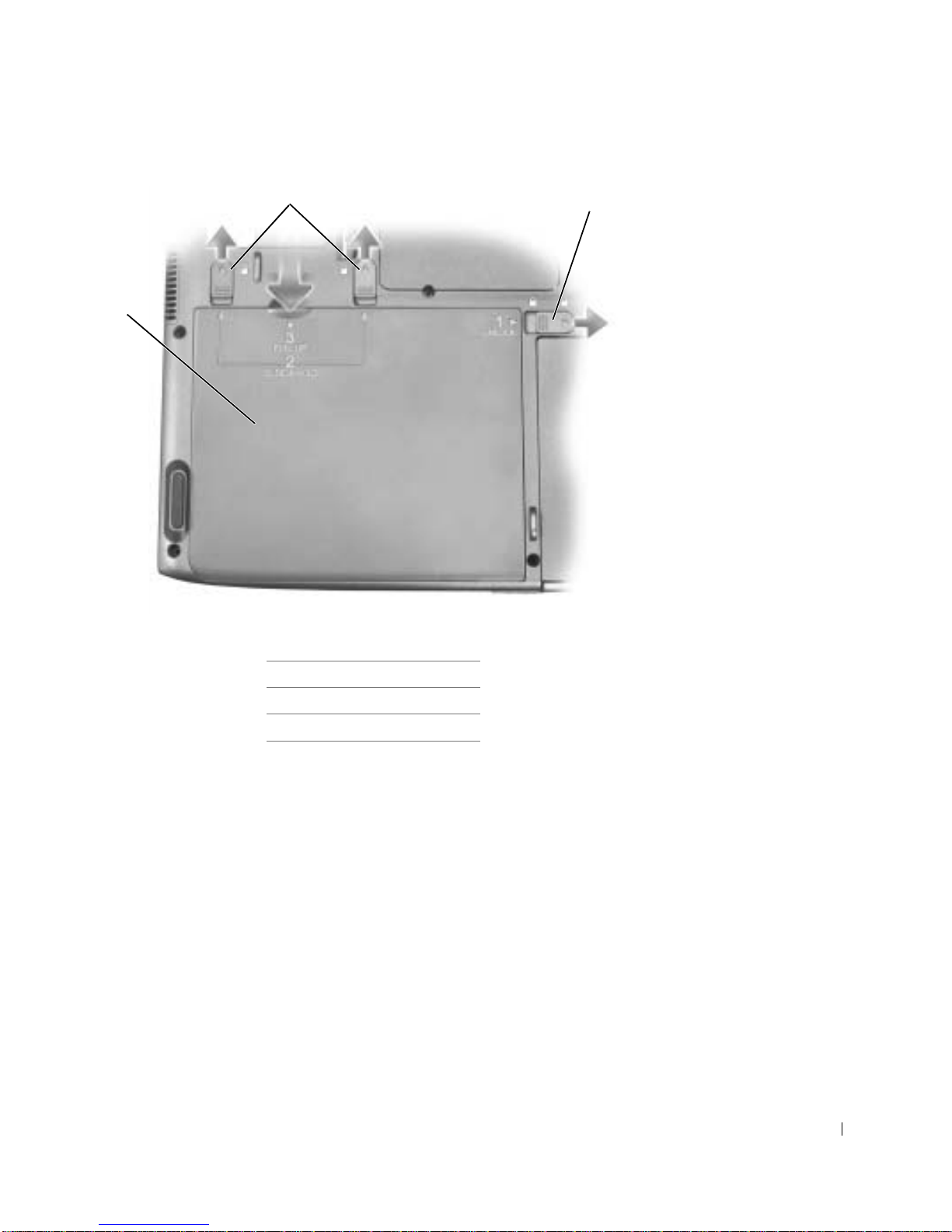
2
3
1
1 battery
2 battery latch release
3 battery lock
9 Remove the battery:
a Slide the battery lock to the unlock position.
b Slide the two battery latch releases toward the back of the
computer and hold them.
c Lift the battery up using the raised tab toward the front of the
computer.
d Remove the battery from the computer.
10 To dissipate any static electricity while you work, use a wrist grounding
strap or periodically touch an unpainted metal surface.
Before You Remove or Install Parts 9

11 Handle components and cards with care. Do not touch the
components or contacts on a card. Hold a card by its edges or by its
metal mounting bracket. Hold a component such as a microprocessor
by its edges, not by its pins.
Recommended Tools
The procedures in this document require the following tools:
• #1 magnetized Phillips screwdriver
• ¼-inch flat-blade screwdriver
www.dell.com | support.dell.com
•Nut driver
• Small plastic scribe
• Microprocessor extractor
• Flash BIOS program update floppy disk
10 Before You Remove or Install Parts
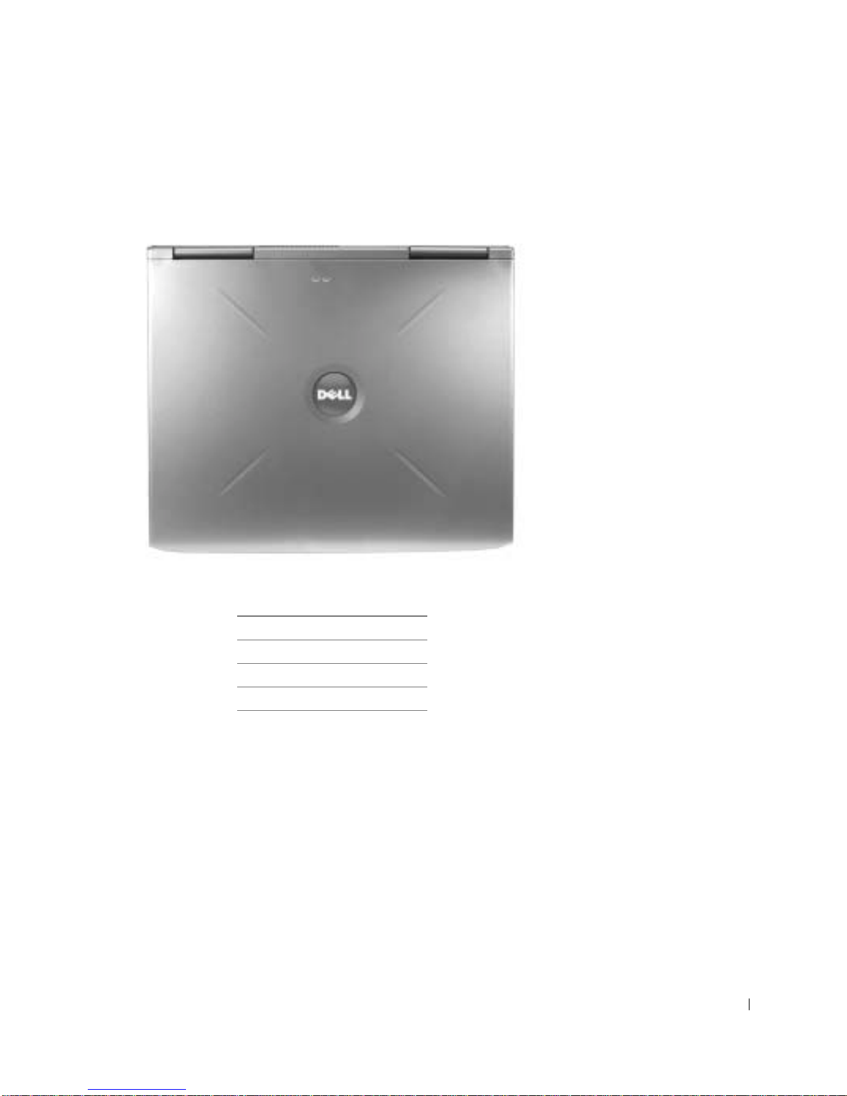
Computer Orientation
1
24
3
1 back
2 right
3 front
4 left
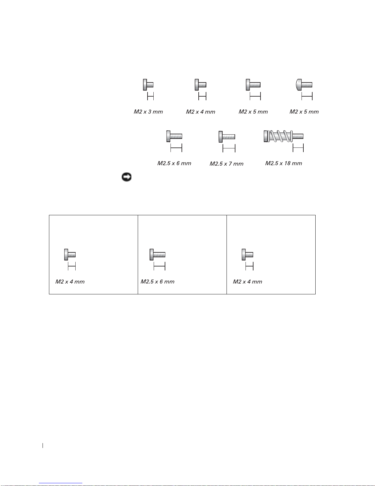
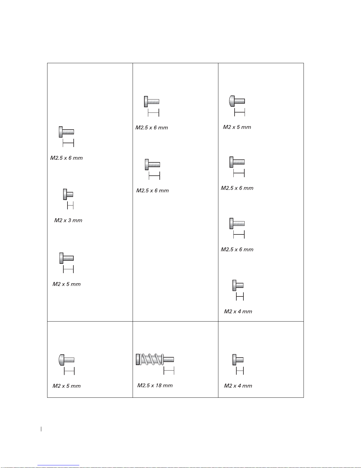
Screw Identification
When you are removing and installing components, print the following few
pages as a placemat to lay out and keep track of the component screws. The
placemat provides the number of screws and the sizes.
Before You Remove or Install Parts 11
www.dell.com | support.dell.com
NOTICE: When reinstalling a screw, you must use a screw of the correct
diameter and length. Ensure that the screw is properly aligned with its
corresponding hole, and avoid overtightening.
Modem to system board:
(2 each)
Hard drive:
(4 each)
Keyboard
(3 each)
12 Before You Remove or Install Parts
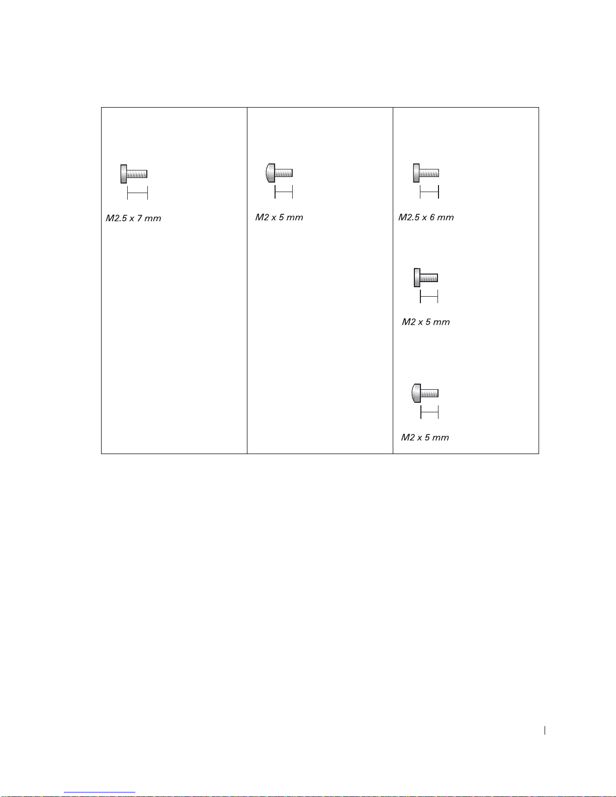
Display to bottom case:
Palm rest shield:
Display hinges:
(2 each)
(1 each)
(2 each)
(2 each)
(1 each)
Before You Remove or Install Parts 13
Display bezel:
Display inverter screw:
Palm rest to bottom case:
large screw bumpers (2 each)
small screw bumpers (2 each)
screw cover (1 each)
(5 each)
www.dell.com | support.dell.com
(2 each)
(2 each)
(1 each)
Display hinges screw:
(2 each)
(13 each)
(1 each)
Floppy drive to system board:
(1 each)
Thermal assembly to heat sink:
(4 each)
14 Before You Remove or Install Parts
(1 each)
Speaker to bottom case:
(2 each)
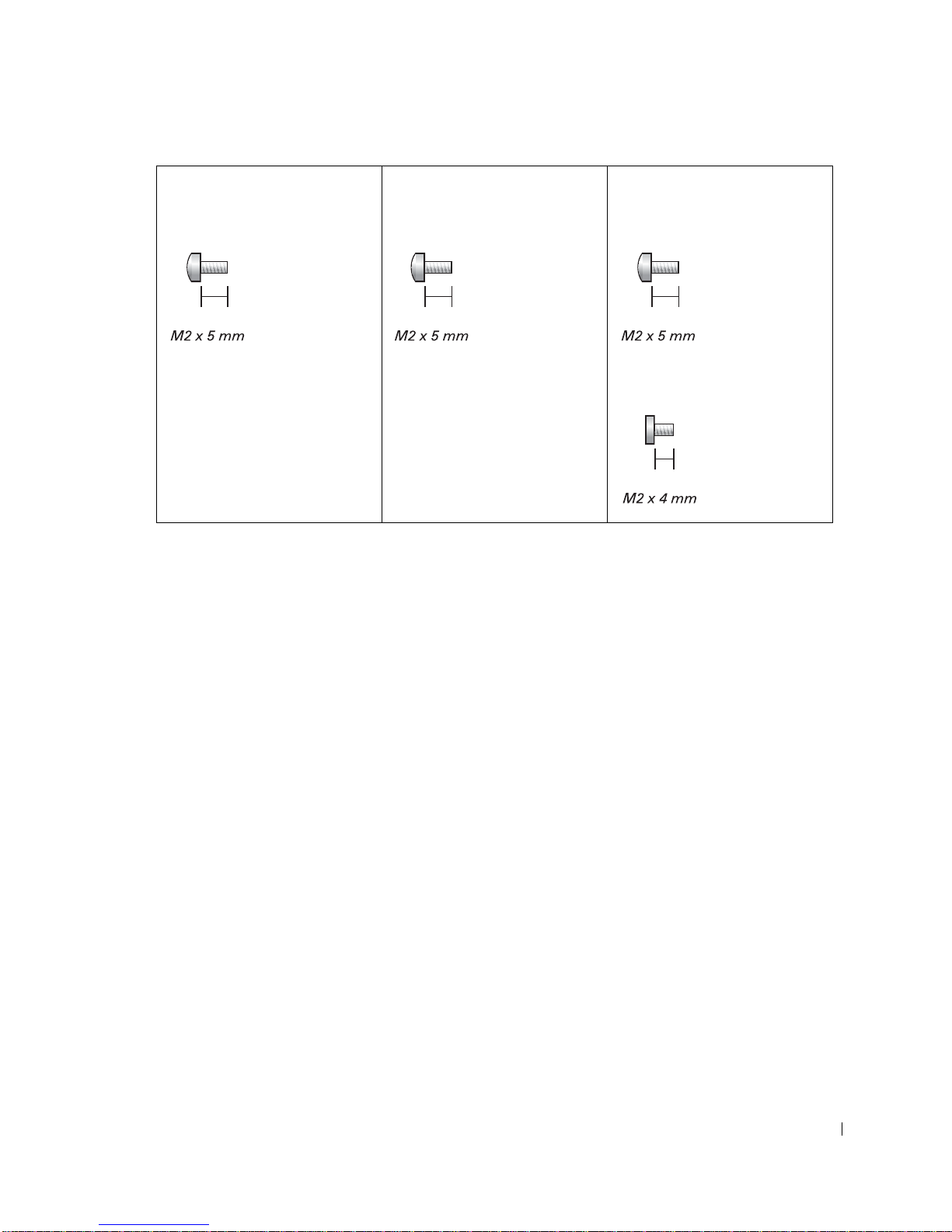
Video shield:
Motherboard shield:
System board to bottom case:
(4 each)
(2 each)
(3 each)
(1 each)
Before You Remove or Install Parts 15

www.dell.com | support.dell.com
16 Before You Remove or Install Parts

SECTION 3
System Components
3

www.dell.com | support.dell.com
NOTICE: Only a certified service technician should perform repairs on your
computer . Damage due to servicing that is not authorized by Dell is not covered
by your warranty.
NOTICE: Unless otherwise noted, each procedure in this document assumes
that a part can be replaced by performing the removal procedure in reverse
order.
18 System Components
1
2
3
22
21
20
19
18
17
16
4
5
6
7
8
9
10
11
15
14
12
13
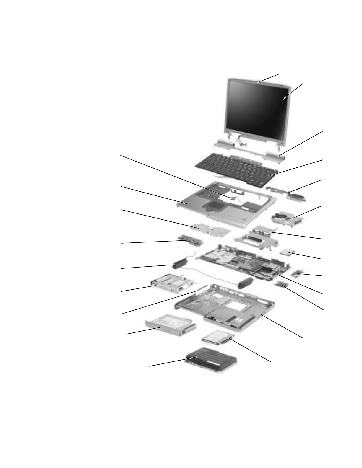
System Components 19

1 display latch 12 bottom case
2 display 13 hard drive
3 hinge cover 14 battery
4 keyboard 15 optical drive
5 palm rest shield 16 rubber bumper
www.dell.com | support.dell.com
6 microprocessor thermal-cooling
17 floppy drive
assembly
7 system board shield 18 speakers (2)
8 microprocessor module 19 charger board
9 power shield 20 video shield
10 system board 21 palm rest
11 modem 22 reserve battery
20 System Components

SECTION 4
Memory Module,
Modem, and Optical
Drive
4

Memory Module
Removing the Memory Module
NOTICE: Disconnect the computer and any attached devices from electrical
outlets, and remove any installed battery.
NOTICE: To avoid ESD, ground yourself by using a wrist grounding strap or
by touching an unpainted metal surface on the computer.
NOTICE: Read "Preparing to Work Inside the Computer" before performing
the following procedure.
www.dell.com | support.dell.com
1
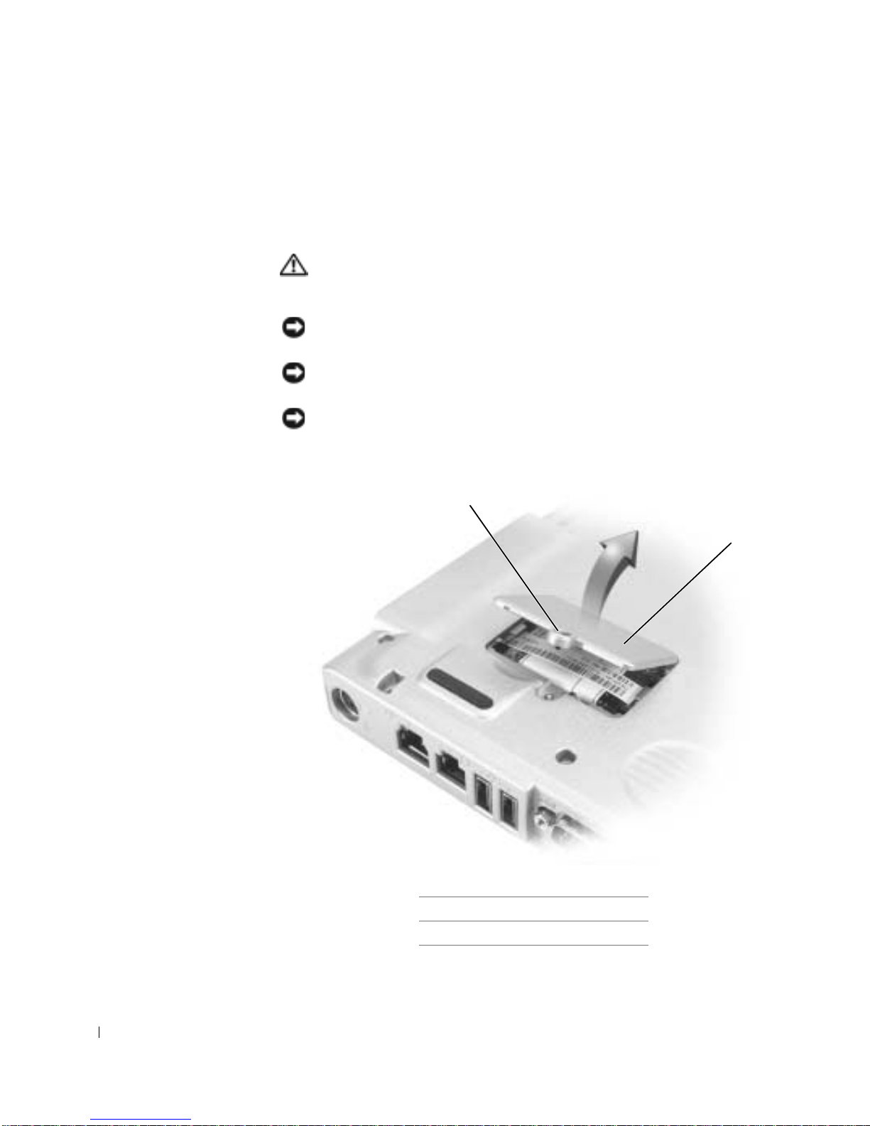
1 captive screw
2
1
22 Memory Module, Modem, and Optical Drive
2 memory module cover
Turn the computer over, and remove the memory module cover:
a Loosen the captive screw on the memory module cover.
b Lift the door.
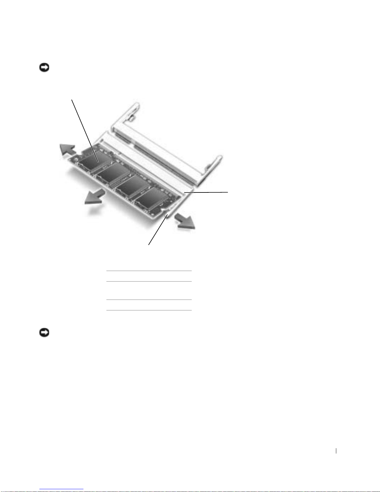
NOTICE: To prevent damage to the memory module connector, do not use
tools to spread securing clips that hold the memory module; use your fingers.
1
2
3
1 memory module
2 memory module
connector
3 securing clip
2
If you are installing a memory module, remove the existing module.
NOTICE: Handle memory modules by their edges, and do not touch the
components on a module.
a Use your fingertips to carefully spread apart the securing clips on
each end of the memory module connector. The module normally
pops up.
b Remove the module from the connector.
Memory Module, Modem, and Optical Drive 23
www.dell.com | support.dell.com
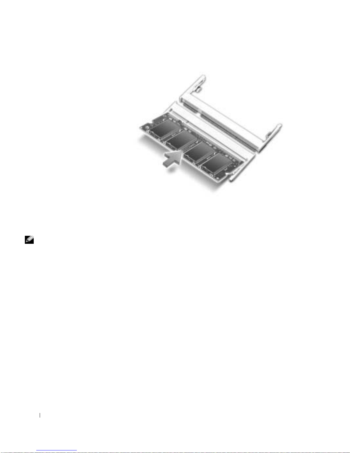
3 Ground yourself and install the new memory module:
HINT: If you are
installing one memory
module, install it in the
socket labeled "DIMM A."
If you are installing a
second module, install it
in the socket labeled
"DIMM B."
a Align the notch in the module with the slot in the center of the
connector at approximately a 45-degree angle.
b Slide the edge of the module firmly into the connector , and rotate
the module down until it clicks into place. If you do not feel a
click, remove the module and reinstall it.
24 Memory Module, Modem, and Optical Drive
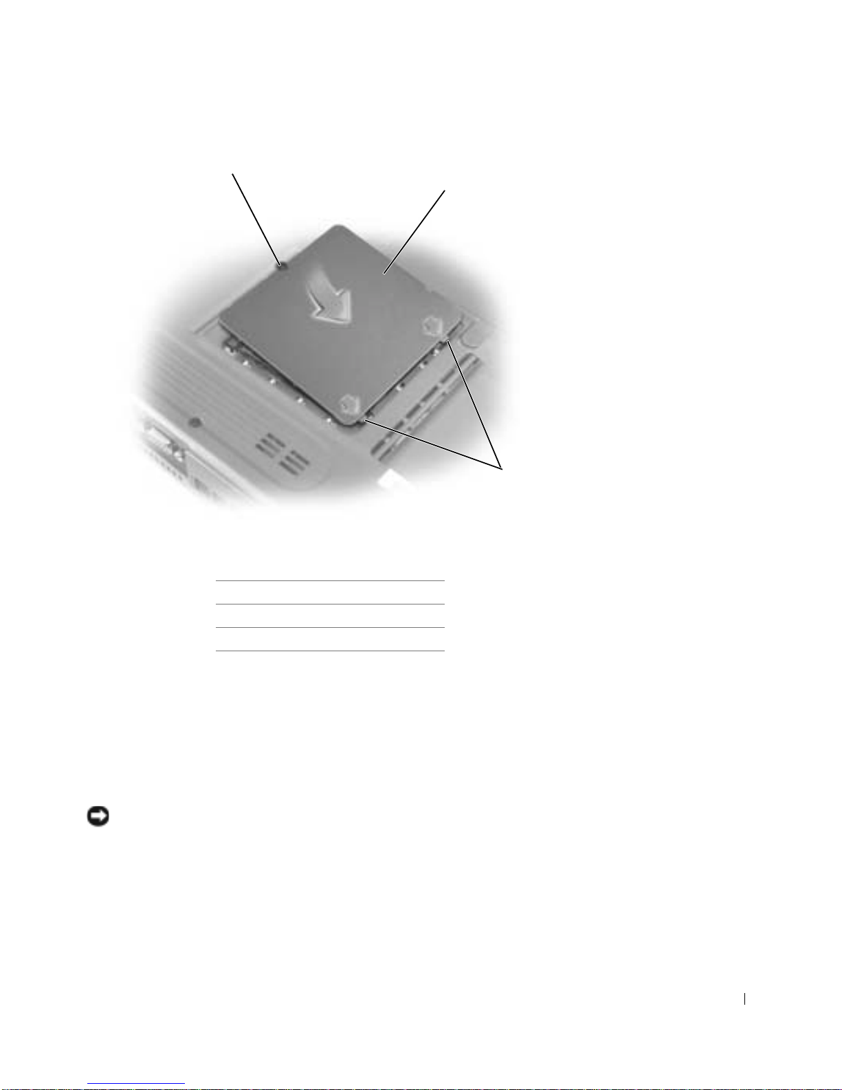
1
2
3
1 captive screw
2 memory module cover
3 tabs
4 Replace the cover:
a Place the memory module cover over the memory module
compartment so that the tabs on the back of the memory module
cover fit into the slots in th e bottom case.
b Rotate the memory module cover down and tighten the captive
screw.
NOTICE: If the memory module cover is difficult to close, remove the module
and reinstall it. Forcing the cover to close may damage your computer.
Insert the battery into the battery bay, or connect the AC adapter to
5
your computer and an electrical outlet.
6 Turn on the computer.
Memory Module, Modem, and Optical Drive 25
www.dell.com | support.dell.com
As the computer boots, it detects the additional memory and automatically
updates the system configuration information.
Modem
CAUTION: Before performing these procedures, shut down the
computer, disconnect it from the electrical outlet, and disco nne ct
the modem from the telephone wall jack.
NOTICE: Disconnect any attached devices from electrical outlets, and remove
any installed battery.
NOTICE: To avoid ESD, ground yourself by using a wrist grounding strap or
by touching an unpainted metal surface on the computer.
NOTICE: Read "Preparing to Work Inside the Computer" before performing
the following procedure.
1
2
26 Memory Module, Modem, and Optical Drive
1 captiv e sc rew
2 modem cover
 Loading...