

Dell SCv3000, SCv3020 Deployment Manual

SCv3000 and SCv3020 Storage System
Deployment Guide

Notes, Cautions, and Warnings
NOTE: A NOTE indicates important information that helps you make better use of your product.
CAUTION: A CAUTION indicates either potential damage to hardware or loss of data and tells you how to avoid the problem.
WARNING: A WARNING indicates a potential for property damage, personal injury, or death.
Copyright © 2018 Dell Inc. or its subsidiaries. All rights reserved. Dell, EMC, and other trademarks are trademarks of Dell Inc. or its subsidiaries. Other
trademarks may be trademarks of their respective owners.
2018-04
Rev. D

Contents
About This Guide.............................................................................................................................................. 7
Revision History..................................................................................................................................................................7
Audience..............................................................................................................................................................................7
Contacting Dell................................................................................................................................................................... 7
Related Publications...........................................................................................................................................................7
1 About the SCv3000 and SCv3020 Storage System........................................................................................9
Storage Center Hardware Components..........................................................................................................................9
SCv3000 and SCv3020 Storage System..................................................................................................................9
Expansion Enclosures.................................................................................................................................................10
Switches...................................................................................................................................................................... 10
Storage Center Communication..................................................................................................................................... 10
Front-End Connectivity............................................................................................................................................. 10
Back-End Connectivity.............................................................................................................................................. 16
System Administration............................................................................................................................................... 16
Storage Center Replication....................................................................................................................................... 16
SCv3000 and SCv3020 Storage System Hardware.................................................................................................... 17
SCv3000 and SCv3020 Storage System Front-Panel View................................................................................. 17
SCv3000 and SCv3020 Storage System Back-Panel View..................................................................................19
Expansion Enclosure Overview................................................................................................................................22
2 Install the Storage Center Hardware.............................................................................................................31
Unpacking Storage Center Equipment.......................................................................................................................... 31
Safety Precautions........................................................................................................................................................... 31
Installation Safety Precautions..................................................................................................................................31
Electrical Safety Precautions....................................................................................................................................32
Electrostatic Discharge Precautions........................................................................................................................32
General Safety Precautions...................................................................................................................................... 33
Prepare the Installation Environment.............................................................................................................................33
Install the Storage System in a Rack............................................................................................................................. 33
3 Connect the Front-End Cabling................................................................................................................... 36
Types of Redundancy for Front-End Connections...................................................................................................... 36
Port Redundancy....................................................................................................................................................... 36
Storage Controller Redundancy............................................................................................................................... 36
Connecting to Host Servers with Fibre Channel HBAs...............................................................................................37
Fibre Channel Zoning.................................................................................................................................................37
Cable the Storage System with 2-Port Fibre Channel IO Cards..........................................................................38
Cable the Storage System with 4-Port Fibre Channel IO Cards..........................................................................39
Labeling the Front-End Cables.................................................................................................................................40
Connecting to Host Servers with iSCSI HBAs or Network Adapters........................................................................ 41
Cable the Storage System with 2–Port iSCSI IO Cards........................................................................................ 41
Cable the Storage System with 4–Port iSCSI IO Cards....................................................................................... 42
Contents
3

Connect a Storage System to a Host Server Using an iSCSI Mezzanine Card................................................. 43
Labeling the Front-End Cables.................................................................................................................................44
Connecting to Host Servers with SAS HBAs...............................................................................................................45
Cable the Storage System with 4-Port SAS HBAs to Host Servers with One SAS HBA per Server.............45
Labeling the Front-End Cables.................................................................................................................................46
Attach Host Servers (Fibre Channel)............................................................................................................................ 47
Attach the Host Servers (iSCSI)................................................................................................................................... 48
Attach the Host Servers (SAS)......................................................................................................................................48
Connect the Management Ports to the Management Network............................................................................... 49
Labeling the Ethernet Management Cables...........................................................................................................49
4 Connect the Back-End Cabling.....................................................................................................................51
Expansion Enclosure Cabling Guidelines........................................................................................................................51
Back-End SAS Redundancy......................................................................................................................................51
Back-End Connections for an SCv3000 and SCv3020 Storage System With Expansion Enclosures..................51
SCv3000 and SCv3020 and One SCv300 and SCv320 Expansion Enclosure..................................................52
SCv3000 and SCv3020 and Two SCv300 and SCv320 Expansion Enclosures................................................ 53
SCv3000 and SCv3020 Storage System and One SCv360 Expansion Enclosure............................................54
SCv3000 and SCv3020 Storage System and Two SCv360 Expansion Enclosures..........................................54
Label the Back-End Cables............................................................................................................................................ 55
5 Discover and Congure the Storage Center.................................................................................................57
Connect Power Cables and Turn On the Storage System..........................................................................................57
Locate Your Service Tag..................................................................................................................................................59
Record System Information............................................................................................................................................59
Supported Operating Systems for Storage Center Automated Setup .................................................................... 59
Install and Use the Storage Manager Client................................................................................................................. 59
Discover and Select an Uninitialized Storage Center.................................................................................................. 59
Deploy the Storage Center Using the Direct Connect Method.................................................................................60
Customer Installation Authorization.............................................................................................................................. 60
Set System Information................................................................................................................................................... 61
Set Administrator Information.........................................................................................................................................61
Conrm the Storage Center Conguration...................................................................................................................61
Initialize the Storage Center............................................................................................................................................ 61
Congure Key Management Server Settings...............................................................................................................62
Create a Storage Type..................................................................................................................................................... 62
Congure Ports................................................................................................................................................................ 62
Congure Fibre Channel Ports................................................................................................................................. 62
Congure iSCSI Ports................................................................................................................................................63
Congure SAS Ports..................................................................................................................................................63
Congure Time Settings................................................................................................................................................. 64
Congure SMTP Server Settings.................................................................................................................................. 64
Using SupportAssist........................................................................................................................................................ 64
Enable SupportAssist ............................................................................................................................................... 64
Update the Storage Center............................................................................................................................................ 65
Complete the Conguration and Continue With Setup.............................................................................................. 65
Contents
4

Modify iDRAC Interface Settings for a Storage System.......................................................................................66
Uncongure Unused I/O Ports................................................................................................................................ 66
6 Perform Post-Setup Tasks........................................................................................................................... 67
Update Storage Center Using Storage Manager.........................................................................................................67
Check the Status of the Update.................................................................................................................................... 67
Change the Operation Mode of a Storage Center...................................................................................................... 68
Verify Connectivity and Failover.................................................................................................................................... 68
Create Test Volumes..................................................................................................................................................68
Test Basic Connectivity.............................................................................................................................................68
Test Storage Controller Failover...............................................................................................................................69
Test MPIO................................................................................................................................................................... 69
Clean Up Test Volumes............................................................................................................................................. 69
Send Diagnostic Data Using SupportAssist..................................................................................................................70
7 Adding or Removing Expansion Enclosures...................................................................................................71
Adding Expansion Enclosures to a Storage System Deployed Without Expansion Enclosures.............................. 71
Install New SCv300 and SCv320 Expansion Enclosures in a Rack...................................................................... 71
Add the SCv300 and SCv320 Expansion Enclosures to the A-Side of the Chain.............................................72
Add the SCv300 and SCv320 Expansion Enclosures to the B-Side of the Chain.............................................73
Install New SCv360 Expansion Enclosures in a Rack............................................................................................ 74
Add the SCv360 Expansion Enclosures to the A-Side of the Chain................................................................... 76
Add an SCv360 Expansion Enclosure to the B-Side of the Chain.......................................................................76
Adding a Single Expansion Enclosure to a Chain Currently in Service...................................................................... 78
Check the Drive Count..............................................................................................................................................79
Add an SCv300 and SCv320 Expansion Enclosure to the A-Side of the Chain................................................ 79
Add an SCv300 and SCv320 Expansion Enclosure to the B-Side of the Chain................................................80
Add an SCv360 Expansion Enclosure to the A-Side of the Chain.......................................................................82
Add an SCv360 Expansion Enclosure to the B-Side of the Chain.......................................................................83
Removing an Expansion Enclosure from a Chain Currently in Service..................................................................... 85
Release the Drives in the Expansion Enclosure......................................................................................................86
Disconnect the SCv300 and SCv320 Expansion Enclosure from the A-Side of the Chain.............................86
Disconnect the SCv300 and SCv320 Expansion Enclosure from the B-Side of the Chain.............................88
Disconnect the SCv360 Expansion Enclosure from the A-Side of the Chain....................................................89
Disconnect the SCv360 Expansion Enclosure from the B-Side of the Chain.................................................... 91
8 Troubleshooting Storage Center Deployment...............................................................................................94
Troubleshooting Storage Controllers............................................................................................................................. 94
Troubleshooting Hard Drives.......................................................................................................................................... 94
Troubleshooting Expansion Enclosures......................................................................................................................... 94
A Set Up a Local Host or VMware Host.......................................................................................................... 95
Set Up a Local Host from Initial Setup.......................................................................................................................... 95
Set Up a VMware ESXi Host from Initial Setup...........................................................................................................95
Set Up Multiple VMware ESXi Hosts in a VMware vSphere Cluster........................................................................96
B Initialize the Storage Center Using the USB Serial Port...............................................................................97
Install the USB Serial Port Driver .................................................................................................................................. 97
Contents
5

Establish a Terminal Session........................................................................................................................................... 97
Discover the Storage Center Using the Setup Utility................................................................................................. 98
C Worksheet to Record System Information...................................................................................................99
Storage Center Information............................................................................................................................................99
iSCSI Fault Domain Information..................................................................................................................................... 99
Additional Storage Center Information........................................................................................................................ 100
Fibre Channel Zoning Information................................................................................................................................ 100
D HBA Server Settings..................................................................................................................................102
Settings by HBA Manufacturer.....................................................................................................................................102
Dell 12 Gb SAS HBAs............................................................................................................................................... 102
Cisco Fibre Channel HBAs.......................................................................................................................................102
Emulex HBAs.............................................................................................................................................................102
QLogic HBAs.............................................................................................................................................................103
Settings by Server Operating System......................................................................................................................... 104
Citrix XenServer....................................................................................................................................................... 104
Microsoft Windows Server..................................................................................................................................... 105
Novell Netware ........................................................................................................................................................ 106
Red Hat Enterprise Linux.........................................................................................................................................106
E iSCSI Settings............................................................................................................................................108
Flow Control Settings.................................................................................................................................................... 108
Ethernet Flow Control............................................................................................................................................. 108
Switch Ports and Flow Control...............................................................................................................................108
Flow Control..............................................................................................................................................................108
Jumbo Frames and Flow Control........................................................................................................................... 108
Other iSCSI Settings......................................................................................................................................................109
6
Contents

About This Guide
This guide describes the features and technical specications of the SCv3000 and SCv3020 storage system.
Revision History
Document Number: 680-136-001
Revision Date Description
A October 2017 Initial release
B November 2017 Corrections to SCv360 cabling
C February 2017 Added support information for back-end cabling
D April 2017 Remove restrictions on mezzanine card use
Audience
The information provided in this guide is intended for storage or network administrators and deployment personnel.
Preface
Contacting Dell
Dell provides several online and telephone-based support and service options. Availability varies by country and product, and some services
might not be available in your area.
To contact Dell for sales, technical support, or customer service issues, go to www.dell.com/support.
• For customized support, type your system service tag on the support page and click Submit.
• For general support, browse the product list on the support page and select your product.
Related Publications
The following documentation provides additional information about the SCv3000 and SCv3020 storage system.
• SCv3000 and SCv3020 Storage System Getting Started Guide
Provides information about an SCv3000 and SCv3020 storage system, such as installation instructions and technical specications.
• SCv3000 and SCv3020 Storage System Owner’s Manual
Provides information about an SCv3000 and SCv3020 storage system, such as hardware features, replacing customer-replaceable
components, and technical specications.
• SCv3000 and SCv3020 Storage System Service Guide
Provides information about SCv3000 and SCv3020 storage system hardware, system component replacement, and system
troubleshooting.
• Storage Center Release Notes
Provides information about new features and known and resolved issues for the Storage Center software.
• Storage Center Update Utility Administrator’s Guide
Describes how to use the Storage Center Update Utility to install Storage Center software updates. Updating Storage Center software
using the Storage Center Update Utility is intended for use only by sites that cannot update Storage Center using standard methods.
• Storage Center Software Update Guide
About This Guide 7

Describes how to update Storage Center software from an earlier version to the current version.
• Storage Center Command Utility Reference Guide
Provides instructions for using the Storage Center Command Utility. The Command Utility provides a command-line interface (CLI) to
enable management of Storage Center functionality on Windows, Linux, Solaris, and AIX platforms.
• Storage Center Command Set for Windows PowerShell
Provides instructions for getting started with Windows PowerShell cmdlets and scripting objects that interact with the Storage Center
using the PowerShell interactive shell, scripts, and PowerShell hosting applications. Help for individual cmdlets is available online.
• Storage Manager Installation Guide
Contains installation and setup information.
• Storage Manager Administrator’s Guide
Contains in-depth feature conguration and usage information.
• Storage Manager Release Notes
Provides information about Storage Manager releases, including new features and enhancements, open issues, and resolved issues.
• Dell TechCenter
Provides technical white papers, best practice guides, and frequently asked questions about Dell Storage products. Go to http://
en.community.dell.com/techcenter/storage/.
8 About This Guide

1
About the SCv3000 and SCv3020 Storage
System
The SCv3000 and SCv3020 storage system provides the central processing capabilities for the Storage Center Operating System (OS),
application software, and management of RAID storage.
The SCv3000 and SCv3020 storage system holds the physical drives that provide storage for the Storage Center. If additional storage is
needed, the SCv3000 and SCv3020 supports SCv300 and SCv320 and SCv360 expansion enclosures.
Topics:
• Storage Center Hardware Components
• Storage Center Communication
• SCv3000 and SCv3020 Storage System Hardware
Storage Center Hardware Components
The Storage Center described in this document consists of an SCv3000 and SCv3020 storage system, expansion enclosures, and
enterprise-class switches.
To allow for storage expansion, the SCv3000 and SCv3020 storage system supports multiple SCv300 and SCv320 and SCv360 expansion
enclosures.
: The cabling between the storage system, switches, and host servers is referred to as front‐end connectivity. The cabling
NOTE
between the storage system and expansion enclosures is referred to as back-end connectivity.
SCv3000 and SCv3020 Storage System
The SCv3000 and SCv3020 storage systems contain two redundant power supply/cooling fan modules, and two storage controllers with
multiple I/O ports. The I/O ports provide communication with host servers and expansion enclosures. The SCv3000 storage system
contains up to 16 3.5-inch drives and the SCv3020 storage system contains up to 30 2.5-inch drives.
The SCv3000 Series Storage Center supports up to 222 drives per Storage Center system. This total includes the drives in the storage
system chassis and the drives in the expansion enclosures. The SCv3000 and SCv3020 require a minimum of seven hard disk drives
(HDDs) or four solid-state drives (SSDs) installed in the storage system chassis or an expansion enclosure.
Conguration
SCv3000 storage system with SCv300 or SCv320 expansion enclosure 208
SCv3000 storage system with SCv360 expansion enclosure 196
SCv3020 storage system with SCv300 or SCv320 expansion enclosure 222
SCv3020 storage system with SCv360 expansion enclosure 210
Number of Drives Supported
About the SCv3000 and SCv3020 Storage System 9

Expansion Enclosures
Expansion enclosures allow the data storage capabilities of the SCv3000 and SCv3020 storage system to be expanded beyond the 16 or
30 drives in the storage system chassis.
The SCv3000 and SCv3020 support up to 16 SCv300 expansion enclosures, up to eight SCv320 expansion enclosures, and up to three
SCv360 expansion enclosures.
Switches
Dell oers enterprise-class switches as part of the total Storage Center solution.
The SCv3000 and SCv3020 storage system supports Fibre Channel (FC) and Ethernet switches, which provide robust connectivity to
servers and allow for the use of redundant transport paths. Fibre Channel (FC) or Ethernet switches can provide connectivity to a remote
Storage Center to allow for replication of data. In addition, Ethernet switches provide connectivity to a management network to allow
conguration, administration, and management of the Storage Center.
Storage Center Communication
A Storage Center uses multiple types of communication for both data transfer and administrative functions.
Storage Center communication is classied into three types: front end, back end, and system administration.
Front-End Connectivity
Front-end connectivity provides I/O paths from servers to a storage system and replication paths from one Storage Center to another
Storage Center. The SCv3000 and SCv3020 storage system provides the following types of front-end connectivity:
• Fibre Channel – Hosts, servers, or network-attached storage (NAS) appliances access storage by connecting to the storage system
Fibre Channel ports through one or more Fibre Channel switches. Connecting host servers directly to the storage system, without using
Fibre Channel switches, is not supported.
• iSCSI – Hosts, servers, or network-attached storage (NAS) appliances access storage by connecting to the storage system iSCSI ports
through one or more Ethernet switches. Connecting host servers directly to the storage system, without using Ethernet switches, is
not supported.
• SAS – Hosts or servers access storage by connecting directly to the storage system SAS ports.
When replication is licensed, the SCv3000 and SCv3020 can use the front-end Fibre Channel or iSCSI ports to replicate data to another
Storage Center.
10
About the SCv3000 and SCv3020 Storage System

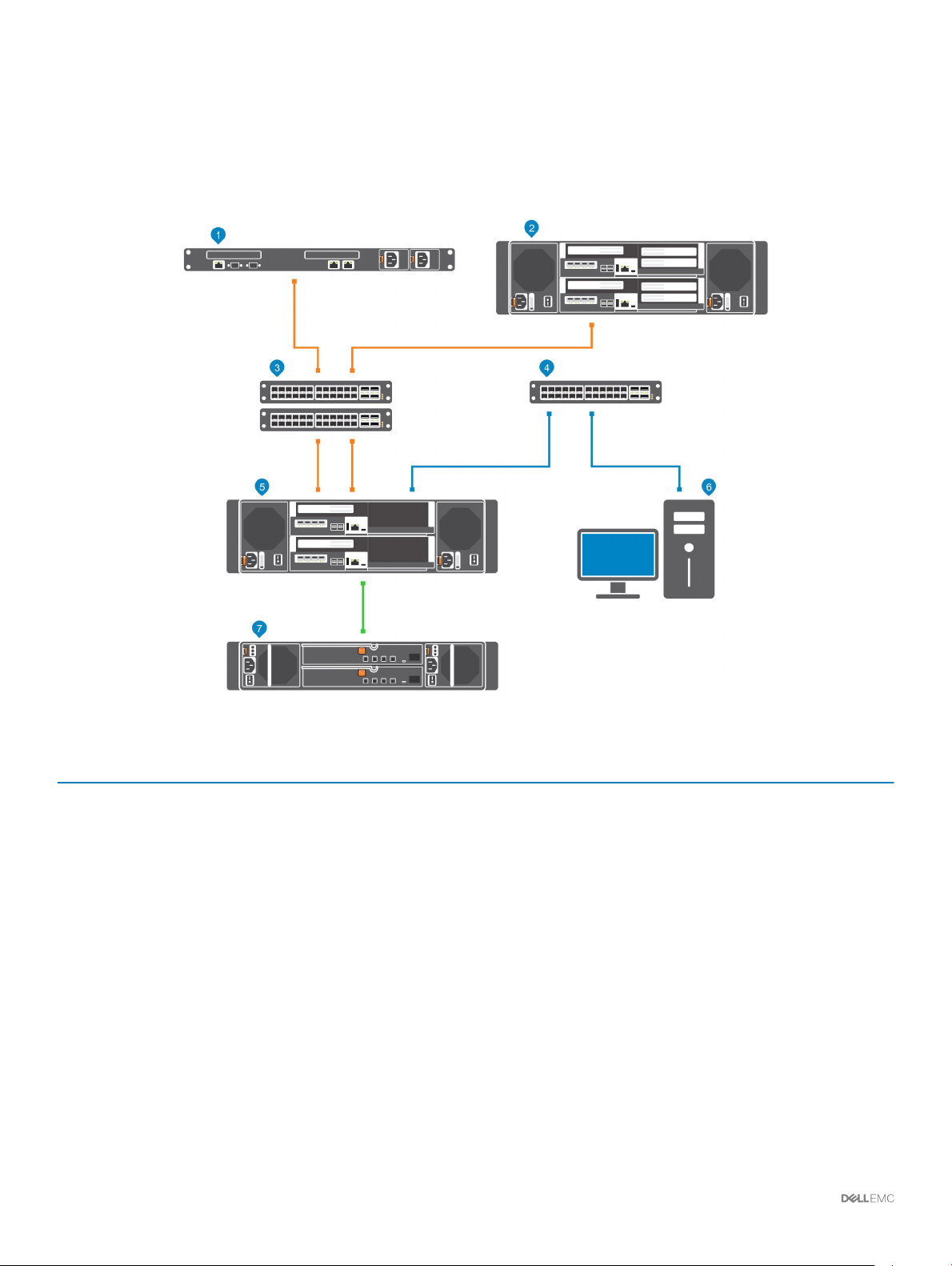
SCv3000 and SCv3020 Storage System With Fibre Channel Front-End
Connectivity
A storage system with Fibre Channel front-end connectivity can communicate with the following components of a Storage Center system.
Figure 1. Storage System With Fibre Channel Front-End Connectivity
Item
1 Server with Fibre Channel host bus adapters (HBAs) 8 Gbps or 16 Gbps Front End
2 Remote Storage Center connected via Fibre Channel for
3 Fibre Channel switch (A pair of Fibre Channel switches are
4 Ethernet switch for the management network 1 Gbps System Administration
5 SCv3000 and SCv3020 with FC front-end connectivity 8 Gbps or 16 Gbps Front End
6 Storage Manager (Installed on a computer connected to the
7 SCv300 and SCv320 expansion enclosures
Description Speed Communication Type
8 Gbps or 16 Gbps Front End
replication
8 Gbps or 16 Gbps Front End
recommended for optimal redundancy and connectivity)
Up to 1 Gbps System Administration
storage system through the Ethernet switch)
12 Gbps per channel
Back End
About the SCv3000 and SCv3020 Storage System 11
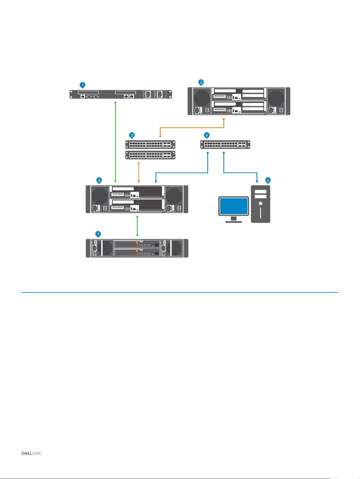
SCv3000 and SCv3020 Storage System With iSCSI Front-End
Connectivity
A storage system with iSCSI front-end connectivity can communicate with the following components of a Storage Center system.
Figure 2. Storage System With iSCSI Front-End Connectivity
Item
1 Server with Ethernet (iSCSI) ports or iSCSI host bus adapters
2 Remote Storage Center connected via iSCSI for replication 1 GbE or 10 GbE Front End
3 Ethernet switch (A pair of Ethernet switches is recommended
4 Ethernet switch for the management network 1 Gbps System Administration
5 SCv3000 and SCv3020 with iSCSI front-end connectivity 1 GbE or 10 GbE Front End
6 Storage Manager (Installed on a computer connected to the
7 SCv300 and SCv320 expansion enclosures
Description Speed Communication Type
1 GbE or 10 GbE Front End
(HBAs)
1 GbE or 10 GbE Front End
for optimal redundancy and connectivity)
Up to 1 Gbps System Administration
storage system through the Ethernet switch)
12 Gbps per channel
Back End
12 About the SCv3000 and SCv3020 Storage System
SCv3000 and SCv3020 Storage System With Front-End SAS Connectivity
The SCv3000 and SCv3020 storage system with front-end SAS connectivity can communicate with the following components of a
Storage Center system.
Figure 3. Storage System With Front-End SAS Connectivity
Item
1 Server with SAS host bus adapters (HBAs) 12 Gbps per channel Front End
2 Remote Storage Center connected via iSCSI for replication 1 GbE or 10 GbE Front End
3 Ethernet switch (A pair of Ethernet switches is
4 Ethernet switch for the management network Up to 1 GbE System Administration
5 SCv3000 and SCv3020 with front-end SAS connectivity 12 Gbps per channel Front End
6 Storage Manager (Installed on a computer connected to
7 SCv300 and SCv320 expansion enclosures 12 Gbps per channel Back End
Description Speed Communication Type
1 GbE or 10 GbE Front End
recommended for optimal redundancy and connectivity)
Up to 1 Gbps System Administration
the storage system through the Ethernet switch)
About the SCv3000 and SCv3020 Storage System 13
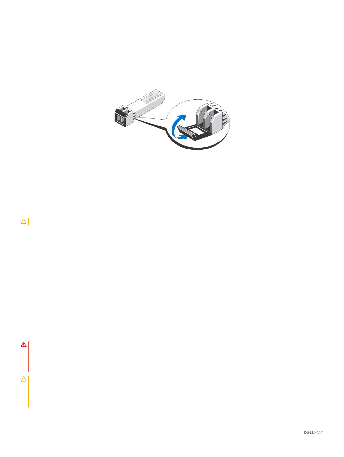
Using SFP+ Transceiver Modules
You can connect to the front-end port of a storage controller using a direct-attached SFP+ cable or an SFP+ transceiver module. An
SCv3000 and SCv3020 storage system with 16 Gb Fibre Channel or 10 GbE iSCSI storage controllers uses short-range small-form-factor
pluggable (SFP+) transceiver modules.
Figure 4. SFP+ Transceiver Module With a Bail Clasp Latch
The SFP+ transceiver modules are installed into the front-end ports of a storage controller.
Guidelines for Using SFP+ Transceiver Modules
Before installing SFP+ transceiver modules and ber-optic cables, read the following guidelines.
CAUTION
• Use only Dell-supported SFP+ transceiver modules with the Storage Center. Other generic SFP+ transceiver modules are not
supported and might not work with the Storage Center.
• The SFP+ transceiver module housing has an integral guide key that is designed to prevent you from inserting the transceiver module
incorrectly.
• Use minimal pressure when inserting an SFP+ transceiver module into a Fibre Channel port. Forcing the SFP+ transceiver module into a
port could damage the transceiver module or the port.
• The SFP+ transceiver module must be installed into a port before you connect the ber-optic cable.
• The ber-optic cable must be removed from the SFP+ transceiver module before you remove the transceiver module from the port.
: When handling static-sensitive devices, take precautions to avoid damaging the product from static electricity.
Install an SFP+ Transceiver Module
Use the following procedure to install an SFP+ transceiver module into a storage controller.
About this task
Read the following cautions and information before installing an SFP+ transceiver module.
WARNING
• Do not open any panels, operate controls, make adjustments, or perform procedures to a laser device other than those specied in
• Do not stare into the laser beam.
CAUTION: Transceiver modules can be damaged by electrostatic discharge (ESD). To prevent ESD damage to the transceiver
module, take the following precautions:
: To reduce the risk of injury from laser radiation or damage to the equipment, take the following precautions:
this document.
• Wear an antistatic discharge strap while handling transceiver modules.
• Place transceiver modules in antistatic packing material when transporting or storing them.
14 About the SCv3000 and SCv3020 Storage System
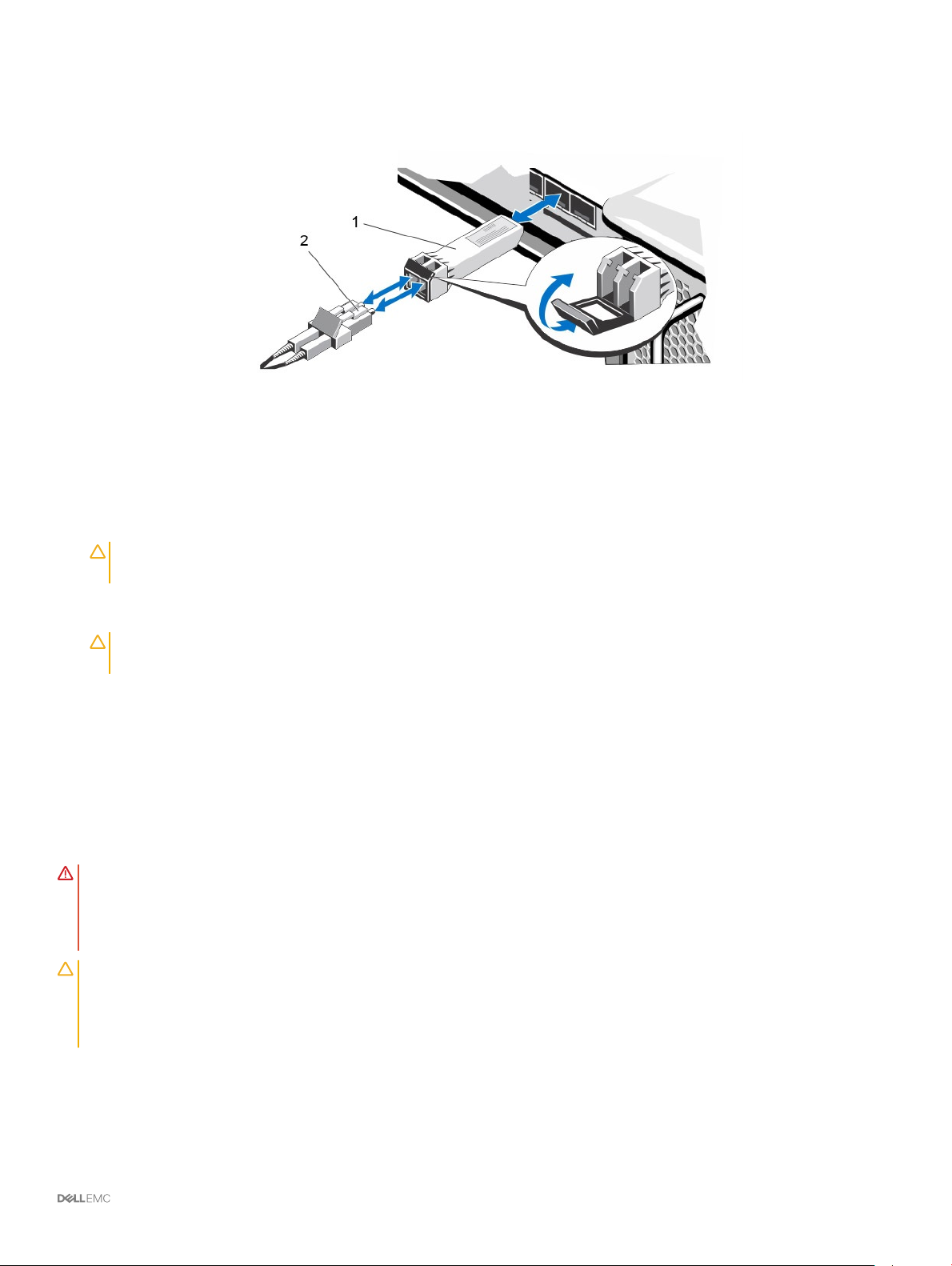
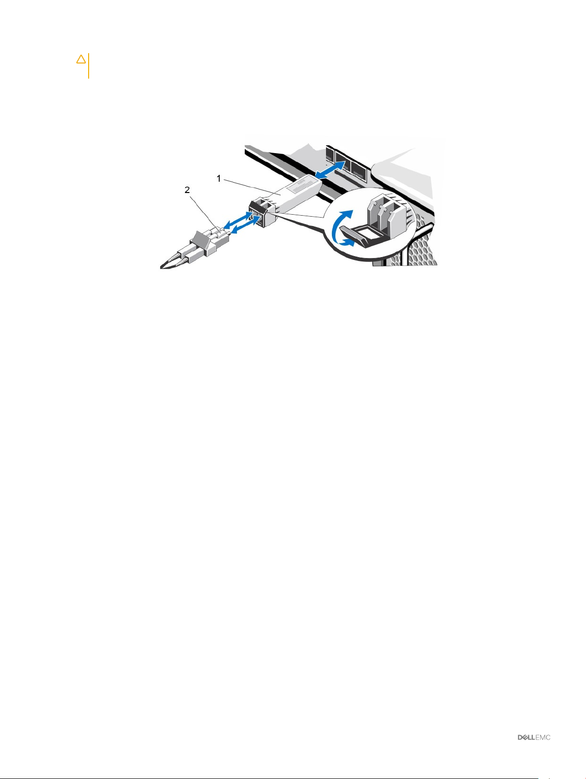
Steps
1 Position the transceiver module so that the key is oriented correctly to the port in the storage controller.
Figure 5. Install the SFP+ Transceiver Module
1 SFP+ transceiver module 2 Fiber-optic cable connector
2 Insert the transceiver module into the port until it is rmly seated and the latching mechanism clicks.
The transceiver modules are keyed so that they can be inserted only with the correct orientation. If a transceiver module does not
slide in easily, ensure that it is correctly oriented.
CAUTION
module.
3 Position the ber-optic cable so that the key (the ridge on one side of the cable connector) is aligned with the slot in the transceiver
module.
CAUTION
replace the protective covers on the ends of the cable.
4 Insert the ber-optic cable into the transceiver module until the latching mechanism clicks.
: To reduce the risk of damage to the equipment, do not use excessive force when inserting the transceiver
: Touching the end of a ber-optic cable damages the cable. Whenever a ber-optic cable is not connected,
Remove an SFP+ Transceiver Module
Complete the following steps to remove an SFP+ transceiver module from a storage controller.
Prerequisite
Use failover testing to make sure that the connection between host servers and the Storage Center remains up if the port is disconnected.
About this task
Read the following cautions and information before beginning the removal and replacement procedures.
WARNING
• Do not open any panels, operate controls, make adjustments, or perform procedures to a laser device other than those specied in
• Do not stare into the laser beam.
CAUTION: Transceiver modules can be damaged by electrostatic discharge (ESD). To prevent ESD damage to the transceiver
module, take the following precautions:
• Wear an antistatic discharge strap while handling modules.
• Place modules in antistatic packing material when transporting or storing them.
Steps
1 Remove the ber-optic cable that is inserted into the transceiver.
a Make sure the ber-optic cable is labeled before removing it.
b Press the release clip on the bottom of the cable connector to remove the ber-optic cable from the transceiver.
: To reduce the risk of injury from laser radiation or damage to the equipment, take the following precautions:
this document.
About the SCv3000 and SCv3020 Storage System
15
CAUTION: Touching the end of a ber-optic cable damages the cable. Whenever a ber-optic cable is not connected,
replace the protective covers on the ends of the cables.
2 Open the transceiver module latching mechanism.
3 Grasp the bail clasp latch on the transceiver module and pull the latch out and down to eject the transceiver module from the socket.
4 Slide the transceiver module out of the port.
Figure 6. Remove the SFP+ Transceiver Module
1 SFP+ transceiver module 2 Fiber-optic cable connector
Back-End Connectivity
Back-end connectivity is strictly between the storage system and expansion enclosures.
The SCv3000 and SCv3020 storage system supports back-end connectivity to multiple SCv300, SCv320, and SCv360 expansion
enclosures.
System Administration
To perform system administration, the Storage Center communicates with computers using the Ethernet management (MGMT) port on
the storage controllers.
The Ethernet management port is used for Storage Center conguration, administration, and management.
Storage Center Replication
Storage Center sites can be collocated or remotely connected and data can be replicated between sites. Storage Center replication can
duplicate volume data to another site in support of a disaster recovery plan or to provide local access to a remote data volume. Typically,
data is replicated remotely as part of an overall disaster avoidance or recovery plan.
The SCv3000 and SCv3020 storage system supports replication to the storage systems listed below. However, a Storage Manager Data
Collector must be used to replicate data between the storage systems. For more information about installing and managing the Data
Collector and setting up replications, see the Storage Manager Installation Guide.
• SCv3000 series
• SC4020
• SC5020 series
• SC7020 series
• SC8000
About the SCv3000 and SCv3020 Storage System
16
• SC9000
SCv3000 and SCv3020 Storage System Hardware
The SCv3000 and SCv3020 storage system ships with Dell Enterprise Plus Value drives, two redundant power supply/cooling fan modules,
and two redundant storage controllers.
Each storage controller contains the front-end, back-end, and management communication ports of the storage system.
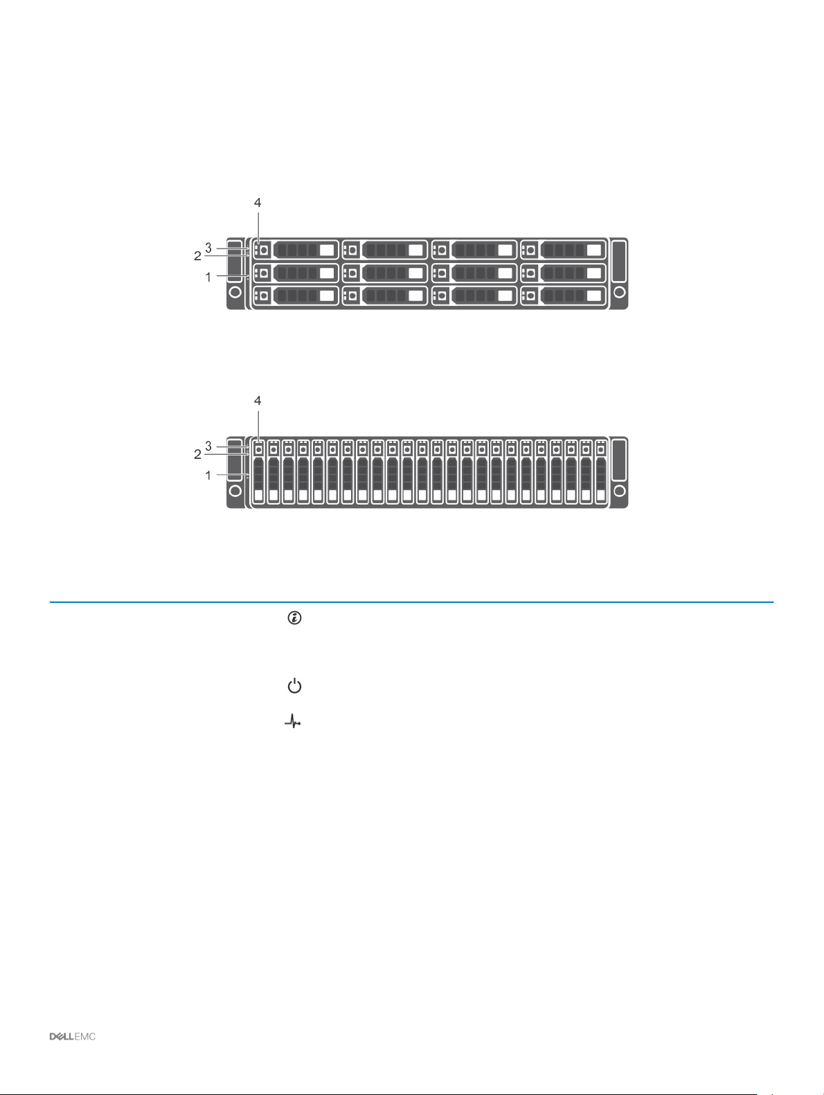
SCv3000 and SCv3020 Storage System Front-Panel View
The front panel of the storage system contains power and status indicators, and a system identication button.
In addition, the hard drives are installed and removed through the front of the storage system chassis.
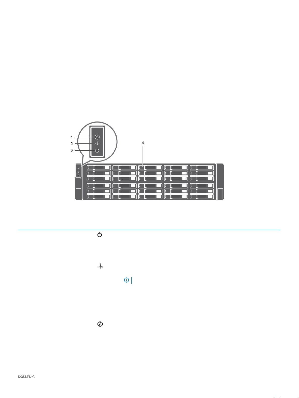
Figure 7. SCv3000 and SCv3020 Storage System Front-Panel View
Item
1 Power indicator Lights when the storage system power is on
2 Status indicator Lights when the startup process for both storage controllers is complete with no
3 Identication button Blinking blue continuously – A user sent a command to the storage system to
Name Icon Description
• O – No power
• On steady green – At least one power supply is providing power to the storage
system
faults detected.
NOTE: The startup process can take 5–10 minutes or more.
• O – One or both storage controllers are running startup routines, or a fault
has been detected during startup
• On steady blue – Both storage controllers have completed the startup process
and are in normal operation
• Blinking amber – Fault detected
make the LED blink so that the user can identify the storage system in the rack.
• The identication LED blinks on the control panel of the chassis, to allow users
to nd the storage system when looking at the front of the rack.
• The identication LEDs on the storage controllers also blink, which allows users
to nd the storage system when looking at the back of the rack.
About the SCv3000 and SCv3020 Storage System 17
Item Name Icon Description
4 Hard drives — Can have up to 30 internal 2.5-inch SAS hard drives
SCv3000 and SCv3020 Storage System Drives
The SCv3000 and SCv3020 storage system supports Dell Enterprise Plus Value drives.
The drives in an SCv3000 storage system are installed horizontally. The drives in an SCv3020 storage system are installed vertically. The
indicators on the drives provide status and activity information.
Figure 8. SCv300 and SCv320 Expansion Enclosure Drive Indicators
Item Control/Feature Indicator Code
1 Drive activity indicator
• Blinking green – Drive has I/O activity
• Steady green – Drive is detected and has no faults
2 Drive status indicator
• Steady green – Normal operation
• Blinking green – A command was sent to the drive to make the LED blink so that you can
identify the drive in the rack.
• Blinking amber – Hardware or rmware fault
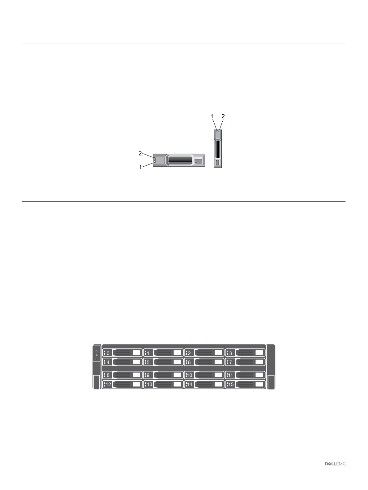
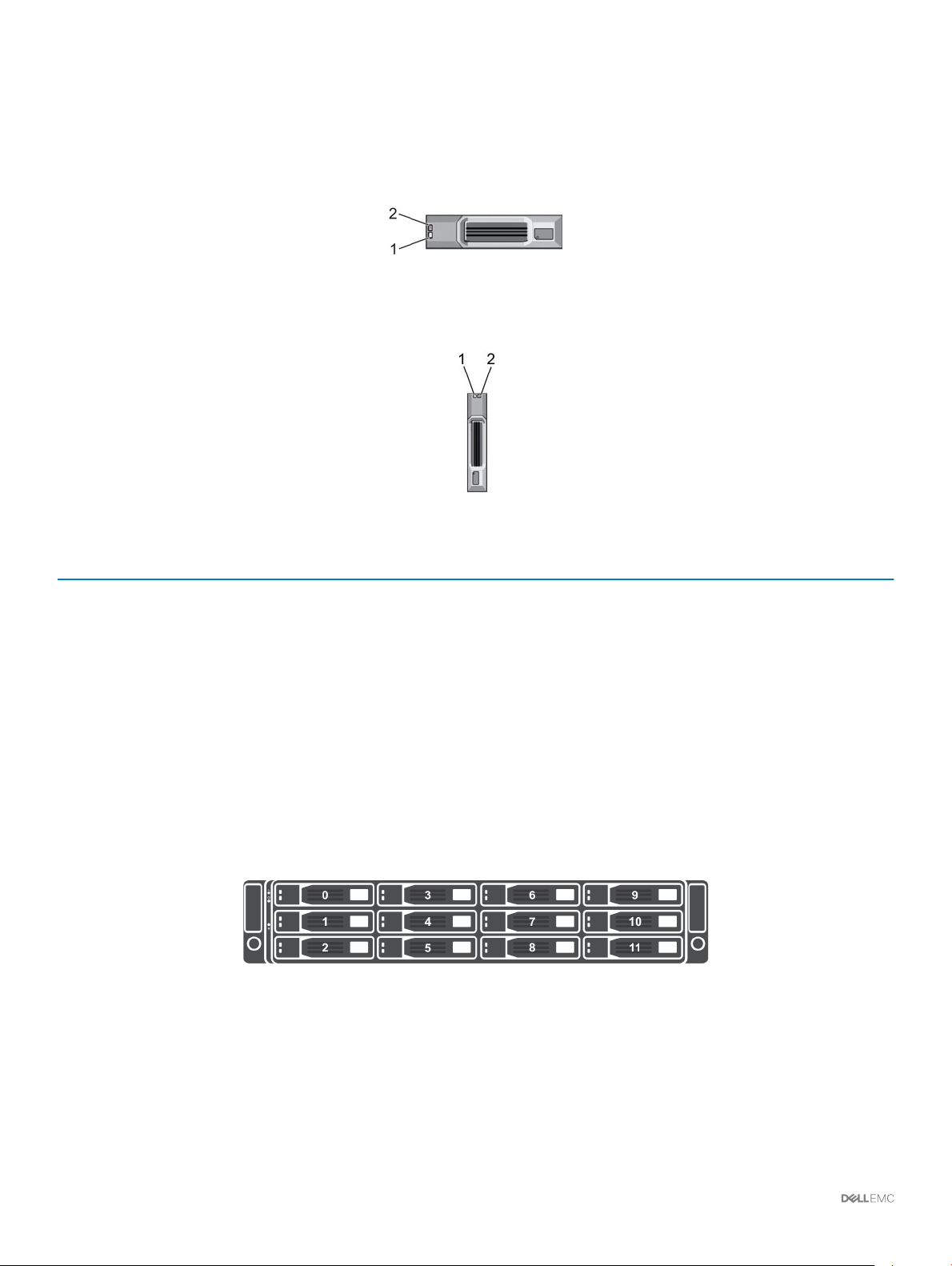
SCv3000 and SCv3020 Storage System Drive Numbering
The storage system holds up to 16 or 30 drives, which are numbered from left to right in rows starting from 0 at the top-left drive. Drive
numbers increment from left to right, and then top to bottom such that the rst row of drives is numbered from 0 to 4 from left to right,
and the second row of drives is numbered from 5 to 9 from left to right.
Storage Manager identies drives as XX-YY, where XX is the number of the unit ID of the storage system and YY is the drive position
inside the
Figure 9. SCv3000 Storage System Drive Numbering
storage system.
About the SCv3000 and SCv3020 Storage System
18

Figure 10. SCv3020 Storage System Drive Numbering
SCv3000 and SCv3020 Storage System Back-Panel View
The back panel of the storage system contains the storage controller indicators and power supply indicators.
Figure 11. SCv3000 and SCv3020 Storage System Back-Panel View
Item
1 Power supply/cooling fan
2 Storage controller (2) — Each storage controller contains:
3 Power switch (2) — Controls power for the storage system. Each power supply/cooling fan module has
Name Icon Description
Contains power supplies and fans that provide cooling for the storage system, with
module (2)
AC input to the power supply of 200–240 V. In Storage Manager, the power
supply/cooling fan module on the left side of the back panel is Power Supply 1 and
power supply/cooling fan module on the right side of the back panel is Power
Supply 2.
• Optional 10 GbE iSCSI mezzanine card with four SFP+ ports or four RJ45
10GBASE-T ports
• One expansion slot for a front-end I/O card:
– Fibre Channel
– iSCSI
– SAS
• SAS expansion ports – Two 12 Gbps SAS ports for back-end connectivity to
expansion enclosures
• USB port – Single USB 2.0 port
• MGMT port – Embedded Ethernet port for system management
• Serial port – Micro-USB serial port used for an alternative initial conguration
and support-only functions
one power switch.
About the SCv3000 and SCv3020 Storage System 19
Item Name Icon Description
4 Power supply/cooling fan
module LED handle
5 Power socket (2) — Accepts the following standard computer power cords:
—
The handle of the power supply/cooling fan module indicates the DC power status
of the power supply and the fans.
• Not lit – No power
• Solid green – Power supply has valid power source and is operational
• Blinking amber – Error condition in the power supply
• Blinking green – Firmware is being updated.
• Blinking green then o – Power supply mismatch
• IEC320-C13 for deployments worldwide
• IEC60320-C19 for deployments in Japan
Power Supply and Cooling Fan Modules
The SCv3000 and SCv3020 storage system supports two hot-swappable power supply/cooling fan modules.
The cooling fans and the power supplies are integrated into the power supply/cooling fan module and cannot be replaced separately. If one
power supply/cooling fan module fails, the second module continues to provide power to the storage system.
NOTE: When a power supply/cooling fan module fails, the cooling fan speed in the remaining module increases signicantly to
provide adequate cooling. The cooling fan speed decreases gradually when a new power supply/cooling fan module is installed.
CAUTION: A single power supply/cooling fan module can be removed from a powered on storage system for no more than 90
seconds. If a power supply/cooling fan module is removed for longer than 90 seconds, the storage system might shut down
automatically to prevent damage.
SCv3000 and SCv3020 Storage Controller Features and Indicators
The SCv3000 and SCv3020 storage system includes two storage controllers in two interface slots.
SCv3000 and SCv3020 Storage Controller
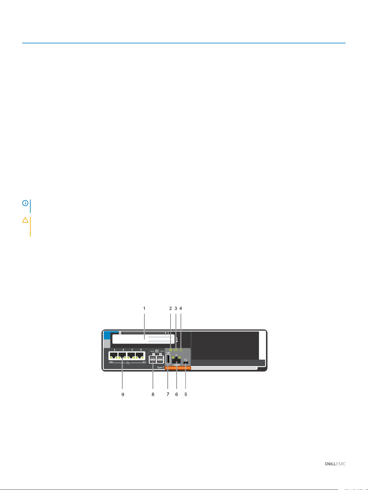
The following gure shows the features and indicators on the storage controller.
Figure 12. SCv3000 and SCv3020 Storage Controller
About the SCv3000 and SCv3020 Storage System
20

Item Control/Feature Icon Description
1 I/O card slot
Fibre Channel I/O card – Ports are numbered 1 to 4 from left to right
• The LEDs on the 16 Gb Fibre Channel ports have the following meanings:
– All o – No power
– All on – Booting up
– Blinking amber – 4 Gbps activity
– Blinking green – 8 Gbps activity
– Blinking yellow – 16 Gbps activity
– Blinking amber and yellow – Beacon
– All blinking (simultaneous) – Firmware initialized
– All blinking (alternating) – Firmware fault
• The LEDs on the 32 Gb Fibre Channel ports have the following meanings:
– All o – No power
– All on – Booting up
– Blinking amber – 8 Gbps activity
– Blinking green – 16 Gbps activity
– Blinking yellow – 32 Gbps activity
– Blinking amber and yellow – Beacon
– All blinking (simultaneous) – Firmware initialized
– All blinking (alternating) – Firmware fault
iSCSI I/O card – Ports are numbered 1 to 4 from left to right
2
3 Cache to Flash (C2F)
4 Health status
Identication LED Blinking blue continuously – A command was sent to the storage system to make
: The iSCSI I/O card supports Data Center Bridging (DCB), but
NOTE
the mezzanine card does not support DCB.
• The LEDs on the iSCSI ports have the following meanings:
– O – No power
– Steady Amber – Link
– Blinking Green – Activity
SAS I/O card – Ports are numbered 1 to 4 from left to right
The SAS ports on SAS I/O cards do not have LEDs.
the LED blink so that you can identify the storage system in the rack.
The identication LED blinks on the control panel of the chassis, which allows
users to nd the storage system when looking at the front of the rack.
The identication LEDs on the storage controllers also blink, which allows users to
nd the storage system when looking at the back of the rack.
• O – Running normally
• Blinking green – Running on battery (shutting down)
• O – Unpowered
• Blinking amber
– Slow blinking amber (2s on, 1s o) – Controller hardware fault was
detected. Use Storage Manager to view specic details about the
hardware fault.
– Fast blinking amber (4x per second) – Power good and the pre-operating
system is booting
• Blinking green
– Slow blinking green (2s on, 1s o) – Operating system is booting
About the SCv3000 and SCv3020 Storage System 21

Item Control/Feature Icon Description
– Blinking green (1s on, 1s o) – System is in safe mode
– Fast blinking green (4x per second) – Firmware is updating
• Solid green – Running normal operation
5 Serial port (micro USB) Used under the supervision of technical support to troubleshoot and support
systems.
6 MGMT port — Ethernet port used for storage system management and access to Storage
Manager.
Two LEDs with the port indicate link status (left LED) and activity status (right
LED):
• Link and activity indicators are o – Not connected to the network
• Link indicator is green – The NIC is connected to a valid network at its
maximum port speed.
• Link indicator is amber – The NIC is connected to a valid network at less than
its maximum port speed.
• Activity indicator is blinking green – Network data is being sent or received.
7 USB port One USB 2.0 connector that is used for SupportAssist diagnostic les when the
storage system is not connected to the Internet.
8 Mini-SAS (ports 1 and 2) Back-end expansion ports 1 and 2. LEDs with the ports indicate connectivity
information between the storage controller and the expansion enclosure:
• Steady green indicates the SAS connection is working properly.
• Steady yellow indicates the SAS connection is not working properly.
9 Mezzanine card
The iSCSI ports on the mezzanine card are either 10 GbE SFP+ ports or 1 GbE/10
GbE RJ45 ports.
The LEDs on the iSCSI ports have the following meanings:
• O – No connectivity
• Steady green, left LED – Link (full speed)
• Steady amber, left LED – Link (degraded speed)
• Blinking green, right LED – Activity
NOTE: The mezzanine card does not support DCB.
Expansion Enclosure Overview
Expansion enclosures allow the data storage capabilities of the SCv3000 and SCv3020 storage system to be expanded beyond the 30
internal drives in the storage system chassis.
• The SCv300 is a 2U expansion enclosure that supports up to 12 3.5‐inch hard drives installed in a four‐column, three-row conguration.
• The SCv320 is a 2U expansion enclosure that supports up to 24 2.5‐inch hard drives installed vertically side by side.
• The SCv360 is a 4U expansion enclosure that supports up to 60 3.5‐inch hard drives installed in a twelve‐column, ve-row
conguration.
About the SCv3000 and SCv3020 Storage System
22
SCv300 and SCv320 Expansion Enclosure Front-Panel Features and
Indicators
The front panel shows the expansion enclosure status and power supply status.
Figure 13.
Figure 14. SCv320 Front-Panel Features and Indicators
Item
1 System identication button The system identication button on the front control panel can be used to
2 Power LED The power LED lights when at least one power supply unit is supplying power
3 Expansion enclosure status
SCv300 Front-Panel Features and Indicators
Name Icon Description
locate a particular expansion enclosure within a rack. When the button is
pressed, the system status indicators on the control panel and the Enclosure
Management Module (EMM) blink blue until the button is pressed again.
to the expansion enclosure.
The expansion enclosure status LED lights when the expansion enclosure
LED
power is on.
4 Hard disk drives
• Solid blue during normal operation.
• Blinks blue when a host server is identifying the expansion enclosure or
when the system identication button is pressed.
• Blinks amber or remains solid amber for a few seconds and then turns o
when the EMMs are starting or resetting.
• Blinks amber for an extended time when the expansion enclosure is in a
warning state.
• Remains solid amber when the expansion enclosure is in the fault state.
• SCv300 – Up to 12 3.5-inch SAS hot-swappable hard disk drives.
• SCv320 – Up to 24 2.5-inch SAS hot-swappable hard disk drives.
About the SCv3000 and SCv3020 Storage System 23
SCv300 and SCv320 Expansion Enclosure Drives
Dell Enterprise Plus Value drives are the only drives that can be installed in SCv300 and SCv320 expansion enclosures. If a non-Dell
Enterprise Plus Valuedrive is installed, the Storage Center prevents the drive from being managed.
The drives in an SCv300 expansion enclosure are installed horizontally.
Figure 15. SCv300 Expansion Enclosure Drive Indicators
The drives in an SCv320 expansion enclosure are installed vertically.
Figure 16. SCv320 Expansion Enclosure Drive Indicators
Item
1 Drive activity indicator
2 Drive status indicator
Name Indicator Code
• Blinking green – Drive activity
• Steady green – Drive is detected and has no faults
• Steady green – Normal operation
• Blinking green (on 1 sec. / o 1 sec.) – Drive identication is enabled
• Steady amber – Drive is safe to remove
• O – No power to the drive
SCv300 and SCv320 Expansion Enclosure Drive Numbering
The Storage Center identies drives as XX-YY, where XX is the unit ID of the expansion enclosure that contains the drive, and YY is the
drive position inside the expansion enclosure.
An SCv300 holds up to 12 drives, which are numbered from left to right in rows starting from 0.
Figure 17. SCv300 Drive Numbering
An SCv320 holds up to 24 drives, which are numbered from left to right starting from 0.
About the SCv3000 and SCv3020 Storage System
24
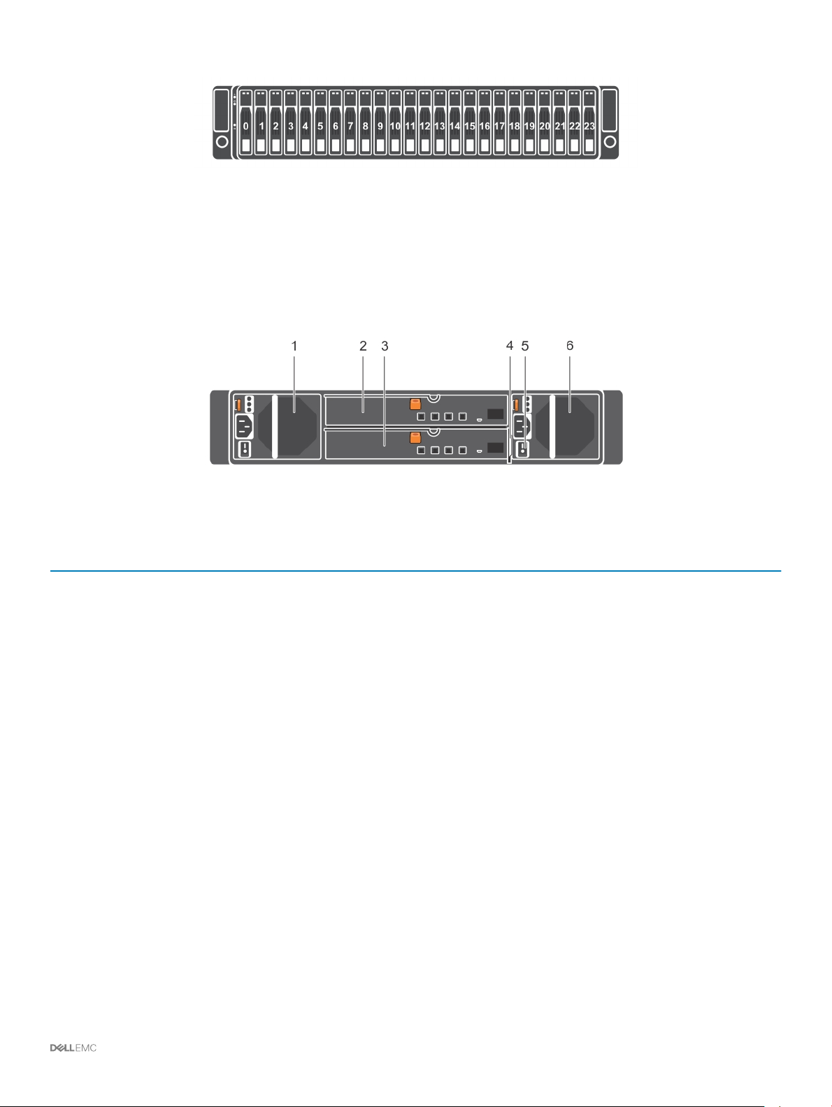
Figure 18. SCv320 Drive Numbering
SCv300 and SCv320 Expansion Enclosure Back-Panel Features and
Indicators
The back panel provides controls to power up and reset the expansion enclosure, indicators to show the expansion enclosure status, and
connections for back-end cabling.
Figure 19. SCv300 and SCv320 Expansion Enclosure Back Panel Features and Indicators
Item
1 Power supply unit and cooling fan
2 Enclosure management module (EMM 0)The EMM provides a data path between the expansion enclosure and the storage
3 Enclosure management module (EMM 1)The EMM provides a data path between the expansion enclosure and the storage
4 Information tag A slide-out label panel that records system information such as the Service Tag
5 Power switches (2) Controls power for the expansion enclosure. There is one switch for each power
6 Power supply unit and cooling fan
Name Description
600 W power supply
module (PS1)
controllers. The EMM also provides the management functions for the expansion
enclosure.
controllers. The EMM also provides the management functions for the expansion
enclosure.
supply.
600 W power supply
module (PS2)
About the SCv3000 and SCv3020 Storage System 25
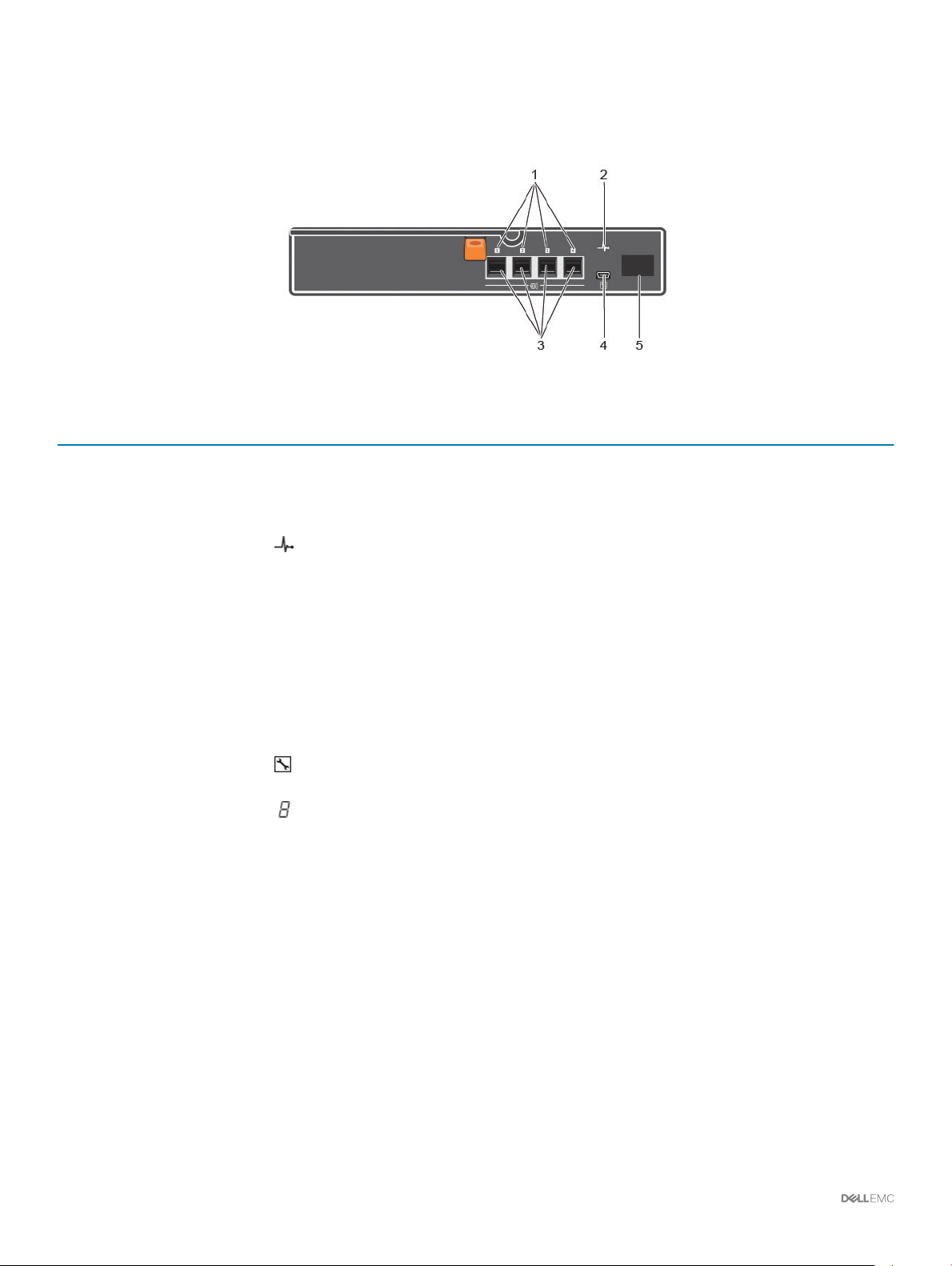
SCv300 and SCv320 Expansion Enclosure EMM Features and Indicators
The SCv300 and SCv320 expansion enclosure includes two enclosure management modules (EMMs) in two interface slots.
Figure 20. SCv300 and SCv320 Expansion Enclosure EMM Features and Indicators
Item Name Icon Description
1 SAS port status (1–
4)
• Green – All the links to the port are connected
• Amber – One or more links are not connected
• O – Expansion enclosure is not connected
2 EMM status
indicator
3 SAS ports 1–4
(Input or Output)
4 USB Mini-B (serial
debug port)
5 Unit ID display Displays the expansion enclosure ID
• On steady green – Normal operation
• Amber – Expansion enclosure did not boot or is not properly congured
• Blinking green – Automatic update in progress
• Blinking amber two times per sequence – Expansion enclosure is unable to
communicate with other expansion enclosures
• Blinking amber (four times per sequence) – Firmware update failed
• Blinking amber (ve times per sequence) – Firmware versions are dierent
between the two EMMs
Provides SAS connections for cabling the storage controller to the next expansion
enclosure in the chain. (single port, redundant, and multichain conguration).
Not for customer use
26 About the SCv3000 and SCv3020 Storage System
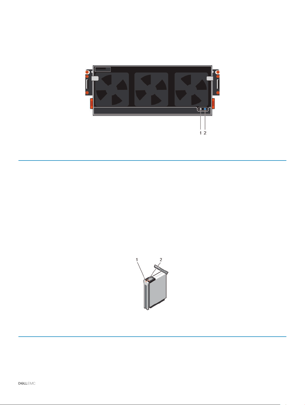
SCv360 Expansion Enclosure Front-Panel Features and Indicators
The SCv360 front panel shows the expansion enclosure status and power supply status.
Figure 21. SCv360 Front-Panel Features and Indicators
Item Name Description
1 Power LED The power LED lights when at least one power supply unit is supplying power to the expansion
enclosure.
2 Expansion enclosure status
LED
The expansion enclosure status LED indicates when the system is being identied or when the
expansion enclosure is in the fault state.
• O during normal operation.
• Blinks blue when a host server is identifying the expansion enclosure or when the system
identication button is pressed.
• Remains solid blue when the expansion enclosure is in the fault state.
SCv360 Expansion Enclosure Drives
Dell Enterprise Plus drives are the only drives that can be installed in SCv360 expansion enclosures. If a non-Dell Enterprise Plus drive is
installed, the Storage Center prevents the drive from being managed.
The drives in an SCv360 expansion enclosure are installed horizontally.
Figure 22. SCv360 Drive Indicators
Item
1 Drive activity indicator
Name Indicator Code
• Blinking blue – Drive activity
• Steady blue – Drive is detected and has no faults
2 Drive status indicator
• O – Normal operation
About the SCv3000 and SCv3020 Storage System 27
Item Name Indicator Code
• Blinking amber (on 1 sec. / o 1 sec.) – Drive identication is enabled
• Steady amber – Drive has a fault
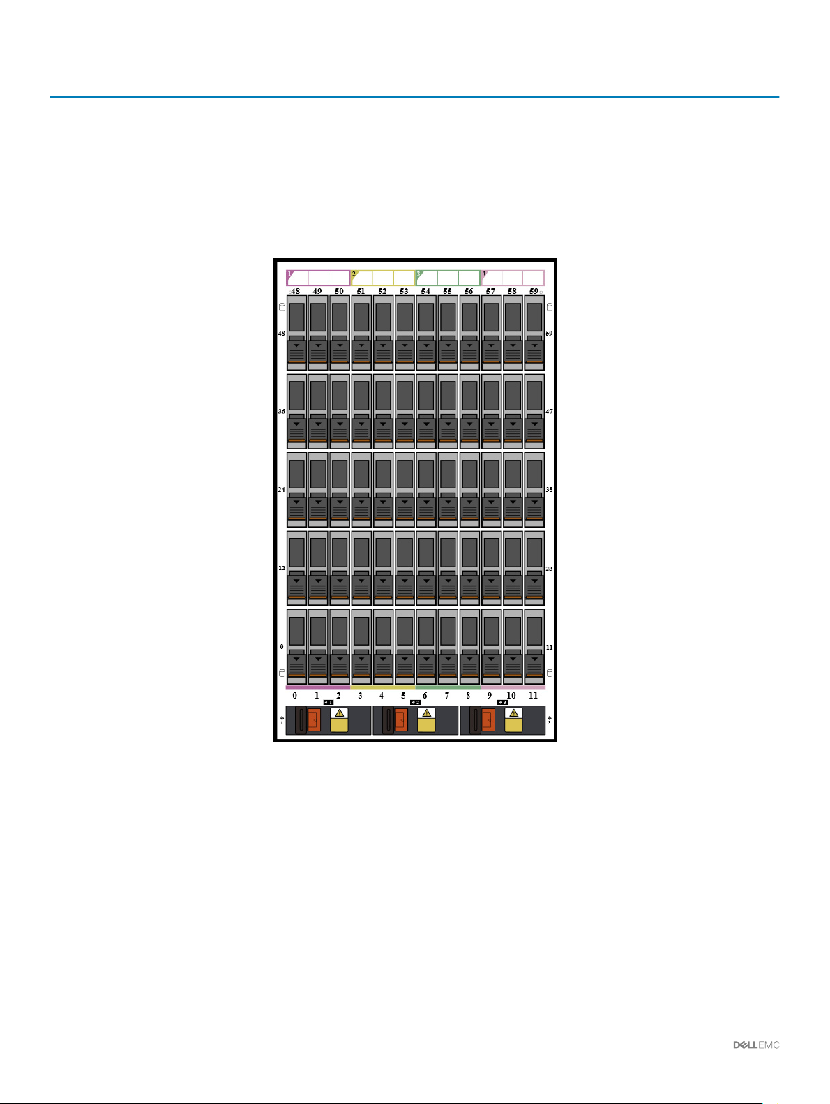
SCv360 Expansion Enclosure Drive Numbering
The Storage Center identies drives as XX-YY, where XX is the unit ID of the expansion enclosure that contains the drive, and YY is the
drive position inside the expansion enclosure.
An SCv360 holds up to 60 drives, which are numbered from left to right in rows starting from 0.
Figure 23. SCv360 Drive Numbering
28
About the SCv3000 and SCv3020 Storage System
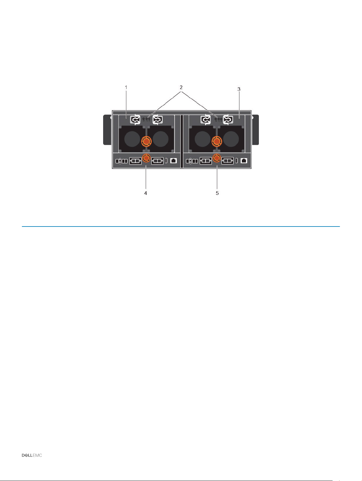
SCv360 Expansion Enclosure Back Panel Features and Indicators
The SCv360 back panel provides controls to power up and reset the expansion enclosure, indicators to show the expansion enclosure
status, and connections for back-end cabling.
Figure 24. SCv360 Back Panel Features and Indicators
Item
1 Power supply unit and
2 Power supply indicators
3 Power supply unit and
4 Enclosure management
5 Enclosure management
Name Description
cooling fan module (PS1)
• AC power indicator for
power supply 1
• Power supply/cooling
fan indicator
• AC power indicator for
power supply 2
cooling fan module (PS2)
module 1
module 2
Contains redundant 900 W power supplies and fans that provide cooling for the expansion
enclosure.
AC power indicators:
• Green: Normal operation. The power supply module is supplying AC power to the
expansion enclosure
• O: Power switch is o, the power supply is not connected to AC power, or has a fault
condition
• Flashing Green: AC power is applied but is out of spec.
Power supply/cooling fan indicator:
• Amber: Power supply/cooling fan fault is detected
• O: Normal operation
Contains redundant 900 W power supplies and fans that provide cooling for the expansion
enclosure.
EMMs provide the data path and management functions for the expansion enclosure.
EMMs provide the data path and management functions for the expansion enclosure.
About the SCv3000 and SCv3020 Storage System 29

SCv360 Expansion Enclosure EMM Features and Indicators
The SCv360 includes two enclosure management modules (EMMs) in two interface slots.
Figure 25. SCv360 EMM Features and Indicators
Item Name Description
1 EMM status indicator
• O – Normal operation
• Amber – fault has been detected
• Blinking amber two times per sequence – Expansion enclosure is unable to communicate
with other expansion enclosures
• Blinking amber (four times per sequence) – Firmware update failed
• Blinking amber (ve times per sequence) – Firmware versions are dierent between the
two EMMs
2 SAS port status indicator
3 Unit ID display Displays the expansion enclosure ID
4 EMM power indicator
5 SAS ports 1–4 (Input or
Output)
• Blue – All the links to the port are connected
• Blinking blue – One or more links are not connected
• O – Expansion enclosure is not connected
• Blue – Normal operation
• O – Power is not connected
Provides SAS connections for cabling the storage controller to the next expansion enclosure in
the chain (single port, redundant, and multichain conguration).
30 About the SCv3000 and SCv3020 Storage System
 Loading...