

Page 1

Dell Storage Center
SCv2080 Storage System
Getting Started Guide
Regulatory Model: E11J
Regulatory Type: E11J001
Page 2

Notes, Cautions, and Warnings
NOTE: A NOTE indicates important information that helps you make
better use of your computer.
CAUTION: A CAUTION indicates either potential damage to hardware or
loss of data and tells you how to avoid the problem.
WARNING: A WARNING indicates a potential for property damage,
personal injury, or death.
Copyright © 2016 Dell Inc. or its subsidiaries. All rights reserved. Dell, EMC, and other
trademarks are trademarks of Dell Inc. or its subsidiaries. Other trademarks may be
trademarks of their respective owners.
2016 - 12
Rev. A00
Page 3
Setting Up the Storage System
Consider the following best practices when setting up an SCv2080 storage system.
• Dell recommends that you use a dedicated SAN network for data transmission
when using a Fibre Channel or iSCSI storage system.
• Complete the Worksheet to Record System Information in this guide before
configuring the storage system.
• Always configure redundant data paths to provide alternate paths to and from
the host server should one of the data paths become disabled.
• Before connecting any cables between the storage system and host server or
expansion enclosure, physically label each port and connector.
• Always follow proper power-up and power-down procedures when cycling power
across the network. Verify that critical network components are on separate
power circuits.
NOTE: This product is intended for restricted access locations, such as a
dedicated equipment room or equipment closet.
WARNING: If installed in a closed or multi-unit rack assembly, the operating
ambient temperature of the rack environment may be greater than room
ambient temperature. Therefore, consideration should be given to installing
the equipment in an environment compatible with the maximum ambient
temperature (Tma) specified by the manufacturer.
Safety Warnings
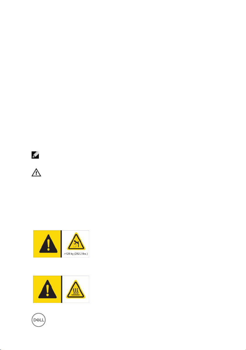
Heavy weight warning
A fully configured SCv2080 storage system weighs up
to 130 kg (287 lb). An unpopulated storage system
weighs 62 kg (137 lb). Use appropriate lifting methods
when installing the storage system.
High temperature warning
The operating temperature inside the drawers of a
storage system can reach up to 60°C (140°F). Take
3
Page 4
care when opening drawers and removing drive
carriers.
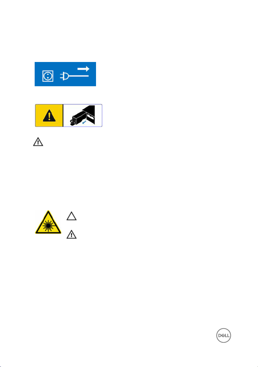
Electrical disconnection
Indicates that all electrical supply connections to the
storage system must be disconnected before
proceeding.
Battery pack warning
Remove the battery pack before removing a storage
controller from the storage system.
WARNING
explosion. Observe the following precautions:
• The battery should only be replaced with a battery that is the same or
• Do not attempt to open or service the battery. Do not dispose of the
Laser Radiation for Fibre Channel Storage Systems
The unit is certified in the U.S. to conform to the requirements of DHHS 21 CFR,
chapter 1 Subchapter J for Class I (1) laser products, and elsewhere is certified as a
Class I laser product conforming to the requirements of IEC 60825-1:2007.
Class I laser products are not considered to be hazardous. The laser system and unit
are designed so there is never any human access to laser radiation above a Class I
level during normal operation, user maintenance or prescribed service condition.
: Installing an incompatible battery may increase the risk of fire or
equivalent as the factory installed battery.
battery in a fire or with household waste. Contact the local waste disposal
agency for the location of the nearest battery deposit site.
CAUTION
to beam.
WARNING: Laser radiation, avoid direct exposure to beam.
: Class I laser radiation when open, avoid exposure
4
Page 5

Worksheet to Record System Information
Use the following worksheet to record the information that is needed to install the
SCv2080 storage system.
Storage Center Information
Gather and record the following information about the Storage Center network and
the administrator user.
Table 1. Storage Center Network
Service Tag ________________
Management IPv4 address (Storage Center management
address)
Left Controller IPv4 address (Controller 1 MGMT port) ___ . ___ . ___ . ___
Right Controller IPv4 address (Controller 2 MGMT port) ___ . ___ . ___ . ___
Subnet mask ___ . ___ . ___ . ___
Gateway IPv4 address ___ . ___ . ___ . ___
Domain name ________________
DNS server address ___ . ___ . ___ . ___
Secondary DNS server address ___ . ___ . ___ . ___
Table 2. Storage Center Administrator
Password for the default Storage Center “Admin” user ________________
Email address of the default Storage Center “Admin” user ________________
___ . ___ . ___ . ___
5
Page 6

iSCSI Fault Domain Information
For a storage system with iSCSI front-end ports, gather and record network
information for the iSCSI fault domains. This information is needed to complete the
Discover and Configure Uninitialized SCv2000 Series Storage Centers wizard.
NOTE: For a storage system deployed with two Ethernet switches, Dell
recommends setting up each fault domain on separate subnets.
See the Dell Storage Center SCv2080 Storage System Deployment Guide for
information about setting up iSCSI fault domains.
Table 3. iSCSI Fault Domain 1
Target IPv4 address ___ . ___ . ___ . ___
Subnet mask ___ . ___ . ___ . ___
Gateway IPv4 address ___ . ___ . ___ . ___
IPv4 address for storage controller module 1: port 1 ___ . ___ . ___ . ___
IPv4 address for storage controller module 2: port 1 ___ . ___ . ___ . ___
(Four port I/O card only) IPv4 address for storage
controller module 1: port 3
(Four port I/O card only) IPv4 address for storage
controller module 2: port 3
Table 4. iSCSI Fault Domain 2
Target IPv4 address ___ . ___ . ___ . ___
Subnet mask ___ . ___ . ___ . ___
Gateway IPv4 address ___ . ___ . ___ . ___
IPv4 address for storage controller module 1: port 2 ___ . ___ . ___ . ___
IPv4 address for storage controller module 2: port 2 ___ . ___ . ___ . ___
(4-port I/O card only) IPv4 address for storage controller
module 1: port 4
6
___ . ___ . ___ . ___
___ . ___ . ___ . ___
___ . ___ . ___ . ___
Page 7

(4-port I/O card only) IPv4 address for storage controller
module 2: port 4
___ . ___ . ___ . ___
Additional Storage Center Information
The Network Time Protocol (NTP) and Simple Mail Transfer Protocol (SMTP) server
information is optional. The proxy server information is also optional, but it may be
required to complete the Discover and Configure Uninitialized SCv2000 Series
Storage Centers wizard.
Table 5. NTP, SMTP, and Proxy Servers
NTP server IPv4 address ___ . ___ . ___ . ___
SMTP server IPv4 address ___ . ___ . ___ . ___
Backup SMTP server IPv4
address
SMTP server login ID ________________
SMTP server password ________________
Proxy server IPv4 address ___ . ___ . ___ . ___
___ . ___ . ___ . ___
Fibre Channel Zoning Information
For a storage system with Fibre Channel front-end ports, record the physical and
virtual WWNs of the Fibre Channel ports in Fault Domain 1 and Fault Domain 2. This
information is displayed on the Review Front-End page of the Discover and
Configure Uninitialized SCv2000 Series Storage Centers wizard. Use this
information to configure zoning on each Fibre Channel switch.
See the Dell Storage Center SCv2080 Storage System Deployment Guide for
information about setting up Fibre Channel zoning.
Table 6. Physical WWNs in Fault Domain 1
Physical WWN of storage controller 1: port 1 ________________
Physical WWN of storage controller 2: port 1 ________________
7
Page 8

(4-port I/O card only) Physical WWN of storage controller
1: port 3
________________
(4-port I/O card only) Physical WWN of storage controller
________________
2: port 3
Table 7. Virtual WWNs in Fault Domain 1
Virtual WWN of storage controller 1: port 1 ________________
Virtual WWN of storage controller 2: port 1 ________________
(4-port I/O card only) Virtual WWN of storage controller
________________
1: port 3
(4-port I/O card only) Virtual WWN of storage controller
________________
2: port 3
Table 8. Physical WWNs in Fault Domain 2
Physical WWN of storage controller 1: port 2 ________________
Physical WWN of storage controller 2: port 2 ________________
(4-port I/O card only) Physical WWN of storage
________________
controller 1: port 4
(4-port I/O card only) Physical WWN of storage
________________
controller 2: port 4
Table 9. Virtual WWNs in Fault Domain 2
Virtual WWN of storage controller 1: port 2 ________________
Virtual WWN of storage controller 2: port 2 ________________
(4-port I/O card only) Virtual WWN of storage controller
________________
1: port 4
(4-port I/O card only) Virtual WWN of storage controller
________________
2: port 4
8
Page 9

Locating Your Service Tag
Your storage system is identified by a unique service tag and Express Service Code.
You can find the service tag on the back of the storage system chassis. Dell uses this
information to route support calls to the appropriate personnel.
Figure 1. Service Tag Location
Other Information You May Need
To install the storage system, you may need the following additional information.
NOTE: See the safety and regulatory information that shipped with your
Storage Center components. Warranty information is included as a separate
document.
• The Dell Storage Center SCv2080 Storage System Deployment Guide provides
information about cabling storage system hardware components and configuring
a new storage system using the Dell Storage Manager Client.
• The Dell Storage Manager Storage Center Administrator's Guide describes how
to use the Dell Storage Manager Client to manage a Storage Center.
• The Dell Storage Manager Administrator’s Guide describes how to use Dell
Storage Manager to manage multiple Storage Center systems.
9
Page 10

Installation and Configuration
Before you begin installation, make sure that the site where you plan to install the
storage system has 208 V power from an independent source or a rack power
distribution unit with a UPS. (110 V power is not supported.)
In addition, verify that there is a 5U space in the lower 20U of the rack to install the
storage system. If you plan to install the storage system above the lower 20U of a
rack, a customer-provided mechanical lift must be used to avoid injury.
Safety Precautions
Always follow these safety precautions to avoid injury and damage to Storage Center
equipment.
If equipment described in this section is used in a manner not specified by Dell, the
protection provided by the equipment could be impaired. For your safety and
protection, observe the rules described in the following sections.
NOTE: See the safety and regulatory information that shipped with each
Storage Center component. Warranty information is included within this
document or as a separate document.
Installation Safety Precautions
Follow these safety precautions:
• Dell recommends that only individuals with rack-mounting experience install the
SCv2080 in a rack.
• You need at least two people to lift the storage system chassis from the shipping
box and three people to install it in the rack. The empty chassis weighs
approximately 62 kg (137 lbs).
• Make sure the storage system is always fully grounded to prevent damage from
electrostatic discharge.
• When handling the storage system hardware, use an electrostatic wrist guard
(not included) or a similar form of protection.
The chassis must be mounted in a rack. The following safety requirements must be
considered when the chassis is being mounted:
• The rack construction must be capable of supporting the total weight of the
installed chassis. The design should incorporate stabilizing features suitable to
10
Page 11

prevent the rack from tipping or being pushed over during installation or in normal
use.
• To avoid danger of the rack toppling over, slide only one chassis out of the rack at
a time.
• The storage system must be operated with low-pressure rear exhaust installation
(back pressure created by rack doors and obstacles not to exceed 5 Pascals [0.5
mm water gauge]).
Unpacking Storage Center Equipment
Unpack the storage system and identify the items in your shipment.
Figure 2. SCv2080 Storage System Components
1.
Hard Drives 2. Storage system
3. Rack rails (2) 4. Documentation
WARNING: Two people using lift straps are required to lift the storage
to avoid injury.
system
11
Page 12

Installing the Storage System in a Rack
Install the SCv2080 storage system and other Storage Center system components in
a rack.
NOTE: Mount the storage system in a manner that allows for expansion in
the rack and prevents the rack from becoming top‐heavy.
WARNING: If you plan to install the storage system above the lower 20U of
a rack, a customer-provided mechanical lift must be used to avoid injury.
1. Determine where to mount the storage system in the rack and mark the location
at the front and rear of the rack.
NOTE: The storage system and expansion enclosures each require 5U
of rack space for installation.
2. Position the rails at the marked locations and extend the rails to fit the rack.
3. Install the shelf and rails in the rack following the safety instructions and the rack
installation instructions provided with your rail kit.
Figure 3. Attach the Mounting Rails to the Rack
4. Slide the storage system chassis onto the rails until the rear of the array passes
through the rear hold-down brackets.
12
Page 13

Figure 4. Mount the SCv2080 Storage System Chassis
5. Secure the storage system chassis to the rails using mounting screws and by
bolting the rear hold-down brackets to the chassis.
6. Attach the plastic covers to the left and right side of the front of the storage
system chassis.
For more information about installing the storage system, see the Dell Storage
Center SCv2080 Storage System Deployment Guide.
7. If the Storage Center system includes an expansion enclosure, mount the
expansion enclosure above the storage system. For more information about
installing an expansion enclosure, see the Getting Started Guide included with
the expansion enclosure.
Installing the Hard Drives
Hard drives are connected to the backplane of the drawers using Disk Drive in Carrier
(DDIC) hard drive carriers.
The minimum number of drives for an SCv2080 storage system is 28, which is one
full, front row in the top drawer and one full, front row in the bottom drawer.
13
Page 14

Populate each row with identical drives. Do not mix types, speeds, or sizes in a single
row.
1. Open the top drawer.
CAUTION: If the storage system operates for too long (depending on
altitude) with a drawer open, the
causing a power failure and data loss. Such use may invalidate the
warranty.
a. Push and hold both drawer latches toward the center of the drawer.
b. Pull out the drawer all the way until it stops.
2. Populate the first row with 14 drives. Insert each disk drive in carrier (DDIC) into
the drawer, one at a time.
CAUTION: To maintain proper airflow, the drawers must be populated
with drives in whole rows (there are three rows of 14 drives per
drawer).
a. Hold the DDIC vertically and slide it most of the way into the slot.
b. Using both hands, apply downward pressure firmly and equally across the
DDIC.
c. While maintaining downward pressure on the DDIC, slide the top plate
toward the back of the drawer until it clicks in place.
storage system may overheat,
14
Page 15

Figure 5. Installing DDIC in Drawer
1.
DDIC 2. Top drawer
CAUTION: If the DDIC fails to latch, do not use it and request a
replacement from Dell Technical Support. If a faulty DDIC unlatches
within a closed drawer, it can make the drawer unable to be opened.
3. Close the drawer after inserting the DDICs.
a. Locate the two lock-release buttons situated midway along the runners on
each side of the drawer.
b. Press the lock-release buttons inward and use your body to push the drawer
toward the chassis until the locks disengage.
c. Place your hands on the front bezel and continue to push the drawer inward
until the bezel is flush with the chassis and the front drawer locks engage.
WARNING: Keep fingers clear of the chassis as the drawer is
closed.
15
Page 16

4. Repeat the previous steps for the bottom drawer, populating the first row with
14 drives.
5. To maintain proper airflow, populate the remaining rows in the following order:
a. Top drawer middle row
b. Bottom drawer middle row
c. Top drawer back row
d. Bottom drawer back row
Connecting the Power Cables
Connect the power cables to the storage system.
1. Before connecting the power cables, make sure that the power switches on the
storage system are in the OFF position.
2. Connect the power cables to the power supplies in the storage system chassis.
Figure 6. Power Cables
3. Secure each power cable to the storage system chassis using the strain relief
fasteners.
4. Plug the other end of the power cables into a grounded electrical outlet or a
separate power source such as an uninterrupted power supply (UPS) or a power
distribution unit (PDU).
16
Page 17

CAUTION: Be careful when closing the rear rack door to ensure that
power cords have adequate space as some racks might not be
sufficiently deep.
NOM Information (Mexico Only)
The following information is provided on the device described in this document in
compliance with the requirements of the official Mexican standards (NOM):
Importer
Model number E11J
Supply voltage 200–240 VAC
Frequency 50/60 Hz
Current
consumption
Dell Inc. de México, S.A. de C.V
Paseo de la Reforma 2620-11 ° Piso
Col. Lomas Atlas
11950 México, D.F.
16 A
Technical Specifications
The technical specifications for the SCv2080 storage system are shown in the
following tables.
Drives
SAS hard drives Up to 84 3.5-inch SAS hot-swappable hard drives (6.0 Gbps)
Storage Controllers
Storage controllers Two hot-swappable storage controllers with the following IO
options:
• Two 16 Gbps Fibre Channel ports
• Four 8 Gbps Fibre Channel ports
• Two 10 Gbps iSCSI ports
• Four 1 Gbps iSCSI ports
17
Page 18

Storage Controllers
• Four 12 Gbps SAS ports
Storage Connectivity
Configurations Storage Center supports up to 168 drives on a single
redundant-path SAS chain.
The SCv2080 storage system supports one SC180.
Redundant Array of Independent Disks (RAID)
Controller Two hot-swappable storage controllers
Management RAID management using Dell Storage Manager Client 2016 R2
Back-Panel Ports Connectors (per Storage Controller)
Fibre Channel,
iSCSI, or SAS
connectors
Ethernet
connectors
SAS connectors 6 Gbps SAS connectors for SAS port redundancy and an
USB Connector One USB 3.0 connector used for Storage Center updates
Serial connector
LED Indicators
Front panel
18
Connection to a Fibre Channel fabric, a iSCSI network, or a
direct connection to servers with SAS HBAs
MGMT: 1 Gbps or 10 Gbps embedded Ethernet/iSCSI port
that is typically used for Storage Center management
REPL: 1 Gbps or 10 Gbps embedded iSCSI port that is typically
used for replication to another Storage Center
additional expansion enclosure
NOTE: SAS connectors are SFF-8086/SFF-8088
compliant.
NOTE: Not for customer use.
• One two-digit LCD indicator for Unit ID, error code, and
unit location identifier
Page 19

LED Indicators
• One two-color LED indicator for power status
• One single-color LED indicator for module fault status
(enclosure as a whole)
• One single-color LED indicator for logical fault status
(drive, HBA, RAID controller, and so on)
• One single-color LED indicator for drawer 1 fault status
• One single-color LED indicator for drawer 2 fault status
Drawer
Disk Drive In Carrier
(DDIC)
6 Gb SAS IO
module
Cooling module
Power supply unit
(PSU)
Power Supplies
AC power supply (per power supply)
• One single-color LED indicator for sideplane card and
power status
• One single-color LED indicator for drawer fault status
• One single-color LED indicator for logical fault status
• One single-color LED indicator for cable fault status
• Six single-color LED indicators for data transfer status
One single-color LED for drive fault status
14 one-color LED status indicators, four each for the three
SAS ports and two for the module status
• One single-color LED indicator for module status
• One single-color LED indicator for battery fault status (not
currently used)
• One single-color LED indicator for fan fault status
• One single-color LED indicator for PSU fault status
• One single-color LED indicator for AC power fault status
• One single-color LED indicator for power status
Wattage 2.8 kW
Voltage 200–240 VAC (16 A)
Heat dissipation 191-147 W
19
Page 20

Power Supplies
Input frequency 50/60 Hz
Max input power 1791 VA
Input current 7.4 A@241 VAC
Maximum inrush
current
Available Hard Drive Power (per Slot)
Supported hard
drive power
consumption
(continuous)
I/O Card Power (per Slot)
Maximum power
consumed by I/O
card
Maximum available
power
Minimum available
power
Physical
Height 22.23 cm (8.8 inches)
Under typical line conditions and over the entire system
ambient operating range, the inrush current may reach 55 A
per power supply for 10 ms or less
Up to 1.16 A at +5 V
Up to 1.6 A at +12 V
11 W at +12 V
100 W at +12 V
1 W at +5 V (standby)
Width 48.26 cm (19 inches)
Depth (front
mounting bracket
to rear surface)
Depth (front
surface to rear
surface)
20
91.44 cm (36 inches)
96 cm (38 inches)
Page 21

Physical
Weight (maximum
configuration)
Weight without
drives
Environmental
For additional information about environmental measurements for specific storage
system configurations, see dell.com/environmental_datasheets.
Temperature
Operating 10°C to 35°C (50°F to 95°F) with a maximum temperature
Storage –40°C to 65°C (–40°F to 149°F) at a maximum altitude of
Relative humidity
Operating 10% to 80% (noncondensing) with 29°C (84.2°F) maximum
Storage 5% to 95% (noncondensing) with 33°C (91°F) maximum dew
130.1 kg (287 lb)
62.1 kg (137 lb)
gradation of 20°C per hour
NOTE: Maximum temperature of 35°C is reduced by
1°C per 300 meter (1°F per 547 feet) above 950
meters (3,117 feet)
12,000 m (39,370 ft)
dew point
point
Maximum vibration
Operating 0.21 G at 5–500 Hz for 15 min
Storage 1.04 G at 2–200 Hz for 15 min
Maximum shock
Operating Half-sine shock 5 G +/- 5% with a pulse duration of 10 ms +/-
10% (in operational orientations only)
Storage
• Z-axis: 30 g 10 ms half sine
• X- and Y-axes: 20 g 10 ms half sine
21
Page 22

Environmental
Altitude
Operating 0 m to 3048 m (0 ft to 10,000 ft)
Storage –300 m to 12,000 m (–1000 ft to 39,370 ft)
Airborne Contaminant Level
Class G2 or lower as defined by ISA-S71.04-1985
22
 Loading...