

Dell PowerEdge 180AS, PowerEdge 2160AS, PowerEdge 2161DS, PowerEdge 2321DS, PowerEdge KVM 1081AD User Manual
...
Dell™ Remote Console Switch
Software User’s Guide
Notes, Cautions, and Warnings
NOTE: A NOTE indicates important information that helps you make better
use of your computer.
CAUTION: A CAUTION indicates potential damage to hardware or loss
of data if instructions are not followed.
WARNING: A WARNING indicates a potential for property damage,
personal injury or death.
___________________
Information in this document is subject to change without notice.
© 2010 Dell Inc. All rights reserved.
1082DS/2162DS/4322DS Remote Console Switch

Third Party Software. You acknowledge that the SOFTWARE PRODUCT may contain or be provided
with copyrighted software of Dell's suppliers as identified in associated documentation or other printed
or electronic materials (“Third Party Software”) which are obtained under a license from such
suppliers. Your use of any such Third Party Software shall be subject to and you agree to comply with
the applicable restrictions and other terms and conditions set forth in such documentation or materials
as set forth in any “Third-Party Licenses ReadMe” file or similar file located in the installation directory
for the SOFTWARE PRODUCT.
Any open source software is distributed in the hope that it will be useful, but is provided “as is” without
any expressed or implied warranty; including but not limited to the implied warranty of merchantability
or fitness for a particular purpose. In no event shall Dell, the copyright holders, or the contributors be
liable for any direct, indirect, incidental, special, exemplary, or consequential damages (including, but
not limited to, procurement of substitute goods or services; loss of use, data or profits; or business
interruption) however caused and on any theory of liability, whether in contract, strict liability, or tort
(including negligence or otherwise) arising in any way out of the use of this software, even if advised
of the possibility of such damage.
Reproduction of these materials in any manner whatsoever without the written permission of Dell Inc.
is strictly forbidden.
Trademarks used in this text: Dell, the DELL logo, and Dell OpenManage are trademarks of Dell Inc.;
Intel Pentium is a registered trademark of Intel Corporation in the U.S. and other countries; Microsoft,
Windows, and Windows Vista are either trademarks or registered trademarks of Microsoft Corporation
in the United States and/or other countries; Avocent is a registered trademark of Avocent Corporation
or its affiliates in the US and other countries; Red Hat and Red Hat Enterprise Linux are registered
trademarks of Red Hat, Inc. in the United States and other countries; SUSE is a registered trademark
of Novell, Inc., in the United States and other countries; VMware is a registered trademark or trademark
(the “Marks”) of VMware, Inc. in the United States and/or other jurisdictions.
Other trademarks and trade names may be used in this document to refer to either the entities claiming
the marks and names or their products. Dell Inc. disclaims any proprietary interest in trademarks and
trade names other than its own.
590-1022-501A
August 2010
Model 1082DS/2162DS/4322DS Remote Console Switch

Contents iii
Contents
1 Product Overview . . . . . . . . . . . . . . . . . . 1
Features and Benefits . . . . . . . . . . . . . . . . . . . 1
Powerful Customization Capabilities
. . . . . . . . . 1
Extensive Remote Console Switch Management
. . 1
Authentication and Authorization
. . . . . . . . . . 2
System Components
. . . . . . . . . . . . . . . . . . . . 2
RCS Explorer Window
. . . . . . . . . . . . . . . . 2
Video Viewer
. . . . . . . . . . . . . . . . . . . . . 3
Interoperability with Avocent® Products . . . . . . 3
Operating Features. . . . . . . . . . . . . . . . . . . . . 4
Target Device Naming
. . . . . . . . . . . . . . . . 4
Target Device Name Displays . . . . . . . . . . . . 4
Sorting
. . . . . . . . . . . . . . . . . . . . . . . . 5
IPv4 and IPv6 Network Address Capabilities
. . . . . 5
2 Installation. . . . . . . . . . . . . . . . . . . . . . . . 7
Installing the Software . . . . . . . . . . . . . . . . 9
Uninstalling the Software
. . . . . . . . . . . . . . 10
Starting the Software
. . . . . . . . . . . . . . . . 10
Configuring Switches and Target Devices . . . . . 11
Web Interface Installation and Setup
. . . . . . . 13

iv Contents
3 Basic Software Operation . . . . . . . . . . . 15
Viewing Your System in the Explorer . . . . . . . . . . 15
Customizing the Window Display . . . . . . . . . . . . 17
Adding a Remote Console Switch (Dell or Avocent)
. . 17
Accessing Your Remote Console Switch
. . . . . . . . 25
Launching the VNC or RDP Viewer . . . . . . . . . . . 27
Changing Server and Switch Properties
. . . . . . . . 27
General Properties
. . . . . . . . . . . . . . . . . 27
Server Network Properties
. . . . . . . . . . . . . 29
Switch Network Properties . . . . . . . . . . . . . 29
Information Properties
. . . . . . . . . . . . . . . 30
Server Connections Properties
. . . . . . . . . . . 31
VNC Properties . . . . . . . . . . . . . . . . . . . 32
RDP Properties
. . . . . . . . . . . . . . . . . . . 33
Accessing a Server via a Browser Window
. . . . 34
Changing Server and Switch Options
. . . . . . . . . . 34
General Options
. . . . . . . . . . . . . . . . . . . 35
Default Browser
. . . . . . . . . . . . . . . . . . . 35
Changing DirectDraw Support (Windows OS Only) 36
HTTP/HTTPS Options
. . . . . . . . . . . . . . . . 37
VNC Options
. . . . . . . . . . . . . . . . . . . . . 37
RDP Options . . . . . . . . . . . . . . . . . . . . . 38
Organizing Your System . . . . . . . . . . . . . . . . . 38
Modifying Custom Field Names
. . . . . . . . . . . 40
Creating Folders. . . . . . . . . . . . . . . . . . . 41
Assigning a Unit to a Site, Location, or Folder
. . . 41
Deleting and Renaming
. . . . . . . . . . . . . . . 42
Customizing the Explorer Window
. . . . . . . . . . . 44

Contents v
Modifying the Selected View on Startup . . . . . . 44
Changing the Default Browser
. . . . . . . . . . . 45
Managing Your Local Databases
. . . . . . . . . . . . 45
Saving a Database
. . . . . . . . . . . . . . . . . 45
Loading a Database
. . . . . . . . . . . . . . . . . 46
Exporting a Database . . . . . . . . . . . . . . . . 46
4 Using the Viewer . . . . . . . . . . . . . . . . . . . 49
Accessing Servers from the RCS Software . . . . . . . 49
Interacting With the Server Being Viewed
. . . . . . . 51
Viewer Window Features
. . . . . . . . . . . . . . 52
Adjusting the Viewer
. . . . . . . . . . . . . . . . 54
Adjusting the Viewer Resolution . . . . . . . . . . 57
Adjusting the Video Quality
. . . . . . . . . . . . . 58
Minimizing Remote Video Session Discoloration
. 60
Improving Screen Background Color Display . . . 60
Setting Mouse Scaling
. . . . . . . . . . . . . . . 61
Minimizing Mouse Trailing
. . . . . . . . . . . . . 62
Improving Mouse Performance . . . . . . . . . . 62
Reducing Mouse Cursor Flickering
. . . . . . . . . 63
Viewing Multiple Servers Using the Scan Mode
. . 63
Scanning Your Servers . . . . . . . . . . . . . . . 63
Thumbnail View Status Indicators
. . . . . . . . . 65
Navigating the Thumbnail Viewer
. . . . . . . . . 66
Using Macros to Send Keystrokes to the Server . . 67
Session Options - General Tab
. . . . . . . . . . . 69
Screen Capturing
. . . . . . . . . . . . . . . . . . 70
Session Sharing Options
. . . . . . . . . . . . . . . . . 71
Automatic Sharing
. . . . . . . . . . . . . . . . . 71
Exclusive Mode
. . . . . . . . . . . . . . . . . . . 73

vi Contents
Stealth Connection . . . . . . . . . . . . . . . . . 75
Preemption Mode
. . . . . . . . . . . . . . . . . . 76
Virtual Media
. . . . . . . . . . . . . . . . . . . . . . . 78
Sharing and Preemption
. . . . . . . . . . . . . . 79
Launching Virtual Media
. . . . . . . . . . . . . . 80
Mapping Virtual Media Drives . . . . . . . . . . . 81
Virtual Media Connection Status
. . . . . . . . . . 82
Virtual Media Sessions
. . . . . . . . . . . . . . . 82
A Appendix A: Updating RCS Software . . . 87
B Appendix B: Keyboard and Mouse . . . . 89
C Appendix C: TCP Ports . . . . . . . . . . . . . . 93
D Appendix D: Technical Support . . . . . . . 95
Index . . . . . . . . . . . . . . . . . . . . . . . . . . . . . . . 97

Product Overview 1
1
Product Overview
The Dell™ Remote Console Switch (RCS) software is a cross-platform
management application that allows you to view and control the Dell Remote
Console Switch and all attached servers. The cross-platform design ensures
compatibility with most popular operating systems and hardware platforms.
The RCS software provides secure switch-based authentication, data
transfers, and username/password storage. Each switch handles
authentication and access control individually for more decentralized system
control.
The RCS software utilizes Explorer-like navigation with an intuitive splitscreen interface, providing you with a single point of access for your entire
system. From here, you can manage your existing switches, install a new
switch, or launch a video session to a system server. Built-in groupings such as
Servers, Sites, and Folders provide an easy way to select the units to view.
Powerful search and sort capabilities allow you to easily find any unit.
Features and Benefits
The RCS software is designed for easy installation and operation. Autodiscovery of managed switches enables you to install new units in minutes.
Wizard-based installation and online help simplify initial system
configuration. The intuitive graphical interface makes managing and
updating switches simple and straightforward.
Powerful Customization Capabilities
You can tailor the RCS software to fit your specific system needs. Take
advantage of built-in groups or create your own. Customize unit and field
names and icons for maximum flexibility and convenience. Using names that
are meaningful to you makes it easy to quickly find any system unit.
Extensive Remote Console Switch Management
The RCS software allows you to add and manage multiple switches in one
system. Once a new switch is installed, you can configure switch parameters,
control and preempt user video sessions, and execute numerous control

2 Product Overview
functions, such as rebooting and upgrading your switch. The RCS software is
designed to be compatible with the Dell OpenManage™ IT Assistant Event
Viewer, allowing system administrators to consolidate system event reports.
You can enable Simple Network Management Protocol (SNMP) traps,
configure target devices, and manage user databases.
You can use the software to manage the following Dell switches:
• 4322DS
• 2162DS
• 1082DS
• 2161DS
• 2321DS
• 4161DS
• 2161DS-2
Authentication and Authorization
The RCS software allows permissions for multiple Remote Console Switches
to be managed through a single interface rather than individually on each
Remote Console Switch. For increased security and efficiency, the
Lightweight Directory Access Protocol (LDAP) feature eliminates the need to
update access permissions in individual Remote Console Switches by drawing
permissions from a single network-wide authentication source.
The Remote Console Switch can authenticate using the standard Active
Directory schema, or the Dell Extended Schema in order to maximize
compatibility with all of your Dell hardware.
System Components
The software contains the following major components.
RCS Explorer Window
The RCS Explorer window is the primary point of control for accessing the
software features and functionality. From the Explorer window, you can view
the switches and target devices defined in the local database. Built-in
groupings such as Appliances and Devices provide different ways to list units.

Product Overview 3
You can create custom groups of units by adding and naming folders. Other
groupings are also available, based on custom fields that you can assign to
units.
From the Explorer Devices list, you can select a device from the list of target
devices and start a KVM session with the device. Starting a keyboard, video,
and mouse (KVM) session brings up a Video Viewer. From the Explorer
Appliances list, you can select a switch to configure.
Video Viewer
Users access and manage target devices through the Video Viewer. You can
use predefined macros and choose which macro group is displayed on the
Video Viewer Macros menu. You can open the Video Viewer to connect to
target devices on the Remote Console Switch. For more information, see
"Using the Viewer" on page 49.
The Video Viewer also provides access to the Virtual Media window. You can
use the Virtual Media window to map a physical drive such as a disk, CDROM, or DVD-ROM data drive, onto a target device so that the media device
is available to the target device even though it is not directly connected. For
more information on the Virtual Media window, see "Virtual Media" on
page 78.
Interoperability with Avocent
®
Products
The RCS software can also be used to manage some Avocent switches,
allowing increased flexibility in the management of systems
.
In addition, the RCS software includes support for Avocent IQ modules,
expanding the range of server types that can be managed. The addition of
support for Avocent IQ modules means that the following connections are
now supported:
• PS/2 modules (Dell and Avocent modules available)
• USB modules, including Virtual Media and Smart Card/Common
Access Card (CAC) versions (Dell and Avocent modules available)
• VT100 Serial modules (Avocent modules available)
• True Serial modules (Dell and Avocent modules available)
• Sun modules (Avocent modules available)
• PS2M modules (Avocent modules available)

4 Product Overview
NOTE: Dell SIP modules are supported on directly connected Avocent switches.
Operating Features
The RCS software features include target device naming, target device name
displays, sorting, and IPv4 and IPv6 network address capabilities. Appendix B:
Keyboard and Mouse lists the Explorer navigation shortcuts. Other
components also support full keyboard navigation in addition to mouse
operations.
Target Device Naming
The software requires that each switch and target device have a unique name.
To minimize the need for operator intervention, the software uses the
following procedure to generate a unique name for a target device whose
current name conflicts with another name in the database.
During background operations (such as an automated operation that adds or
modifies a name or connection), if a name conflict occurs, the conflicting
name is automatically made unique. This is done by appending a tilde (~)
followed by an optional set of digits. The digits are added in cases where
adding the tilde alone does not make the name unique. The digits start with a
value of one and are incremented until a unique name is created.
During operations, if you or another user specifies a non-unique name, a
message informs the corresponding user that a unique name is required.
Target Device Name Displays
When a switch is added, the target device names retrieved from the switch
are stored in the software database. The operator can then rename the target
device in the Explorer. The new name is stored in the database and used in
various component screens. This new target device name is not
communicated to the switch.
Since the software is a decentralized management system, you can change the
name assigned to a target device on the switch at any time without updating
the software database. Each operator can customize a particular view of the
list of target devices being managed.
Since you can associate more than one name with a single target device - one
on the switch and one in the software - the software uses the following rules
to determine which name is used:

Product Overview 5
• The Explorer only shows the target devices listed in its database, with
the name specified in the database. In other words, the Explorer does
not talk to the switch to obtain target device information.
• The Resync Wizard overwrites locally-defined target device names
only if the switch target device name has been changed from the
default value. Non-default target device names that are read from the
switch during a resynchronization override the locally-defined names.
Sorting
In certain displays, the software component displays a list of items with
columns of information about each item. If a column header contains an
arrow, you can sort the list by that column in ascending or descending order.
To sort a display by a column header, click the arrow in a column header. The
items in the list are sorted according to that column. An upward-pointing
arrow indicates the list is sorted by that column header in ascending order. A
downward-pointing arrow indicates the list is sorted by that column header in
descending order.
IPv4 and IPv6 Network Address Capabilities
The RCS software is compatible with systems using either of the currently
supported Internet Protocol Versions, IPv4 (default) or IPv6, or both the IPv4
and IPv6 modes simultaneously.
The IPv4 mode connection can be either a stateful (configuration and IP
addresses are provided by the server) or a stateless (the switch normally
receives the IP address and router address dynamically from the router) autoconfiguration. Switch firmware upgrades and emergency boot firmware
upgrades are supported for both TFTP and FTP servers while in IPv4 mode.
The IPv6 mode is a stateless, auto-configuration connection. While in IPv6
mode, switch firmware upgrades are only facilitated in FTP mode and
emergency boot firmware flash downloads cannot be performed. To perform a
flash download, you must temporarily connect to an IPv4 network with a
TFTP server.

6 Product Overview

Installation 7
2
Installation
Before you install the RCS software on a client computer, make sure that you
have all the required items and that the target devices and RCS client
computers are running the supported operating systems, browsers, and Java
Runtime Environment.
Supplied with the Software
The software is shipped with appliances on a Remote Console Switch
Software CD. The user documentation is available as an option on the Help
menu from the Remote Console Software Explorer window.
Supported Operating Systems
Client computers running the RCS must be running one of the following
operating system versions:
• Microsoft® Windows® 2003 Server with Service Pack 3 Web,
Standard, and Enterprise
• Microsoft Windows Server® 2008 Web, Standard, and Enterprise
• Microsoft Windows XP Professional with Service Pack 3
• Microsoft Windows Vista
™
Business with Service Pack 1
• Microsoft Windows 2000 Professional with Service Pack 4
• Microsoft Windows 7 Home Premium and Professional
• Red Hat® Enterprise Linux® 4.0 and 5.0 WS, ES, and AS
• SUSE® Linux Enterprise Server 10 and Server 11
• Ubuntu 8 Server and Workstation
Target devices must be running one of the following operating systems:
• Microsoft Windows 2000 Server (32-bit) and Advanced Server
• Microsoft Windows XP Professional and Standard with Service Pack 3
• Microsoft Windows Server 2003 Web, Standard, and Enterprise
• Microsoft Windows Server 2008 Web, Standard, and Enterprise

8 Installation
• Microsoft Windows Vista Standard, Business with Service Pack 1, and
Enterprise
• Microsoft Windows 7 Home Premium and Professional
• Netware 6.5 (32-bit)
• Red Hat Enterprise Linux 4.0 and 5.0 with WS, ES, and AS
• Solaris Sparc 10 (64-bit)
• SUSE Linux Enterprise Server 10 and Server 11
• Ubuntu 8 Server and Workstation
• VMware® ESX 3 and ESX 4 (32-bit)
Hardware Configuration Requirements
The software is supported on the following minimum computer hardware
configurations:
• 500 MHz Intel® Pentium® III
• 256 MB of RAM
• 10 or 100BaseT NIC (100 recommended)
• XGA Video with graphics accelerator
• Desktop size must be a minimum of 800 x 600
• Color palette must be a minimum of 65,536 (16-bit) colors
Supported Browsers
Computers used to access the Web interface and client computers running
the software must have one of the following browsers installed:
• Microsoft Internet Explorer version 6.x SPI or later
• Firefox version 2.0 or later
JRE Requirements
Computers used to access target devices using client computers running the
software must have Java Runtime Environment (JRE) 1.6.0_11 or higher
installed. The switch will attempt to detect if Java is installed on your PC. If
Java is not installed, download it from http:// www.java.com, then associate
the JNLP file with Java WebStart.

Installation 9
Installing the Software
The software can be installed on Microsoft Windows and Linux operating
systems. Follow these instructions to install RCS software on the desired
system.
To install on a Microsoft Windows system:
1
Insert the RCS software CD-ROM into your CD-ROM drive. If AutoPlay
is supported and enabled, the setup program will start automatically.
-or-
If your system does not support AutoPlay, set the default drive to your CDROM drive letter and execute the following command to start the install
program (replace “drive” with your CD-ROM drive letter):
drive:\WIN32\SETUP.EXE.
2
Follow the on-screen instructions.
To install on a Linux system:
1
Insert the RCS software CD-ROM into your CD-ROM drive.
2
If AutoMount is supported and enabled, proceed to step 3.
-or-
If your system does not support AutoMount:
Mount the CD-ROM volume by executing the following command:
mount -t iso9660 -ro mode=0555 <device> <mount point>
Replace “device” with the name of the CD-ROM on your machine and
mount point with the name of the desired mount point. For example, to
mount a CD-ROM which is the second IDE unit on /mnt, execute the
command:
mount -t iso9660 -ro mode=0555 /dev/hdb /mnt
3
At the command-line, execute the following command to change the
working directory to the mount point:
cd /mnt
4
Execute the following command to start the install program:
sh ./linux/setup.bin

10 Installation
5 Follow the on-screen instructions.
Uninstalling the Software
To uninstall the software on Microsoft Windows operating systems starting at
the Control Panel, complete the following steps:
1
Open the Control Panel and select
Add/Remove Programs
. A sorted list of
currently installed programs opens.
2
Select the RCS entry.
3
Click the
Change/Remove
button. The uninstall wizard starts.
4
Click the
Uninstall
button and follow the on-screen instructions.
To uninstall the software on Microsoft Windows operating systems using a
command window, complete the following steps:
1
Open a command window and change to the RCS install directory used
during installation. The default path for Windows 32-bit operating
systems is the program files directory.
2
Change to the UninstallerData subdirectory and enter the following
command (the quotation marks are required):
“Uninstall Dell Remote Console Software.exe”
The uninstall wizard starts. Follow the on-screen instructions.
To uninstall the software on Linux operating systems, complete the following
steps:
1
Open a command window and change to the RCS install directory used
during installation. The default path for Linux systems is /usr/lib.
2
Change to the UninstallerData subdirectory and enter the following
command:
% sh ./Uninstall_Dell_Remote_Console_Software
The uninstall wizard starts. Follow the on-screen instructions.
Starting the Software
To launch the software on Microsoft Windows systems:
Select Start - Programs - Dell RCS software. The RCS software will launch.
To launch the RCS software on Linux:

Installation 11
From the application folder (/usr/lib/Dell_Remote_Console_Switch_Software
by default), enter the following command:
./Dell_Remote_Console_Switch_Software
-or-
From (/user/bin), enter the following link:
./Dell_Remote_Console_Switch_Software
-or-
If the product was installed in a directory other than the default, then execute
the following command from a shell:
<path>/Dell_Remote_Console_Switch_Software
-or-
If a desktop shortcut was created on installation, double-click the shortcut.
Configuring Switches and Target Devices
This section provides an overview of configuration steps for the switch and for
user access to target devices. For switch-specific information, see the
Installation and User’s Guide for the switch.
To add switches, complete the following steps:
1
Install the software on one or more client computers.
2
Open the software on a client computer.
3
Use the Explorer to set unit properties, options, and other customization
as needed.
4
Configure the names of all target devices using the local GUI interface.
5
Repeat steps 3 through 6 for each switch you want to manage.
6
After one software environment is set up, select
File - Database - Save
to
save a copy of the local database with all the settings.
7
From the software on a second computer, select
File - Database - Load
and browse to find the saved file. Select the file and then click
Load
.
Repeat this step for each client computer that you want to setup.

12 Installation
8
To access a target device attached to an switch, select the target device in
the Explorer and click the
Connect Video
or
Browse
button to open a
session (only the corresponding button for the selected target device is
visible).
You can configure user accounts using the RCS software or through the
Remote Console Switch integrated Web interface. For more information see
the Dell Remote Console Switch Installation and User’s Guide.
To configure the Remote Console Switch, complete the following steps:
1
Connect a terminal or PC running the terminal emulation software to the
configuration port on the back panel of the switch using the supplied serial
cable. The terminal should be set to 9600 baud, 8 bits, 1 stop bit, no parity,
and no flow control.
2
Plug the supplied power cord into the back of the switch and then into an
appropriate power source.
3
When the power is switched on, the Power indicator on the rear of the unit
will blink for 30 seconds while performing a self-test. Press the <Enter>
key to access the main menu.
To configure the Remote Console Switch hardware:
1
You will see the
Main
menu with eleven options. Select option 1,
Network
Configuration
.
2
Select option 1 to set your network speed. Once you enter your selection,
you will be returned to the
Network Configuration
menu.
3
Select option 2 to open the
IP Configuration
menu.
4
Type the appropriate number to select one of the following types of IP
addresses:
1: None, 2: IPv4 Static, 3: IPv4 Dynamic, 4: IPv6 Static
, or 5:
IPv6 Dynamic
.
5
Select options 3-5 from the
Terminal Applications
menu, in turn, to finish
configuring your Remote Console Switch for IP address, Netmask, and
Default Gateway.
6
Once this is completed, type Ø to return to the main menu.
To configure the HTTP and HTTPS ports:
1
You will see the
Main
menu with eleven options. Select option 10,
Set
Web Interface Ports
to open the
Web Interface Port Configuration Menu
.

Installation 13
2
Select option 1 to set the port numbers. Type the port numbers you wish
to use for the HTTP port and the HTTPS port.
3
If the values are correct for your network, type <Y> and press the
<Enter> key.
4
At the local user station, input the target device names.
Mouse Acceleration
If you are experiencing slow mouse response during a remote video session,
deactivate mouse acceleration in the operating system of the target device
and adjust mouse acceleration on each target device to Slow or None.
Web Interface Installation and Setup
Once you have installed a new appliance, you can use the web interface to
configure unit parameters and launch video sessions.
Supported Browsers
The web interface supports the following browsers:
•
Microsoft Internet Explorer® version 6.x SP1 or later
•
Firefox version 2.0 or later
Launching the On-board Web Interface
To launch the web interface:
1
Open a web browser and type the IP address of the appliance using the
local Web interface.
NOTE: If you changed the default HTTP/HTTPS ports in the serial console and are
using an IPv4 address, use IP address format: https://<ipaddress>:<port#>, where
“port#” is the number you specified in the serial console. If you are using an IPv6
address, use format: https://[<ipaddress>]:<port#>, where “port#” is the number you
specified in the serial console. If you are using an IPv6 address, you must enclose
the address in square brackets.
2
The log in window opens. Type your username and password and click OK.
3
The web interface opens and displays the
Connections
tab.

14 Installation
NOTE: To use the Web interface, Java Runtime Environment (JRE) version 1.6.0_11
or higher must be installed on your computer. The KVM Switch will attempt to
detect Java on your PC. If Java is not installed, download it from
http://www.java.com, then associate the JNLP file with Java WebStart.
NOTE: Once you have logged in to the web interface, you will not have to log in
again when launching new sessions unless you have logged out or your session
has exceed the inactivity timeout specified by the administrator.

Basic Software Operation 15
3
Basic Software Operation
The RCS software Explorer (which is called Explorer from here on) is the
main GUI interface for the software. You can view, access, manage, and create
custom groupings for all supported units.
Viewing Your System in the Explorer
When you start the software, the main Explorer window opens. The Explorer
is divided into several panes: the View Selector tabs, the Group Selector
pane, and the Unit Selector pane. The content of these areas changes, based
on whether a target device or an appliance is selected or what task is to be
completed. Figure 3-1 highlights these navigation features.
Click one of the View Selector tabs to view your system organized by
categories: Remote Console Switches, Servers, Sites, or Folders. The
Explorer's default display is user-configurable. You can have it automatically
open to any one of these four tabs. For more information, see "Customizing
the Explorer Window" on page 44. If you do not customize the default
display, the Explorer will open to the Server view once you have added your
first Remote Console Switch.
16 Basic Software Operation
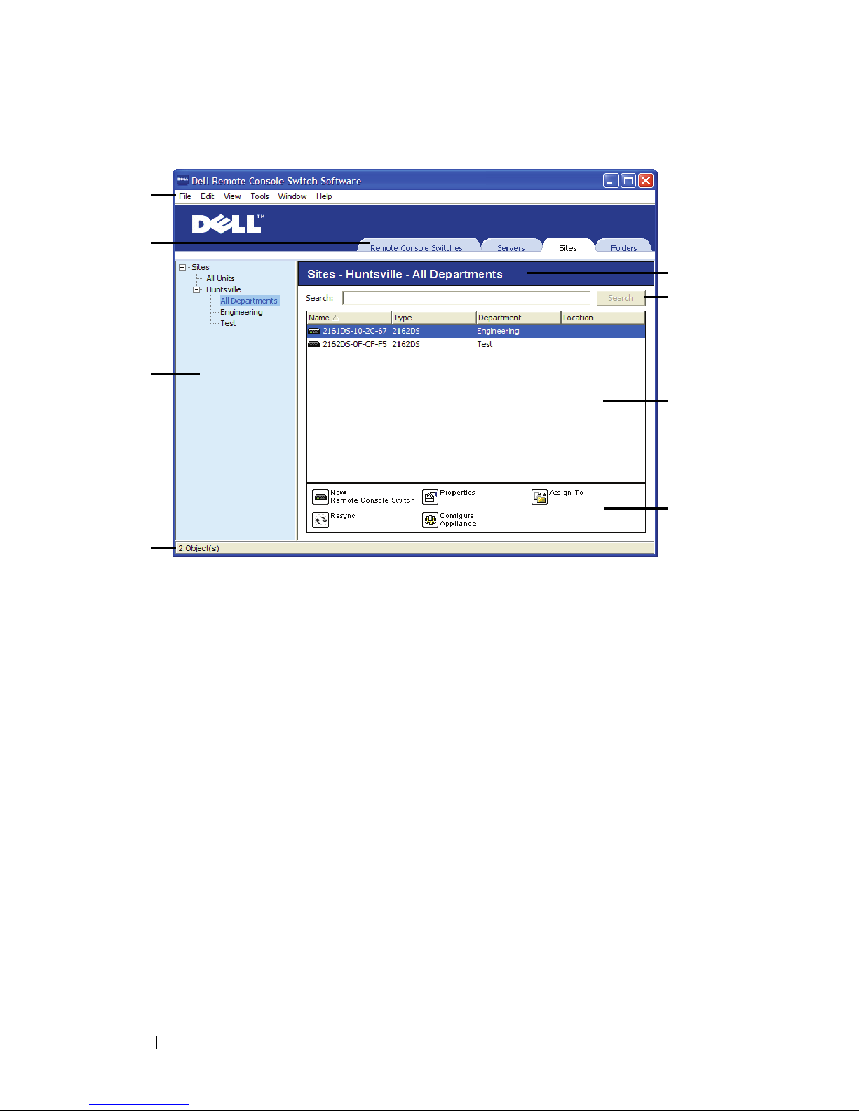
Figure 3-1. Explorer Window
1
Menu bar:
Allows you to access many of the features in the RCS software.
2
View Selector tabs:
Contains four
View Selector
tabs for choosing the
Explorer view.
3
Group Selector pane:
Contains a tree view representing the groups that
are available for the current
View Selector
tab. The selected group controls
what is displayed in the
Unit Selector
pane when the
Remote Console
Switches, Sites
or
Folder
tabs are selected.
4
Status bar:
Displays the number of units shown in the
Unit
list.
5
Unit Selector pane:
Contains the
Search
bar,
Unit
list, and
Ta sk
buttons
appropriate for the selected view or group.
6
Search bar:
Allows you to search the database based on the text entered in
the search box.
7
Unit list:
Displays a
Unit
list of units contained in the currently selected
group, or the results of the search executed from the
Search
bar.
1
2
3
4
5
6
7
8

Basic Software Operation 17
8
Task buttons:
Contains buttons representing tasks that can be executed.
Some buttons are dynamic based on the type of unit(s) selected in the
Unit
list while other buttons are fixed and always present.
If a selected switch is enabled for the Web interface, two additional buttons:
Resync and Configure Appliance appear at the bottom of the Explorer
window. The Resync button allows you to search for unpowered SIPs or
Avocent IQ modules. The Configure Appliance button allows you to upgrade
the Remote Console Switch. If a selected switch is not enabled for the Web
interface, the Resync and Configure Appliance buttons do not appear.
Customizing the Window Display
You can resize the Explorer window at any time. Each time you start the
application, the Explorer window opens to its default size and location.
A split-pane divider that runs from top to bottom separates the Group
Selector pane and the Unit Selector pane. You can move the divider left and
right to change the viewing area of these two panes. Each time the Explorer is
opened, the divider returns to its default location. See "Appendix B: Keyboard
and Mouse" on page 89 for divider pane and tree view control shortcuts.
You can specify which view (Appliances, Devices, Sites, or Folders) is visible
on startup or you can let the Explorer determine it. For more information, see
"Selected view on startup" on page 31.
You can change the order and sorting of the Unit list by clicking the sort bar
above the column. An upward-pointing arrow in a column header indicates
that the list is sorted by that field name in ascending order. A downwardpointing arrow indicates the list is sorted by that field name in descending
order.
Adding a Remote Console Switch (Dell or
Avocent)
In addition to the Dell Remote Console Switch, the RCS software can also be
used to manage Avocent switches. Therefore, as part of the process of adding
a Remote Console Switch to your RCS software database, you will be
prompted to select the vendor and product type for the switch you want to
18 Basic Software Operation
add. Once a Remote Console Switch or Avocent switch is added, it appears in
the Unit list. You may either manually add or discover a Remote Console
Switch. You may add a unit with either an IPv4 or an IPv6 address.
To add a new Remote Console Switch with an assigned IP address:
1
Select
File - New - Remote Console Switch
from the Explorer menu.
-or-
Click the
New Remote Console Switch
task button. The New Remote
Console Switch Wizard appears.
2
Click
Next
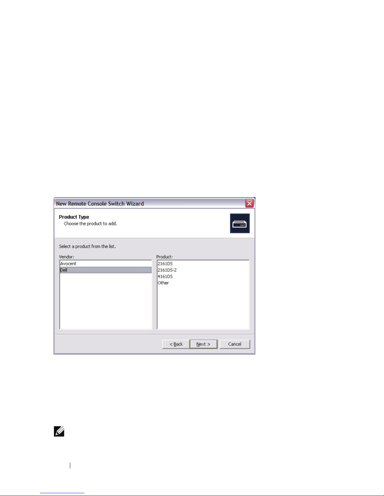
to continue. The
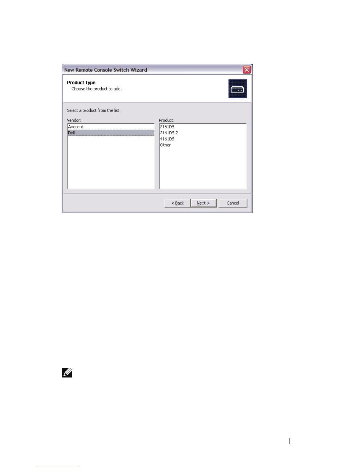
Product Type
dialog box appears and prompts
you to select the Remote Console Switch vendor and product.
Figure 3-2. Product Type Dialog Box
3
Select a
Ven do r
. For each vendor, the supported product names appear in
the
Product
list. Select a product.
If the Remote Console Switch model you wish to add is not available in
the
Product
list, select
Other
. Once this switch is discovered, it will be
available in the
Product
list the next time you add a Remote Console
Switch.
NOTE: Each dialog box in the New Remote Console Switch Wizard indicates the
type of switch you have selected from the Product list.

Basic Software Operation 19
4
Click
Next
.
5
You are prompted to indicate whether the Remote Console Switch has an
assigned IP address or not. Click
Yes
and then click
Next
.
6
The
Locate
window appears. Type the hostname or IP address, the HTTP
port, and the HTTPS port, and click
Next
. IPv4 addresses are entered in
xxx.xxx.xxx.xxx dot notation. IPv6 addresses are entered in hexadecimal
FD00:172:12:0:0:0:0:33 notation or compressed FD00:172:12::33 notation.
7
The RCS software searches for the indicated unit as well as all the powered
SIPs, Avocent IQ modules, and server names, if any. If you want to search
for unpowered SIPs or Avocent IQ modules, you can access the Resync
feature in the software and click to enable the
Include Offline SIPs
check
box.
8
Click
Next
.
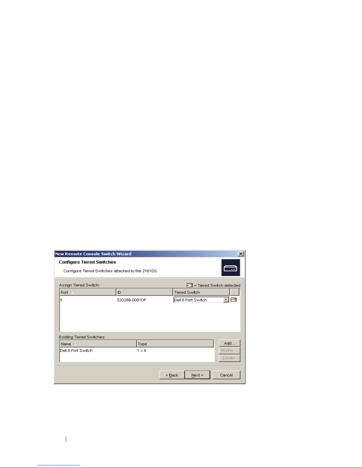
9 The Configure Tiered Switches dialog box appears if the RCS software
detects an attached legacy switch. This dialog box contains a list of all
SIP EIDs retrieved from the Remote Console Switch and the tiered
switches to which they are connected, if any. When this dialog box first
displays, all the switches will be set to None. Switches detected will have
an icon next to the drop-down list.
a
The
Existing Tiered Switches
field contains a list of all the current
switches defined in the database. Click
Add, Modify, or Delete
to
alter the list.
b
Associate the appropriate switch from the drop-down lists for each SIP
or Avocent IQ module that has a switch attached.
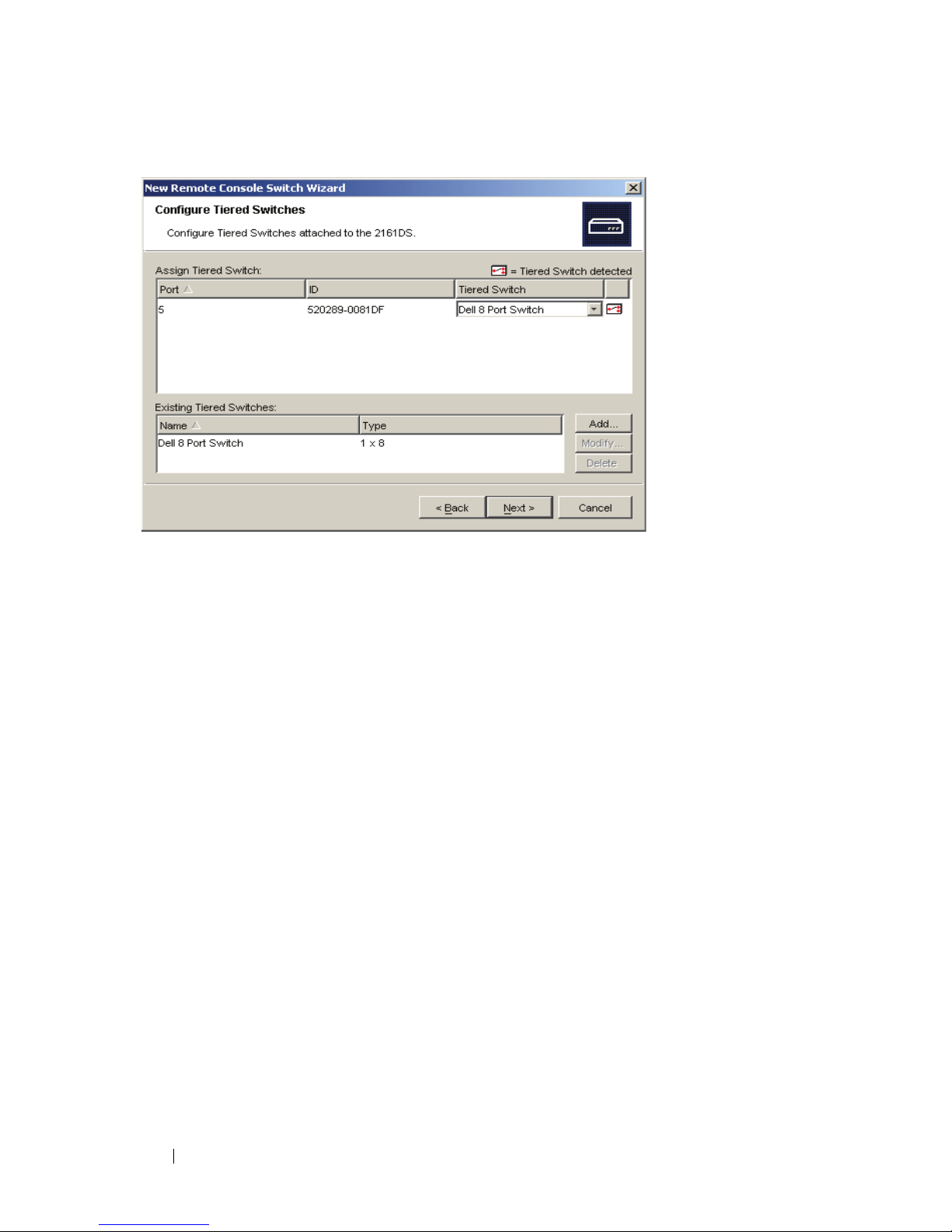
20 Basic Software Operation
Figure 3-3. Configure Tiered Switches Dialog Box
10
When you reach the final page of the
Remote Console Switch Wizard
,
click
Finish
to exit and return to the main window. Your Remote Console
Switch should now appear in the
Unit Selector
pane.
To add a new Remote Console Switch that does not have an assigned IP
address:
1
Select
File - New - Remote Console Switch
from the Explorer menu.
-or-
Click the
New Remote Console Switch
task button. The New Remote
Console Switch wizard appears.
2
Click
Next
to continue. The
Product Type
dialog box appears and prompts
you to select the Remote Console Switch vendor and product.
Basic Software Operation 21
Figure 3-4. Product Type Dialog Box
3
Select a
Vendor
. For each vendor, the supported product names appear in
the
Product
list. Select a product.
If the Remote Console Switch model you wish to add is not available in
the
Product
list, select
Other
. Once this switch is discovered, it will be
available in the
Product
list the next time you add a Remote Console
Switch.
4
Click
Next
.
5
You are prompted to indicate if the Remote Console Switch has an
assigned IP address. Click
No
and then click
Next
.
6
The
Network Address
window appears. Type the IP address, subnet mask
(if using IPv4 mode) or prefix length (if using IPv6 mode), and gateway
you wish to assign to the unit and click
Next
. IPv4 addresses are entered in
xxx.xxx.xxx.xxx dot notation. IPv6 addresses are entered in hexadecimal
FD00:172:12:0:0:0:0:33 notation or compressed FD00:172:12::33 notation.
NOTE: The Remote Console Switch supports DHCP (Dynamic Host Configuration
protocol) and static IP addressing. Dell recommends that IP addresses be reserved
for each unit and that they remain static while the Remote Console Switch units are
connected to the network.
22 Basic Software Operation
7
The
Select Remote Console Switch
window appears, prompting you to
select the unit to add from the list of new Remote Console Switches that
were found. Select the product and then click
Next
.
8
The
Configuring Remote Console Switch
window appears to indicate
whether the IP information was successfully configured. If the
configuration was successful, the software will search for the new Remote
Console Switch as well as all SIPs, Avocent IQ modules, and server names
associated with it. Click
Next
.
9
The
Configure Tiered Switches
dialog box appears if the software detects
an attached legacy switch. This dialog box contains a list of all SIP and
Avocent IQ module EIDs retrieved from the Remote Console Switch and
the tiered switches to which they are connected, if any.
a
The
Existing Tiered Switches
field contains a list of all the current
switches defined in the database. You may add to, delete, or modify
the list.
b
Associate the appropriate switch from the drop-down lists for each SIP
or Avocent IQ modules that has a switch attached.
Figure 3-5. Configure Tiered Switches Dialog Box
10
When complete, click
Finish
to exit the Wizard and return to the main
window. Your Remote Console Switch should now be in the
Unit Selector
pane.

Basic Software Operation 23
To discover a Remote Console Switch:
1
Select
Tools - Discover
from the Explorer menu from the software. The
Discover Wizard appears. Click
Next
to continue.
2
The
Address Range
page appears. Complete one of the following steps:
If you are using IPv4 mode, select
Use IPv4 address range
, and type the
range of IP addresses you wish to search on the network in the
To Add res s
and
From Address
boxes. IPv4 addresses are entered in xxx.xxx.xxx.xxx dot
notation.
- or -
If you are using IPv6 mode, select
Use IPv6 address range
, and type the
range of IP addresses you wish to search on the network in the
To Add res s
and
From Address
boxes. IPv6 addresses are entered in hexadecimal
FD00:172:12:0:0:0:0:33 notation or compressed FD00:172:12::33 notation.
3
You may also change the default HTTP and HTTPS port numbers, if the
Remote Console Switch has changed from the default on the serial
console, by typing the new port numbers in the
HTTP Port
and
HTTPS
Port
fields. Click
Next
to continue.
4
The
Searching Network
progress bar appears. Progress text indicates how
many addresses have been probed from the total number specified by the
range and the number of Remote Console Switches or Avocent switches
found. If one or more new Remote Console Switches or Avocent switches
are discovered, the Wizard shows the Select Remote Console Switches to
Add page. From this page, you can choose the Remote Console Switches
to add to the local database.
-or-
If no new Remote Console Switches were found (or if you clicked
Stop
),
the
Wizard
will show the
No New Remote Console Switches Found
page
and you will need to add the switch manually. For more information, see
the previous procedure.
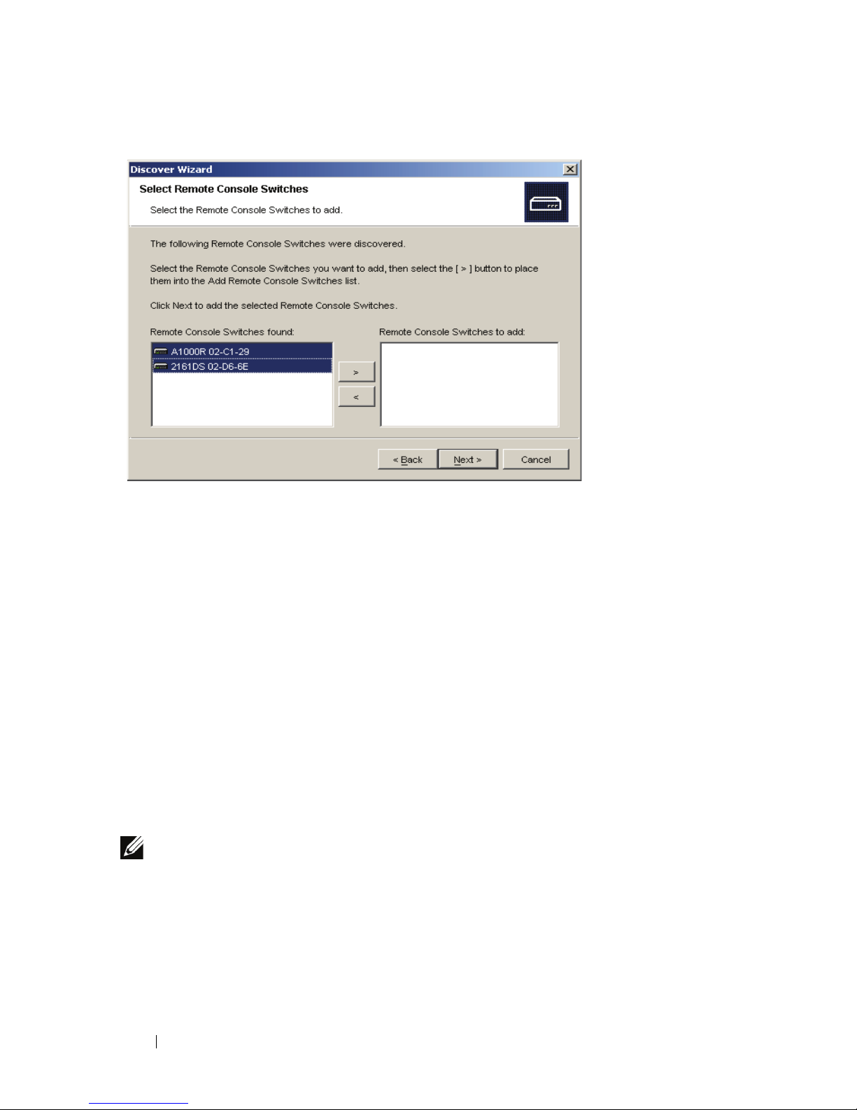
5
Click the Remote Console Switch(es) you wish to add and click the
Add
(>)
button to move the selection to the
Remote Console Switches to Add
list.
24 Basic Software Operation
Figure 3-6. Select Remote Console Switches to Add Dialog Box
6
Repeat step 5 for all Remote Console Switches you wish to add. Click
Next
to continue.
7
The
Adding Remote Console Switches
progress bar appears while the new
switches are being added. Once all of the selected switches have been
added to the local database, the
Discover Wizard Completed
page
appears. Click
Finish
to exit the Wizard and return to the main window.
Your new switches should now be in the
Unit Selector
pane.
8
If one or more switches could not be added to the local database for any
reason (including if you clicked
Stop
during the add process), the
Discover
Wizard
Not All Remote Console Switches Added
page appears. This page
will list all of the switches that you selected and the status for each. The
status will indicate if a Remote Console Switch was added to the local
database and if not, why the process failed. Click
Done
when you are
finished reviewing the list.
NOTE: If a Remote Console Switch already exists in the database with the same IP
address as a discovered unit, then the discovered switch will be ignored and will
not display on the next Wizard page.
 Loading...