

Page 1

Dell Remote Access Controller 4
Firmware Version 1.60 User’s Guide
Page 2

Notes and Notices
NOTE: A NOTE indicates important information that helps you make better use of
your computer.
NOTICE: A NOTICE indicates either potential damage to hardware or loss of data
and tells you how to avoid the problem.
____________________
Information in this document is subject to change without notice.
© 2007 Dell Inc. All rights reserved.
Reproduction in any manner whatsoever without the written permission of Dell Inc. is strictly
forbidden.
Trademarks used in this text: Dell, the DELL logo, Dell OpenManage, PowerEdge, and PowerVault
are trademarks of Dell Inc.; Microsoft, Active Directory, Internet Explorer, Windows, Windows NT,
Windows Server, and MS-DOS are registered trademarks and Windows V ista is a trademark of Microsoft
Corporation; Novell, NetWare, and SUSE are registered trademarks of Novell Corporation; Red Hat
is a registered trademark of Red Hat, Inc.; UNIX is a registered trademark of The Open Group in the
United States and other countries.
Copyright 1998-2005 The OpenLDAP Foundation. All rights reserved. Redistribution and use in source
and binary forms, with or without modification, are permitted only as authorized by the OpenLDAP
Public License. A copy of this license is availa ble in the f ile LICENSE in the top-level directory of the
distribution or, alternatively, at http://www.OpenLDAP.org/license.html. Ope nLDAP is a registered
trademark of the OpenLDAP Foundation. Individual files and/or contributed packages may be
copyrighted by other parties and subject to additional restrictions. This work is derived from the
University of Michigan LDAP v3.3 distrib ution. Information concerning this softw are is available at
http://www.umi ch.edu /~di rsvcs /ldap/ . This w ork also contains materials deriv ed from public sources.
Additional information about OpenLDAP can be obtained at http://www.openldap.org/. Portions
Copyright 1998-2004 Kurt D. Zeilenga. Portions Copyright 1998-2004 Net Boolean Incorporated.
Portions Copyright 2001-2004 IBM Corporation. All rights reserved. Redistribution and use in source
and binary forms, with or without modification, are permitted only as authorized by the OpenLDAP
Public License. Portions Copyright 1999-2003 Howard Y .H. Chu. Portions Copyright 1999-2003 Symas
Corporation. Portions Copyright 1998-2003 Hallvard B. Furuseth. All rights reserved. Redistribution
and use in source and binary forms, with or without modification, are permitted provided that this notice
is preserved. The names of the copyright holders may not be used to endorse or promote products derived
from this software without their specific prior written permission. This softw are is provided "as is'' without
express or implied warranty. Portions Copyright (c) 1992-1996 Regents of the Uni versity of Michig an.
All rights reserved. Redistribution and use in source and binary forms are permitted provided that this
notice is preserved and that due credit is given to the University of Michig an at Ann Arbor. The name
of the University may not be used to endorse or promote products derived from this software without
specific prior written permission. This software is provided "as i s'' without express or implied warranty .
Other trademarks and trade names may be used in this document to refer to either the entities claiming
the marks and names or their products. Dell Inc. disclaims any proprietary interest in trademarks and
trade names other than i ts own.
Other trademarks and trade names may be used in this document to refer to either the entities claiming
the marks and names or their products. Dell Inc. disclaims any proprietary interest in trademarks and
trade names other than its own.
September 2007 Rev. A00
Page 3

Contents
1 DRAC 4 Overview . . . . . . . . . . . . . . . . . . 15
What’s New In This DRAC 4 Release? . . . . . . . . . 15
DRAC 4 Hardware Features
. . . . . . . . . . . . . . . 16
Hardware Specifications . . . . . . . . . . . . . . . . 17
Power Requirements
. . . . . . . . . . . . . . . . 17
Connectors . . . . . . . . . . . . . . . . . . . . . 18
DRAC 4 Ports
Supported Remote Access Connections
. . . . . . . . . . . . . . . . . . . . 18
. . . . . . . . 19
DRAC 4 Security Features . . . . . . . . . . . . . . . . 19
Supported Platforms
Supported Operating Systems
Supported Web Browsers
. . . . . . . . . . . . . . . . . . 20
. . . . . . . . . . . . . . 20
. . . . . . . . . . . . . . . . 22
Supported Web Browsers for 64-Bit
Operating Systems
. . . . . . . . . . . . . . . . . 23
Disabling the Whitelist Feature in
Mozilla Firefox . . . . . . . . . . . . . . . . . . . 23
Features . . . . . . . . . . . . . . . . . . . . . . . . . 24
Other Documents You May Need
. . . . . . . . . . . . 25
Contents 3
Page 4

2 Installing and Setting Up the
DRAC 4 27
Before You Begin . . . . . . . . . . . . . . . . . . . . 27
Installing the DRAC 4 Hardware
Software Installation and Configuration Overview
Installing Your DRAC 4 Software
Configuring Your DRAC 4 Software
. . . . . . . . . . . . 27
. . . 28
. . . . . . . . . . 28
. . . . . . . . . 28
Registering the DRAC Host Name With
DNS Using DHCP . . . . . . . . . . . . . . . . . . 29
Installing the Software on the Managed System . . . . 29
Configuring the Managed System to
Capture the Last Crash Screen
. . . . . . . . . . . 30
Disabling the Windows Automatic
Reboot Option
. . . . . . . . . . . . . . . . . . . 31
Installing the Software on the Management
Station
. . . . . . . . . . . . . . . . . . . . . . . . . . 31
Installing the racadm CLI on a Red Hat
Enterprise Linux Management Station
. . . . . . . 32
Uninstalling the racadm CLI on a Red Hat
Enterprise Linux Management Station . . . . . . . 32
Configuring a Supported Web Browser . . . . . . . . . 33
Configuring Your Web Browser to Connect
to the Web-Based Interface
. . . . . . . . . . . . 33
Viewing Localized Versions of the Web-Based
Interface
. . . . . . . . . . . . . . . . . . . . . . 34
4 Contents
Installing the Sun Java Plug-In
Installing the Sun Java Plug-In to Use
Console Redirection
. . . . . . . . . . . . . . . . 34
Installing the Sun Java Plug-In to
Use Mozilla
. . . . . . . . . . . . . . . . . . . . . 35
. . . . . . . . . . . . . 34
Page 5

Configuring DRAC 4 Properties . . . . . . . . . . . . . 37
Configuring the DRAC 4 Network Settings
. . . . . . . 37
Configuring the DRAC 4 Network Settings
Using the Option ROM
Adding and Configuring DRAC 4 Users
Adding and Configuring SNMP Alerts
. . . . . . . . . . . . . . . 38
. . . . . . . . . 42
. . . . . . . . . 42
Updating the DRAC 4 Firmware . . . . . . . . . . . . . 42
Clearing the Web Browser Cache
With Internet Explorer
. . . . . . . . . . . . . . . 43
Clearing the Web Browser Cache
With Mozilla
Accessing the DRAC 4 Through a Network
. . . . . . . . . . . . . . . . . . . . 43
. . . . . . . 43
Accessing the DRAC 4 Using a
Supported Web Browser
. . . . . . . . . . . . . . 45
Accessing the DRAC 4 Using Server
Administrator . . . . . . . . . . . . . . . . . . . . 45
Accessing the DRAC 4 Using racadm CLI
. . . . . 45
DRAC 4 Software Basics for Red Hat
Enterprise Linux
. . . . . . . . . . . . . . . . . . . . . 45
Additional Information . . . . . . . . . . . . . . . . . 47
Removing the DRAC 4
. . . . . . . . . . . . . . . 47
Removing DRAC 4-Related Applications
and Drivers . . . . . . . . . . . . . . . . . . . . . 47
Contents 5
Page 6

3 Configuring the DRAC 4 to Use a Serial
or Telnet Text Console . . . . . . . . . . . . . . . 49
Serial and Telnet Console Features . . . . . . . . . . . 49
Enabling and Configuring the Managed System
to Use a Serial or Telnet Console
Configuring the System Setup Program on
the Managed System
Configuring Red Hat Enterprise Linux for
Serial Redirection During Boot
Enabling Login to the Console After Boot . . . . . 53
Enabling the Serial/Telnet Console
on the DRAC 4
. . . . . . . . . . . . . . . . . . . 56
Using the racadm Command to Configure
the Settings for the Serial and
Telnet Console . . . . . . . . . . . . . . . . . . . 57
. . . . . . . . . . . . 50
. . . . . . . . . . . . . . . . 50
. . . . . . . . . . . 51
6 Contents
Using the Secure Shell (SSH)
Enabling SSH
. . . . . . . . . . . . . . . . . . . . 59
Changing the SSH Port
. . . . . . . . . . . . . . 59
. . . . . . . . . . . . . . . 59
Supporting Cryptography Schemes . . . . . . . . 60
Connecting to the Managed System Through
the Local Serial Port or Telnet Management
Station (Client System)
Connecting the DB-9 Cable
. . . . . . . . . . . . . . . . . 61
. . . . . . . . . . . . . . . 61
Page 7

Configuring the Management Station Terminal
Emulation Software
. . . . . . . . . . . . . . . . . . . 62
Configuring Red Hat Enterprise Linux Minicom
for Serial Console Emulation
. . . . . . . . . . . . 63
Configuring HyperTerminal for Serial
Console Redirection . . . . . . . . . . . . . . . . 65
Configuring Red Hat Enterprise Linux XTerm
for Telnet Console Redirection
. . . . . . . . . . . 66
Enabling Microsoft Telnet for Telnet
Console Redirection . . . . . . . . . . . . . . . . 66
Using a Serial or Telnet Console
4 Managing and Recovering
a Remote System 69
Accessing the Web-Based Interface . . . . . . . . . . 69
Logging In
Adding and Configuring DRAC 4 Users
and Alerts
Adding and Configuring DRAC 4 Users
Configuring the DRAC 4 NIC
Adding and Configuring SNMP Alerts . . . . . . . 77
Managing a Remote System
Updating the DRAC 4 Firmware
Securing DRAC 4 Communications
Using SSL and Digital Certificates . . . . . . . . . 81
Viewing System Information
Recovering and Troubleshooting the
Managed System
First Steps to Troubleshoot a
Remote System
Managing Power on a Remote System
. . . . . . . . . . . . . . . . . . . . . 70
. . . . . . . . . . . . . . . . . . . . . . . . 71
. . . . . . . . . . . . . . 80
. . . . . . . . . . . . . . . . . . . . 89
. . . . . . . . . . . . . . . . . . . 89
. . . . . . . . . . . . 67
. . . . . . 71
. . . . . . . . . . . . 74
. . . . . . . . . . 80
. . . . . . . . . . . . 86
. . . . . . 90
Contents 7
Page 8

Using the SEL . . . . . . . . . . . . . . . . . . . . 91
Using the DRAC 4 Log . . . . . . . . . . . . . . . 92
Viewing the Last System Crash Screen
Using the Diagnostic Console
. . . . . . . . . . . 94
. . . . . . 93
Troubleshooting Network Problems . . . . . . . . 96
Troubleshooting Alerting Problems
. . . . . . . . 98
Frequently Asked Questions
. . . . . . . . . . . . . . 102
5 Using the DRAC 4 With Microsoft
Active Directory . . . . . . . . . . . . . . . . . . 105
Advantages and Disadvantages of Extended
Schema and Standard Schema . . . . . . . . . . . . . 105
Extended Schema Active Directory Overview
Active Directory Schema Extensions
Overview of the RAC Schema Extensions
Active Directory Object Overview
Configuring Active Directory to
Access Your DRAC 4 . . . . . . . . . . . . . . . . 111
Extending the Active Directory Schema . . . . . . 111
Using the Dell Schema Extender
Installing the Dell Extension to the Active
Directory Users and Computers Snap-In
Adding DRAC 4 Users and Privileges to
Active Directory
. . . . . . . . . . . . . . . . . . 119
Configuring the DRAC 4 with Extended
Schema Active Directory and
the Web-Based Interface . . . . . . . . . . . . . 121
Configuring the DRAC 4 with Extended
Schema Active Directory and
the racadm CLI
. . . . . . . . . . . . . . . . . . . 123
. . . . . 106
. . . . . . . 106
. . . . . 107
. . . . . . . . . 107
. . . . . . . . . . 112
. . . . . 117
8 Contents
Page 9

Standard Schema Active Directory Overview . . . . . 125
Configuring Standard Schema Active
Directory to Access Your DRAC 4
. . . . . . . . . 127
Configuring the DRAC 4 with Standard Schema
Active Directory and the racadm CLI
. . . . . . . 127
Enabling SSL on a Domain Controller
. . . . . . . . . 128
Exporting the Domain Controller
Root CA Certificate
. . . . . . . . . . . . . . . . . 129
Importing the DRAC 4 Firmware
SSL Certificate . . . . . . . . . . . . . . . . . . . 130
Using Active Directory to Log In to the DRAC 4
4096-Bit Key Encryption
. . . . . . . . . . . . . . 131
. . . . 131
Frequently Asked Questions . . . . . . . . . . . . . . 132
6 Using Console Redirection . . . . . . . . . . 135
Overview . . . . . . . . . . . . . . . . . . . . . . . . 135
Using Console Redirection
Keyboard, Video, and Mouse Encryption
Opening a Console Redirection Session
Frequently Asked Questions
. . . . . . . . . . . . . . . 135
. . . . . 136
. . . . . . 136
. . . . . . . . . . . . . . 139
7 Configuring and Using Virtual Media . . 147
Overview . . . . . . . . . . . . . . . . . . . . . . . . 147
Installing the Virtual Media Plug-In
Windows-Based Management Station
Linux-Based Management Station
. . . . . . . . . . 149
. . . . . . 149
. . . . . . . . 149
Contents 9
Page 10

Using the Virtual Media Feature . . . . . . . . . . . . 150
Booting From the Virtual Media
. . . . . . . . . . 150
Installing Operating Systems Using
Virtual Media . . . . . . . . . . . . . . . . . . . . 151
Using Virtual Media When the Server’s
Operating System Is Running . . . . . . . . . . . . 152
Enabling and Disabling the Virtual
Media Feature
. . . . . . . . . . . . . . . . . . . . . . 152
Configuring the Virtual Floppy Feature For
Your Operating System
. . . . . . . . . . . . . . . . . 153
Configuring the Virtual Floppy Feature as
a Super Floppy
. . . . . . . . . . . . . . . . . . . 154
Configuring the Virtual Floppy as
a Hard Drive . . . . . . . . . . . . . . . . . . . . 154
Frequently Asked Questions . . . . . . . . . . . . . . 155
8 Using the Serial and racadm
Commands . . . . . . . . . . . . . . . . . . . . . . . 163
Using a Serial or Telnet Console . . . . . . . . . . . . 163
Logging into the DRAC 4
Starting a Text Console
Viewing a List of Serial/Telnet Commands
. . . . . . . . . . . . . . 163
. . . . . . . . . . . . . . . 164
. . . . . 164
10 Contents
Using the racadm CLI
racadm Command Description
racadm Synopsis
. . . . . . . . . . . . . . . . . . 166
. . . . . . . . . . . 166
. . . . . . . . . . . . . . . . . . 167
racadm Options . . . . . . . . . . . . . . . . . . . 168
racadm Subcommand Descriptions
racadm Error Messages
. . . . . . . . . . . . . . 171
. . . . . . . . 169
Page 11

Configuring Multiple DRAC 4s . . . . . . . . . . . . . 171
Configuration File Overview
. . . . . . . . . . . . 171
Creating a DRAC 4 Configuration File . . . . . . . 172
Configuration File Example
. . . . . . . . . . . . . 176
Using the racadm Utility to Configure
the DRAC 4
. . . . . . . . . . . . . . . . . . . . . . . . 177
Before Adding a DRAC 4 User
. . . . . . . . . . . 177
Adding a DRAC 4 User Without
Alert Capabilities . . . . . . . . . . . . . . . . . . 178
Adding a DRAC 4 User With
Alerting Capabilities
. . . . . . . . . . . . . . . . 179
Adding a DRAC 4 User With Permissions . . . . . 181
Configuring DRAC 4 Network Properties
. . . . . 181
Frequently Asked Questions
. . . . . . . . . . . . . . 182
9 Troubleshooting . . . . . . . . . . . . . . . . . . 185
Troubleshooting the DRAC 4 . . . . . . . . . . . . . . 185
A racadm Subcommand Man Pages . . . . 187
help . . . . . . . . . . . . . . . . . . . . . . . . . . . 187
. . . . . . . . . . . . . . . . . . . . . . . . . . . . 188
arp
clearasrscreen
config/getconfig . . . . . . . . . . . . . . . . . . . . . 189
coredump
coredumpdelete
fwupdate
. . . . . . . . . . . . . . . . . . . . . 188
. . . . . . . . . . . . . . . . . . . . . . . . 193
. . . . . . . . . . . . . . . . . . . . . 195
. . . . . . . . . . . . . . . . . . . . . . . . . 195
Contents 11
Page 12

getssninfo . . . . . . . . . . . . . . . . . . . . . . . . 200
getsysinfo
getractime
. . . . . . . . . . . . . . . . . . . . . . . . 201
. . . . . . . . . . . . . . . . . . . . . . . . 204
ifconfig . . . . . . . . . . . . . . . . . . . . . . . . . . 205
. . . . . . . . . . . . . . . . . . . . . . . . . . 205
netstat
. . . . . . . . . . . . . . . . . . . . . . . . . . . 206
ping
setniccfg/getniccfg . . . . . . . . . . . . . . . . . . . 206
getsvctag
racdump
. . . . . . . . . . . . . . . . . . . . . . . . . 208
. . . . . . . . . . . . . . . . . . . . . . . . . 208
racreset . . . . . . . . . . . . . . . . . . . . . . . . . 209
racresetcfg
serveraction
getraclog
. . . . . . . . . . . . . . . . . . . . . . . . 211
. . . . . . . . . . . . . . . . . . . . . . . 212
. . . . . . . . . . . . . . . . . . . . . . . . . 213
clrraclog . . . . . . . . . . . . . . . . . . . . . . . . . 214
. . . . . . . . . . . . . . . . . . . . . . . . . . 214
getsel
12 Contents
. . . . . . . . . . . . . . . . . . . . . . . . . . . 215
clrsel
gettracelog . . . . . . . . . . . . . . . . . . . . . . . . 216
. . . . . . . . . . . . . . . . . . . . . . . . . . 216
setrac
sslcsrgen
sslcertupload
sslcertdownload
. . . . . . . . . . . . . . . . . . . . . . . . . 218
. . . . . . . . . . . . . . . . . . . . . . 220
. . . . . . . . . . . . . . . . . . . . . 221
Page 13

sslcertview . . . . . . . . . . . . . . . . . . . . . . . 222
testemail
testtrap
. . . . . . . . . . . . . . . . . . . . . . . . . 224
. . . . . . . . . . . . . . . . . . . . . . . . . . 225
vmdisconnect . . . . . . . . . . . . . . . . . . . . . . 225
B DRAC 4 Property Database Group
and Object Definitions . . . . . . . . . . . . . 227
idRacInfo . . . . . . . . . . . . . . . . . . . . . . . . 227
cfgLanNetworking
cfgCurrentLanNetworking
cfgRemoteHosts . . . . . . . . . . . . . . . . . . . . . 236
cfgUserAdmin
cfgTraps
. . . . . . . . . . . . . . . . . . . . . . . . . 242
cfgSessionManagement
cfgSerial . . . . . . . . . . . . . . . . . . . . . . . . . 246
. . . . . . . . . . . . . . . . . . . 229
. . . . . . . . . . . . . . . 234
. . . . . . . . . . . . . . . . . . . . . . 238
. . . . . . . . . . . . . . . . 244
cfgNetTuning
cfgOobSnmp
. . . . . . . . . . . . . . . . . . . . . . 251
. . . . . . . . . . . . . . . . . . . . . . . 257
cfgRacTuning . . . . . . . . . . . . . . . . . . . . . . 258
ifcRacManagedNodeOs
cfgRacSecurity
cfgRacVirtual
. . . . . . . . . . . . . . . . . . . . . . 266
cfgActiveDirectory
. . . . . . . . . . . . . . . . . 262
. . . . . . . . . . . . . . . . . . . . . 263
. . . . . . . . . . . . . . . . . . . 267
Contents 13
Page 14

cfgStandardSchema . . . . . . . . . . . . . . . . . . . 271
Event Filter Operation and Event Mask Properties
DRAC 4-Generated Event Mask Definitions
. . . 273
. . . . . . . 273
System-Generated Alert Mask Definitions . . . . . . . 275
Alert Filter Properties
Alert Test Commands
. . . . . . . . . . . . . . . . . . 276
. . . . . . . . . . . . . . . . . . 276
Glossary . . . . . . . . . . . . . . . . . . . . . . . . . . . 279
Index . . . . . . . . . . . . . . . . . . . . . . . . . . . . . . 287
14 Contents
Page 15

1
DRAC 4 Overview
The Dell™ Remote Access Controller 4 (DRAC 4) is a systems management
hardware and software solution designed to provide remote management
capabilities, crashed system recovery, and power control functions for Dell
PowerEdge™ systems.
By communicating with the system’s baseboard management controller
(BMC), the DRAC 4 can be configured to send you email alerts for warnings
or errors related to voltages, temperatures, and fan speeds. The DRAC 4 also
logs event data and the most recent crash screen (for systems running the
Microsoft
probable cause of a system crash.
Depending on your system, the DRAC 4 hardware is either a daughter card
(DRAC 4/I) or a half-length PCI card (DRAC 4/P). The DRAC 4/I and DRAC
4/P are identical except for the hardware differences (see "DRAC 4 Hardware
Featu re s" ).
The DRAC 4 has its own microprocessor and memory, and is powered by the
system in which it is installed. The DRAC 4 may be preinstalled on your
system, or available separately in a kit.
To get started with the DRAC 4, see "Installing and Setting Up the DRAC 4."
®
Windows® operating system only) to help you diagnose the
What’s New In This DRAC 4 Release?
For this release, the DRAC 4 firmware version 1.60:
• Supports Microsoft Windows Server® 2008.
• Supports an option to allow users to specify LDAP or Global Catalog
servers to handle user authentication.
• Provides the ability to specify a list of LDAP servers and Global Catalog
servers.
DRAC 4 Overview 15
Page 16
• Supports a new macro—<RightCtrl>+<ScrlLock><ScrlLock> key
code sequence to initiate a crash dump of the Microsoft Windows
operating system. For more information, see the Microsoft Knowledge
Base at:
• Provides DRAC 4/P support on the Dell PowerVault™ 100.
http://support.microsoft.com/kb/256986/
NOTE: You must keep the <RightCtrl> key pressed during the additional
keystrokes.
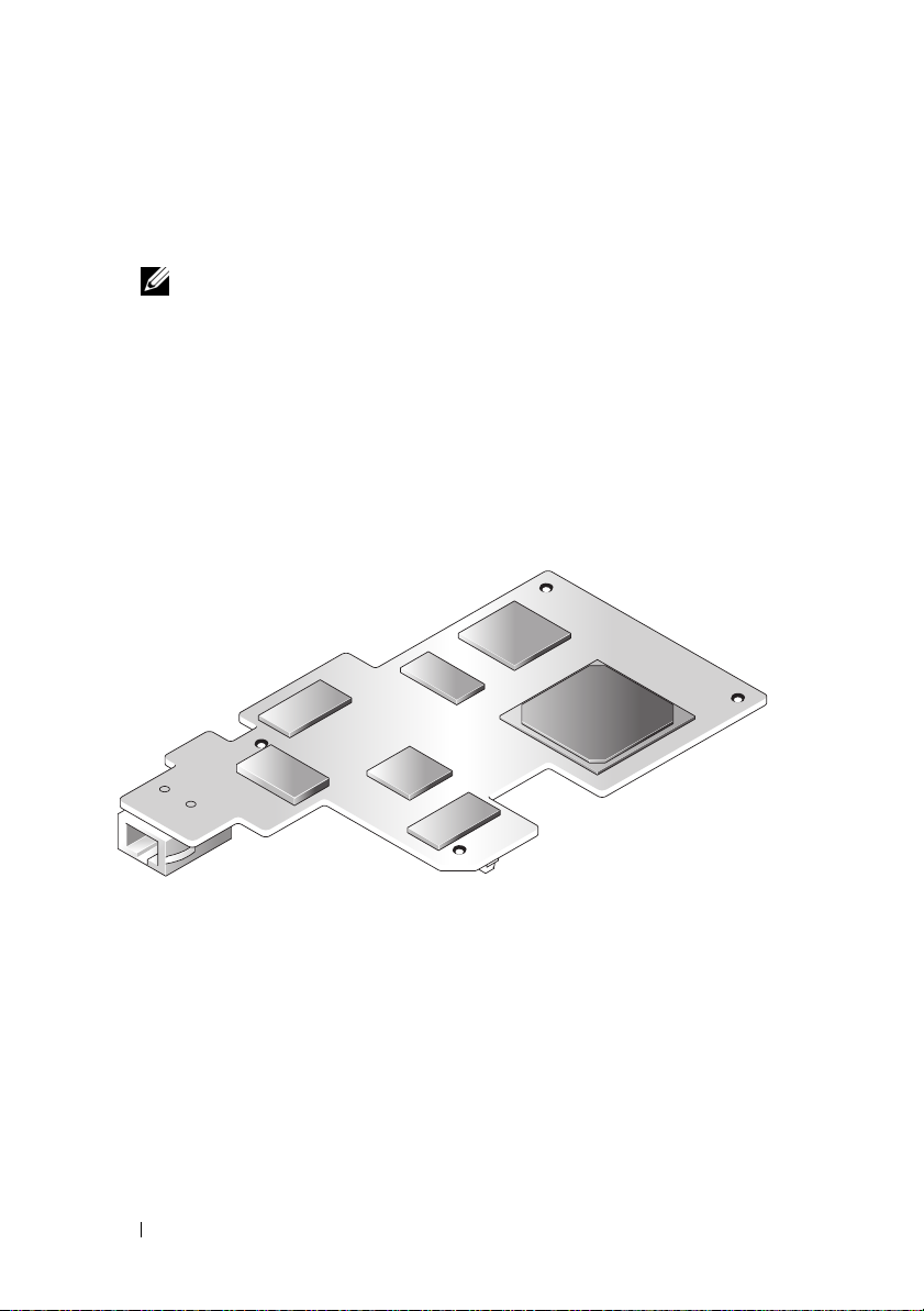
DRAC 4 Hardware Features
Figure 1-1 shows the DRAC 4/I hardware features and Figure 1-2 shows the
DRAC 4/P hardware features.
Figure 1-1. DRAC 4/I Hardware Features
RJ-45 Connector
16 DRAC 4 Overview
Page 17
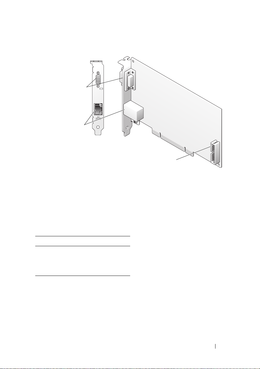
Figure 1-2. DRAC 4/P Hardware Features
Video Connector
RJ-45 Connector
Management Connector
Hardware Specifications
Power Requirements
Table 1-1 lists the power requirements for the DRAC 4.
Table 1-1. DRAC 4 Power Requirements
System Power
1.2 A on +3.3 V AUX (maximum)
550 mA on +3.3 V main (maximum)
0 mA on+5V main (maximum)
DRAC 4 Overview 17
Page 18

Connectors
NOTE: The DRAC 4 hardware installation instructions are located in the Installing a
Remote Access Card document or the Installation and Troubleshooting Guide
included with your system. Ensure that you connect the management cable and the
local video monitor (if present) to the DRAC 4/P in PCI slot 4.
The DRAC 4 provides a dedicated 10/100 Mbps RJ-45 NIC and a connector
for mounting the card to the system board. The DRAC 4/P also provides a
video connector, and a 30-pin Management Connector.
DRAC 4 Ports
Table 1-2 identifies the ports used by the DRAC 4. This information is
required when opening firewalls for remote access to a DRAC 4.
Table 1-2. DRAC 4 Port Numbers
DRAC 4 Port Number Used For
Ports on DRAC 4 listening for connection (server):
22
23
80
161
443
3668
5869
5900
Ports that DRAC 4 uses as a client:
25
53
68
69
162
636
3269
Secure Shell (configurable)
Telnet (configurable)
HTTP (configurable)
SNMP Agent (not configurable)
HTTPS (configurable)
Virtual Media server (configurable)
Remote racadm spcmp server (not configurable)
Console Redirection (configurable)
SMTP (not configurable)
DNS (not configurable)
DHCP-assigned IP address
TFTP (not configurable)
SNMP trap (not configurable)
LDAP (not configurable)
LDAP for global catalog (GC) (not configurable)
18 DRAC 4 Overview
Page 19

Supported Remote Access Connections
Table 1-3 lists the features of each type of connection.
Table 1-3. Supported Remote Access Connections
Connection Features
DRAC 4 NIC
Serial port
• 10/100 Mbps Ethernet
•DHCP support
• SNMP traps and email event notification
• Dedicated network interface for the DRAC 4 Web-based
interface
• Support for Telnet console and racadm CLI commands
including system boot, reset, power-on, and shutdown
commands
• Support for Serial console and racadm CLI commands
including system boot, reset, power-on, and shutdown
commands
• Support for text-only console redirection to a VT-100 terminal
or terminal emulator
DRAC 4 Security Features
The DRAC 4 provides the following security features:
• User authentication through Microsoft Active Directory® (optional) or
hardware-stored user IDs and passwords
• Role-based authority, which provides each user with specific privileges
• User ID and password configuration through the Web-based interface or
racadm CLI
• racadm CLI and Web-based interface operation, which supports 40-bit
SSL encryption and 128-bit SSL encryption (for countries where 40- bit is
not acceptable).
NOTE: Telnet does not support SSL encryption.
• Session time-out configuration (in minutes) through the Web-based
interface or racadm CLI
DRAC 4 Overview 19
Page 20

• Configurable IP ports (where applicable)
• Secure Shell (SSH), which uses an encrypted transport layer for higher
security. SSH is available on DRAC 4 firmware 1.40 and later.
Supported Platforms
The DRAC 4/I is supported on the following Dell systems:
• PowerEdge 1850
• PowerEdge 2800
• PowerEdge 2850
The DRAC 4/P is supported on the following systems:
• PowerVault 100
• PowerEdge 800
• PowerEdge 830
• PowerEdge 840
• PowerEdge 850
• PowerEdge 860
• PowerEdge 1800
• PowerEdge 6800
• PowerEdge 6850
•PowerEdge R200
Supported Operating Systems
Table 1-4 lists the operating systems that support the DRAC 4.
See the Dell Systems Software Support Matrix located on the Dell Support
website at support.dell.com for specific operating system support for each
platform listed in "Supported Platforms."
20 DRAC 4 Overview
Page 21

Table 1-4. Supported Operating Systems
Operating System
Operating System
Family
Microsoft Microsoft Windows Server™ 2008 Web, Standard,
Enterprise, and Core Edition (x86)
Microsoft Windows Server 2008 Standard, Enterprise,
DataCenter, and Core Edition (x64)
Windows 2000 Advanced Server™ with Service Pack 4 (SP4)
®
Windows Server 2000
with SP4
Windows Server 2003 R2 Enterprise, Standard, and Web
Editions with SP2 (32-bit)
Windows Server 2003 R2 Standard and Enterprise Edition
with SP2 (32-bit x86_64)
Windows Server 2003 Standard and Enterprise Editions x64
Editions with SP1
Windows Small Business Server 2003 Standard and Premium
Editions
Windows Small Business Server 2003 with SP1
Windows Storage Server 2003 R2 Express and Workgroup x64
Editions (x86_64)
Windows Vista™
DRAC 4 Overview 21
Page 22

Table 1-4. Supported Operating Systems
(continued)
Operating System
Family
Red Hat
®
Operating System
Enterprise Linux® WS, ES, and AS (version 3) (x86 and
x86_64)
Enterprise Linux WS, ES, and AS (version 4) (ia32 and
x86_64)
Enterprise Linux WS, ES, and AS (version 4) (x86 and
x86_64)
Enterprise Linux WS, ES, and AS (Version 4.5) (x86)
Enterprise Linux WS, ES, and AS (Version 4.5) (x86_64)
Enterprise Linux WS and AS (Version 4.5) (ia64)
Enterprise Linux 5 (x86 and x86_64)
NOTE: When using DRAC 4 with Red Hat Enterprise Linux
(version 5) systems, support is limited to a managed node and
racadm CLI; managed console (web-based interface) is not
supported.
SUSE
®
Linux Enterprise Server 9 with SP3 (x86_64)
Linux Enterprise Server 9 with Update 2 and 3 (x86_64)
Linux Enterprise Server 10 with Update 3 (x86_64) Gold
Supported Web Browsers
Table 1-5 lists the Web browsers that support the DRAC 4.
See the Dell Systems Software Support Matrix located on the Dell Support
website at support.dell.com for the latest information.
NOTE: The Console Redirection feature requires that you install a supported Java
Virtual Machine (JVM). For a list of the supported JVM plug-ins, see the DRAC 4
readme on the Dell Support website at support.dell.com on the Systems
Management documentation Web page.
NOTICE: The Virtual Media client requires that you use Microsoft Internet
Explorer
®
if using a Windows operating system.
22 DRAC 4 Overview
Page 23

Table 1-5. Supported Web Browsers
Operating System Supported Web Browser
Windows Internet Explorer 6.0 (32-bit) with SP2 for Windows
XP and Windows 2003 R2 SP2 only.
Internet Explorer 7.0 for Windows Vista, Windows
XP, and Windows 2003 R2 SP2 only.
NOTE: When you are using Internet Explorer on
systems running Microsoft Windows, to view localized
versions of the DRAC 4 Web-based interface, open the
Windows Control Panel, double-click the Regional
Options icon, and select the desired locale from the
Your locale (location) drop-down menu.
Linux Mozilla Firefox 1.5 (32-bit) on SUSE Linux
(version 10) only.
Mozilla Firefox 2.0 (32-bit).
Supported Web Browsers for 64-Bit Operating Systems
If your system is running a supported 64-bit operating system (see Table 1-4),
install and run a supported 32-bit Web browser (see Table 1-5). Otherwise,
you may experience unexpected results when running Virtual Media and
other processes.
If your system is running a supported 64-bit version of Windows, the
supported 32-bit version of Internet Explorer is installed by default.
If your system is running a supported 64-bit version of Red Hat Enterprise
Linux, install the supported version of Mozilla or Mozilla Firefox. These Web
browsers are located on your operating system CDs that are included with
your system and on the Mozilla website located at
www.mozilla.org/download.html.
Disabling the Whitelist Feature in Mozilla Firefox
Firefox includes a "whitelist" feature that provides additional security. When
the whitelist feature is enabled, the browser requires user permission to install
plug-ins for each distinct site that hosts the plug-in. This process requires you
to install a plug-in for each distinct RAC IP/DNSname, even though the
plug-in versions are identical.
DRAC 4 Overview 23
Page 24

To disable the whitelist feature and avoid repetitive, unnecessary plug-in
installations, perform the following steps:
1
Open a Firefox Web browser window.
2
In the address field, type the following and press <Enter>:
about:config
3
In the
Preference Name
xpinstall.whitelist.required
The values for
bold text. The
changes to
4
In the
5
Ensure that
Va l ue
to
Preferences Name
Preference Name, Status, Ty p e
Status
false
.
Va l ue
true
.
column, locate and double-click
.
value changes to
column, locate
is
true
. If not, double-click
user set
xpinstall.enabled
, and
Va l u e
change to
and the
xpinstall.enabled
Va l u e
.
value
to set
Features
The following is a list of features available on the DRAC 4.
• Dynamic registration of the DRAC 4 name in the Domain Name System
(DNS).
• Ability to log into DRAC with a short domain name. If the user domain
name does not contain a period (.), then the specified root domain will be
appended to the user domain name. For example, if the root domain is set
to
xyz.com
login name as
• Remote management and monitoring of a system through the DRAC 4
Web-based interface, serial connection, or telnet connection.
• Configuring Microsoft Active Directory to give you access to the DRAC 4,
allows you to add and control the DRAC 4 user privileges of your existing
users in your Active Directory.
• Console redirection that allows you to remotely use the managed system
keyboard, video, and mouse functions.
• Virtual Media feature that enables the managed system to remotely access
a diskette or CD located on the management station.
, and you try to log in as
username@abc.xyz.com
abc\username
.
, the DRAC 4 will take the
24 DRAC 4 Overview
Page 25

• Access to the system event log (SEL) and DRAC 4 logs and last crash
screen (of the crashed or unresponsive system) independent of the
operating system state.
• Integrated launch of the DRAC 4 interface from Server Administrator and
IT Assistant.
• Ability to alert you to potential problems on the managed system by
sending either an email message or an SNMP trap through the DRAC 4
NIC to a management station.
• Ability to configure the DRAC 4 and update DRAC 4 firmware locally or
remotely using the racadm command-line utility, a scriptable interface.
• Ability to perform power management functions, such as shutdown and
reset, remotely from a management console.
• Password-level security management and SSL encryption.
• Role-based authority that provides assignable permissions for different
systems management tasks.
Other Documents You May Need
In addition to this User’s Guide, the following documents provide additional
information about the setup and operation of the DRAC 4 in your system:
• DRAC 4 online help provides information about using the Web-based
interface.
•The
•The
•The
•The
Dell OpenManage IT Assistant User’s Guide
OpenManage IT Assistant Reference Guide
IT Assistant.
Dell OpenManage Server Administrator’s User’s Guide
information about installing and using Server Administrator.
Dell OpenManage Server Administrator SNMP Reference Guide
documents the Server Administrator SNMP management information
base (MIB). The MIB defines variables that extend the standard MIB to
cover the capabilities of systems management agents.
Dell Systems Software Support Matrix
various Dell systems, the operating systems supported by these systems,
and the Dell OpenManage components that can be installed on these
systems.
and the
provide information about
provides information about the
Dell
provides
DRAC 4 Overview 25
Page 26

The following system documents are also available to provide more
information about the system in which your DRAC 4 is installed:
•The
Product Information Guide
provides important safety and regulatory
information. Warranty information may be included within this document
or as a separate document.
•The
Rack Installation Guide
and
Rack Installation Instructions
included
with your rack solution describes how to install your system into a rack.
•The
Getting Started Guide
provides an overview to initially set up
your system.
•The
User's Guide
provides information about system features and
technical specifications.
•The
Installation and Troubleshooting Guide
describes how to troubleshoot
the system and install or replace system components.
•The
Dell OpenManage Server Administrator Compatibility Guide
provides the latest information about supported operating systems and
web browsers.
• Systems management software documentation describes the features,
requirements, installation, and basic operation of the software.
• Operating system documentation describes how to install (if necessary),
configure, and use the operating system software.
• Documentation for any components you purchased separately provides
information to configure and install these options.
• Updates are sometimes included with the system to describe changes to
the system, software, and/or documentation.
NOTE: Always read the updates first because they often supersede
information in other documents.
Release notes or readme files may be included to provide last-minute updates
to the system or documentation or advanced technical reference material
intended for experienced users or technicians. See your DRAC 4 readme for
more information about the DRAC 4. This readme is available on the Dell
Support website at support.dell.com along with this guide on the Systems
Management documentation Web page.
26 DRAC 4 Overview
Page 27

2
Installing and Setting Up the DRAC 4
This chapter provides information about how to install and setup your
DRAC 4 hardware and software.
Before You Begin
Gather the following items that came with your system prior to installing and
configuring the DRAC 4 software.
• DRAC 4 hardware (already installed or in the optional kit)
• The instructions for installing DRAC 4 in this chapter
•
Dell Systems Console and Agent
•
Dell Systems Documentation
Installing the DRAC 4 Hardware
NOTE: The DRAC 4 connection emulates a USB keyboard connection. As a result,
when you restart the system, the system will not notify you if your keyboard is not
attached.
The DRAC 4 may be preinstalled on your system, or available separately in a
kit. To get started with the DRAC 4 that is already installed on your system,
see "Software Installation and Configuration Overview."
If a DRAC 4 is not installed on your system, see the Installing a Remote Access
Card
document that came with your DRAC 4 kit or see your platform
Installation and Troubleshooting Guide for hardware installation instructions
before proceeding.
CD
CD
NOTE: Removing expansion cards, such as the DRAC 4, is documented in the
Installation and Troubleshooting Guide that is included with your system.
Installing and Setting Up the DRAC 4 27
Page 28

Software Installation and Configuration Overview
This section provides a high-level overview of the DRAC 4 software installation
and configuration process. Configure your DRAC 4 using the Web-based
interface, racadm CLI, or Serial/Telnet console. Network configuration can also
be performed using operating system utilities (Option ROM).
For more information about the DRAC 4 software components, see
"Installing the Software on the Managed System."
NOTE: For basic information about using the Red Hat Enterprise Linux operating
system, see "DRAC 4 Software Basics for Red Hat Enterprise Linux."
Installing Your DRAC 4 Software
To install your DRAC 4 software, perform the following steps in order:
1
Update the system BIOS.
2
Install the software on the managed system. See "Installing the Software
on the Managed System."
3
Install the software on the management station. See "Installing the
Software on the Management Station."
Configuring Your DRAC 4 Software
To configure your DRAC 4 software, perform the following steps in order:
1
Select one of the following configuration tools:
NOTICE: Using more than one configuration tool at the same time may
generate unexpected results.
• Web-based interface
•racadm CLI
• Serial/Telnet console
• Operating system utilities (Option ROM)
2
Configure the DRAC 4 network settings. See "Configuring the DRAC 4
Network Settings."
3
Add and configure DRAC 4 users. See "Adding and Configuring DRAC 4
Users."
28 Installing and Setting Up the DRAC 4
Page 29

4
Configure the Web browser to connect to the Web-based interface.
See "Configuring a Supported Web Browser."
5
Install the Sun Java plug-in. See "Installing the Sun Java Plug-In."
NOTE: The Sun Java plug-in is only required if you are using the Console
Redirection feature.
6
Disable the Windows Automatic Reboot Option. See "Disabling the
Windows Automatic Reboot Option."
7
Update the DRAC 4 Firmware. See "Updating the DRAC 4 Firmware."
8
Access the DRAC 4 through a network. See "Accessing the DRAC 4
Through a Network."
Registering the DRAC Host Name With DNS Using DHCP
In DRAC 4 version 1.40 and later, you can configure your DHCP server to
dynamically register the DRAC DNS name in your DNS server database. By
enabling encryption in both the DHCP and DNS servers, the DRAC DNS
name can be registered in a secure environment.
To configure your DRAC to allow the DHCP server to update the DNS
database, set the cfgNicUseDhcp object value to 1 (TRUE) and
cfgDNSRegisterRac object value to 0 (FALSE). With this configuration, the
DRAC will supply cfgDNSRacName to the DHCP server. See
"cfgLanNetworking" for information about these object property settings.
NOTE: When you configure the DRAC, the DHCP server must also be configured to
perform the DNS database update.
Installing the Software on the Managed System
Installing software on the managed system is optional. Without the managed
system software, you lose the ability to use the racadm locally, and for the
RAC to capture the last crash screen.
To install the managed system software, install the software on the managed
system using the Dell Systems Console and Agent CD. For instructions about
how to install this software, see your Quick Installation Guide or Server
Administrator User's Guide.
Installing and Setting Up the DRAC 4 29
Page 30

Managed system software will install your choices from the following
components on the managed system: the appropriate version of Server
Administrator and the appropriate DRAC 4 agent or only the DRAC 4 agent.
NOTE: Do not install the DRAC 4 management station software and the DRAC 4
managed system software on the same system.
Depending on the operating system, the DRAC 4 agent consists of either
Microsoft Windows services, Novell NLMs, or Red Hat Enterprise Linux
agents. The DRAC 4 agent automatically starts when you boot the managed
system. If you install only the DRAC 4 agent, you will not have the ability to
view the system’s last crash screen or use the Watchdog feature. For more
information about the last crash screen, see "Viewing the Last System Crash
Screen." For more information about the Watchdog feature, see "System
Information."
Configuring the Managed System to Capture the Last Crash Screen
Before the DRAC 4 can capture the last crash screen, configure the managed
system with the following prerequisites.
1
Install the managed system software. For more information about
installing the managed system software, see the
User's Guide
2
Run a supported Microsoft Windows operating system with the Windows
.
"automatically reboot" feature deselected in the
Recovery Settings
3
Enable the watchdog timer and set the watchdog recovery action to
Power Off
, or
.
Power Cycle
. To configure the watchdog timer, you must use
Server Administrator or IT Assistant. For information about how to
configure the watchdog timer, see the
the
IT Assistant User's Guide
. To ensure that the last crash screen can be
Server Administrator User's Guide
captured, the watchdog timer must be set to 30 seconds or greater. The
default setting is 480 seconds or 8 minutes.
The last crash screen is not available when the Watchdog recovery action is
set to
Shutdown
or
Power Cycle
if the managed system is powered off.
Server Administrator
Windows Startup and
Reset
or
,
30 Installing and Setting Up the DRAC 4
Page 31

Disabling the Windows Automatic Reboot Option
To ensure that the DRAC 4 Web-based interface last crash screen feature
works properly, disable the Automatic Reboot option on managed systems
running the Microsoft Windows Server 2003 and Windows 2000 Server
operating systems.
Disabling the Automatic Reboot Option in Windows Server 2003
1
Open the Windows
2
Click the
3
Under
4
Deselect the
Disabling the Automatic Reboot Option in Windows 2000 Server
1
Open the Windows
2
Click the
3
Click
4
Deselect the
Advanced
Startup and Recovery
Advanced
Startup and Recovery...
Control Panel
tab.
, click
Automatically Reboot
Control Panel
tab.
.
Automatically Reboot
and double-click the System icon.
Settings
and double-click the System icon.
.
check box.
check box.
Installing the Software on the Management Station
Your system includes the Dell OpenManage System Management Software
Kit. This kit includes, but is not limited to, the following components:
•
Dell Systems Build and Update Utility
the tools you need to install your operating system, configure and update
your system. The CD enables you to streamline Dell system deployment
and redeployment.
•
Dell Systems Console and Agent
management software products such as Dell OpenManage Server
Administrator and console products including Dell OpenManage IT
Assistant.
•
Dell Systems Service and Diagnostics Tools
need to configure your system and delivers the latest BIOS, firmware,
diagnostics, and Dell-optimized drivers for your system.
CD — A bootable CD that provides
CD — Contains all the latest Dell systems
CD — Provides the tools you
Installing and Setting Up the DRAC 4 31
Page 32

•
Dell Systems Documentation
CD — Helps you stay current with
documentation for systems, systems management software products,
peripherals, and RAID controllers.
NOTE: Starting with Dell OpenManage version 5.3, you can also obtain all the
above components from the Dell Systems Management Tools and Documentation
DVD and the Dell Server Updates DVD.
For instructions about installing Server Administrator software, see your
Server Administrator User's Guide.
Installing the racadm CLI on a Red Hat Enterprise Linux Management Station
You must install the racadm CLI on a management station running Red Hat
Enterprise Linux so that the remote racadm functions can be used.
NOTE: The racadm CLI utility is installed automatically for all other supported
operating systems when you install the Dell Systems Console and Agent CD.
To install the racadm CLI utility, insert the Dell Systems Console and Agent
CD in the management station's CD drive and type the following commands
from a command prompt:
mount /mnt/cdrom
cd /mnt/cdrom
rpm -ivh linux/rac/*.rpm
For help with the racadm command, type the man racadm or racadm help
command after issuing the previous commands. For more information about
the racadm CLI, see "Using the Serial and racadm Commands."
Uninstalling the racadm CLI on a Red Hat Enterprise Linux Management Station
You can uninstall the racadm CLI by issuing the following command from a
command prompt:
- rpm -e racadm
32 Installing and Setting Up the DRAC 4
Page 33

Configuring a Supported Web Browser
The following sections provide instructions for configuring the supported
Web browsers. For a list of supported Web browsers, see "Supported Web
Browsers."
Configuring Your Web Browser to Connect to the Web-Based Interface
If you are connecting to the DRAC 4 Web-based interface from a
management station that connects to the Internet through a proxy server, you
must configure the Web browser to access the Internet from this server.
Configuring Internet Explorer
To configure your Internet Explorer Web browser to access a proxy server,
perform the following steps:
1
Open a Web browser window.
1
Click
Tools
2
From the
3
Under
Local Area Network (LAN) settings
4
If the
Use a proxy server
local addresses
5
Click OK twice.
and select
Internet Options
Internet Options
box.
.
window, click the
box is selected, select the
Connections
, click
tab.
LAN Settings
Bypass proxy server for
.
Configuring Firefox
To configure your Firefox Web browser to access a proxy server, perform the
following steps:
1
Open a Web browser window.
1
Click
Tools
and select
2
From the
3
In the
4
In the
5
Enter the proxy and port information in the appropriate fields.
6
Click OK twice.
Options
General
Connection Settings
window in the
Options
window, click
Connection
window, select
Installing and Setting Up the DRAC 4 33
.
General
.
box, click
Manual proxy configuration
Connection Settings
.
.
Page 34

Viewing Localized Versions of the Web-Based Interface
The DRAC 4 Web-based interface is supported on the following Windows
operating system languages:
•French
•German
•Spanish
•Japanese
• Simplified Chinese
To view a localized version of the DRAC 4 Web-based interface in Internet
Explorer, perform the following steps:
1
Click the
2
In the
3
In the
4
In the
To select more than one language, press <Ctrl>.
5
Select your preferred language and click
the top of the list.
6
Click OK.
7
In the
Tools
menu and select
Internet Options
Language Preference
Add Language
Language Preference
window, click
window, select a supported language.
Internet Options
Languages
window, click
window, click OK.
Add
Move Up
.
.
.
to move the language to
Installing the Sun Java Plug-In
All browsers must have the supported Sun Java plug-in 1.4.2 or later installed
to use the DRAC 4 Console Redirection feature.
Installing the Sun Java Plug-In to Use Console Redirection
Prior to using Console Redirection on Windows systems, install the
supported Sun Java plug-in and clear and disable the Java cache from the Java
plug-in control panel.
To install the Sun java plug-in, go to http:\\java.sun.com, download JRE 1.4.2
or later, and follow the instructions on screen.
34 Installing and Setting Up the DRAC 4
Page 35

To clear the Java cache on a Windows operating system, perform the
following steps:
1
Click
Settings→ Control Panel→ Java Plug-in Control Panel
2
Click the
3
Click
4
Deselect the
5
Click
6
Close and restart the browser.
Cache
Clear
.
Enable Caching
Apply
.
tab.
check box to disable cache.
.
Installing the Sun Java Plug-In to Use Mozilla
NOTE: For a list of the latest supported Java Virtual Machine (JVM) plug-ins, see
the racread.txt file located on the Dell Systems Console and Agent CD or at the
Dell Support website at support.dell.com.
You must install the Java plug-in 1.4.2 or later to use the DRAC 4 Virtual
KVM feature with the Mozilla Web browser. To install the Java plug-in,
perform the following steps:
1
Launch the installation script by using the following commands from the
script directory:
chmod a+x j2re-1_4_
rpm.bin
<version number>
-linux-i586-
./j2re-1_4_
<version number>
-linux-i586-rpm.bin
The script displays a binary license agreement, and prompts you to accept
before continuing the installation.
After you accept the license agreement, the installation script creates the
following file in the current directory:
j2re-1_4_<version number>-linux-i586.rpm
2
Log in as the root user.
At the command prompt, type:
su <power_user_password>
Installing and Setting Up the DRAC 4 35
Page 36

3
Install the Java plug-in packages that comprise the Java 2 Runtime
Environment (JRE).
At the command prompt, type:
rpm -iv j2re-1_4<version number>-linux-i586.rpm
The Java plug-in packages are installed on your system.
4
Delete the symbolic link to the previous Java plug-in version (if
applicable).
NOTE: Only one Java plug-in can be registered at a time. If you have never
registered a Java plug-in, go to step 5. Otherwise, follow the procedure in
this step.
Most Mozilla installations use symbolic links to where the Java plug-in is
located. The name of the symbolic link is
the
/plugins
subdirectory of Mozilla.
libjavaplugin_oji.so
, which is in
To delete the symbolic link, type:
cd /usr/lib/mozilla
<version number>
rm libjavaplugin_oji.so
5
Register the Java plug-in.
Locate the
directory. Usually, it is located in the
libjavaplugin_oji.so
file in the
/i386/ns600 or /i386/ns610
subdirectory.
6
Create a symbolic link to the new Java plug-in.
Use the
create a symbolic link
libjavaplugin_oji.so
file in the
feature in Mozilla that points to the
/i386/ns610
At the command prompt, type:
cd <
Mozilla
ln s j2re1.4<
>/plugins
version number
>/plugin/i386/ns610/lib
javaplugin_oji.so libjavaplugin_oji.so
NOTE: Create the link using the /plugins subdirectory of Mozilla. You cannot
create the link from the <JRE> directory.
36 Installing and Setting Up the DRAC 4
/plugins
j2re1.4<
version number>
subdirectory.
Page 37

7
Ensure that your updated JRE software is installed and registered on your
system.
a
Open a Mozilla Web browser window.
b
In the Web browser window, click
Development
The JRE version is displayed at the top of the
If the version that is shown is not the same as the version you
downloaded or if the Java Console menu option is grayed out, the
software is not registered.
→ Java Console
Tools
and select
.
Web
Java Console
window.
Configuring DRAC 4 Properties
You can configure all of the DRAC 4 properties (network, users, alerts, etc.)
using the Web-based interface, or racadm CLI.
For more information about how to use the Web-based interface, see
"Accessing the Web-Based Interface." For more information about how to use
the racadm CLI through a serial or telnet see "Using the Serial and racadm
Commands."
Configuring the DRAC 4 Network Settings
NOTICE: Changing your DRAC 4 Network settings may disconnect your current
network connection.
Configure the DRAC 4 network settings using one of the following tools:
• Option ROM — See "Configuring the DRAC 4 Network Settings Using
the Option ROM."
• Web-based Interface — See "Configuring the DRAC 4 NIC."
• racadm CLI — See "cfgLanNetworking."
NOTE: If you are deploying the DRAC 4 in a Red Hat Enterprise Linux environment,
see "Installing the racadm CLI on a Red Hat Enterprise Linux Management Station."
Installing and Setting Up the DRAC 4 37
Page 38

Configuring the DRAC 4 Network Settings Using the Option ROM
The DRAC 4 contains an integrated NIC with a default IP address of
192.168.0.120 and a default gateway of 192.168.0.1. To use the DRAC 4 IDE
Option ROM utility to configure these settings and a limited number of
additional DRAC 4 network settings, perform the following steps:
1
Access the DRAC 4 IDE Option ROM utility during the managed system’s
boot process.
Within 5 seconds after the DRAC 4 banner, firmware version, and current
NIC IP address appear, press <Ctrl><d>.
The
Setup
screen appears. Below the screen title is the
Properties
2
Select and change the DRAC 4 NIC properties (see Table 2-1). The Virtual
menu.
Media settings are on page two.
Use the following guidelines when changing the DRAC 4 NIC properties:
Network Interface
•Use the <
Page Up
> and <
Page Down
the two pages.
• All menu selections are not case sensitive.
• Type one-key stroke selections.
NOTE: When modifying any of the following options, press <Esc> while typing
the value to avoid modifying the current value. If you press <Option Edit> and
it toggles a setting (changes the setting between only two possible values),
press <Option Edit> again to change the value back to the original setting.
Pressing <Esc> will not undo a modification after you type a new value. Toggle
options are not affected when you press <Esc>.
Table 2-1. DRAC 4 IDE Option ROM Utility Properties
Properties Description
NIC Current
TCP/IP
Configuration
Displays the current IP address, netmask, and gateway assigned
to the DRAC 4 from the DHCP server.
NOTE: If DHCP is enabled on the card and the DHCP system is not
working properly, the category displays Unavailable for each
option, and the following message blinks below the option labels:
Waiting for response from DHCP Server
38 Installing and Setting Up the DRAC 4
> keys to move between
Page 39

Table 2-1. DRAC 4 IDE Option ROM Utility Properties
Properties Description
DNS Current
Configuration
NIC TCP/IP Configuration Options
Use DHCP is:
Static IP-Addr
Static Netmask
Static Gateway
Ethernet Configuration Options
NIC is:
Auto-Negotiate
is:
LAN Speed
Setting
Displays the current IP address assigned to the DHCP server.
Indicates whether the DHCP system has assigned the DRAC 4
IP address or whether the DRAC 4 is using a preset static IP
address. The available settings are Enabled and Disabled. Press
<d> to toggle the setting. When this option is selected, the
other options in this group are grayed out.
Indicates the preset static DRAC 4 IP address if DHCP is
disabled. The default address is 192.168.0.120. Press <i> to
change this address.
Indicates the preset static masked DRAC 4 IP address if DHCP
is disabled. The default is 255.255.255.0. Press <n> to change
this mask.
Indicates the preset static gateway (router or switch address) of
the DRAC 4 address if DHCP is disabled. The default is
192.168.0.1. Press <g> to change the address.
Indicates whether the DRAC 4 NIC setting is Enabled or
Disabled. Press <e> to toggle the setting. When selected, the
DRAC 4 NIC can be used for remote access. You must select
this option to be able to configure the remaining options on
this screen.
Indicates whether the DRAC 4 automatically configures LAN
speed and duplex settings. The available settings are Enabled
and Disabled. If this option is not selected, the user settings are
used. Press <a> to toggle the setting.
Indicates the DRAC 4 NIC communications speed. The
available settings are 10 Base-T and 100 Base-T. 10 Base-T
represents a communication speed of 10 Mb per second. 100
Base-T represents a speed of 100 Mb per second. Press <s> to
toggle this setting. This option is not available when the Auto
Negotiate setting is enabled.
(continued)
Installing and Setting Up the DRAC 4 39
Page 40

Table 2-1. DRAC 4 IDE Option ROM Utility Properties
Properties Description
LAN Duplex
Setting
DNS Configuration Options
Servers from
DHCP
Static DNS
Server 1:
Static DNS
Server 2:
Register RAC
Name
Indicates the DRAC 4 NIC duplex setting. The available
settings are Half Duplex and Full Duplex. When set to Half
Duplex, the NIC communicates in one direction at a time,
indicating that the NIC can only receive or transmit
information at any given moment. When set to Full Duplex,
the NIC communicates in both directions simultaneously. Press
<x> to toggle to this setting. This option is not available when
the Auto Negotiate setting is enabled.
The available settings are Disabled and Enabled. Press <u> to
toggle the setting. The default setting is Disabled, which
indicates that the DRAC 4 is using preset static IP addresses.
When this option is selected, the DHCP server provides the
DNS server IP addresses.
If Use DHCP (described earlier in this table) is set to Disabled,
this option is grayed out and you cannot modify this field.
Indicates the preset static IP address of the first DNS server that
the DRAC 4 uses if Servers from DHCP is disabled. The default
is 192.168.0.5. Press <1> to change this address. If Servers from
DHCP is Enabled, this option is grayed out and you cannot
modify this field.
Indicates the preset static IP address of the second DNS server
that the DRAC 4 uses if Servers from DHCP is disabled. The
default is 192.168.0.6. Press <2> to change this address. If you
do not have a second DNS server, you may enter 0.0.0.0 for the
IP address. If Servers from DHCP is Enabled, this option is
grayed out and you cannot modify this field.
The available settings are Disabled and Enabled. Press <c> to
toggle the setting. The default setting is Disabled. The default
RAC name is RAC-service tag, where service tag is the service tag
number of the Dell server (for example, RAC-EK00002). When
this option is selected, the RAC name is displayed. You can
modify the RAC name only when toggling from the Disabled
setting. If this option is set to Enabled, you can modify the RAC
name by pressing <c> twice.
(continued)
40 Installing and Setting Up the DRAC 4
Page 41

Table 2-1. DRAC 4 IDE Option ROM Utility Properties
Properties Description
Static Domain
Name
Virtual Media Configuration Options
Vir tual Media is:
3
When finished, do one of the following:
The default setting is Disabled. The default static domain name
is MYDOMAIN. Press <f> to toggle the setting. When this
option is selected, the static domain name is displayed. You can
modify the domain name only when toggling from the Disabled
setting by pressing <f>. However, if Use DHCP (described
earlier in this table) is set to Disabled, you cannot set Static
Domain Name to Disabled. If Register RAC Name is Disabled,
this option is grayed out and you cannot modify this field.
Indicates whether Virtual Media is enabled or disabled.
Press <e> to toggle the setting.
• Press <Esc> to cancel all changes and exit the
(continued)
Setup
menu.
• Press <r> to save the changes and reboot the DRAC 4.
The following message appears:
IMPORTANT: In order for your changes to take
effect, they need to be saved. Your computer will
then continue booting normally.
Would you like to save the changes and continue
now (<Y> or <N>)?
Or if Virtual Media settings have changed, the following message appears:
IMPORTANT: In order for your changes to take
effect, they need
to be saved. For Virtual Media settings to take
effect, a reboot is required.
Would you like to save the changes and reboot now
(<Y> or <N>)?
Installing and Setting Up the DRAC 4 41
Page 42

4
Press <Y> to save the changes or <N> to return to the setup menu.
NOTE: When the DRAC 4 registers with the DNS server, it adds an extra line with a
long string of characters. This TXT entry in the database is an encrypted string that
is used to uniquely identify the owner of the DDNS entry and to serialize update
operations. The TXT entry is associated with the RAC DDNS name.
NOTE: The DRAC 4 DDNS implementation requires that DNS servers be configured
to allow non-secure updates.
Adding and Configuring DRAC 4 Users
Add and configure DRAC 4 users using one of the following tools:
• Web-based interface — See "Adding and Configuring DRAC 4 Users."
• racadm CLI — See "cfgUserAdmin."
Adding and Configuring SNMP Alerts
NOTE: DRAC 4 Alert information in Management Information Base (MIB) format is
located in the rac_host MIB.
Add and configure SNMP alerts using one of the following tools:
• Web-based Interface — See "Adding and Configuring SNMP Alerts."
• racadm CLI — See "cfgTraps."
Updating the DRAC 4 Firmware
NOTICE: Updating your DRAC 4 firmware may disconnect your current network
connection.
Use one of the following methods to update your DRAC 4 firmware.
NOTE: You must add and configure a DRAC 4 user before using the Web-based
interface, racadm CLI, or Serial/Telnet consoles to update your firmware.
• Web-based Interface — See "Updating the DRAC 4 Firmware."
• racadm CLI — See "fwupdate."
42 Installing and Setting Up the DRAC 4
Page 43

• Repair utility (diskette-based update): This update restores all DRAC 4
configurations back to factory defaults. Go to the Dell Support website at
support.dell.com
and follow the instructions to create two diskettes. Insert the first diskette
into the system to be updated and follow the instructions on the screen.
NOTICE: The Repair utility is only supported when used locally.
After you perform a firmware upgrade, perform the following instructions to
clear the Web browser cache to ensure that all new Web-based interface
pages are loaded.
, download the appropriate DRAC 4 firmware image file,
Clearing the Web Browser Cache With Internet Explorer
1
From the drop-down menu, select
2
In the
Internet Options
Delete Files.
3
Click the
4
Click OK twice.
5
Close and restart the browser.
Delete all offline content
window under
Tools→
Internet Options
Tempora r y I n t e rn et Fi l e s
box.
.
, click
Clearing the Web Browser Cache With Mozilla
1
From the drop-down menu, select
2
In the
Preferences
3
Click
Clear Disk Cache
4
Click
Clear Memory Cache
5
Click OK.
6
Close and restart the browser.
window, select
.
Edit Preferences
Advance→
.
Cache
.
.
Accessing the DRAC 4 Through a Network
This section provides information about how to access the DRAC 4 after you
install the hardware and configure the software.
After you configure the DRAC 4, you can remotely access the managed
system using one of the DRAC 4 interfaces listed in Table 2-2.
Installing and Setting Up the DRAC 4 43
Page 44

Table 2-2. DRAC 4 Interfaces
Interface Description
Web-based interface Connects to the managed system using a supported Web
browser through the DRAC 4 NIC. For a list of supported
Web browsers, see "Supported Web Browsers."
racadm CLI Connects to the managed system using a remote console. You
can execute racadm commands (racadm remote capability
option [-r]) or connect to the management station using its
IP address.
NOTE: The racadm remote capability is supported only on
management stations. For more information, see "Supported
Web Browsers."
NOTE: When using the racadm remote capability, you must
have write permission on the folders where you are using the
racadm subcommands involving file operations, for example:
racadm getconfig -f <file name>
or:
racadm sslcertupload -t 1 -f
c:\cert\cert.txt subcommands
Telnet Console Provides access through the DRAC 4 to the server COM1
port, video, and hardware management interfaces through
the DRAC 4 NIC and provides support for serial and racadm
commands including powerdown, powerup, powercycle,
hardreset, graceshutdown, and gracereboot commands.
SSH Interface Provides the same capabilities as the telnet console using an
encrypted transport layer for higher security.
Terminal Emulation
Software
Provides access through the DRAC 4 to the server COM1
port and hardware management interfaces through the serial
connector. The terminal emulation software provides support
for serial and racadm commands including powerdown,
powerup, powercycle, hardreset, graceshutdown, and
gracereboot commands.
NOTE: The DRAC 4 default user name is root and the default password is
calvin.
44 Installing and Setting Up the DRAC 4
Page 45

You can access the DRAC 4 Web-based interface through the DRAC 4 NIC
by using a supported Web browser, or through Server Administrator or
IT Assistant.
Accessing the DRAC 4 Using a Supported Web Browser
1
Open a Web browser window.
2
In the
Address
3
Log in with your DRAC 4 user name and password.
The default user name and password are
See the remote access interface online help for more information.
field, type the DRAC 4 IP address.
root
and
calvin
, respectively.
Accessing the DRAC 4 Using Server Administrator
1
Launch Server Administrator.
2
In the
Server Administrator
pane, click
See your Server Administrator User’s Guide for more information about using
the Server Administrator remote access features.
System→
Main System Chassis→
home page system tree in the left window
Remote Access Controller
.
Accessing the DRAC 4 Using racadm CLI
See "Using the Serial and racadm Commands" for information about
accessing the DRAC 4 using the racadm CLI.
DRAC 4 Software Basics for Red Hat Enterprise Linux
The DRAC 4 is supported on precompiled kernels that are a part of the Red
Hat Enterprise Linux distribution. The DRAC 4 is not supported on
recompiled kernels with other configuration options (for example, kernels
configured for performance-tuning purposes).
NOTICE: Red Hat Enterprise Linux may fail to load when started on recompiled
kernels. If this situation occurs, you must either restore the kernel and modules
from backup, or you must reinstall the kernel from the Red Hat Package
Manager (RPM).
Installing and Setting Up the DRAC 4 45
Page 46

The following list describes basic software information for using a DRAC 4
with the Red Hat Enterprise Linux operating system:
• To verify that the DRAC 4 event server for the managed system is loaded,
type the following command:
service racsvc status
• To start, stop, get status of, restart, or reload the racsrvc service, type the
following command:
service racsvc <action>
where <action> is
start, stop, status
, or
probe
.
• For additional information on one of the three DRAC 4 services, type the
following command:
man racsvc
NOTE: All three services (racser, racsrvc, and racvnc) start automatically when
they are installed and when the system is booted. These services stop automatically
when they are uninstalled or when the system is shut down.
• To determine which version of a particular RPM package you have
installed, use a package management tool such as GnoRPM, or use the
RPM query command (
rpm -q
).
For example:
rpm -q <package_name>
• To determine which files were installed and where they are located, type
the following command:
rpm -ql <package_name>
• To remove a package, type the following command:
rpm -e <package_name>
46 Installing and Setting Up the DRAC 4
Page 47

Additional Information
Removing the DRAC 4
See the Installation and Troubleshooting Guide included with your system for
information about removing expansion cards, such as the DRAC 4.
Removing DRAC 4-Related Applications and Drivers
1
Remove the RAC module included with Server Administrator by
uninstalling Server Administrator.
a
Click
Start
and select
Programs
b
In the
Administrator.
2
Remove the RAC drivers in Device Manager.
a
Right click
b
In the
c
In the
Manager
d
In the
drivers:
• Remote Access Controller — RAC Virtual UART Port
• System Devices — RAC PCI Function 0
• System Devices — RAC PCI Function 2
3
If using Extended Schema Active Directory, review all Active Directory
RAC Objects associated with the removed DRAC 4 expansion card to
ensure proper security.
.
Add or Remove Programs
My Computer
System Properties
Hardware
.
Device Manager
Settings→
window, click the
tab in the
window, locate and uninstall the following
Control Panel→
window, select and uninstall Server
and select
Device Manager
Properties
Add or Remove
.
Hardware
box, click
tab.
Device
Installing and Setting Up the DRAC 4 47
Page 48

48 Installing and Setting Up the DRAC 4
Page 49

3
Configuring the DRAC 4 to Use a Serial or Telnet Text Console
The DRAC 4 provides serial and telnet command interfaces designed to
perform all of the configuration and systems management functions using the
DRAC 4 Web-based interface or racadm CLI.
This section provides information about the serial/telnet text console
features, and explains how to set up your system so you can perform systems
management actions through a serial/telnet console.
Serial and Telnet Console Features
The DRAC 4 supports the following serial and telnet console redirection
features:
• One serial client connection and up to four telnet client connections at
one time
• Access to the managed system consoles through the system serial port and
through the DRAC 4 NIC
• Serial/telnet console commands that allow you to power-on, power-off,
power-cycle, reset, view logs, view sensor status, or configure the DRAC 4
• Serial/telnet console support for the
scripting
• Command-line editing and history
•The
connect com2
managed system text console that is being output through a serial port
(including BIOS and the operating system)
serial command to connect, view, and interact with the
racadm
command, which is useful for
NOTE: If you are running Red Hat Enterprise Linux on the managed system,
the connect com2 serial command provides a true Red Hat Enterprise Linux
console stream interface.
Configuring the DRAC 4 to Use a Serial or Telnet Text Console 49
Page 50

• Menu-based VT-100 block screen interface that provides easy operation of
commonly used commands including reset, power-on, and power-off
NOTE: Because the racadm command does not have access to a file system
on a serial or telnet console, several options (such as reading or writing a file)
are not supported by the racadm command through a serial or telnet console.
For more information about supported racadm commands for the serial and
telnet consoles, see "Using the Serial and racadm Commands."
• Optional idle timeout setting on SSH connections for enhanced security,
which is controlled by the "cfgSsnMgtSshTelnetIdleTimeout
(Read/Write)" object
Enabling and Configuring the Managed System to Use a Serial or Telnet Console
This section provides information about enabling and configuring a
serial/telnet console on the managed system.
NOTE: The connect com2 serial command requires that the Serial Port setting
under the BIOS setup group Integrated Devices be set to RAC. When a telnet
session is established to the DRAC 4 and the setting of this serial port is not RAC,
connect com2 yields a blank screen.
NOTE: The connect com2 serial command is not supported on systems running the
Novell NetWare operating system.
Configuring the System Setup Program on the Managed System
Perform the following steps to configure your System Setup program to
redirect output to a serial port.
NOTE: You must configure the System Setup Program in conjunction with the
connect serial/telnet command.
1
Turn on or restart your system.
2
Press <F2> immediately after you see the following message:
<F2> = System Setup
3
Scroll down and select
4
In the submenu, scroll down to
5
Scroll down and select
50 Configuring the DRAC 4 to Use a Serial or Telnet Text Console
Integrated Devices
Serial Port 1
Console Redirection
by pressing <Enter>.
and set to
.
RAC
.
Page 51

6
Set the
Console Redirection
Console Redirection
screen to the following settings:
–
Serial Port 1
Redirection After Boot
7
Press <Esc> to exit the System Setup program to complete the System
–
Disabled
Setup program configuration.
Configuring Red Hat Enterprise Linux for Serial Redirection During Boot
NOTE: The following instructions are specific to the Red Hat Enterprise Linux
GRand Unified Bootloader (GRUB). Similar changes would be necessary for using a
different boot loader.
NOTE: In configuring the client VT100 emulation window, you must set the window
or application that is displaying the redirected console to 25 rows x 80 columns to
ensure proper text display; otherwise, some text screens may be garbled.
Edit the /etc/grub.conf file by performing the following steps. The sample file
(see Table 3-1) shows the changes described in this procedure.
1
Add the following two new lines in the
serial --unit=0 --speed=57600
terminal --timeout=10 serial
2
Append two options to the kernel line:
kernel ............. console=ttyS0,57600
3
If the
/etc/grub.conf
contains a
splashimage
of the file.
general settings
directive, comment it out
section of the file:
Configuring the DRAC 4 to Use a Serial or Telnet Text Console 51
Page 52

Table 3-1. Sample File: /etc/grub.con
# grub.conf generated by anaconda
#
Note that you do not have to rerun grub after making
changes to this file
# NOTICE: You do not have a /boot partition. This
means that
# all kernel and initrd paths are relative
to /, e.g.
# root (hd0,0)
# kernel /boot/vmlinuz-version ro root=
/dev/sdal
# initrd /boot/initrd-version.img
#boot=/dev/sda
default=0
timeout=10
#splashimage=(hd0,2)/grub/splash.xpm.gz
serial --unit=0 --speed=57600
terminal --timeout=10 serial
title Red Hat Linux Advanced Server (2.4.9-e.3smp)
root (hd0,0)
kernel /boot/vmlinuz-2.4.9-e.3smp ro root=
/dev/sda1 hda=ide-scsi console=tty0 console=
ttyS0,57600
initrd /boot/initrd-2.4.9-e.3smp.img
title Red Hat Linux Advanced Server-up (2.4.9-e.3
root (hd0,00)
kernel /boot/vmlinuz-2.4.9-e.3 ro root=/dev/sda1 s
initrd /boot/initrd-2.4.9-e.3.im
52 Configuring the DRAC 4 to Use a Serial or Telnet Text Console
Page 53

Additional information for editing the grub.conf:
• You may need to disable GRUB's graphical interface and use the text-based
interface; otherwise, the GRUB screen will not be displayed in RAC
console redirection. To do so, comment out the line starting with
splashimage
• If you have multiple options in GRUB and you want all of them to start a
console session through the RAC serial connection, add
ttyS1,57600
console=ttyS0,57600
.
console=
to all options. The example in Table 3-1 shows
added to only the first option.
Enabling Login to the Console After Boot
Edit the file /etc/inittab by adding the following new line to configure a getty
on the COM1 serial port:
co:2345:respawn:/sbin/agetty -h -L 57600 ttyS0 vt100
The sample file (see Table 3-2) shows the new line.
Configuring the DRAC 4 to Use a Serial or Telnet Text Console 53
Page 54

Table 3-2. Sample File: /etc/innitab
#
# inittab This file describes how the INIT
process should set up
# the system in a certain run-level.
#
# Author: Miquel van Smoorenburg,
<miquels@drinkel.nl.mugnet.org
# Modified for RHS Linux by Marc Ewing
and Donnie Barnes
#
# Default runlevel. The runlevels used by RHS are:
# 0 - halt (Do NOT set initdefault to this)
# 1 - Single user mode
# 2 - Multiuser, without NFS (The same as 3, if
you do not have
# networking)
# 3 - Full multiuser mode
# 4 - unused
# 5 - X11
# 6 - reboot (Do NOT set initdefault to this)
#
id:3:initdefault:
# System initialization.
si::sysinit:/etc/rc.d/rc.sysinit
l0:0:wait:/etc/rc.d/rc 0
l1:1:wait:/etc/rc.d/rc 1
l2:2:wait:/etc/rc.d/rc 2
l3:3:wait:/etc/rc.d/rc 3
l4:4:wait:/etc/rc.d/rc 4
l5:5:wait:/etc/rc.d/rc 5
l6:6:wait:/etc/rc.d/rc 6
54 Configuring the DRAC 4 to Use a Serial or Telnet Text Console
Page 55

Table 3-2. Sample File: /etc/innitab
(continued)
# Things to run in every runlevel.
ud::once:/sbin/update
# Trap CTRL-ALT-DELETE
ca::ctrlaltdel:/sbin/shutdown -t3 -r now
# When our UPS tells us power has failed, assume we
have a few
# minutes of power left. Schedule a shutdown for 2
minutes from now.
# This does, of course, assume you have power
installed and your
# UPS is connected and working correctly.
pf::powerfail:/sbin/shutdown -f -h +2 "Power
Failure; System Shutting Down"
# If power was restored before the shutdown kicked
in, cancel it.
pr:12345:powerokwait:/sbin/shutdown -c "Power
Restored; Shutdown Cancelled"
# Run gettys in standard runlevels
co:2345:respawn:/sbin/agetty -h -L 57600 ttyS1 ansi
1:2345:respawn:/sbin/mingetty tty1
2:2345:respawn:/sbin/mingetty tty2
3:2345:respawn:/sbin/mingetty tty3
4:2345:respawn:/sbin/mingetty tty4
5:2345:respawn:/sbin/mingetty tty5
6:2345:respawn:/sbin/mingetty tty6
# Run xdm in runlevel 5
# xdm is now a separate service
x:5:respawn:/etc/X11/prefdm -nodaemon
Configuring the DRAC 4 to Use a Serial or Telnet Text Console 55
Page 56

Edit the file /etc/securetty by adding a new line with the name of the serial tty
for COM1:
ttyS1
The sample file (see Table 3-3) shows the new line.
Table 3-3. Sample File: /etc/securetty
vc/1
vc/2
vc/3
vc/4
vc/5
vc/6
vc/7
vc/8
vc/9
vc/10
vc/11
tty1
tty2
tty3
tty4
tty5
tty6
tty7
tty8
tty9
tty10
tty11
ttyS1
Enabling the Serial/Telnet Console on the DRAC 4
You can enable the serial/telnet console locally or remotely.
56 Configuring the DRAC 4 to Use a Serial or Telnet Text Console
Page 57

Enabling the Serial/Telnet Console Locally
NOTE: You (the current user) must have Configure DRAC 4 permission in order to
perform the steps in this section.
To enable the serial/telnet console from the managed system, type the
following local racadm CLI commands from a command prompt.
NOTE: For detailed information about how to use the racadm CLI, serial/telnet, and
racadm commands, see "Using the Serial and racadm Commands."
racadm config -g cfgSerial -o cfgSerialConsoleEnable 1
racadm config -g cfgSerial -o cfgSerialTelnetEnable 1
Enabling the Serial/Telnet Console Remotely
To enable the serial/telnet console remotely, type the following remote
racadm commands from a command prompt:
racadm -u <username> -p <password> -r <DRAC 4 IP
address> config -g cfgSerial cfgSerialConsoleEnable 1
racadm -u <username> -p <password> -r <DRAC 4 IP
address> config -g cfgSerial cfgSerialTelnetEnable 1
NOTE: Use the DRAC 4 IP address for your managed system; not 192.168.10.1 as
shown in the example.
racadm -u root -p calvin -r 192.168.10.1 config -g
cfgSerial -o cfgSerialConsoleEnable 1
racadm -u root -p calvin -r 192.168.10.1 config -g
cfgSerial -o cfgSerialTelnetEnable 1
Using the racadm Command to Configure the Settings for the Serial and Telnet Console
This subsection provides steps to configure the default configuration settings
for serial/telnet console redirection. To configure the settings, type the
racadm config command with the appropriate group, object, and object
value(s) for the setting that you want to configure. For a complete list of
available serial/telnet and racadm CLI commands, see "Using the Serial and
racadm Commands."
You can type racadm commands locally or remotely. When using racadm
commands remotely, include the user name, password, and managed system
DRAC 4 IP address.
Configuring the DRAC 4 to Use a Serial or Telnet Text Console 57
Page 58

Using racadm Locally
To type racadm commands locally, type the commands from a command
prompt on the managed system:
racadm config -g <group> -o <object> <value>
Using racadm Remotely
To use racadm commands remotely, type the commands from a command
prompt on a management station with the following syntax:
racadm -u <username> -p <password> -r <DRAC 4 IP
address> config -g <group> -o <object> <value>
Displaying Configuration Settings
To display the current settings for a particular group, type the following
command from the command prompt on the managed system:
racadm getconfig -g <group>
For example, to display a list of all of the settings for the cfgSerial group, type
the following:
racadm getconfig -g cfgSerial
To display the current settings for a particular group remotely, type the
following from a remote command prompt:
racadm -u <user> -p <password> -r <DRAC 4 IP address>
getconfig -g cfgSerial
For example, to display a list of all of the settings for the cfgSerial group
remotely, type the following from a management station:
racadm -u root -p calvin -r 192.168.0.1 getconfig -g
cfgSerial
Configuring the Telnet Port Number
Type the following command to change the telnet port number on the
DRAC 4.
racadm config -g cfgRacTuning -o cfgRacTuneTelnetPort <new
port number>
58 Configuring the DRAC 4 to Use a Serial or Telnet Text Console
Page 59

Using the Secure Shell (SSH)
Secure Shell (SSH) is a command line session that includes the same
capabilities as a telnet session, but with higher security. The DRAC 4 supports
SSH version 2 with password authentication. SSH is enabled on the DRAC 4
when you install or update your DRAC 4 firmware.
NOTE: SSH is not available for the first fifteen minutes of operation after
installing/updating the DRAC 4 firmware. During this time the host keys are
generated internally. No intervention is required for host key generation. If this
operation is interrupted for any reason, key generation will start again when the
DRAC 4 is restarted.
You can use either PuTTY or OpenSSH on the management station to
connect to the managed system’s DRAC 4.
NOTE: Run OpenSSH from a VT100 or ANSI terminal emulator on Windows. Running
OpenSSH at the Windows command prompt does not result in full functionality (for
example, some keys do not respond and no graphics are displayed).
Only one SSH session is supported at any given time. The session timeout is
controlled with the cfgSsnMgtSshTelnetIdelTimeout object as
described in the "DRAC 4 Property Database Group and Object Definitions."
Enabling SSH
You can enable the SSH on the DRAC 4 with the following command:
racadm config -g cfgSerial -o cfgSerialSshEnable 1
Changing the SSH Port
You can change the SSH port with the following command:
racadm config -g cfgRacTuning -o cfgRacTuneSshPort
0x<port number>
For more information on cfgSerialSshEnable and
cfgRacTuneSshPort objects, see "DRAC 4 Property Database Group and
Object Definitions."
Configuring the DRAC 4 to Use a Serial or Telnet Text Console 59
Page 60

Supporting Cryptography Schemes
The DRAC 4 SSH implementation supports multiple cryptography schemes:
• Asymmetric Cryptography:
– Diffie-Hellman DSA/DSS 512-1024 (random) bits per NIST
specification
• Symmetric Cryptography:
– AES256-CBC
– RIJNDAEL256-CBC
– AES192-CBC
– RIJNDAEL192-CBC
– AES128-CBC
– RIJNDAEL128-CBC
– BLOWFISH-128-CBC
– 3DES-192-CBC
– ARCFOUR-128
•Message Integrity:
– HMAC-SHA1-160
–HMAC-SHA1-96
– HMAC-MD5-128
– HMAC-MD5-96
• Authentication:
–Password
– SSHv2 (SSHv1 is not supported)
60 Configuring the DRAC 4 to Use a Serial or Telnet Text Console
Page 61

Connecting to the Managed System Through the Local Serial Port or Telnet Management Station (Client System)
The managed system provides access between the DRAC 4 and the serial port
on your system to enable you to power on, power off, or reset the managed
system and access logs.
The serial console is available on the DRAC 4 through the managed system
external serial connector. Only one serial client system (management station)
can be active at any given time.
The telnet and SSH consoles are available on the DRAC 4 through the DRAC
4 NIC. Up to four telnet client systems and one SSH client can connect at
any given time.
The management station connection to the managed system serial or telnet
console requires the use of management station terminal emulation software
(see "Configuring the Management Station Terminal Emulation Software"
for more information).
The following subsections explain how to connect your management station
to the managed system through a managed system external serial port using
terminal software and a null modem cable, or by telnet using terminal
software through the managed system DRAC 4 NIC.
Connecting the DB-9 Cable
To connect to the managed system using a serial text console, connect a DB-9
null modem cable to the COM port that you are using on the managed
system. Not all DB-9 cables carry the pinout/signals necessary for this
connection. The DB-9 cable for this connection must conform to the
specification shown in Table 3-4.
NOTE: You can also use this cable for BIOS text console redirection with the
DRAC 4 serial console disabled.
Configuring the DRAC 4 to Use a Serial or Telnet Text Console 61
Page 62

Table 3-4. Required Pinout for DB-9 Null Modem Cable
Signal Name DB-9 Pin
(server pin)
FG (Frame Ground) – –
TD (Transmit data) 3 2
RD (Receive Data) 2 3
RTS (Request To Send) 7 8
CTS (Clear To Send) 8 7
SG (Signal Ground) 5 5
DSR (Data Set Ready) 6 4
CD (Carrier Detect) 1 4
DTR (Data Terminal Ready) 4 1 and 6
DB-9 Pin
(workstation pin)
Configuring the Management Station Terminal Emulation Software
Your DRAC 4 supports a serial or telnet text console from a management
station running one of the following types of terminal emulation software:
• Red Hat Enterprise Linux Minicom in an Xterm
• Hilgraeve’s HyperTerminal Private Edition (version 6.3)
• Red Hat Enterprise Linux Telnet in an Xterm
•Microsoft Telnet
Perform the steps in the following subsections to configure your type of
terminal software. Configuration is not required when using Microsoft
Te ln et .
62 Configuring the DRAC 4 to Use a Serial or Telnet Text Console
Page 63

Configuring Red Hat Enterprise Linux Minicom for Serial Console Emulation
Minicom is the serial port access utility for Red Hat Enterprise Linux. The
following steps are valid for configuring Minicom version 1.8. Other Minicom
versions may differ slightly but require the same basic settings. Use the
information in "Required Minicom Settings for Serial Console Emulation" to
configure other versions of Minicom.
Configuring Minicom Version 1.8 for Serial Console Emulation
NOTE: To ensure that the text displays properly, Dell recommends that you use an
Xterm window to display the telnet console instead of the default window provided
by the Red Hat Enterprise Linux installation.
1
To start a new Xterm session, type
2
In the Xterm window, move your mouse arrow to the lower right-hand
corner of the window and resize the window to 80 x 25.
3
If you do not have a Minicom configuration file, go to the next step.
If you have a Minicom configuration file, type
config file name> and skip to step 17.
4
At the Xterm command prompt, type
5
Select
Serial Port Setup
6
Press <a> and select the appropriate serial device (for example,
/dev/ttySo
7
Press <e> and set the
8
Press <f> and set
Control
9
To exit the
10
Select
11
In the
to clear the
12
Press <Enter> to save each blank value.
13
When all specified fields are clear, press <Enter> to exit the
).
to No.
Serial Port Setup
Modem and Dialing
Modem Dialing and Parameter Setup
init, reset, connect
and press <Enter>.
Bps/Par/Bits
Hardware Flow Control
Dialing and Parameter Setup
14
Select
Save setup as config_name
xterm &
at the command prompt.
minicom <
minicom -s
option to
115200 8N1
to
Yes
menu, press <Enter>.
and press <Enter>.
menu, press <Backspace>
, and
hangup
settings so that they are blank.
menu.
and press <Enter>.
.
and set
Minicom
.
Software Flow
Modem
Configuring the DRAC 4 to Use a Serial or Telnet Text Console 63
Page 64

15
Select
Exit From Minicom
16
At the command shell prompt, type
file name
17
To expand the Minicom window to 80 x 25, drag the corner of the window.
18
To exit Minicom, press <Ctrl+a>, <z>, <x>.
NOTE: If you are using Minicom for serial text console redirection to configure the
managed system BIOS, it is recommended that you turn on color in Minicom. To turn
on color, at the command prompt
minicom -c on.
type
>
.
and press <Enter>.
minicom <
Minicom config
Ensure that the Minicom window displays a command prompt such as
[DRAC 4\root]#. When the command prompt appears, your connection
is successful and you are ready to connect to the managed system console
using the connect serial command.
Required Minicom Settings for Serial Console Emulation
Use Table 3-5 to configure any version of Minicom.
Table 3-5. Minicom Settings for Serial Console Emulation
Setting Description Required Setting
Bps/Par/Bits 115200 8N1
Hardware flow control Yes
Software flow control No
Terminal emulation ANSI
Modem dialing and
parameter settings
Window size 80 x 25 (to resize, drag the corner of the window)
Clear the init, reset, connect, and hangup settings so
that they are blank
64 Configuring the DRAC 4 to Use a Serial or Telnet Text Console
Page 65

Configuring HyperTerminal for Serial Console Redirection
HyperTerminal is the Microsoft Windows serial port access utility. To set the
size of your console screen appropriately, use Hilgraeve’s HyperTerminal
Private Edition version 6.3.
To configure HyperTerminal for serial console redirection, perform the
following steps:
1
Start the HyperTerminal program.
2
Type a name for the new connection and click OK.
3
Next to
(for example, COM2) to which you have connected the DB-9 null modem
cable and click
4
Configure the COM port settings as shown in Table 3-6.
Table 3-6. Management Station COM Port Settings
Setting Description Required Setting
Bits per second: 115200
Data bits: 8
Par ity: No ne
Stop bits: 1
Flow control: Hardware
Connect using:
OK
.
, select the COM port on the management station
5
Click OK.
6
Click
File,
select
7
8
9
Set the
Click
Set
Telnet ter m i n a l ID :
Termina l S e t u p
Columns
Properties
to 80 and click OK.
, and click the
to
and set
ANSI
.
Screen Rows
Settings
to 26.
tab.
The HyperTerminal window displays a command prompt, such as [DRAC
4\root]#. When the command prompt appears, your connection is
successful and you are ready to connect to the managed system console using
the connect com2 serial command.
Configuring the DRAC 4 to Use a Serial or Telnet Text Console 65
Page 66

Configuring Red Hat Enterprise Linux XTerm for Telnet Console Redirection
NOTE: When you are using the connect com2 command through a telnet console
to display the System Setup screens, set the terminal type to ANSI in System Setup
and for the telnet session.
To run telnet on a system running Red Hat Enterprise Linux, perform the
following steps:
NOTE: To ensure that the text is properly displayed, Dell recommends that you use
an Xterm window to display the telnet console instead of the default window
provided by the Red Hat Enterprise Linux installation.
1
Start a new Xterm session by typing
2
Drag the lower right-hand corner of the window to resize it to 80 x 25 prior
xterm &
at the command prompt.
to using telnet. This can be done by dragging the lower-right-corner with
the mouse.
Red Hat Enterprise Linux Xterm is now ready to connect by telnet to the
managed system DRAC 4.
To connect to the DRAC 4, at the Xterm prompt, type telnet <DRAC 4
IP address>.
Enabling Microsoft Telnet for Telnet Console Redirection
NOTE: Some telnet clients on Microsoft operating systems may not display the
BIOS setup screen correctly when BIOS console redirection is set for VT100
emulation. If this issue occurs, you can correct the display by changing BIOS
console redirection to ANSI mode. From the BIOS setup menu, select Console
→
Redirection
Microsoft telnet requires that you first enable Telne t in Windows
Component Services.
After telnet is enabled, connect to the DRAC 4 by performing the following
steps:
1
Open a command prompt.
2
Type the following and press <Enter>:
telnet <
Remote Terminal Type → ANSI.
IP address
>:<
port number
>
where
<IP address>
number>
is the telnet port number (if it has been changed).
is the IP address for the DRAC 4 and
66 Configuring the DRAC 4 to Use a Serial or Telnet Text Console
<port
Page 67

Using a Serial or Telnet Console
NOTE: If you are running Windows XP or Windows 2003 and experience problems
with characters in a DRAC 4 telnet session, navigate to the Microsoft Support
website located at support.microsoft.com website and search for Knowledge Base
article 824810, which provides a hot fix for this issue. This problem may manifest
itself as an apparently frozen login (the return key does not respond and the
password prompt does not appear).
NOTE: On a management station running Windows 2000, pressing the <F2> key
does not enter the BIOS setup. To resolve this issue, use the telnet client that is
included with the Windows Services for UNIX
from Microsoft). Browse to www.microsoft.com/downloads/ and search for
"Windows Services for UNIX 3.5."
NOTE: When a telnet login attempt is invalid, a single session is counted toward
the maximum of four sessions for approximately one minute after the invalid login
attempt. If three valid sessions exist, this invalid session will prevent further login
attempts for that minute.
Serial and telnet commands, and racadm CLI can be typed in a serial or
telnet console. These commands can be executed on the server locally or
remotely. The local racadm CLI is installed for use as a root user only. For
more information about the serial/telnet commands and racadm CLI, see
"Using the Serial and racadm Commands."
®
3.5 (a recommended free download
Configuring the DRAC 4 to Use a Serial or Telnet Text Console 67
Page 68

68 Configuring the DRAC 4 to Use a Serial or Telnet Text Console
Page 69

4
Managing and Recovering a Remote System
The DRAC 4 provides a Web-based interface and the racadm CLI
(command-line interface), which allows you to perform the following tasks:
• Configure the DRAC 4 properties and users
• Perform remote management tasks
• Troubleshoot a remote (managed) system for problems
For routine systems management, use the DRAC 4 Web-based interface.
This section provides information about how to perform common systems
management tasks with the DRAC 4 Web-based interface and provides links
to the information you may need.
All Web-based interface configuration tasks can also be performed with the
racadm CLI. For a list of all racadm CLI and serial/telnet console commands
that can be used to perform the text-based equivalents of each task, see
"Using the Serial and racadm Commands."
NOTE: When using the Web-based interface, see the DRAC 4 online help for
context sensitive information about each Web-based interface page.
Accessing the Web-Based Interface
To access the DRAC 4 Web-based interface, perform the following steps:
1
Open a supported Web browser window.
See "Supported Web Browsers" for more information.
2
In the
Address
https://<
where <
number>
The DRAC 4
field, type the following and press <Enter>:
IP address>:<port number
IP address>
is the HTTPS port number (if it has been changed).
Log in
is the IP address for the DRAC 4 and <
window appears.
Managing and Recovering a Remote System 69
>
port
Page 70

Logging In
NOTE: To log in, you must have Log In to DRAC 4 permission.
You can log in as either a DRAC 4 user or as a Microsoft® Active Directory®
user. The default user name and password is root and calvin, respectively.
To log in, perform the following steps:
1
In the User Name field, type one of the following:
• Your DRAC 4 user name.
For example:
john_doe
The DRAC 4 user name for local users is case sensitive.
• Your Active Directory user name.
For example,
<
domain
>\<
<
user
>@<
username
domain
>
>, <
domain
>/<
username
> or
2
Examples of an Active Directory user name are:
john_doe@dell.com
In the
Pas sword
field, enter your DRAC 4 user password or Active
.
dell.com\john_doe
Directory user password. This field is case sensitive.
3
Click OK or press <Enter>.
Logging Out
Click Log Out in the upper-right corner of the main window.
NOTE: The Log Out button does not appear until you log in.
70 Managing and Recovering a Remote System
or
Page 71

Adding and Configuring DRAC 4 Users and Alerts
To manage your system with the DRAC 4, you can create unique users with
specific administrative permissions (role-based authority). Additionally, you
can configure alerts that are emailed to different users.
This subsection provides instructions about how to perform the following
tasks:
• Adding and Configuring DRAC 4 Users
• Configuring the DRAC 4 NIC
• Adding and Configuring SNMP Alerts
Adding and Configuring DRAC 4 Users
1
Click the
2
In the
3
Use the
password, access permissions, and email alert settings for a new or existing
DRAC 4 user.
Configuring a New User Name and Password
Use Table 4-1 to configure a new or existing DRAC 4 user name and
password.
Table 4-1. User Properties
Configuration
User Name
tab and select
column, click
[Available]
Add/Configure DRAC 4 User
Users
.
.
page to configure the user name,
Property Description
User Name Specifies a DRAC 4 user name. After you enter a user
name, it cannot be changed. Each user must be created
with a different user name.
NOTE: User names on the local DRAC 4 must not contain
the / (forward slash) or . (period) characters.
Password Specifies or edits the DRAC 4 user's password.
Confirm New Password Requires you to retype the DRAC 4 user's password to
confirm.
Managing and Recovering a Remote System 71
Page 72

Configuring User Permissions
Under User Permissions, click the User Group drop-down menu and select
the user’s permissions group.
Use Table 4-2 to determine the User Group (permissions) for the user.
Table 4-2. User Group Permissions
User Group Permissions Granted
Administrator Login to DRAC, Configure DRAC, Configure Users, Clear
Logs, Execute Server Control Commands, Access Console
Redirection, Access Virtual Media, Test Alert s , Execute
Diagnostic Commands, and receive email alerts (if Enabled)
Power User Login to DRAC, Clear Logs, Execute Server Control
Commands, Access Console Redirection, Access Virtual Media,
Test Al e r t s , and receive email alerts (if Enabled)
Guest User Login to DRAC, and receive email alerts (if Enabled)
email Alerts Only Receive email alerts (if Enabled)
Custom Allows you to select any combination of the following permissions:
Login to DRAC, Configure DRAC, Configure Users, Clear Logs,
Execute Server Action Commands, Access Console Redirection,
Access Virtual Media, Tes t A lerts, Execute Diagnostic
Commands, and receive email alerts (if Enabled)
Configuring User email Alerts
Enabling User email Alerts
Use the information in Table 4-3 to enable email alerts.
Table 4-3. Enable email Alert Properties
Property Description
Enable email Alerts Enables the DRAC 4 email alerts feature and allows you
to select which events, according to their severity, will
cause an email alert to be sent.
email Address Allows you to specify the email address to which alerts are
sent.
Message Allows you to specify the email message text.
72 Managing and Recovering a Remote System
Page 73

Configuring email Alerts by Severity
The information under email Alerts in the Web-based interface enables you
to select the events—according to their severity—that generate an email
alert. Select the severity of the temperature, voltage, fan, or miscellaneous
sensor for the generated e-mail alert. You can specify three severities:
•
Informational
•
Warning
•
Severe
(highest severity)
(lowest severity)
(medium severity)
Alerts will be sent to the email address you typed in Enabling User email
Alerts.
Table 4-4 provides descriptions for each e-mail alert severity.
Table 4-4. email Alert Severity
Severity Description
Informational The DRAC 4 sends an alert if the corresponding event listed
under Alert Description occurs with an Informational severity.
Wa rn in g The DRAC 4 sends an alert if the corresponding event listed
under Alert Description occurs with a Wa rn i ng severity.
Severe The DRAC 4 sends an alert if the corresponding event listed
under Alert Description occurs with a Severe severity.
Alert Description Lists the following events monitored by the DRAC 4. A
specified alert (either Informational, Wa rni n g, or Severe) is
sent when the event is triggered at the level of severity you
selected in the check boxes to the left.
•
Select All
system.
System Temperature Sensors
•
temperature sensors.
System Voltage Sensors
•
sensors.
System Fan Sensors
•
System Miscellaneous Sensors
•
system sensors such as chassis intrusion.
— Monitors all of the sensors available on the
— Monitors the system
— Monitors the system voltage
— Monitors the system fan speed in rpm.
— Monitors other available
Managing and Recovering a Remote System 73
Page 74

Table 4-4. email Alert Severity
Severity Description
Apply Changes Adds a new DRAC 4 user or commits changes made to the
current DRAC 4 user.
Go Back To User
Configuration Page
Opens the DRAC 4 Users page.
(continued)
Printing the Page
Click the Print button in the top-right corner of the screen to print the
Add/Configure DRAC 4 User page.
Configuring the DRAC 4 NIC
1
Click the
2
In the
and configure email alert settings.
Table 4-5 describes the
Table 4-6 describes the
NOTE: You must have Configure DRAC 4 permission to change the Network
Configuration page settings.
NOTE: Most DHCP servers require a server to store a client identifier token in its
reservations table. The client (DRAC 4, for example) must provide this token during
DHCP negotiation. For RACs, the DRAC 4 supplies the client identifier option using a
one-byte interface number (0) followed by a six-byte MAC address.
Table 4-5. DRAC 4 Network Configuration Page Settings
Configuration
tab and select
Network Configuration
Network Configuration
Network Configuration
Network
.
page, configure the DRAC 4 NIC settings
page settings.
page buttons.
Setting Description
MAC Address Displays the DRAC 4 MAC address.
Enable NIC
(default: Enabled)
Use DHCP (For
NIC IP Address)
(default: Disabled)
Enables the DRAC 4 NIC and activates the remaining controls
in this group.
Enables Dell OpenManage™ Server Administrator to obtain
DRAC 4 NIC IP address from the Dynamic Host
Configuration Protocol (DHCP) server. Selecting the check
box deactivates the Static IP Address, Static Gateway, and
Static Subnet Mask controls.
74 Managing and Recovering a Remote System
Page 75

Table 4-5. DRAC 4 Network Configuration Page Settings
Setting Description
Static IP Address Specifies or edits the static IP address for the DRAC 4 NIC. To
change this setting, you must first deselect the Use DHCP
(For NIC IP Address) check box.
Static Gateway Specifies or edits the static gateway for the DRAC 4 NIC. To
change this setting, deselect the Use DHCP (For NIC IP
Address) check box.
Static Subnet Mask Specifies or edits the static subnet mask for the DRAC 4 NIC.
To change this setting, deselect the Use DHCP (For NIC IP
Address) check box.
Use DHCP to
obtain DNS server
addresses
(default: Disabled)
Static Preferred
DNS Server
Static Alternate
DNS Server
Register DRAC 4 on
DNS (default:
Disabled)
DNS DRAC 4
Name
Use DHCP for
DNS Domain
Name (default:
Disabled)
DNS Domain
Name
Enables the primary and secondary DNS server to obtain their
IP addresses from the DHCP server, rather than the static
settings.
Uses the primary DNS server IP address only when Use DHCP
to obtain DNS server addresses is not selected.
Uses the secondary DNS server IP address only when Use
DHCP to obtain DNS server addresses is not selected. You can
enter an IP address of 0.0.0.0 if you do not have an alternate
DNS server.
Registers the DRAC 4 name on the DNS server.
Displays the DRAC 4 name only when Register DRAC 4 on
DNS is selected. The default DRAC 4 name is RAC-service tag,
where service tag is the service tag number of the Dell server
(for example, RAC-EK00002).
Uses the default DNS domain name. When the check box is
not selected and the Register DRAC 4 on DNS option is
selected, you can modify the DNS domain name in the DNS
Domain Name field.
The default DNS domain name is MYDOMAIN. When the
Use DHCP for DNS Domain Name check box is selected, this
option is grayed out and you cannot modify this field.
(continued)
Managing and Recovering a Remote System 75
Page 76

Table 4-5. DRAC 4 Network Configuration Page Settings
Setting Description
Auto Negotiation Determines whether the DRAC 4 automatically sets the
Duplex Mode and Network Speed by communicating with the
nearest router or hub (On) or allows you to set the Duplex
Mode and Network Speed manually (Off).
Duplex Mode Sets the duplex mode to full or half to match your network
environment. This option is not available if Auto Negotiation
is set to On.
Network Speed Sets the network speed to 100 Mb or 10 Mb to match your
network environment. This option is not available if Auto
Negotiation is set to On.
GUI Session Timeout
Apply Saves the changes made to the network configuration.
Email Alert Settings Enables email messaging and activates the SMTP (email)
Enable Email Alerts
(check box is
selected: default)
SMTP (Email)
Server Address
Specifies the time (from 5 to 60 minutes in 5-minute intervals)
before the session screen is locked. You must re-type your
password to unlock and resume the session.
Server Address control.
Enables email messaging.
Specifies the SMTP server IP address that receives e-mails sent
by the DRAC 4.
(continued)
Table 4-6. DRAC 4 Network Configuration Page Buttons
Button Action
Print Prints the Network Configuration page
Refresh Reloads the Network Configuration page
Apply Saves the changes made to the network configuration.
76 Managing and Recovering a Remote System
Page 77

Adding and Configuring SNMP Alerts
NOTE: You must have Configure DRAC 4 permission to add or delete an SNMP
alert; otherwise, these options will not be available.
1
Click the
2
In the
the SNMP alerts.
NOTE: The DRAC 4 supports three severity levels: Informational, Warning, and
Severe. Some events support only the informational severity level because they
deliver only a message.
Adding an Alert
1
Locate an available
column.
you have configured all of your existing alerts and must delete one to continue.
2
Click
3
Use Table 4-7 to configure the following properties under
Table 4-7. Alert Properties
Property Description
Enable SNMP
Alert
Community Specifies or edits the community name to which the destination
IP Address Specifies or edits the destination IP address to which the alert is
Apply Changes Commits changes made to the current alert.
Go Back To SNMP
Alerts Page
Configuration
Add/Configure SNMP Alerts
NOTE: If all Destination IP Addresses are filled with existing IP addresses,
[Available]
Enables the current SNMP alert.
IP address belongs.
sent.
Returns you to the Configure SNMP Alerts page.
tab and select
page, add, delete, configure, and test
Destination IP Address
to open the
Add/Configure SNMP Alerts
Alerts
in the
.
Destination IP Address
page.
General
.
Managing and Recovering a Remote System 77
Page 78

Configuring Alerts by Severity
1
Use the
Severity Configuration
section to select which events, according
to their severity, will cause an SNMP alert to be sent to the IP address you
typed in
2
Select the severity of the sensor for which you want an SNMP alert
Configuring Alert Properties
.
generated.
3
Use Table 4-8 to decide which events you want to cause an SNMP alert.
Table 4-8. Severity Options
Option Description
Informational The DRAC 4 sends an alert if the corresponding event listed
under Alert Description occurs with a severity of Informational
(lowest severity).
Wa rn i ng The DRAC 4 sends an alert if the corresponding event listed
under Alert Description occurs with a severity of Warn i ng
(medium severity).
Severe The DRAC 4 sends an alert if the corresponding event listed
under Alert Description occurs with a severity of Severe
(highest severity).
Alert Description Lists the following events monitored by the DRAC 4. An alert
(specified as either informational, warning, or severe) is sent
when the event is triggered at the level of severity you selected
in the check boxes to the left.
NOTE: For information about how to manage events, see the
Server Administrator User's Guide.
•
Select All
system.
System Temperature Sensors
•
sensors on the system.
System Voltage Sensors
•
system.
System Fan Sensors
•
System Miscellaneous Sensors
•
system sensors such as chassis intrusion.
— Monitors all of the sensors available on the
— Monitors the temperature
— Monitors the voltage sensors on the
— Monitors the system fan speed (RPM).
— Monitors other available
78 Managing and Recovering a Remote System
Page 79

Viewing Information About Existing Alerts
Click an alert in the SNMP Alert List to display the properties for existing
SNMP alerts. See Table 4-9 for descriptions.
NOTE: During the first 40 seconds after a DRAC 4 reset, the DRAC 4 is
synchronizing with the system BMC and the managed system service. If an alert is
generated during this time, some of the values may be reported as "unknown." The
time field contains the number of seconds since DRAC 4 startup. After
synchronization has completed, all values are reported correctly.
Table 4-9. SNMP Alert Properties
Property Description
Enabled? Enables or disables the SNMP alerts. Checked=Enabled;
Unchecked=Disabled.
Destination
IP Address
Community Displays the SNMP community to which the Destination
If the Available link appears under Destination IP Address, click
the link to open the Add/Configure SNMP Alerts page, which
enables you to configure a new alert.
Displays the destination IP address to which the corresponding
alert is sent. Click the IP address to open the Add/Configure
SNMP Alerts window.
IP Address belongs.
Testing an Alert
NOTE: You must have Test Alert permission to test an alert, otherwise this option
will not be available.
You can force an alert to be sent to the specified destination IP address. In the
SNMP Alert List, click Test Alert next to the alert you want to test.
NOTE: Only users with Test Alerts permission will have the Test A lert option
available next to their names.
Deleting an Alert
In the SNMP Alert List, click Remove Alert next to the alert you want to
delete.
Managing and Recovering a Remote System 79
Page 80

Other Options
The SNMP Alerts and Add/Configure SNMP Alerts pages provide the
buttons in Table 4-10 in the top-right corner of the screen.
Table 4-10. SNMP Alerts Page Buttons
Button Action
Print Prints the SNMP Alerts page
Refresh Reloads the SNMP Alerts page
Managing a Remote System
This section provides instructions about how to perform the following
systems management tasks to manage a remote system:
•Updating the DRAC 4 Firmware
• Securing DRAC 4 Communications Using SSL and Digital Certificates
• Viewing System Information
• First Steps to Troubleshoot a Remote System
Updating the DRAC 4 Firmware
Use the Firmware Update page to update the DRAC 4 firmware to the latest
revision.
The following data is included in the DRAC 4 firmware package:
• Compiled DRAC 4 firmware code and data
• Expansion ROM image
• Web-based interface, JPEG, and other user interface data files
• Default configuration files
NOTE: The firmware update retains the current DRAC 4 settings.
NOTE: Before beginning the firmware update, download and install the latest
firmware version on your local system.
80 Managing and Recovering a Remote System
Page 81

1
Open a Windows Explore window.
2
In the
Address
For example :
field, type the path to the firmware image.
C:\Updates\V1.0\
The default firmware image name is
3
Click
Update Firmware
The update may take several minutes to complete. When the update is
completed, a dialog box appears.
4
Click OK to close the session and automatically log out.
5
After the DRAC 4 resets, click
<image_name>
firmimg.dml
.
Log In
to log in to the DRAC 4 again.
.
Securing DRAC 4 Communications Using SSL and Digital Certificates
The DRAC includes a Web server that is configured to use the industrystandard SSL security protocol to transfer encrypted date over the Internet.
Built upon public-key and private-key encryption technology, SSL is a widely
accepted technique for providing authenticated and encrypted
communication between clients and servers to prevent eavesdropping across a
network.
SSL allows an SSL-enabled system to perform the following tasks:
• Authenticate itself to an SSL-enabled client
• Allow the client to authenticate itself to the server
• Allow both systems to establish an encrypted connection
This encryption process provides a high level of data protection. The DRAC
employs the 128-bit SSL encryption standard, the most secure form of
encryption generally available for Internet browsers in North America.
The DRAC Web server includes a Dell self-signed SSL digital certificate
(Server ID). To ensure high security over the Internet, replace the Web server
SSL certificate by submitting a request to the DRAC to generate a new
Certificate Signing Request (CSR).
Managing and Recovering a Remote System 81
Page 82

Certificate Signing Request (CSR)
A CSR is a digital request to a Certificate Authority (CA) for a secure server
certificate. Secure server certificates ensure the identity of a remote system and
ensure that information exchanged with the remote system cannot be viewed or
changed by others. To ensure this security for your DRAC 4, it is strongly
recommended that you generate a CSR and submit the CSR to a CA.
A Certificate Authority is a business entity that is recognized in the IT industry
for meeting high standards of reliable screening, identification, and other
important security criteria. Examples of CAs include Thawte and VeriSign.
After the CA receives your CSR, they review and verify the information the
CSR contains. If the applicant meets the CA’s security standards, the CA issues
a certificate to the applicant that uniquely identifies that applicant for
transactions over networks and on the Internet.
After the CA approves the CSR and sends you a certificate, you must upload
the certificate to the DRAC 4 firmware. The CSR information stored on the
DRAC 4 firmware must match the information contained in the certificate.
Viewing a Server Certificate
Use the Server Certificate Information page to view a server certificate for
your DRAC 4. Table 4-11 provides information about the server certificate.
Table 4-11. Server Certificate Information
Field Description
Attribute Va l ue
Ty p e Ty p e of cert i fi cat e ; server certificate
Serial Certificate serial number
Key Size Encryption key size
Val i d F r o m Issue date of the certificate
Val i d To Expiry date of the certificate
Subject Certificate attributes entered by the subject
Issuer Certificate attributes returned by the issuer
82 Managing and Recovering a Remote System
Page 83

The buttons in Table 4-12 are available on the Viewing a Server Certificate
page.
Table 4-12. View Server Certificate Page Buttons
Button Action
Print Prints the contents of the open window to your default printer
Go Back to
Certificate
Management Page
Returns to the previous page
Generating, Uploading, and Viewing a Server Certificate
1
Click the
2
Use the
Configuration
tab and click
Certificate Management
Security
.
page options (see Table 4-13) to
generate a certificate signing request (CSR) to send to a certificate
authority (CA). The CSR information is stored on the DRAC 4 firmware.
NOTE: You must have Configure DRAC 4 permission to generate or upload a server
certificate.
Table 4-13. Certificate Management Page Options
Option Action
Generate a New
CSR
Upload Certificate Click Next to upload an existing certificate that your company
View Serv er
Certificate
Click Next to open the Certificate Signing Request Generation
page that enables you to generate a CSR to send to a CA to
request a secure Web certificate.
NOTICE: Each new CSR overwrites any pervious CSR on
the firmware. For a CA to accept your CSR, the CSR in the
firmware must match the certificate returned from the CA.
has title to, and uses to control access to the DRAC 4.
NOTICE: Only X509, Base 64 encoded certificates are
accepted by the DRAC 4. DER encoded certificates are not
accepted. Upload a new certificate to replace the default
certificate you received with your DRAC 4.
Click Next to view an existing server certificate.
Managing and Recovering a Remote System 83
Page 84

Generating a Certificate Signing Request
1
Type a value in the field for each CSR attribute. Table 4-14 describes what
values are valid for each required field.
The
Email Address
field is optional. You may type your company's email
address, or any
email address that you want to have associated with the CSR.
NOTICE: Each new CSR overwrites any previous CSR on the firmware. Before a
certificate authority (CA) can accept your CSR, the CSR in the firmware must match
the certificate returned from the CA, or the DRAC 4 will not upload the certificate.
Table 4-14. Required CSR Fields
Properties Description
Common Name
(CN)
Organization
Unit (OU)
Organization (O) The name associated with this organization (for example, XYZ
Country Code (C) The name of the country where the entity applying for
Locality (L) The city or other location of the entity being certified (for
State (S) The state or province where the entity who is applying for a
The exact name being certified (usually the Web server's
domain name, for example, www.xyzcompany.com). Only
alphanumeric characters, hyphens, underscores, and periods are
valid. Spaces are not valid.
The name associated with an organizational unit, such as a
department (for example, Enterprise Group). Only
alphanumeric characters, hyphens, underscores, periods, and
spaces are valid.
Corporation). Only alphanumeric characters, hyphens,
underscores, periods and spaces are valid.
certification is located. Use the drop-down menu to select the
country.
example, Round Rock). Only alphanumeric characters and
spaces are valid. Do not separate words using an underscore or
some other character.
certification is located (for example, Texas). Only alphanumeric
characters and spaces are valid. Do not use abbreviations.
84 Managing and Recovering a Remote System
Page 85

The buttons in Table 4-15 are available on the Certificate Signing Request
Generation page.
Table 4-15. Certificate Signing Request Generation Page Buttons
Button Action
Print Prints the contents of the window's data area using the default
printer for your system.
Go Back to
Certificate
Management Page
Generate Generates a CSR and then prompts you to either open it or save
Returns to the previous page.
it in the directory you specify.
Uploading a Certificate
To upload your server certificate to the DRAC 4 firmware, type the file path
of the certificate or browse to the certificate file and click Upload.
NOTE: The File Path value displays the relative file path of the certificate to be
uploaded. You must type the absolute file path (for example, the full path and the
complete file name including the file extension).
The buttons in Table 4-16 are available on the Certificate Management page.
Table 4-16. Certificate Management Page Buttons
Button Action
Print Prints the contents of the Upload Certificate page data.
Go Back to
Certificate
Management Page
Upload Uploads the certificate to the DRAC 4 firmware.
Returns to the previous page.
Managing and Recovering a Remote System 85
Page 86

Viewing System Information
The System Summary page displays system information (see Table 4-17 through
Table 4-20) and DRAC 4 session information (see Table 4-21).
System Information
This section provides information about the types of system information.
Table 4-17. Types of System Information
Field Description
DRAC 4
Information
System
Information
Wa tc h do g
Information
Information about the DRAC 4 firmware and hardware.
Information about the system on which the DRAC 4 is installed.
Information about configured watchdog events; actions taken by
the system when specific system events occur. To receive
watchdog information, you must have DRAC 4 services installed
on the managed system. The watchdog settings must be
configured using Server Administrator. For more information,
see the Server Administrator User's Guide.
Watchdog provides the same functionality as the automatic
recovery feature. It is recommended that you use the watchdog
feature and disable the automatic recovery feature.
DRAC 4 Information
Table 4-18. DRAC 4 Information Fields
Field Description
DRAC 4
Date/Time
Firmware Version Current firmware version level.
Firmware Updated Date and time that the firmware was last updated.
Hardware Version DRAC 4 hardware version level.
MAC Address MAC address assigned to the DRAC 4.
Current IP Address IP address assigned to the DRAC 4 NIC.
DRAC 4 internal clock setting.
86 Managing and Recovering a Remote System
Page 87

Table 4-18. DRAC 4 Information Fields
Field Description
Current IP
Gateway
Current IP
Netmask
DHCP Enabled?
(Default No)
Use DHCP to
Obtain DNS Server
Addresses
Static Preferred
DNS Server
Address
Static Alternate
DNS Server
Address
IP address of the switch or router servicing the DRAC 4 NIC.
IP address of the subnet to which the DRAC 4 is connected.
Ye s if DHCP is enabled on the DRAC 4. No if DHCP is
disabled.
If TRUE, the primary and secondary DNS server addresses are
obtained from the DHCP server (rather than the static
settings).
If Use DHCP to Obtain DNS Server Addresses is FALSE, the
IP address of the primary DNS server is used.
If Use DHCP to Obtain DNS Server Addresses is FALSE,
IP address of the secondary DNS server is used.
(continued)
System Information
To receive OS Type, Host Name, and OS Name information, you must have
DRAC 4 services installed on the managed system.
Table 4-19. System Information Fields
Field Description
System ID System identifier
System Model System model and type
BIOS Version BIOS version level
Service Tag System service tag number, if assigned
OS Type Type of operating system installed on the system
Host Name Name of the managed system where the DRAC 4 is installed
OS Name Name of the operating system installed on the DRAC 4 managed
system, including version, build, and service pack information
BMC Version Managed system firmware version
Managing and Recovering a Remote System 87
Page 88

Watchdog Information
Table 4-20. Watchdog Information Fields
Field Description
Recovery Action Specifies whether to reset, power cycle, shut down, or to not
take action if the system hangs.
Present countdown
value
Initial countdown
value
Number of seconds remaining before the watchdog initiates the
recovery action. This value may fluctuate because it is displayed
in real time.
Number of seconds from where the countdown begins.
Session Information
This section provides information about DRAC 4 sessions.
NOTE: Closing the browser without gracefully logging out causes the session to
remain open until it times out. It is strongly recommended that you click the logout
button to end the session; otherwise, the session remains active until the session
timeout is reached.
Session Status
Table 4-21. Session Status Fields
Field Description
Valid Sessions Current number of DRAC 4 Web-based interface sessions
(equal to the number of users that are logged on to the DRAC
4)
Unused Sessions Current number of unused sessions. The DRAC 4 is capable of
supporting up to 4 concurrent sessions (maximum of 4 Web
sessions, 4 Telnet sessions, 1 Serial session, and 4 remote
racadm CLI sessions.
Session Type Current session type (Web, Te l n et , or Serial).
Session User Name of the user initiating the session
User's IP Address IP address of the system from which the user is connecting to
the DRAC 4
88 Managing and Recovering a Remote System
Page 89

Table 4-21. Session Status Fields
Field Description
Login Date/Time Time and date that the user logged in according to the DRAC 4
internal clock
Active Consoles One of the following consoles per session:
Console Redirect — A console redirection session is active.
Virtual Media — A virtual media session is active.
(continued)
Recovering and Troubleshooting the Managed System
This section explains how to perform tasks related to recovering and
troubleshooting a crashed remote system using the DRAC 4 Web-based
interface. For information about troubleshooting your DRAC 4, see
"Troubleshooting."
• First Steps to Troubleshoot a Remote System
• Managing Power on a Remote System
•Using the SEL
•Using the DRAC 4 Log
• Viewing the Last System Crash Screen
• Using the Diagnostic Console
First Steps to Troubleshoot a Remote System
The following questions are commonly used to troubleshoot high-level
problems in the managed system:
1
Is the system powered on or off?
2
If powered on, is the operating system functioning, crashed, or just frozen?
3
If powered off, did the power turn off unexpectedly?
For crashed systems, you can check the last crash screen (see "Viewing the
Last System Crash Screen"), and use console redirection (see "Using Console
Redirection") and remote power management (see "Managing Power on a
Remote System") to restart the system and monitor the reboot process.
Managing and Recovering a Remote System 89
Page 90

Managing Power on a Remote System
The DRAC 4 allows you to remotely perform several power management
actions on the managed system to try and recover after a system crash or other
problem. Use the Server Control page to perform an orderly shutdown through
the operating system when rebooting, and power the system on or off.
NOTE: You must have Execute Server Action Commands permission to perform
power management actions.
Selecting Server Control Actions
1
Select whether to perform an
Reboot System
, and
Power Off System, Server Control Actions
If you want to make the system perform an orderly shutdown through the
operating system before the selected
Operating System Shutdown
NOTE: To use the Operating System Shutdown option, you must first install
the DRAC 4 managed system software, otherwise this option will be
unavailable. For more information, see your Dell OpenManage Server
Administrator’s User’s Guide.
2
Select one of the following
•
Reboot System
— Resets the system (equivalent to pressing the reset
button); the power is not turned off by using this function.
•
Power Cycle System
again (equivalent to pressing the power button twice).
•
Power Off System
pressing the power button when the system power is on).
•
Power On System
pressing the power button when the system power is off).
3
Click
Apply
to perform the power management action (for example, cause
the system to power cycle).
Operating System Shutdown
(only for the
).
Server Control Action
, select
.
Server Control Actions
.
— Turns off the system power and turns it on
— Turns off the system power (equivalent to
— Turns on the system power (equivalent to
90 Managing and Recovering a Remote System
Page 91

Other Options
The Server Control page provides buttons (see Ta b l e 4- 2 2 ) in the top-right
corner of the screen.
Table 4-22. Server Control Page Buttons (Top Right)
Button Action
Print Prints the Server Control page
Refresh Reloads the Server Control page
Using the SEL
The System Event Log (SEL) page displays system-critical events that occur
on the managed system. The SEL is generated by the Baseboard Management
Controller (BMC) on the managed system and by the DRAC 4 if you have
configured it to monitor any managed system events. This page displays the
date, time, and a description of each event generated by the BMC and other
instrumentation on the managed system. You can configure the DRAC 4 to
send email or SNMP alerts when specified events occur.
The SEL displays the event severity and provides other information as shown
in Table 4-23.
Table 4-23. Status Indicator Icons
Icon Description
A green check mark indicates a healthy (normal) status condition.
A yellow triangle containing an exclamation point indicates a warning
(noncritical) status condition.
A red X indicates a critical (failure) status condition.
A blank space indicates that the status is unknown.
Date/Time The date and time that the event occurred
Description A brief description of the event
The SEL provides buttons (see Table 4-24) in the top-right corner of the
screen.
Managing and Recovering a Remote System 91
Page 92

Table 4-24. SEL Buttons (Top Right)
Button Action
Print Prints the SEL.
Clear Log Clears the SEL.
NOTE: The Clear Log button appears only if you have Clear Logs permission.
Save As Opens a pop-up window that enables you to save the SEL to a directory of
your choice.
Refresh Reloads the SEL page.
Using the DRAC 4 Log
The DRAC 4 Log is a persistent log maintained in the DRAC 4 firmware. The
log contains a list of user actions (such as log in and log out) and alerts issued by
the DRAC 4. The oldest entries are overwritten when the log becomes full. If the
DRAC 4 loses communication with the managed system, all entries that the
DRAC 4 would have added to the System Event Log (SEL), such as a power
failure, are added to the DRAC 4 Log until communication is re-established.
The DRAC 4 Log provides the information in Table 4-25.
Table 4-25. Status Indicator Icons
Icon Description
A green check mark indicates a healthy (normal) status condition.
A yellow triangle containing an exclamation point indicates a warning
(noncritical) status condition.
A red X indicates a critical (failure) status condition.
A blank space indicates that the status is unknown.
Date/ Time The date and time (for example, Sat Dec 19 16:55:47 2004). When the
DRAC 4 is unable to communicate with the managed system, the
letters DSU (DRAC 4 start up) appear before the time, followed by the
time elapsed since the DRAC 4 was started.
User The name of the user logging into the DRAC 4.
ID The event identification number of the message displayed.
Description A brief description of the event.
92 Managing and Recovering a Remote System
Page 93

Using the DRAC 4 Log Page Buttons
The DRAC 4 Log page provides the following buttons (see Table 4-26).
Table 4-26. DRAC 4 Log Buttons
Button Action
Print Prints the DRAC 4 Log page.
Clear Log Clears the DRAC 4 Log entries.
NOTE: The Clear Log button only appears if you have Clear Logs permission.
Save As Opens a pop-up window that enables you to save the DRAC 4 Log to a
directory of your choice.
Refresh Reloads the DRAC 4 Log page.
Viewing the Last System Crash Screen
NOTICE: To capture the last crash screen, you must have managed system
software installed.
Use the Last Crash Screen page to view the most recent crash screen, which
allows you to obtain information about events leading up to the system crash.
Last system crash information is saved in DRAC 4 memory and is remotely
accessible. The date of the system crash appears on the last crash screen.
The Last Crash Screen page provides the following buttons (see Table 4-27)
in the top-right corner of the screen:
Managing and Recovering a Remote System 93
Page 94

Table 4-27. Last Crash Screen Page Buttons
Button Action
Print Prints the Last Crash Screen page.
Save As Opens a pop-up window that enables you to save the Last Crash
Screen to a directory of your choice.
Refresh Reloads the Last Crash Screen page.
Delete Last Crash
Screen
NOTE: Due to fluctuations in the watchdog timer, the Last Crash Screen has a
higher probability of not being captured when the System Reset Timer is set to a
value less than 30 seconds. Use Server Administrator or IT Assistant to set the
System Reset Timer to at least 30 seconds to ensure that the Last Crash Screen
functions properly. See "Configuring the Managed System to Capture the Last Crash
Screen" for additional information.
Deletes the Last Crash Screen page.
Using the Diagnostic Console
The DRAC 4 provides a standard set of network diagnostic tools, similar to
those found on Microsoft Windows or Red Hat Enterprise Linux-based
systems. Using the DRAC 4 Web-based interface, you can access the
following network debugging tools by clicking the Diagnostics tab.
The Diagnostic Console allows you to perform debugging tasks and paging.
Table 4-28 shows the options that are available on the Diagnostic Console page.
NOTE: After entering one of the following commands, click Submit. The results of
the debugging tasks are displayed in the Results of the Diagnostic Command box at
the bottom of the page.
94 Managing and Recovering a Remote System
Page 95

Table 4-28. Diagnostic Commands
Command Description
arp Displays the contents of the Address Resolution Protocol (ARP)
table. ARP entries may not be added or deleted.
ifconfig Displays the contents of the network interface table.
netstat Prints the content of the routing table. If the optional interface
number is provided in the text field to the right of the netstat
option, then netstat prints additional information regarding the
traffic across the interface, buffer usage, and other network
interface information.
ping <IP Address> Verifies that the destination IP address is reachable from the
DRAC 4 with the current routing-table contents. A destination
IP address must be entered in the field to the right of this
option. An Internet control message protocol (ICMP) echo
packet is sent to the destination IP address based on the current
routing-table contents.
getcoredump Displays the last controller crash, including detailed
information such as register values and a memory map recorded
when the most recent controller crash occurred; displays the
message "No CORE dump available" if no previous
controller crash has occurred or if the data has been deleted.
settracelog Enables you to set debug trace levels to identify the types of
messages being sent on the local network. The -d option traces
the DHCP packets sent and received. The -i option traces
IP packets sent and received. For example, type
settracelog -i to trace IP packets sent and received. To
disable the trace log, type settracelog without any
arguments.
®
gettracelog Displays a UNIX
style system log. This log is a volatile,
memory-resident log that contains time-stamped entries.
nettrace Enables you to view your current trace log settings.
Managing and Recovering a Remote System 95
Page 96

The Diagnostic Console page provides buttons (see Table 4-29) in the
top-right corner of the screen.
Table 4-29. Diagnostic Console Page Buttons (Top Right)
Button Action
Refresh Reloads the Diagnostic Console page.
Troubleshooting Network Problems
The internal DRAC 4 Trace Log can be used by administrators to debug
alerting, or networking from the DRAC 4. The Trace Log can be accessed
from the DRAC 4 Web-based interface by clicking the Diagnostics tab, and
typing the gettracelog command. The Trace Log will appear and tracks the
following information:
• DHCP — Traces packets sent to and received from a DHCP server.
• IP — Traces IP packets sent and received.
NOTE: In the DRAC 4 Trace Log, nonprintable ASCII characters are translated to
printable ASCII characters. If the character code is less than 0x20, or between 0x7f
and 0xa0 (inclusive), the value 0x40 is exclusive and the character before printing,
after a "^" is added to the beginning. As a result, the ASCII carriage return
character, 0xd, is printed as "^M" in the Trace Log.
NOTE: The DRAC 4 will not echo an ICMP (ping) with a packet size larger than
1500 bytes.
The trace log may also contain DRAC 4 firmware-specific error codes (relating
to the internal DRAC 4 firmware, not the managed system’s operating system).
Use Table 4-30 to help diagnose network problems reported by the internal
DRAC 4 operating system.
Table 4-30. DRAC 4 Network Error Codes
Error Code Description
0x5006 ENXIO: No such address.
0x5009 EBADS: The socket descriptor is invalid.
0x500D EACCESS: Permission denied.
0x5011 EEXIST: Duplicate entry exists.
96 Managing and Recovering a Remote System
Page 97

Table 4-30. DRAC 4 Network Error Codes
Error Code Description
0x5016 EINVALID: An argument is invalid.
0x5017 ENFILE: An internal table has run out of space.
0x5020 EPIPE: The connection is broken.
0x5023 EWOULDBLOCK: The operation would block; socket is
nonblocking.
0x5024 EINPROGRESS: Socket is nonblocking; connection not completed
immediately.
0x5025 EALREADY: Socket is nonblocking; previous connection attempt
not complete.
0x5027 EDESTADDRREQ: The destination address is invalid.
0x5028 EMSGSIZE: Message too long.
0x5029 EPROTOTYPE: Wrong protocol type for socket.
0x502A ENOPROTOOPT: Protocol not available.
0x502B EPROTONO SUPPORT: Protocol not supported.
0x502D EOPNOTSUPP: Requested operation not valid for this type of
socket.
0x502F EAFNOSUPPORT: Address family not supported.
0x5030 EADDRINUSE: Address is already in use.
0x5031 EADDRNOTAVAIL: Address not available.
0x5033 ENETUNREACH: Network is unreachable.
0x5035 ECONNABORTED: The connection has been aborted by the peer.
0x5036 ECONNRESET: The connection has been reset by the peer.
0x5037 ENOBUFS: An internal buffer is required but cannot be allocated.
0x5038 EISCONN: The socket is already connected.
0x5039 ENOTCONN: The socket is not connected.
0x503B ETOOMANYREFS: Too many references, cannot splice.
0x503C ETIMEDOUT: Connection timed out.
0x503D ECONNREFUSED: The connection attempt was refused.
(continued)
Managing and Recovering a Remote System 97
Page 98

Table 4-30. DRAC 4 Network Error Codes
Error Code Description
0x5041 EHOSTUNREACH: The destination host could not be reached.
0x5046 ENIDOWN: NI_INIT returned -1.
0x5047 ENMTU: The MTU is invalid.
0x5048 ENHWL: The hardware length is invalid.
0x5049 ENNOFIND: The route specified cannot be found.
0x504A ECOLL: Collision in select call; these conditions already selected by
another task.
0x504B ETID: The task ID is invalid.
(continued)
Troubleshooting Alerting Problems
You can use logged SNMP trap information to troubleshoot a particular type
of DRAC 4 alert. SNMP trap deliveries are logged in the Trace Log by default.
However, since SNMP does not confirm delivery of traps, it is best to trace the
packets on the managed system using a network analyzer or a tool such as
Microsoft’s snmputil.
DRAC 4 Log Messages
DRAC 4 Log messages can be used by administrators to debug alerting from
the DRAC 4. Table 4-31 provides a list of the DRAC 4 log message ID
numbers, messages, and suggested actions to take.
NOTE: In Table 4-31, the character "L" is sometimes displayed in the Message ID
column. "L" represents the severity level or type of the message, which can be one
of the following: W (warning), E (error), S (severe), F (fatal), or A (always).
98 Managing and Recovering a Remote System
Page 99

Table 4-31. DRAC 4 Log Messages
Message ID Description Suggested Action
RAC186W DHCP: no response from
server, need LAN address. The
NIC cannot be enabled until a
response is received from the
DHCP server.
RAC188W DHCP: no response from
server, warm starting with <IP
address>.
RAC189A Email page successful. Provides information only. No
RAC191E SNMP: internal failure during
trap generation
RAC198A SNMP: trap sent to <IP
address>
RAC199W Email paging attempts failed,
SMTP protocol failure
RAC256A
RAC257W
RAC258E
RAC016A DRAC 4 log cleared Provides information only.
DRAC 4 hardware log event:
<formatted hardware log
event>
Provides information only. No
specific corrective action is
indicated. Ensure that the DHCP
server is operational.
Provides information only. No
specific corrective action is
indicated. Ensure that the DHCP
server is operational.
corrective action is necessary.
Reset the DRAC 4 and retry the
operation.
Provides information only. No
corrective action is necessary.
A trace of the SMTP connection may
be found in the trace log. Examine
the trace log to identify the source of
the protocol failure, such as the
connection could not be established
(SMTP server is down or an invalid
IP address), an invalid email
destination address, an invalid
domain in the email address, or the
SMTP server does not support
forwarding email. Correct the
problem and try again.
Provides information only. No
corrective action is necessary, unless
the contents of the hardware log
indicate a problem. In this case, the
corrective action is based on the
problem reported.
Managing and Recovering a Remote System 99
Page 100

Table 4-31. DRAC 4 Log Messages
Message ID Description Suggested Action
RAC030A DRAC 4 time was set Provides information only.
RAC048A DRAC 4 firmware update was
initiated.
RAC049A DRAC 4 Firmware Update
was initiated with config to
defaults option.
RAC064A Clear crash screen Provides information only.
RAC065A DRAC 4 hard reset, delay
<seconds> was initiated
RAC066A DRAC 4 soft reset, delay
<seconds> was initiated
RAC067A DRAC 4 graceful reset, delay
<seconds> was initiated
RAC068A DRAC 4 cfg2default reset,
delay <seconds> was initiated
RAC069A DRAC 4 shutdown was
initiated
RAC114A Requested server
{powerdown|powerup|
powercycle|hardreset|
graceshutdown|gracereboot|
gracereboot}
RAC115A Could not log graceful server
action to hardware log
RAC122A DRAC 4 booted Provides information only.
RAC138A Console redirect session
enabled
RAC139A Console redirect session
disabled
RAC154A Logout from <IP address> Provides information only.
RAC155A Login from <IP address> Provides information only.
(continued)
Provides information only.
Provides information only.
Provides information only.
Provides information only.
Provides information only.
Provides information only.
Provides information only.
Provides information only.
Provides information only.
Provides information only.
Provides information only.
100 Managing and Recovering a Remote System
 Loading...