

Page 1

Dell™ OptiPlex™ GX520
Quick Reference Guide
Models DCTR, DCNE, DCSM
www.dell.com | support.dell.com
Page 2

Notes, Notices, and Cautions
NOTE: A NOTE indicates important information that helps you make better use of your computer.
NOTICE: A NOTICE indicates either potential damage to hardware or loss of data and tells you how to avoid the problem.
CAUTION: A CAUTION indicates a potential for property damage, personal injury, or death.
If you purchased a Dell™ n Series computer, any references in this document to Microsoft® Windows®
operating systems are not applicable.
Quick Reference Guide, Drivers and Utilities
The
CD, and operating system media are optional and may not ship
with all computers.
Abbreviations and Acronyms
For a complete list of abbreviations and acronyms, see the Glossary in the
____________________
Information in this document is subject to change without notice.
© 2005–2006 Dell Inc. All rights reserved.
Reproduction in any manner whatsoever without the written permission of Dell Inc. is strictly forbidden.
Trademarks used in this text: Dell, OptiPlex, and the DELL logo are trademarks of Dell Inc.; Microsoft and Windows are registered trademarks
of Microsoft Corporation; Intel and Pentium are registered trademarks of Intel Corporation.
Other trademarks and trade names may be used in this document to refer to either the entities claiming the marks and names or their products.
Dell Inc. disclaims any proprietary interest in trademarks and trade names other than its own.
User’s Guide
.
Models DCTR, DCNE, DCSM
August 2006 P/N R9730 Rev. A02
Page 3

Contents
Finding Information . . . . . . . . . . . . . . . . . . . . . . . . . . . . . . . . 5
System Views
. . . . . . . . . . . . . . . . . . . . . . . . . . . . . . . . . . . 8
Mini Tower Computer — Front View
Mini Tower Computer — Back View
Desktop Computer — Front View
Desktop Computer — Back View
Small Form Factor Computer — Front View
Small Form Factor Computer — Back View
Back-Panel Connectors
Removing the Computer Cover
Before You Begin
Mini Tower Computer
Desktop Computer
Small Form Factor Computer
Inside Your Computer
Mini Tower Computer
Desktop Computer
Small Form Factor Computer
Setting Up Your Computer
Solving Problems
. . . . . . . . . . . . . . . . . . . . . . . . . . . . . . . . 28
Dell Diagnostics
System Lights
. . . . . . . . . . . . . . . . . . . . . . . . . . . . . . . . 31
. . . . . . . . . . . . . . . . . . . . . . . . . . 16
. . . . . . . . . . . . . . . . . . . . . . . . . . 18
. . . . . . . . . . . . . . . . . . . . . . . . . . . . . . 18
. . . . . . . . . . . . . . . . . . . . . . . . . . . . 19
. . . . . . . . . . . . . . . . . . . . . . . . . . . . . 21
. . . . . . . . . . . . . . . . . . . . . . . . 22
. . . . . . . . . . . . . . . . . . . . . . . . . . . . . . 23
. . . . . . . . . . . . . . . . . . . . . . . . . . . . 23
. . . . . . . . . . . . . . . . . . . . . . . . . . . . . 24
. . . . . . . . . . . . . . . . . . . . . . . . 25
. . . . . . . . . . . . . . . . . . . . . . . . . . . . 25
. . . . . . . . . . . . . . . . . . . . . . . . . . . . . . . 28
. . . . . . . . . . . . . . . . . . . . . 8
. . . . . . . . . . . . . . . . . . . . 10
. . . . . . . . . . . . . . . . . . . . . . 11
. . . . . . . . . . . . . . . . . . . . . . 13
. . . . . . . . . . . . . . . . 14
. . . . . . . . . . . . . . . . 15
Diagnostic Lights
Beep Codes
Running the Dell™ IDE Hard Drive Diagnostics
Resolving Software and Hardware Incompatibilities
Using Microsoft
Reinstalling Microsoft
Using the Drivers and Utilities CD
. . . . . . . . . . . . . . . . . . . . . . . . . . . . . . . . . 32
. . . . . . . . . . . . . . . . . . . . . . . . . . . . . . . . . 35
. . . . . . . . . . . . . . 36
®
Windows® XP System Restore . . . . . . . . . . . . . 36
®
Windows® XP . . . . . . . . . . . . . . . . . . 38
. . . . . . . . . . . . . . . . . . . . . . . . 41
. . . . . . . . . . . 36
Index . . . . . . . . . . . . . . . . . . . . . . . . . . . . . . . . . . . . . . . . . 43
Contents 3
Page 4

4 Contents
Page 5
Finding Information
NOTE: Some features may not be available for your computer or in certain countries.
NOTE: Additional information may ship with your computer.
What Are You Looking For? Find It Here
• A diagnostic program for my computer
• Drivers for my computer
• My computer documentation
• My device documentation
• Desktop System Software (DSS)
• Operating system updates and patches
• Warranty information
• Terms and Conditions (U.S only)
• Safety instructions
• Regulatory information
• Ergonomics information
• End User License Agreement
Drivers and Utilities CD (also known as the ResourceCD)
NOTE: The Drivers and Utilities CD is optional and may not ship with your
computer.
Documentation and drivers are already installed
on your computer. You can use the CD to
reinstall drivers (see "Using the Drivers and
Utilities CD" on page 41), run the Dell
Diagnostics (see "Starting the Dell Diagnostics
From the Drivers and Utilities CD" on
page 29), or access your documentation.
Readme files may be included on your CD to
provide last-minute updates about technical
changes to your computer or advanced
technical-reference material for technicians or experienced users.
NOTE: Drivers and documentation updates can be found at support.dell.com.
Desktop System Software (DSS)
Located on the Drivers and Utilities CD and the Dell Support website at
support.dell.com.
Dell™ Product Information Guide
• How to remove and replace parts
• Specifications
• How to configure system settings
• How to troubleshoot and solve problems
User’s Guide
®
Available in the Microsoft
1
Click the
2
Click
The User’s Guide is also available on the optional Drivers and Utilities CD.
Start
button and click
User’s and system guides
Windows® XP Help and Support Center:
Help and Support.
and click
User’s guides
Quick Reference Guide 5
.
Page 6

What Are You Looking For? Find It Here
• Service Tag and Express Service Code
• Microsoft Windows License Label
Service Tag and Microsoft Windows License
These labels are located on your computer.
• Use the Service Tag to identify your computer
• Enter the Express Service Code to direct your call when contacting
• Solutions — Troubleshooting hints and
tips, articles from technicians, online
courses, frequently asked questions
www.dell.com | support.dell.com
• Community — Online discussion with
other Dell customers
• Upgrades — Upgrade information for
components, such as memory, the hard
drive, and the operating system
• Customer Care — Contact information,
service call and order status, warranty, and
repair information
• Service and support — Service call status
Dell Support Website — support.dell.com
NOTE: Select your region to view the appropriate support site.
The Dell Support website provides several online tools, including:
• Troubleshooting — Hints and tips, articles from technicians, and online
• Upgrades — Upgrade information for components, such as memory, the
• Services and Warranties — Contact information, order status, warranty,
• Downloads — Drivers, patches, and software updates
• User guides — Computer documentation and product specifications
and support history, service contract,
online discussions with technical support
• Reference — Computer documentation,
details on computer configuration,
product specifications, and white papers
• Downloads — Certified drivers, patches,
and software updates
• Desktop System Software (DSS) — If you
reinstall the operating system for your
computer, you should also reinstall the
DSS utility. DSS provides critical updates
for your operating system and support for
Dell™ 3.5-inch USB floppy drives, Intel
Pentium
®
M processors, optical drives,
®
and USB devices. DSS is necessary for
correct operation of your Dell computer.
This software automatically detects your
computer and operating system and
installs the updates appropriate for your
configuration.
when you use
support.dell.com
or contact
technical support.
technical support.
courses
hard drive, and the operating system
and repair information
6 Quick Reference Guide
Page 7

What Are You Looking For? Find It Here
• Service call status and support history
• Top technical issues for my computer
• Frequently asked questions
• File downloads
Dell Premier Support Website — premiersupport.dell.com
The Dell Premier Support website is customized for corporate, government,
and education customers. This website may not be available in certain
regions.
• Details on my computer configuration
• Service contract for my computer
• How to use Windows XP
• Documentation for my computer
• Documentation for devices (such as a
modem)
• How to reinstall my operating system
Windows Help and Support Center
1
Click the
2
Type a word or phrase that describes your problem and click the arrow icon.
3
Click the topic that describes your problem.
4
Follow the instructions on the screen.
Operating System CD
NOTE: The Operating System CD is optional and may not ship with your
computer.
The operating system is already installed on your computer. To reinstall
your operating system, use the Operating System CD. See your online User’s
Guide for instructions.
• Regulatory model information and chassis
type
• DCTR — Mini tower chassis
• DCNE — Desktop chassis
• DCSM — Small form factor chassis
Start
button and click
Help and Support
.
After you reinstall your operating system, use the
optional Drivers and Utilities CD to reinstall drivers
for the devices that came with your computer.
Your operating system product key label is located
on your computer.
NOTE: The color of your CD varies based on the
operating system you ordered.
Quick Reference Guide 7
Page 8
System Views
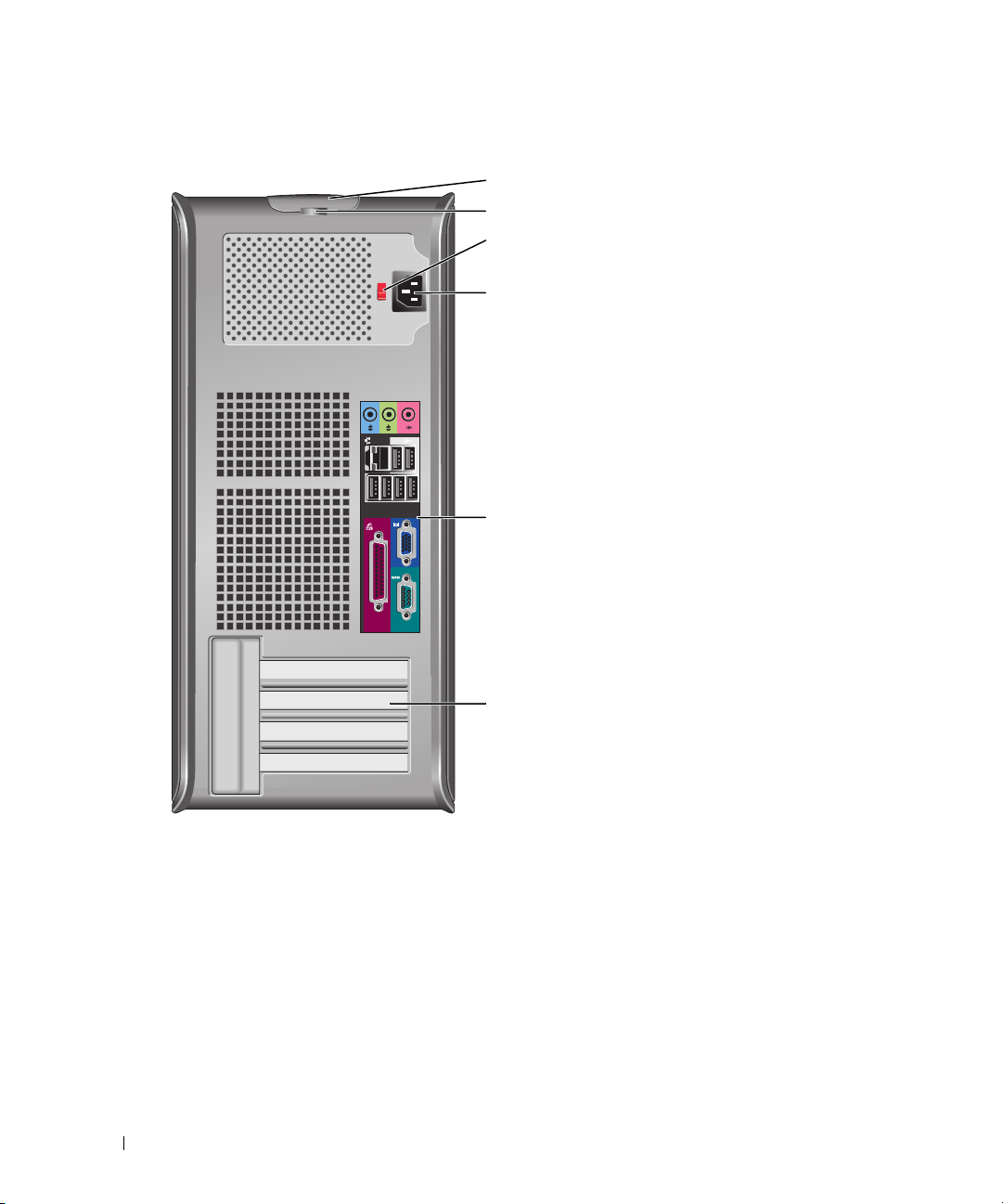
Mini Tower Computer — Front View
www.dell.com | support.dell.com
1
2
10
9
8
3
4
5
6
7
8 Quick Reference Guide
Page 9

1 CD/DVD drive
2 floppy drive
3 USB 2.0 connectors (2) Connect USB devices such as a mouse, keyboard, memory key, printer, joystick, and
4 LAN indicator light
5 diagnostic lights
6 power button Press this button to turn on the computer.
7 power light The power light illuminates and blinks or remains solid to indicate different operating
8 hard-drive activity light
9 headphone connector Use the headphone connector to attach headphones and most kinds of speakers.
10 microphone connector Use the microphone connector to attach a microphone.
Insert a CD or DVD (if applicable) into this drive.
Insert a floppy disk into this drive.
computer speakers into either of the USB connectors.
It is recommended that you use the USB connectors on the back panel for devices that
typically remain connected, such as printers and keyboards.
This light indicates that a LAN (network) connection is established.
Use these lights to help you troubleshoot a computer problem based on the diagnostic
code. For more information, see "Diagnostic Lights" on page 32.
NOTICE: To avoid losing data, do not turn off the computer by pressing the power
button for 6 seconds or longer. Instead, perform an operating system shutdown.
NOTICE: If your operating system has ACPI enabled, when you press the power
button the computer will perform an operating system shutdown.
states:
• No light — The computer is turned off.
• Steady green — The computer is in a normal operating state.
• Blinking green — The computer is in a power-saving mode.
• Blinking or solid amber — See "Power Problems" in your online
To exit from a power-saving mode, press the power button or use the keyboard or the
mouse if it is configured as a wake device in the Windows Device Manager. For more
information about sleep modes and exiting from a power-saving mode, see "Power
Management"
See "System Lights" on page 31 for a description of power light patterns that can help
you troubleshoot problems with your computer.
This light flickers when the hard drive is in use.
in your online
User’s Guide.
User’s Guide.
Quick Reference Guide 9
Page 10
Mini Tower Computer — Back View
www.dell.com | support.dell.com
1
2
3
4
5
10 Quick Reference Guide
6
Page 11
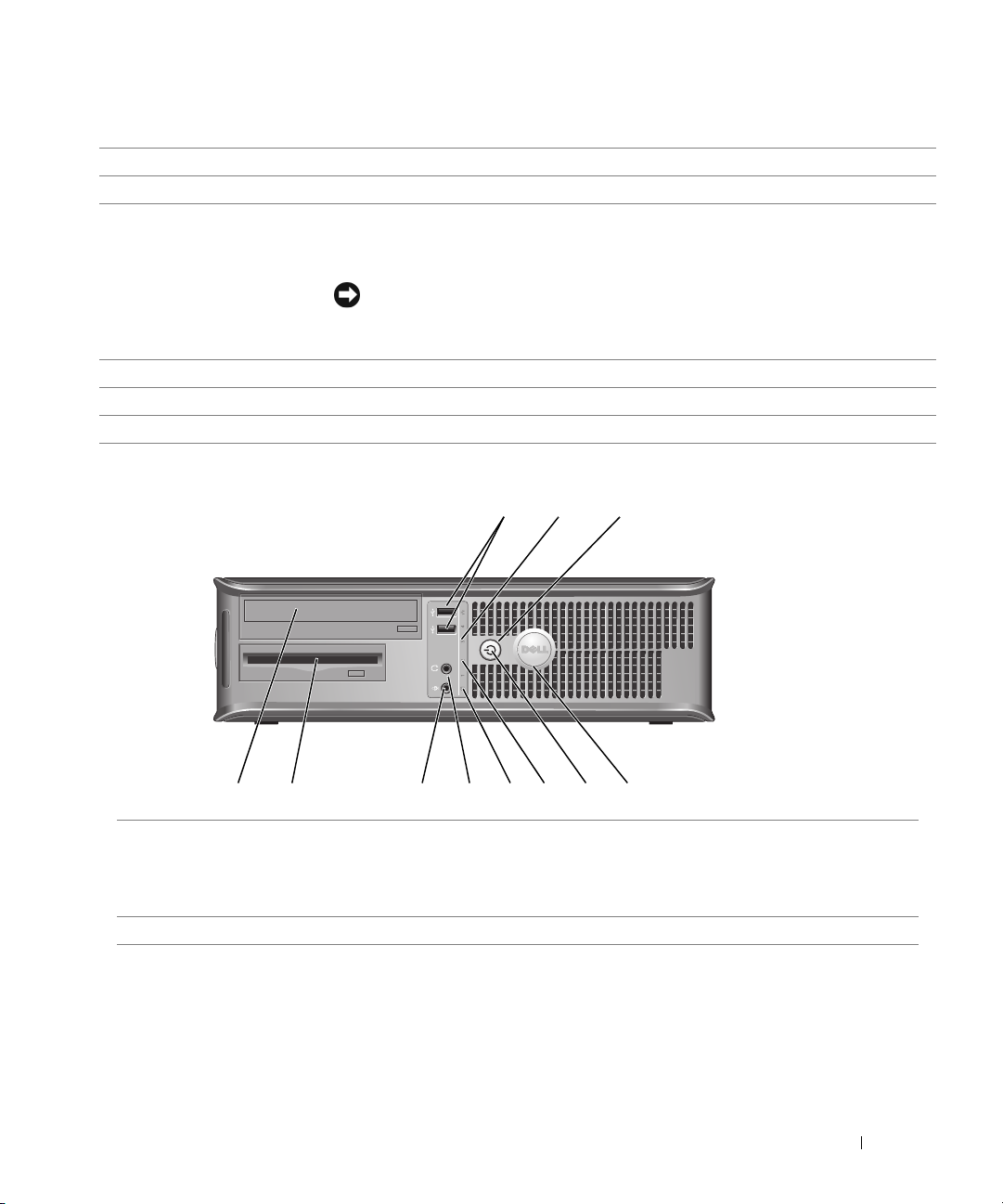
1
cover release latch This latch allows you to open the computer cover.
2
padlock ring Insert a padlock to lock the computer cover.
3 voltage selection switch Your computer is equipped with a manual voltage-selection switch.
To avoid damaging a computer with a manual voltage-selection switch, set the switch
to the voltage that most closely matches the AC power available in your location.
NOTICE: In Japan, the voltage selection switch must be set to 115-V.
Also, ensure that your monitor and attached devices are electrically rated to operate
with the AC power available in your location.
4 power connector Insert the power cable into this connector.
5 back-panel connectors Plug serial, USB, and other devices into the appropriate connector.
6 card slots You can access connectors for any installed PCI and PCI Express cards.
Desktop Computer — Front View
2
89
7
1 USB 2.0 connectors (2) Connect USB devices such as a mouse, keyboard, memory key, printer, joystick,
and computer speakers into either of the USB connectors.
It is recommended that you use the USB connectors on the back panel for devices
that typically remain connected, such as printers and keyboards.
2 LAN indicator light This light indicates that a LAN (network) connection is established.
3
514611 10
Quick Reference Guide 11
Page 12

3 power button Press this button to turn on the computer.
NOTICE: To avoid losing data, do not turn off the computer by pressing the
power button for 6 seconds or longer. Instead, perform an operating system
shutdown.
NOTICE: If your operating system has ACPI enabled, when you press the power
button the computer will perform an operating system shutdown.
4 Dell badge The badge can be rotated to match the orientation of your computer. To rotate
the badge, place your fingers around the outside of the badge, press firmly, and
turn the badge. You can also rotate the badge using the slot provided near the
bottom of the badge.
5 power light This light turns on and blinks or remains solid to indicate different operating
www.dell.com | support.dell.com
6 diagnostic lights Use these lights to help you troubleshoot a computer problem based on the
7 hard-drive activity light This light flickers when the hard drive is in use.
8 headphone connector Use the headphone connector to attach headphones and most kinds of speakers.
9 microphone connector Use the microphone connector to attach a microphone.
10 floppy drive Insert a floppy disk into this drive.
11 CD/DVD drive Insert a CD or DVD (if applicable) into this drive.
states:
• No light — The computer is turned off.
• Steady green — The computer is in a normal operating state.
• Blinking green — The computer is in a power-saving mode.
• Blinking or solid amber — See "Power Problems" in your online
To exit from a power-saving mode, press the power button or use the keyboard or
the mouse if it is configured as a wake device in the Windows Device Manager. For
more information about sleep modes and exiting from a power-saving mode, see
"Power Management"
See "System Lights" on page 31 for a description of power light patterns that can
help you troubleshoot problems with your computer.
diagnostic code. For more information, see "Diagnostic Lights" on page 32.
in your online
User’s Guide.
User’s Guide
.
12 Quick Reference Guide
Page 13
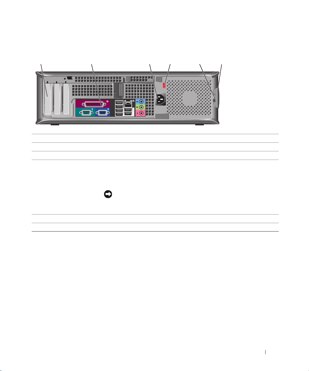
Desktop Computer — Back View
1
1 card slots You can access connectors for any installed PCI and PCI Express cards.
2 back-panel connectors Plug serial, USB, and other devices into the appropriate connector.
3 power connector Insert the power cable into this connector.
4 voltage selection switch Your computer is equipped with a manual voltage-selection switch.
5 padlock ring Insert a padlock to lock the computer cover.
6 cover release latch Use this latch to open the computer cover.
2 3 4 6
To avoid damaging a computer with a manual voltage-selection switch, set the
switch to the voltage that most closely matches the AC power available in your
location.
NOTICE: In Japan, the voltage selection switch must be set to 115-V.
Also, ensure that your monitor and attached devices are electrically rated to
operate with the AC power available in your location.
5
Quick Reference Guide 13
Page 14
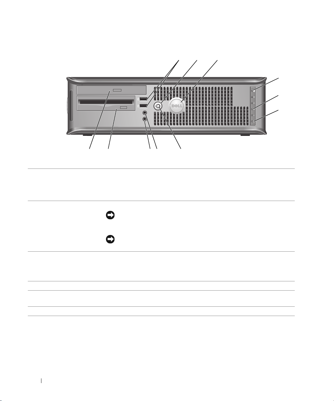
Small Form Factor Computer — Front View
2
1
www.dell.com | support.dell.com
11 10
1 USB 2.0 connectors (2) Connect USB devices such as a mouse, keyboard, memory key, printer, joystick,
and computer speakers into either of the USB connectors.
It is recommended that you use the USB connectors on the back panel for devices
that typically remain connected, such as printers and keyboards.
2 power button Press this button to turn on the computer.
NOTICE: To avoid losing data, do not turn off the computer by pressing the
power button for 6 seconds or longer. Instead, perform an operating system
shutdown.
89
7
3
4
5
6
NOTICE: If your operating system has ACPI enabled, when you press the power
button the computer will perform an operating system shutdown.
3 Dell badge The badge can be rotated to match the orientation of your computer. To rotate
the badge, place fingers around the outside of the badge, press firmly, and turn the
badge. You can also rotate the badge using the slot provided near the bottom of
the badge.
4 LAN indicator light This light indicates that a LAN (network) connection is established.
5 diagnostic lights Use these lights to help you troubleshoot a computer problem based on the
diagnostic code. For more information, see "Diagnostic Lights" on page 32.
6 hard-drive activity light This light flickers when the hard drive is in use.
14 Quick Reference Guide
Page 15
7 power light Turns on and blinks or remains solid to indicate different operating states:
• No light — The computer is turned off.
• Steady green — The computer is in a normal operating state.
• Blinking green — The computer is in a power-saving mode.
• Blinking or solid amber — See "Power Problems" in your online
To exit from a power-saving mode, press the power button or use the keyboard or
the mouse if it is configured as a wake device in the Windows Device Manager. For
more information about sleep modes and exiting from a power-saving mode, see
"Power Management" in your online User’s Guide.
See "System Lights" on page 31 for a description of power light patterns that can
help you troubleshoot problems with your computer.
8 headphone connector Use the headphone connector to attach headphones and most kinds of speakers.
9 microphone connector Use the microphone connector to attach a microphone.
10 floppy drive Insert a floppy disk into this drive.
11 CD/DVD drive Insert a CD or DVD (if applicable) into this drive.
User’s Guide
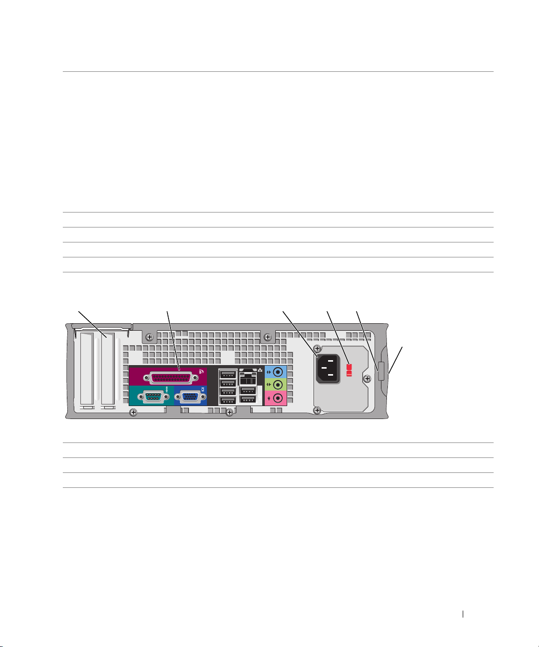
Small Form Factor Computer — Back View
51 2 3 4
6
.
1 card slots You can access connectors for any installed PCI and PCI Express cards.
2 back-panel connectors Plug serial, USB, and other devices into the appropriate connector.
3 power connector Connect the power cable to this connector.
Quick Reference Guide 15
Page 16
4 voltage selection switch Your computer is equipped with a manual voltage-selection switch.
To avoid damaging a computer with a manual voltage-selection switch, set the
switch to the voltage that most closely matches the AC power available in your
location.
NOTICE: In Japan, the voltage selection switch must be set to 115-V.
Also, ensure that your monitor and attached devices are electrically rated to
operate with the AC power available in your location.
5 padlock ring Insert a padlock to lock the computer cover.
6 cover release latch Use this latch to open the computer cover.
www.dell.com | support.dell.com
1
2
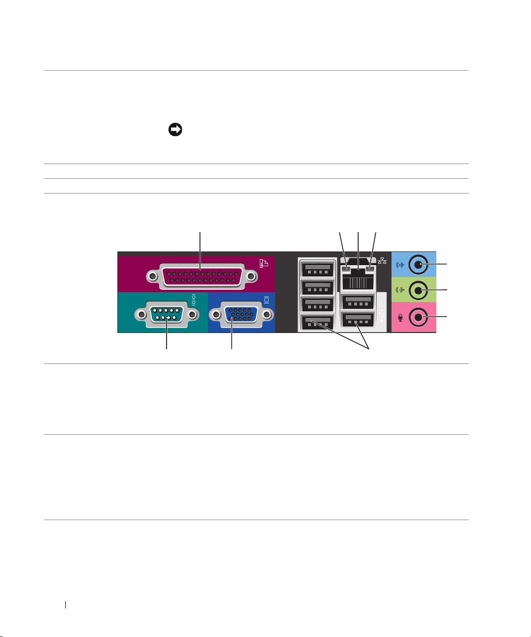
Back-Panel Connectors
parallel connector Connect a parallel device, such as a printer, to the parallel connector. If you have a
link integrity light • Green — A good connection exists between a 10-Mbps network and the
13
10 9 8
USB printer, plug it into a USB connector.
24
5
6
7
NOTE: The integrated parallel connector is automatically disabled if the computer
detects an installed card containing a parallel connector configured to the same
address. For more information, see "System Setup Options" in your online User’s
Guide.
computer.
• Orange — A good connection exists between a 100-Mbps network and the
computer.
• Yellow — A good connection exists between a 1-Gbps (or 1000-Mbps) network
and the computer.
• Off — The computer is not detecting a physical connection to the network.
16 Quick Reference Guide
Page 17

3
network adapter
connector
To attach your computer to a network or broadband device, connect one end of a
network cable to either a network jack or your network or broadband device. Connect
the other end of the network cable to the network adapter connector on the back
panel of your computer. A click indicates that the network cable has been securely
attached.
NOTE: Do not plug a telephone cable into the network connector.
On computers with a network adapter card, use the connector on the card.
It is recommended that you use Category 5 wiring and connectors for your network.
If you must use Category 3 wiring, force the network speed to 10 Mbps to ensure
reliable operation.
4
network activity light This light flashes yellow when the computer is transmitting or receiving network
data. A high volume of network traffic may make this light appear to be in a steady
"on" state.
5
line-in connector Use the blue line-in connector to attach a record/playback device such as a cassette
player, CD player, or VCR.
On computers with a sound card, use the connector on the card.
6
line-out connector Use the green line-out connector to attach headphones and most speakers with
integrated amplifiers.
On computers with a sound card, use the connector on the card.
7
microphone connector Use the pink microphone connector to attach a personal computer microphone for
voice or musical input into a sound or telephony program.
On computers with a sound card, the microphone connector is on the card.
8
USB 2.0 connectors (6)
video connector Plug the cable from your VGA-compatible monitor into the blue connector.
9
Connect USB devices such as a mouse, keyboard, memory key, printer, joystick,
and computer speakers into any of the USB connectors.
NOTE: If you purchased an optional graphics card, this connector will be covered by
a cap. Connect your monitor to the connector on the graphics card. Do not remove
the cap.
NOTE: If you are using a graphics card that supports dual monitors, use the y-cable
that came with your computer.
10
serial connector Connect a serial device, such as a handheld device, to the serial port. The default
designations are COM1 for serial connector 1 and COM2 for serial connector 2.
For more information, see "System Setup Options" in your online
User’s Guide
.
Quick Reference Guide 17
Page 18

Removing the Computer Cover
CAUTION: Before you begin any of the procedures in this section, follow the safety instructions in the
Product Information Guide.
CAUTION: To guard against electrical shock, always unplug your computer from the electrical outlet
before removing the cover.
Before You Begin
NOTICE: To avoid losing data, save and close any open files and exit any open programs before you turn
off your computer.
1
www.dell.com | support.dell.com
Shut down the operating system:
a
Save and close any open files, exit any open programs, click the
click
b
In the
The computer turns off after the operating system shutdown process is complete.
2
Ensure that the computer and any attached devices are turned off. If your computer and
attached devices did not automatically turn off when you shut down your operating system,
turn them off now.
Before Working Inside Your Computer
Use the following safety guidelines to help protect your computer from potential damage and to
help ensure your own personal safety.
Turn Off Computer
Turn off computer
.
window, click
Tur n o ff
Start
button, and then
.
CAUTION: Before you begin any of the procedures in this section, follow the safety instructions in the
Product Information Guide.
NOTICE: Only a certified service technician should perform repairs on your computer. Damage due to
servicing that is not authorized by Dell is not covered by your warranty.
NOTICE: When you disconnect a cable, pull on its connector or on its strain-relief loop, not on the cable
itself. Some cables have a connector with locking tabs; if you are disconnecting this type of cable, press
in on the locking tabs before you disconnect the cable. As you pull connectors apart, keep them evenly
aligned to avoid bending any connector pins. Also, before you connect a cable, ensure that both
connectors are correctly oriented and aligned.
To avoid damaging the computer, perform the following steps before you begin working inside
the computer.
1
Turn off your computer if it is not already turned off.
NOTICE: To disconnect a network cable, first unplug the cable from your computer and then unplug it
from the network wall jack.
2
Disconnect any telephone or telecommunication lines from the computer.
18 Quick Reference Guide
Page 19

3
Disconnect your computer and all attached devices from their electrical outlets, and then
press the power button to ground the system board.
4
Remove the computer stand, if it is attached.
CAUTION: To guard against electrical shock, always unplug your computer from the electrical outlet
before removing the cover.
NOTICE: Before touching anything inside your computer, ground yourself by touching an unpainted
metal surface, such as the metal at the back of the computer. While you work, periodically touch an
unpainted metal surface to dissipate any static electricity that could harm internal components.
Mini Tower Computer
NOTICE: Before touching anything inside your computer, ground yourself by touching an unpainted
metal surface. While you work, periodically touch an unpainted metal surface to dissipate any static
electricity that could harm internal components.
1
Follow the procedures in "Before You Begin" on page 18.
2
If you have installed a padlock through the padlock ring on the back panel, remove the
padlock.
3
Lay the computer on its side as shown in the following illustration.
Quick Reference Guide 19
Page 20
1
www.dell.com | support.dell.com
2
3
4
1
2
3
4
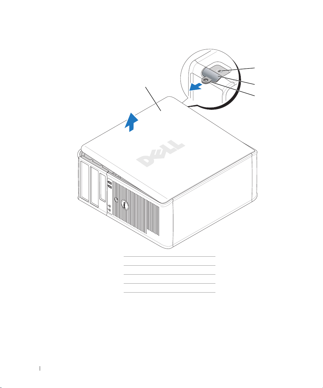
Slide the cover release latch back as you lift the cover.
5
Grip the sides of the computer cover and pivot the cover up using the hinge tabs as leverage
points.
6
Remove the cover from the hinge tabs and set it aside on a clean, nonabrasive surface.
20 Quick Reference Guide
1
security cable slot
2
cover release latch
3
padlock ring
4
computer cover
Page 21
Desktop Computer
NOTICE: Before touching anything inside your computer, ground yourself by touching an unpainted
metal surface. While you work, periodically touch an unpainted metal surface to dissipate any static
electricity that could harm internal components.
1
Follow the procedures in "Before You Begin" on page 18.
2
If you have installed a padlock through the padlock ring on the back panel, remove the padlock.
3
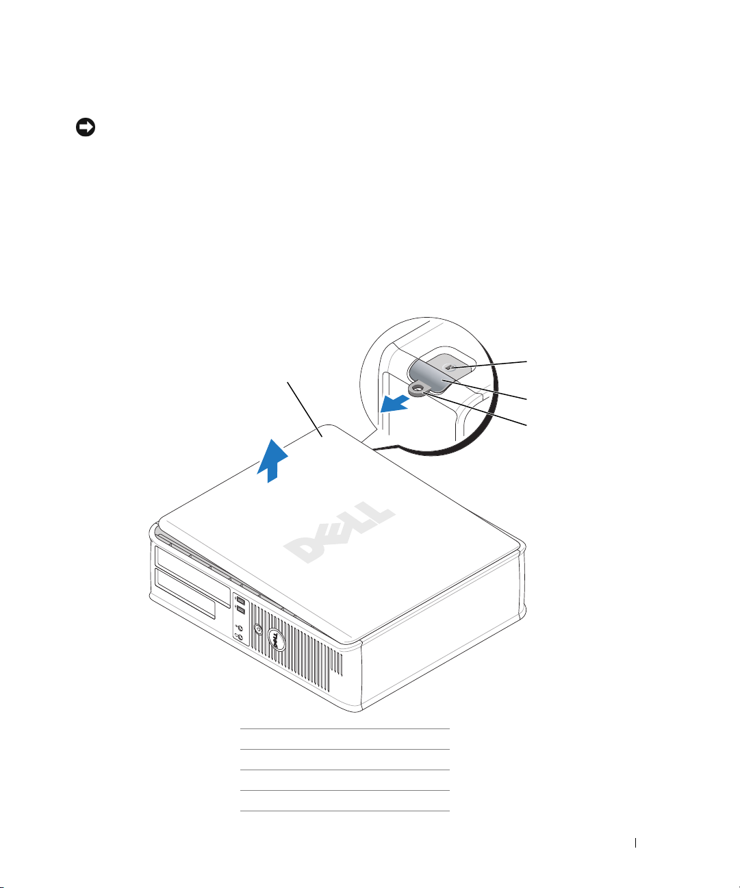
Slide the cover release latch back as you lift the cover.
4
Grip the sides of the computer cover and pivot the cover up using the hinge tabs as leverage
points.
5
Remove the cover from the hinge tabs and set it aside on a clean, nonabrasive surface.
1
4
2
3
1
security cable slot
2
cover release latch
3
padlock ring
4
computer cover
Quick Reference Guide 21
Page 22
Small Form Factor Computer
NOTICE: Before touching anything inside your computer, ground yourself by touching an unpainted
metal surface. While you work, periodically touch an unpainted metal surface to dissipate any static
electricity that could harm internal components.
1
Follow the procedures in "Before You Begin" on page 18.
2
If you have installed a padlock through the padlock ring on the back panel, remove the padlock.
3
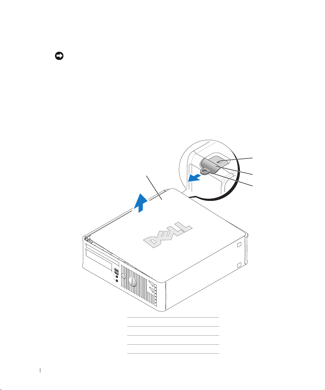
Slide the cover release latch back as you lift the cover.
4
Grip the sides of the computer cover and pivot the cover up using the hinge tabs as leverage
points.
5
www.dell.com | support.dell.com
Remove the cover from the hinge tabs and set it aside on a clean, nonabrasive surface.
1
4
1
security cable slot
2
cover release latch
3
padlock ring
4
computer cover
2
3
22 Quick Reference Guide
Page 23
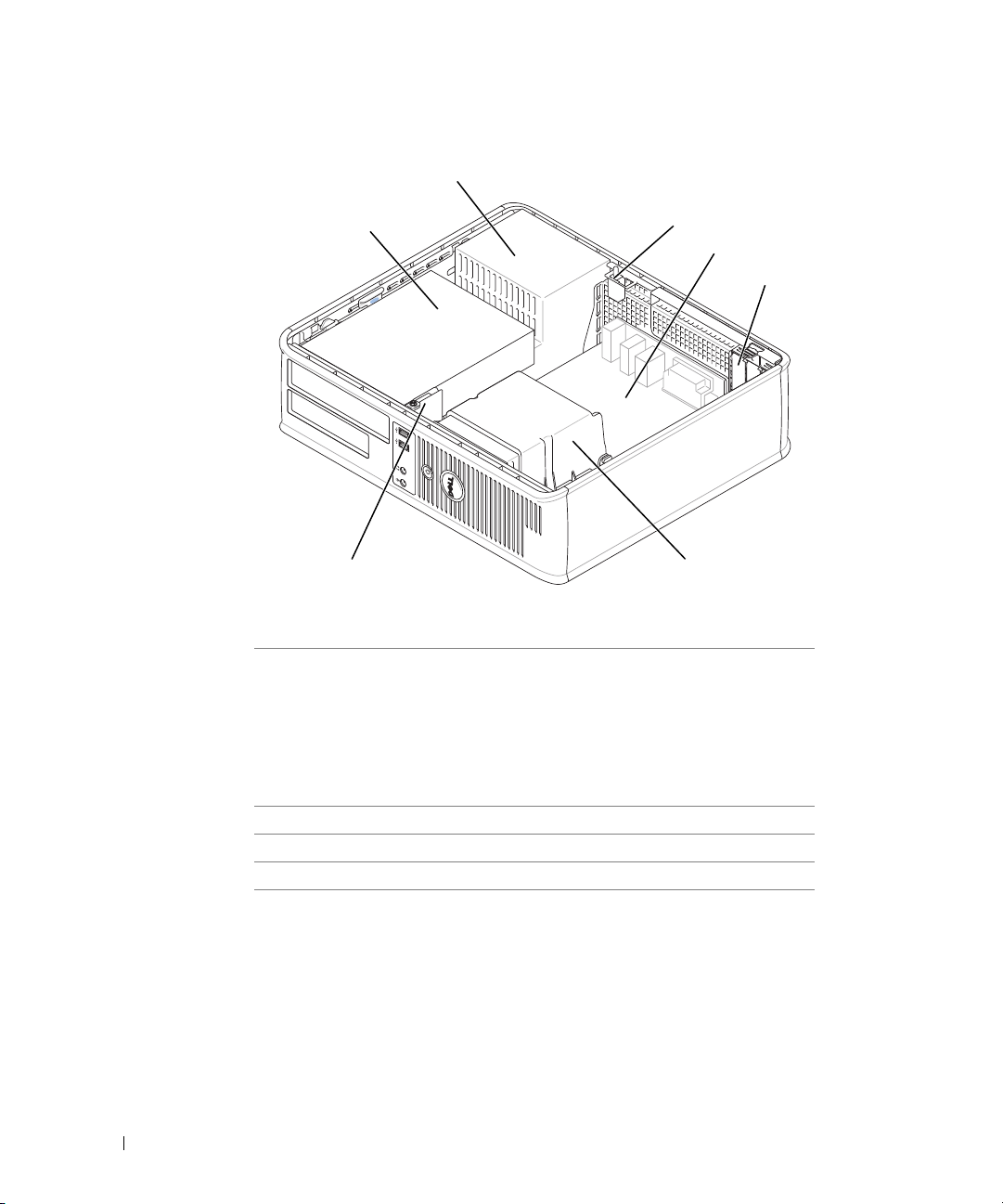
Inside Your Computer
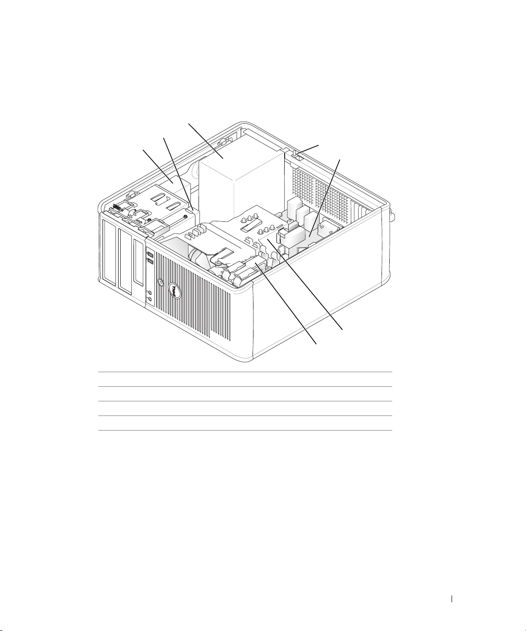
Mini Tower Computer
2
1
3
4
5
6
7
1 CD/DVD drive 5 system board
2 floppy drive 6 heat sink assembly
3 power supply 7 hard drive
4 chassis intrusion switch
Quick Reference Guide 23
Page 24
Desktop Computer
2
www.dell.com | support.dell.com
1
7
1 drives bay (CD/DVD,
floppy, or hard drive)
2 power supply 6 heat sink assembly
3 chassis intrusion switch 7 front I/O panel
4 system board
5 two low-profile PCI card slots
Optionally, you can install a PCI
riser card that converts one lowprofile PCI slot to two full-height
slots. A total of three card slots are
available: one low-profile and two
full-height card slots.
3
4
5
6
24 Quick Reference Guide
Page 25
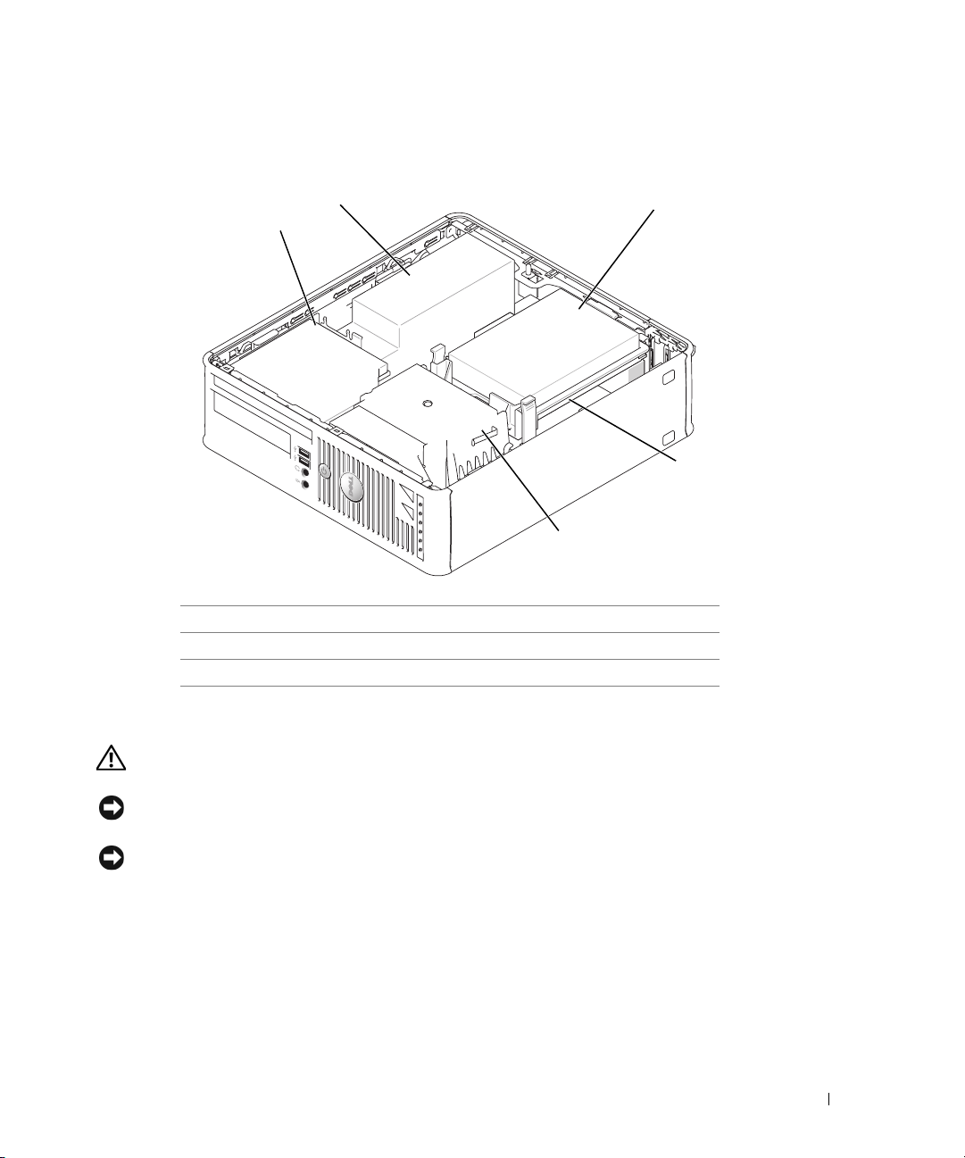
Small Form Factor Computer
2
1
5
1 CD/DVD drive 4 system board
2 power supply and fan 5 heat sink assembly
3 hard drive
3
4
Setting Up Your Computer
CAUTION: Before performing any of the procedures in this section, follow the safety instructions in
Product Information Guide.
NOTICE: If your computer has an expansion card installed (such as a modem card), connect the
appropriate cable to the card, not to the connector on the back panel.
NOTICE: To help allow the computer to maintain proper operating temperature, ensure that you do not
place the computer too close to a wall or other storage compartment that might prevent air circulation
around the chassis.
Quick Reference Guide 25
Page 26

You must complete all the steps to properly set up your computer. See the appropriate figures
that follow the instructions.
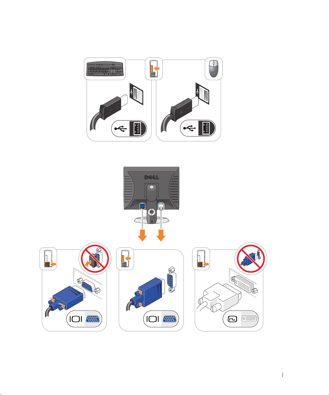
Connect the keyboard and mouse.
1
NOTICE: Do not attempt to operate a PS/2 mouse and a USB mouse simultaneously.
2
Connect the modem or network cable.
Insert the network cable, not the telephone line, into the network connector. If you have an
optional modem, connect the telephone line to the modem.
NOTICE: Do not connect a modem cable to the network adapter connector. Voltage from telephone
communications can cause damage to the network adapter.
3
www.dell.com | support.dell.com
Connect the monitor.
Align and gently insert the monitor cable to avoid bending connector pins. Tighten the
thumbscrews on the cable connectors.
NOTE: Some monitors have the video connector underneath the back of the screen. See the
documentation that came with your monitor for its connector locations.
4
Connect the speakers.
5
Connect power cables to the computer, monitor, and devices and connect the other ends of
the power cables to electrical outlets.
6
Verify that the voltage selection switch is set correctly for your location.
Your computer has a manual voltage-selection switch. Computers with a voltage selection
switch on the back panel must be manually set to operate at the correct operating voltage.
NOTICE: To avoid damaging a computer with a manual voltage-selection switch, set the switch to the
voltage that most closely matches the AC power available in your location.
NOTICE: In Japan, the voltage selection switch must be set to 115-V.
NOTE: Before you install any devices or software that did not ship with your computer, read the
documentation that came with the device or software, or contact the vendor to verify that the device or
software is compatible with your computer and operating system.
NOTE: Your computer may vary slightly from the following illustrations.
26 Quick Reference Guide
Page 27
Set Up Your Keyboard and Mouse
Set Up Your Monitor
Quick Reference Guide 27
Page 28
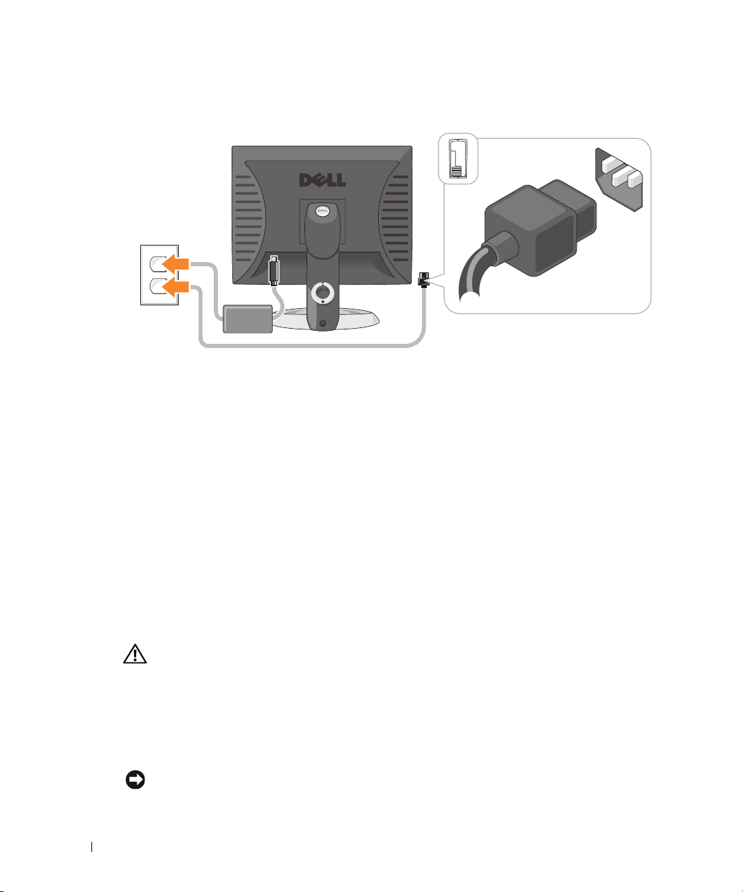
Power Connections
www.dell.com | support.dell.com
Solving Problems
Dell provides a number of tools to help you if your computer does not perform as expected. For
the latest troubleshooting information available for your computer, see the Dell Support website
at support.dell.com.
If computer problems occur that require help from Dell, write a detailed description of the error,
beep codes, or diagnostics light patterns; record your Express Service Code and Service Tag
below; and then contact Dell from the same location as your computer. For information on
contacting Dell, see your online User’s Guide.
See "Finding Information" on page 5 for an example of the Express Service Code and Service
Ta g .
Express Service Code: ___________________________
Service Tag: ___________________________
Dell Diagnostics
CAUTION: Before you begin any of the procedures in this section, follow the safety instructions in the
Product Information Guide.
When to Use the Dell Diagnostics
If you experience a problem with your computer, perform the checks in "Solving Problems" of
your online User’s Guide and run the Dell Diagnostics before you contact Dell for technical
assistance. For information on contacting Dell, see your online User’s Guide.
NOTICE: The Dell Diagnostics works only on Dell™ computers.
28 Quick Reference Guide
Page 29

Enter system setup (see "System Setup" in your online User’s Guide for instructions), review
your computer’s configuration information, and ensure that the device you want to test displays
in system setup and is active.
Start the Dell Diagnostics from either your hard drive or from the optional Drivers and
Utilities CD (also known as the ResourceCD).
Starting the Dell Diagnostics From Your Hard Drive
1
Turn on (or restart) your computer.
2
When the DELL™ logo appears, press <F12> immediately.
NOTE: If you see a message stating that no diagnostics utility partition has been found, run the Dell
Diagnostics from your Drivers and Utilities CD (optional) (see "Starting the Dell Diagnostics From the
Drivers and Utilities CD" on page 29).
If you wait too long and the operating system logo appears, continue to wait until you see the
Microsoft
3
When the boot device list appears, highlight
4
When the Dell Diagnostics
Starting the Dell Diagnostics From the Drivers and Utilities CD
1
Insert the
2
Shut down and restart the computer.
®
Windows® desktop. Then shut down your computer and try again.
Main Menu
Drivers and Utilities
Boot to Utility Partition
appears, select the test you want to run.
CD.
and press <Enter>.
When the DELL logo appears, press <F12> immediately.
If you wait too long and the Windows logo appears, continue to wait until you see the
Windows desktop. Then shut down your computer and try again.
NOTE: The next steps change the boot sequence for one time only. On the next start-up, the computer
boots according to the devices specified in system setup.
3
When the boot device list appears, highlight the listing for the CD/DVD drive and press
<Enter>.
4
Select the listing for the CD/DVD drive option from the CD boot menu.
5
Select the option to boot from the CD/DVD drive from the menu that appears.
6
Ty p e 1 to start the
7
Ty p e 2 to start the Dell Diagnostics.
8
Select
Run the 32 Bit Dell Diagnostics
Drivers and Utilities
CD menu.
from the numbered list. If multiple versions are listed,
select the version appropriate for your computer.
9
When the Dell Diagnostics
Main Menu
appears, select the test you want to run.
Quick Reference Guide 29
Page 30

Dell Diagnostics Main Menu
1
After the Dell Diagnostics loads and the
option you want.
Option Function
Express Test Performs a quick test of devices. This test typically takes 10 to 20 minutes and requires
Extended Test Performs a thorough check of devices. This test typically takes an hour or more and
Custom Test Tests a specific device. You can customize the tests you want to run.
www.dell.com | support.dell.com
Symptom Tree Lists the most common symptoms encountered and allows you to select a test based
2
If a problem is encountered during a test, a message appears with an error code and a
description of the problem. Write down the error code and problem description and follow
the instructions on the screen.
If you cannot resolve the error condition, contact Dell. For information on contacting Dell,
see your online
NOTE: The Service Tag for your computer is located at the top of each test screen. If you contact Dell,
technical support will ask for your Service Tag.
3
If you run a test from the
described in the following table for more information.
Main Menu
no interaction on your part. Run Express Test first to increase the possibility of tracing
the problem quickly.
requires you to answer questions periodically.
on the symptom of the problem you are having.
User’s Guide
.
Custom Test
or
Symptom Tree
screen appears, click the button for the
option, click the applicable tab
Tab Function
Results Displays the results of the test and any error conditions encountered.
Errors Displays error conditions encountered, error codes, and the problem description.
Help Describes the test and may indicate requirements for running the test.
Configuration Displays your hardware configuration for the selected device.
Parameters You can customize the test by changing the test settings.
4
When the tests are completed, if you are running the Dell Diagnostics from the
Utilities
5
Close the test screen to return to the
CD (optional), remove the CD.
restart the computer, close the
30 Quick Reference Guide
The Dell Diagnostics obtains configuration information for all devices from system
setup, memory, and various internal tests, and it displays the information in the device
list in the left pane of the screen. The device list may not display the names of all the
components installed on your computer or all devices attached to your computer.
Drivers and
Main Menu
Main Menu
screen. To exit the Dell Diagnostics and
screen.
Page 31

System Lights
Your power light may indicate a computer problem.
Power Light Problem Description Suggested Resolution
Solid green Power is on, and the computer is
operating normally.
Blinking green The computer is in a power-saving
mode.
Blinks green several
times and then
turns off
Solid yellow The Dell Diagnostics is running a
Blinking yellow A power supply or system board
Solid green and a
beep code during
POST
Solid green power
light, no beep code
and no video during
POST
Solid green power
light and no beep
code, but the
computer locks up
during POST
A configuration error exists. Check "Diagnostic Lights" on page 32 to see if
test, or a device on the system board
may be faulty or incorrectly installed.
failure has occurred.
A problem was detected while the
BIOS was executing.
The monitor or the graphics card
may be faulty or incorrectly installed.
An integrated system board device
may be faulty.
No corrective action is required.
Press the power button, move the mouse, or
press a key on the keyboard to wake the
computer.
the specific problem is identified.
If the Dell Diagnostics is running, allow the
testing to complete.
Check "Diagnostic Lights" on page 32 to see if
the specific problem is identified.
If the computer does not boot, contact Dell
for technical assistance.
contacting Dell, see your online
Check "Diagnostic Lights" on page 32 to see if
the specific problem is identified. See "Power
Problems" in your online User’s Guide.
See "Beep Codes" on page 35 for instructions
on diagnosing the beep code. Also, check
"Diagnostic Lights" on page 32 to see if the
specific problem is identified.
Check "Diagnostic Lights" on page 32 to see if
the specific problem is identified.
Check "Diagnostic Lights" on page 32 to see if
the specific problem is identified. If the
problem is not identified, contact Dell for
technical assistance.
contacting Dell, see your online
For information on
User’s Guide
For information on
User’s Guide
.
.
Quick Reference Guide 31
Page 32

Diagnostic Lights
CAUTION: Before you begin any of the procedures in this section, follow the safety instructions in the
Product Information Guide.
To help you troubleshoot a problem, your computer has four lights labeled "1," "2," "3," and "4"
on the front or back panel. The lights can be "off" or green. When the computer starts normally,
the patterns or codes on the lights change as the boot process completes. When the computer
starts normally, the patterns or codes on the lights change as the boot process completes. If the
POST portion of system boot completes successfully, all four lights display solid green for a short
time, and then turn off. If the computer malfunctions during the POST process, the pattern
displayed on the LEDs may help identify where in the process the computer halted. If the
www.dell.com | support.dell.com
computer malfunctions after a successful POST, the diagnostic lights do not indicate the cause
of the problem.
NOTE: The orientation of the diagnostic lights may vary depending on the system type. The diagnostic
lights can appear either vertical or horizontal.
Light Pattern Problem Description Suggested Resolution
The computer is in a normal "off"
condition, or a possible pre-BIOS failure
has occurred.
The diagnostic lights are not lit after the
computer successfully boots to the
operating system.
A possible BIOS failure has occurred; the
computer is in the recovery mode.
A possible processor failure has occurred. Reinstall the processor and restart the
Plug the computer into a working
electrical outlet and press the power
button.
Run the BIOS Recovery utility, wait for
recovery completion, and then restart the
computer.
computer.
the processor, see your online
For information on reinstalling
User’s Guide
.
32 Quick Reference Guide
Page 33

Light Pattern Problem Description Suggested Resolution
Memory modules are detected, but a
memory failure has occurred.
A possible graphics card failure has
occurred.
A possible floppy or hard drive failure has
occurred.
• If you have one memory module
installed, reinstall it and restart the
computer. For information on
reinstalling memory modules, see your
User’s Guide
online
• If you have two or more memory
modules installed, remove the modules,
reinstall one module, and then restart
the computer. If the computer starts
normally, reinstall an additional module.
Continue until you have identified a
faulty module or reinstalled all modules
without error.
• If available, install properly working
memory of the same type into your
computer.
• If the problem persists,
information on contacting Dell, see your
online
User’s Guide
• If the computer has a graphics card,
remove the card, reinstall it, and then
restart the computer.
• If the problem still exists, install a
graphics card that you know works and
restart the computer.
• If the problem persists or the computer
has integrated graphics,
For information on contacting Dell, see
your online
Reseat all power and data cables and
restart the computer.
User’s Guide
.
contact Dell
.
contact Dell
.
. For
.
A possible USB failure has occurred. Reinstall all USB devices, check cable
connections, and then restart the
computer.
Quick Reference Guide 33
Page 34

Light Pattern Problem Description Suggested Resolution
www.dell.com | support.dell.com
No memory modules are detected.
Memory modules are detected, but a
memory configuration or compatibility
error exists.
A failure has occurred.
This pattern also displays when you enter
system setup and may not indicate a
problem.
After POST is complete, all four
diagnostic lights turn green briefly before
turning off to indicate normal operating
condition.
• If you have one memory module
installed, reinstall it and restart the
computer. For information on
reinstalling memory modules, see your
User’s Guide
online
• If you have two or more memory
modules installed, remove the modules,
reinstall one module, and then restart
the computer. If the computer starts
normally, reinstall an additional module.
Continue until you have identified a
faulty module or reinstalled all modules
without error.
• If available, install properly working
memory of the same type into your
computer.
• If the problem persists,
information on contacting Dell, see your
online
User’s Guide
• Ensure that no
module/memory connector placement
requirements
• Verify that the
you are installing are compatible with
your computer.
• If the problem persists,
information on contacting Dell, see your
User’s Guide
online
• Ensure that the cables are properly
connected to the system board from the
hard drive, CD drive, and DVD drive.
• Check the computer message that
appears on your monitor screen.
• If the problem persists,
information on contacting Dell, see your
User’s Guide
online
None.
.
contact Dell
.
special memory
exist.
memory modules
contact Dell
.
contact Dell
.
that
. For
. For
. For
34 Quick Reference Guide
Page 35

Beep Codes
Your computer might emit a series of beeps during start-up if the monitor cannot display errors
or problems. This series of beeps, called a beep code, identifies a problem. One possible beep
code (code 1-3-1) consists of one beep, a burst of three beeps, and then one beep. This beep
code tells you that the computer encountered a memory problem.
If your computer beeps during start-up:
1
Write down the beep code.
2
See "Dell Diagnostics" on page 28 to identify a more serious cause.
3
Contact Dell for technical assistance. For information on contacting Dell, see your online
User’s Guide
Code Cause Code Cause
1-1-2 Microprocessor register failure 3-1-4 Slave interrupt mask register failure
1-1-3 NVRAM read/write failure 3-2-2 Interrupt vector loading failure
1-1-4 ROM BIOS checksum failure 3-2-4 Keyboard Controller test failure
1-2-1 Programmable interval timer failure 3-3-1 NVRAM power loss
1-2-2 DMA initialization failure 3-3-2 Invalid NVRAM configuration
1-2-3 DMA page register read/write
1-3 Video Memory test failure 3-4-1 Screen initialization failure
1-3-1 through 2-4-4 Memory not being properly
3-1-1 Slave DMA register failure 3-4-3 Search for video ROM failure
3-1-2 Master DMA register failure 4-2-1 No timer tick
3-1-3 Master interrupt mask register
4-2-3 Gate A20 failure 4-4-1 Serial or parallel port test failure
4-2-4 Unexpected interrupt in protected
4-3-1 Memory failure above address
4-3-3 Timer-chip counter 2 failure 4-4-4 Cache test failure
4-3-4 Time-of-day clock stopped
.
failure
identified or used
failure
mode
0FFFFh
3-3-4 Video Memory test failure
3-4-2 Screen retrace failure
4-2-2 Shutdown failure
4-4-2 Failure to decompress code to
shadowed memory
4-4-3 Math-coprocessor test failure
Quick Reference Guide 35
Page 36

Running the Dell™ IDE Hard Drive Diagnostics
The Dell IDE Hard Drive Diagnostics is a utility that tests the hard drive to troubleshoot or
confirm a hard drive failure.
1
Turn on your computer (if your computer is already on, restart it).
2
When
F2= Setup
<Ctrl><Alt><d>.
3
Follow the instructions on the screen.
If a failure is reported, see "Hard Drive Problems" in the "Solving Problems" section of the online
User’s Guide.
appears in the upper-right corner of the screen, press
www.dell.com | support.dell.com
Resolving Software and Hardware Incompatibilities
If a device is either not detected during the operating system setup or is detected but incorrectly
configured, you can use the Hardware Troubleshooter to resolve the incompatibility.
1
Click the
2
Ty p e
hardware troubleshooter
search.
3
Click
Hardware Troubleshooter
4
In the
Hardware Troubleshooter
computer
Using Microsoft® Windows® XP System Restore
The Microsoft Windows XP operating system provides System Restore to allow you to return
your computer to an earlier operating state (without affecting data files) if changes to the
hardware, software, or other system settings have left the computer in an undesirable operating
state. See the Windows Help and Support Center for information on using System Restore. To
access the Windows Help and Support Center, see "Windows Help and Support Center" on
page 7.
NOTICE: Make regular backups of your data files. System Restore does not monitor your data files or
recover them.
Creating a Restore Point
1
Click the
2
Click
System Restore
3
Follow the instructions on the screen.
Start
button and click
, and click
Start
button and click
Next
.
Help and Support
in the
list, click
.
Help and Support
.
in the
Search
field and click the arrow to start the
Search Results
list.
I need to resolve a hardware conflict on my
.
36 Quick Reference Guide
Page 37

Restoring the Computer to an Earlier Operating State
NOTICE: Before you restore the computer to an earlier operating state, save and close any open files
and exit any open programs. Do not alter, open, or delete any files or programs until the system
restoration is complete.
1
Click the
System Restore
2
Ensure that
3
Click a calendar date to which you want to restore your computer.
The
Start
button, point to
.
Restore my computer to an earlier time
Select a Restore Point
All Programs→
Accessories→
System Tools
is selected, and click
, and then click
Next
.
screen provides a calendar that allows you to see and select restore
points. All calendar dates with available restore points appear in boldface type.
4
Select a restore point and click
Next
.
If a calendar date has only one restore point, then that restore point is automatically selected.
If two or more restore points are available, click the restore point that you prefer.
5
Click
Next
.
The
Restoration Complete
screen appears after System Restore finishes collecting data and
then the computer restarts.
6
After the computer restarts, click OK.
To change the restore point, you can either repeat the steps using a different restore point, or
you can undo the restoration.
Undoing the Last System Restore
NOTICE: Before you undo the last system restore, save and close all open files and exit any open
programs. Do not alter, open, or delete any files or programs until the system restoration is complete.
1
Click the
System Restore
2
Click
3
Click
The
4
After the computer restarts, click OK.
Enabling System Restore
Start
button, point to
.
Undo my last restoration
Next
.
System Restore
screen appears and the computer restarts.
All Programs→ Accessories→ System Tools
and click
Next
.
, and then click
If you reinstall Windows XP with less than 200 MB of free hard-disk space available, System
Restore is automatically disabled. To verify that System Restore is enabled:
1
Click the
2
Click
Start
button and click
Control Pane l
Performance and Maintenance
.
.
Quick Reference Guide 37
Page 38

3
Click
System
4
Click the
5
Ensure that
Reinstalling Microsoft® Windows® XP
Before You Begin
NOTE: The procedures in this document were written for the Windows default view in Windows XP
Home Edition, so the steps will differ if you set your Dell™ computer to the Windows Classic view or are
using Windows XP Professional.
www.dell.com | support.dell.com
If you are considering reinstalling the Windows XP operating system to correct a problem with a
newly installed driver, first try using Windows XP Device Driver Rollback.
1
Click the
2
Under
Pick a Category
3
Click
System
4
In the
System Properties
5
Click
Device Manager
6
Right-click the device for which the new driver was installed and click
7
Click the
8
Click
Roll Back Driver
If Device Driver Rollback does not resolve the problem, then use System Restore (see "Using
Microsoft® Windows® XP System Restore" on page 36) to return your operating system to the
operating state it was in before you installed the new device driver.
.
System Restore
tab.
Turn off System Restore
Start
button and click
, click
Performance and Maintenance
.
window, click the
.
Drivers
tab.
.
is unchecked.
Control Pane
Hardware
l.
.
tab.
Properties
.
NOTE: The Drivers and Utilities CD contains drivers that were installed during assembly of the computer.
Use the Drivers and Utilities CD to load any required drivers, including the drivers required if your
computer has a RAID controller.
Reinstalling Windows XP
NOTICE: You must use Windows XP Service Pack 1 or later when you reinstall Windows XP.
NOTICE: Before performing the installation, back up all data files on your primary hard drive. For
conventional hard drive configurations, the primary hard drive is the first drive detected by the computer.
To reinstall Windows XP, you need the following items:
• Dell™
•Dell
Operating System
Drivers and Utilities
To reinstall Windows XP, perform all the steps in the following sections in the order in which
they are listed.
38 Quick Reference Guide
CD
CD
Page 39

The reinstallation process can take 1 to 2 hours to complete. After you reinstall the operating
system, you must also reinstall the device drivers, virus protection program, and other software.
NOTICE: The Operating System CD provides options for reinstalling Windows XP. The options can
overwrite files and possibly affect programs installed on your hard drive. Therefore, do not reinstall
Windows XP unless a Dell technical support representative instructs you to do so.
NOTICE: To prevent conflicts with Windows XP, disable any virus protection software installed on your
computer before you reinstall Windows XP. See the documentation that came with the software for
instructions.
Booting From the Operating System CD
1
Save and close any open files and exit any open programs.
2
Insert the
3
Restart the computer.
4
Press <F12> immediately after the DELL™ logo appears.
Operating System
CD. Click
Exit
if
Install Windows XP
message appears.
If the operating system logo appears, wait until you see the Windows desktop, and then shut
down the computer and try again.
5
Press the arrow keys to select
6
When the
Windows XP Setup
1
When the
Windows now
2
Read the information on the
Press any key to boot from CD
Windows XP Setup
.
CD-ROM
, and press <Enter>.
message appears, press any key.
screen appears, press <Enter> to select
Microsoft Windows Licensing Agreement
To set up
screen, and press
<F8> to accept the license agreement.
3
If your computer already has Windows XP installed and you want to recover your current
Windows XP data, type
4
If you want to install a new copy of Windows XP, press <Esc> to select that option.
5
Press <Enter> to select the highlighted partition (recommended), and follow the
r
to select the repair option, and remove the CD.
instructions on the screen.
The
Windows XP Setup
screen appears, and the operating system begins to copy files and
install the devices. The computer automatically restarts multiple times.
NOTICE: Do not press any key when the following message appears: Press any key to boot
from the CD
NOTE: The time required to complete the setup depends on the size of the hard drive and the speed of
your computer.
6
When the
location and click
.
Regional and Language Options
Next
.
screen appears, select the settings for your
Quick Reference Guide 39
Page 40

7
Enter your name and organization (optional) in the
Next
click
8
At the
Computer Name and Administrator Password
computer (or accept the one provided) and a password, and click
9
If the
Modem Dialing Information
Next
.
10
Enter the date, time, and time zone in the
11
If the
Networking Settings
12
If you are reinstalling Windows XP Professional and you are prompted to provide further
information regarding your network configuration, enter your selections. If you are unsure of
www.dell.com | support.dell.com
your settings, accept the default selections.
Windows XP installs the operating system components and configures the computer. The
computer automatically restarts.
NOTICE: Do not press any key when the following message appears: Press any key to boot
from the CD.
13
When the
14
When the
appears, click
15
When the
click
Next
16
When the
17
Click
Next
18
Click
Finish
19
Reinstall the appropriate drivers with the
20
Reinstall your virus protection software.
21
Reinstall your programs.
Personalize Your Software
.
window, enter a name for your
Next
.
screen appears, enter the requested information and click
screen appears, click
Welcome to Microsoft
Date and Time Settings
Typical
screen appears, click
and click
Next
window, and click
Next
.
.
How will this computer connect to the Internet?
Skip
.
Ready to register with Microsoft?
screen appears, select
No, not at this time
.
Who will use this computer?
screen appears, you can enter up to five users.
.
to complete the setup, and remove the CD.
Drivers and Utilities
CD.
screen, and
Next
message
and
.
NOTE: To reinstall and activate your Microsoft Office or Microsoft Works Suite programs, you need the
Product Key number located on the back of the Microsoft Office or Microsoft Works Suite CD sleeve.
40 Quick Reference Guide
Page 41

Using the Drivers and Utilities CD
To use the Drivers and Utilities CD (also known as the ResourceCD) while you are running the
Windows operating system:
NOTE: To access device drivers and user documentation, you must use the Drivers and Utilities CD while
you are running Windows.
1
Turn on the computer and allow it to boot to the Windows desktop.
2
Insert the
If you are using the
ResourceCD Installation
about to begin installation.
3
Click OK to continue.
To complete the installation, respond to the prompts offered by the installation program.
4
Click
5
Select the appropriate
Drivers for Your Computer
To display a list of device drivers for your computer:
Click
1
The
system, and then a list of device drivers for your system configuration is displayed on the
screen.
Drivers and Utilities
Drivers and Utilities
Next
at the
Welcome Dell System Owner
System Model, Operating System, Device Type,
My Drivers
Drivers and Utilities
in the
CD into the CD drive.
CD for the first time on this computer, the
window opens to inform you that the
screen.
To pi c
drop-down menu.
CD (optional) scans your computer’s hardware and operating
Drivers and Utilities
and
To pi c
.
CD is
2
Click the appropriate driver and follow the instructions to download the driver to your
computer.
To view all available drivers for your computer, click Drivers from the Topic drop-down menu.
Quick Reference Guide 41
Page 42

www.dell.com | support.dell.com
42 Quick Reference Guide
Page 43

Index
B
beep codes, 35
C
CDs
drivers and utilities, 7
operating system, 7
conflicts
software and hardware
incompatibilities, 36
cover
removing, 18
D
Dell
Premier Support website, 7
support site, 6
Dell Diagnostics, 28
Desktop System Software. See
DSS
diagnostics
beep codes, 35
Dell Diagnostics, 28
Drivers and Utilities CD, 5
documentation
device, 5
Drivers and Utilities CD, 5
online, 6-7
User’s Guide, 5
drivers
list of, 41
reinstalling, 5
Drivers and Utilities CD, 5
DSS, 5-6
E
error messages
beep codes, 35
diagnostic lights, 32
system lights, 31
H
hardware
beep codes, 35
conflicts, 36
Dell Diagnostics, 28
Hardware Troubleshooter, 36
Help and Support Center, 7
I
installing parts
before you begin, 18
IRQ conflicts, 36
L
labels
Microsoft Windows, 6
Service Tag, 6
lights
diagnostic, 32
system, 31
M
Microsoft Windows label, 6
O
operating system
CD, 7
Installation Guide, 7
reinstalling Windows XP, 38
P
power light
diagnosing problems with, 31
patterns, 9, 12, 15
problems. See troubleshooting
Index 43
Page 44

R
V
reinstalling
drivers, 5
Windows XP, 38
ResourceCD. See Drivers and
Utilities CD
S
Service Tag, 6
software
conflicts, 36
System Restore, 36
T
troubleshooting
beep codes, 35
conflicts, 36
Dell Diagnostics, 28
diagnostic lights, 32
Hardware Troubleshooter, 36
Help and Support Center, 7
restore computer to previous
operating state, 36
system lights, 31
voltage selection switch, 11,
13, 16
W
Windows XP
Hardware Troubleshooter, 36
Help and Support Center, 7
reinstalling, 38
setup, 39
System Restore, 36
44 Index
Page 45

Dell™ OptiPlex™ GX520
Guide de référence rapide
Modèles DCTR, DCNE, DCSM
www.dell.com | support.dell.com
Page 46

Remarques, avis et précautions
REMARQUE : Une REMARQUE fournit des informations importantes qui vous aident à mieux utiliser votre ordinateur.
AVIS : Un AVIS vous avertit d’un risque de dommage matériel ou de perte de données et vous indique comment éviter le
problème.
PRÉCAUTION : Une PRÉCAUTION indique un danger d'endommagement du matériel, de blessure personnelle, ou de
mort.
Si vous avez acheté un ordinateur Dell™ série n, les références du présent document concernant les systèmes
d'exploitation Microsoft
Guide de référence rapide
Le
®
Windows® ne sont pas applicables.
, le CD
Drivers and Utilities
et le support du système d'exploitation sont en option et
peuvent ne pas être livrés avec votre ordinateur.
Abréviations et sigles
Pour une liste complète des abréviations et des sigles, reportez-vous au Glossaire du
____________________
Les informations de ce document sont sujettes à modification sans préavis.
© 2005–2006 Dell Inc. Tous droits réservés.
La reproduction de ce document, de quelque manière que ce soit, sans l'autorisation écrite de Dell Inc. est strictement interdite.
Marques utilisées dans ce document : Dell, OptiPlex et le logo DELL sont des marques de Dell Inc. ; Microsoft et Windows sont des marques
déposées de Microsoft Corporation ; Intel et Pentium sont des marques déposées de Intel Corporation.
D'autres marques et noms commerciaux peuvent être utilisés dans ce document pour faire référence aux entités se réclamant de ces marques
et de ces noms ou à leurs produits. Dell Inc. rejette tout intérêt propriétaire dans les marques et les noms commerciaux autres que les siens.
Guide d'utilisation
.
Modèles DCTR, DCNE, DCSM
Août 2006 Réf. R9730 Rév. A02
Page 47

Table des matières
Recherche d'informations . . . . . . . . . . . . . . . . . . . . . . . . . . . . 49
Vues du système
. . . . . . . . . . . . . . . . . . . . . . . . . . . . . . . . . 52
Ordinateur mini-tour — Vue frontale
Ordinateur mini-tour — Vue arrière
Ordinateur de bureau — Vue frontale
Ordinateur de bureau — Vue arrière
Ordinateur compact — Vue frontale
Ordinateur compact — Vue arrière
Connecteurs du panneau arrière
Retrait du capot de l'ordinateur
Avant de commencer
Ordinateur mini-tour
Ordinateur de bureau
Ordinateur compact
L’intérieur de votre ordinateur
Ordinateur mini-tour
Ordinateur de bureau
Ordinateur compact
. . . . . . . . . . . . . . . . . . . . . . . . . . . . 62
. . . . . . . . . . . . . . . . . . . . . . . . . . . . 63
. . . . . . . . . . . . . . . . . . . . . . . . . . . . 65
. . . . . . . . . . . . . . . . . . . . . . . . . . . . . 66
. . . . . . . . . . . . . . . . . . . . . . . . . . 67
. . . . . . . . . . . . . . . . . . . . . . . . . . . . 67
. . . . . . . . . . . . . . . . . . . . . . . . . . . . 68
. . . . . . . . . . . . . . . . . . . . . . . . . . . . . 69
Configuration de votre ordinateur
Résolution des problèmes
Dell Diagnostics
Voyants du système
. . . . . . . . . . . . . . . . . . . . . . . . . . . . 72
. . . . . . . . . . . . . . . . . . . . . . . . . . . . . . . 72
. . . . . . . . . . . . . . . . . . . . . . . . . . . . . 75
. . . . . . . . . . . . . . . . . . . . 52
. . . . . . . . . . . . . . . . . . . . 54
. . . . . . . . . . . . . . . . . . . 55
. . . . . . . . . . . . . . . . . . . . 57
. . . . . . . . . . . . . . . . . . . . 58
. . . . . . . . . . . . . . . . . . . . 59
. . . . . . . . . . . . . . . . . . . . . . 60
. . . . . . . . . . . . . . . . . . . . . . . . . 62
. . . . . . . . . . . . . . . . . . . . . . . . 69
Voyants de diagnostic
Codes sonores
. . . . . . . . . . . . . . . . . . . . . . . . . . . . . . 76
. . . . . . . . . . . . . . . . . . . . . . . . . . . . . . . 79
Exécution de Dell™ IDE Hard Drive Diagnostics
(diagnostics de disque dur IDE)
Résolution des incompatibilités logicielles et matérielles
Utilisation de la fonction Restauration du système
Microsoft
®
Windows® XP . . . . . . . . . . . . . . . . . . . . . . . . . 80
Réinstallation de Microsoft
Utilisation du CD Drivers and Utilities
. . . . . . . . . . . . . . . . . . . . . . 80
. . . . . . . . . 80
®
Windows® XP . . . . . . . . . . . . . . . . 82
. . . . . . . . . . . . . . . . . . . . . . 85
Index . . . . . . . . . . . . . . . . . . . . . . . . . . . . . . . . . . . . . . . . . 87
Table des matières 47
Page 48

48 Table des matières
Page 49

Recherche d'informations
REMARQUE : Certaines fonctions ne sont pas nécessairement disponibles sur votre ordinateur ou dans
tous les pays.
REMARQUE : Il est possible que des informations supplémentaires soient fournies avec votre ordinateur.
Que recherchez-vous ? Cherchez ici
• Programme de diagnostic pour mon
ordinateur
• Pilotes pour mon ordinateur
• Documentation concernant mon
ordinateur
• Documentation concernant mon
périphérique
• Logiciel DSS (Desktop System Software)
• Mises à jour et correctifs du système
d'exploitation
• Informations sur les garanties
• Termes et Conditions (États-Unis
uniquement)
• Consignes de sécurité
• Informations sur les réglementations
• Informations relatives à l'ergonomie
• Contrat de licence pour utilisateur final
• Comment retirer et remplacer des pièces
• Caractéristiques
• Comment configurer les paramètres du
système
• Comment déterminer et résoudre des
problèmes
CD Drivers and Utilities (Pilotes et utilitaires, également appelé CD
ResourceCD)
REMARQUE : Le CD Drivers and Utilities est en option et n'est pas
obligatoirement expédié avec votre ordinateur.
La documentation et les pilotes sont déjà
installés sur l'ordinateur. Vous pouvez utiliser ce
CD pour réinstaller les pilotes (reportez-vous à la
section « Utilisation du CD Drivers and
Utilities » à la page 85), exécuter Dell
Diagnostics (reportez-vous à la section
« Lancement de Dell Diagnostics à partir du CD
Drivers and Utilities » à la page 73) ou accéder à
la documentation.
Des fichiers « Lisez-moi » peuvent être inclus sur
votre CD afin de fournir des informations de
dernière minute concernant des modifications techniques apportées à votre
système ou des informations de référence destinées aux techniciens ou aux
utilisateurs expérimentés.
REMARQUE : Les dernières mises à jour des pilotes et de la documentation se
trouvent à l'adresse support.dell.com.
Desktop System Software (DSS )
Se trouve sur le CD Drivers and Utilities et le site Web de support de Dell à
l'adresse support.dell.com.
Guide d'information sur le produit Dell™
Guide d'utilisation
Disponible dans le Centre d'aide et de support de Microsoft
1
Cliquez sur le bouton
2
Cliquez sur
Le Guide d'utilisation est aussi disponible sur le CD Drivers and Utilities en
option.
Guides d'utilisation du système
Démarrer
, puis sur
Aide et Support
, puis sur
®
Windows® XP :
.
Guides d'utilisation
.
Guide de référence rapide 49
Page 50

Que recherchez-vous ? Cherchez ici
• Numéro de service et code de service
express
• Étiquette de licence Microsoft Windows
Numéro de service et licence Microsoft Windows
Ces étiquettes sont apposées sur votre ordinateur.
• Utilisez le numéro de service pour identifier
l'ordinateur lorsque vous visitez le site
support.dell.com
technique.
• Entrez le code de service express pour orienter votre appel lorsque vous
contactez le service de support technique.
• Solutions — Conseils et astuces de
dépannage, articles de techniciens, cours
en ligne, questions fréquemment posées
• Forum clients — Discussion en ligne
www.dell.com | support.dell.com
avec d'autres clients Dell
• Mises à niveau — Informations sur les
mises à niveau des composants, comme
la mémoire, l'unité de disque dur et le
système d'exploitation
• Service clientèle — Coordonnées, appels
de service et état des commandes,
garantie et informations sur les
réparations
• Service et support — État des appels de
service et historique du support, contrat
Site Web de support de Dell — support.dell.com
REMARQUE : Sélectionnez votre région pour afficher le site de support
approprié.
Le site Web de support technique de Dell fournit plusieurs outils en ligne,
notamment :
• Dépannage — Conseils et astuces, articles de techniciens et cours en ligne
• Mises à niveau — Informations sur les mises à niveau des composants,
comme la mémoire, l'unité de disque dur et le système d'exploitation
• Services et garanties — Coordonnées, état des commandes, garantie et
informations sur les réparations
• Téléchargements — Pilotes, correctifs et mises à jour logicielles
• Guides d'utilisation — Documentation de l'ordinateur et caractéristiques de
produit
de service, discussions en ligne avec le
support technique
• Référence — Documentation de
l'ordinateur, détails sur la configuration
de l'ordinateur, caractéristiques de
produit et livres blancs
• Téléchargements — Pilotes, correctifs et
mises à jour logicielles agréés
• Logiciel DSS (Desktop System
Software) — Si vous réinstallez le
système d'exploitation de l'ordinateur,
vous devez également réinstaller
l'utilitaire DSS. DSS fournit des mises à
jour essentielles pour le système
d'exploitation et la prise en charge des
lecteurs de disquette USB Dell™ de 3,5
pouces, des processeurs Intel
Pentium
®
M, des lecteurs optiques et des
®
périphériques USB. DSS est requis pour
le bon fonctionnement de votre
ordinateur Dell. Ce logiciel détecte
automatiquement votre ordinateur et son
système d'exploitation, et installe les
mises à jour appropriées à votre
configuration.
ou contactez le support
50 Guide de référence rapide
Page 51

Que recherchez-vous ? Cherchez ici
• État des appels de service et historique
du support
• Principaux problèmes techniques de mon
ordinateur
• Questions fréquemment posées
Site Web Dell Premier Support (Support Premier de Dell) —
premiersupport.dell.com
Le site Web Dell Premier Support est conçu pour les grandes entreprises, le
gouvernement et les établissements d'enseignement. Ce site n'est pas
nécessairement disponible dans toutes les régions.
• Téléchargements de fichiers
• Informations sur la configuration de
l'ordinateur
• Contrat de service de l'ordinateur
• Comment utiliser Windows XP
• Documentation sur mon ordinateur
• Documentation pour les périphériques
(pour un modem, par exemple)
• Comment réinstaller mon système
d'exploitation
Centre d'aide et de support de Windows
1
Cliquez sur le bouton
2
Entrez un mot ou une expression qui décrit votre problème, puis cliquez sur
l'icône en forme de flèche.
3
Cliquez sur la rubrique qui décrit votre problème.
4
Suivez les instructions qui s'affichent.
CD Operating System
REMARQUE : Le CD Operating System est en option et n'est pas
obligatoirement expédié avec tous les ordinateurs.
Le système d'exploitation est déjà installé sur votre ordinateur. Pour
réinstaller le système d'exploitation, utilisez le CD Operating System.
Reportez-vous au Guide d'utilisation en ligne pour plus d'informations.
• Informations réglementaires sur le
modèle et type de châssis
• DCTR — Châssis mini-tour
• DCNE — Châssis de bureau
• DCSM — Châssis compact
Démarrer
, puis sur
Aide et support
.
Après avoir réinstallé le système d'exploitation,
utilisez le CD Drivers and Utilities pour réinstaller
les pilotes des périphériques accompagnant votre
ordinateur.
L'étiquette de la Product key (clé de produit) de
votre système d'exploitation se trouve sur
l'ordinateur.
REMARQUE : La couleur du CD varie selon le système
d'exploitation que vous avez commandé.
Guide de référence rapide 51
Page 52

Vues du système
Ordinateur mini-tour — Vue frontale
www.dell.com | support.dell.com
1
2
10
9
8
3
4
5
6
7
52 Guide de référence rapide
Page 53

1 lecteur de CD/DVD
2 lecteur de disquette
3 connecteurs USB 2.0 (2) Reliez les périphériques USB tels qu'une souris, un clavier, une clé de mémoire, une
4 voyant LAN
5 voyants de diagnostic
6 bouton d'alimentation Appuyez sur ce bouton pour allumer l'ordinateur.
7 voyant d'alimentation Le voyant d'alimentation s'allume et clignote ou reste fixe, selon l'état de
8 voyant d'activité de
l'unité de disque dur
9 connecteur de casque Permet de connecter le casque et les haut-parleurs.
10 connecteur microphone Utilisez le connecteur de microphone pour brancher un microphone.
Insérez un CD ou un DVD (le cas échéant) dans ce lecteur.
Insérez une disquette dans ce lecteur.
imprimante, une manette de jeu et des haut-parleurs à l'un des connecteurs USB.
Il est recommandé d'utiliser les connecteurs USB situés à l'arrière de l'ordinateur pour
les périphériques connectés en permanence, comme l'imprimante et le clavier.
Ce voyant indique qu'une connexion LAN (réseau) est établie.
Utilisez ces voyants pour vous aider à résoudre les problèmes grâce au code de diagnostic.
Pour obtenir de plus amples informations, reportez-vous à la section « Voyants de
diagnostic » à la page 76.
AVIS : Afin d'éviter de perdre des données, n'éteignez pas l'ordinateur en appuyant
sur le bouton d'alimentation pendant 6 secondes ou plus. Procédez plutôt à un arrêt
du système d'exploitation.
AVIS : Si la fonctionnalité ACPI est activée sur votre système d'exploitation, lorsque
vous appuyez sur le bouton d'alimentation, l'ordinateur procède à un arrêt du
système d'exploitation.
fonctionnement :
• Éteint — L'ordinateur est éteint.
• Vert fixe — L'ordinateur fonctionne normalement.
• Vert clignotant — L'ordinateur est en mode d'économie d'énergie.
• Orange clignotant ou fixe — Reportez-vous à la section « Problèmes d'alimentation »
du
Guide d'utilisation
Pour quitter le mode d'économie d'énergie, appuyez sur le bouton d'alimentation ou
utilisez le clavier ou la souris si ce périphérique est configuré comme un périphérique
de réveil dans le Gestionnaire de périphériques Windows. Pour plus d'informations sur
les modes de mise en veille et sur la façon de quitter le mode d'économie d'énergie,
reportez-vous à la section « Gestion de l'alimentation »
Reportez-vous à la section « Voyants du système » à la page 75 pour obtenir une
description de la séquence du voyant d'alimentation pouvant vous aider à résoudre les
problèmes rencontrés avec votre ordinateur.
Ce voyant clignote rapidement lors de l'utilisation du disque dur.
en ligne.
du
Guide d'utilisation
en ligne.
Guide de référence rapide 53
Page 54

Ordinateur mini-tour — Vue arrière
www.dell.com | support.dell.com
1
2
3
4
5
54 Guide de référence rapide
6
Page 55

1
loquet de fermeture du
capot
2
anneau pour cadenas Insérez un cadenas pour verrouiller le capot de l'ordinateur.
3 sélecteur de tension Votre ordinateur est équipé d'un sélecteur de tension manuel.
4 connecteur
d'alimentation
5 connecteurs du panneau
arrière
6 logements de carte Permet d'accéder aux connecteurs de toutes les cartes PCI et PCI Express installées.
Ce loquet permet d'ouvrir le capot de l'ordinateur.
Pour éviter d'endommager un ordinateur équipé d'un sélecteur de tension manuel,
placez le sélecteur sur la valeur de tension la plus proche du courant électrique de la
prise secteur.
AVIS : Au Japon, le sélecteur de tension doit être réglé sur 115 V.
Assurez-vous également que votre moniteur et tous ses périphériques sont
électriquement réglés pour fonctionner avec la puissance en CA disponible dans votre
zone géographique.
Permet de brancher le câble d'alimentation.
Permettent de connecter les périphériques série, USB et les autres périphériques à leurs
connecteurs respectifs.
Ordinateur de bureau — Vue frontale
2
89
7
1 connecteurs USB 2.0 (2) Reliez les périphériques USB tels qu'une souris, un clavier, une clé de mémoire,
une imprimante, une manette de jeu et des haut-parleurs à l'un des connecteurs
USB.
Il est recommandé d'utiliser les connecteurs USB situés à l'arrière de l'ordinateur
pour les périphériques connectés en permanence, comme l'imprimante et le
clavier.
2 voyant LAN Ce voyant indique qu'une connexion (réseau) LAN est établie.
3
514611 10
Guide de référence rapide 55
Page 56

3 bouton d'alimentation Appuyez sur ce bouton pour allumer l'ordinateur.
AVIS : Afin d'éviter de perdre des données, n'éteignez pas l'ordinateur en
appuyant sur le bouton d'alimentation pendant 6 secondes ou plus. Procédez
plutôt à un arrêt du système d'exploitation.
AVIS : Si la fonctionnalité ACPI est activée sur votre système d'exploitation,
lorsque vous appuyez sur le bouton d'alimentation, l'ordinateur procède à un
arrêt du système d'exploitation.
4 badge Dell Le badge peut être pivoté pour correspondre à l'orientation de l'ordinateur. Pour le
faire pivoter, placez vos doigts sur le pourtour du badge, appuyez fermement
dessus, puis tournez-le. Vous pouvez également le faire pivoter à l'aide de
l'encoche située vers le bas du badge.
www.dell.com | support.dell.com
5 voyant d'alimentation Ce voyant s'allume et clignote ou reste fixe pour indiquer les états de
fonctionnement suivants :
• Éteint — L'ordinateur est éteint.
• Vert fixe — L'ordinateur fonctionne normalement.
• Vert clignotant — L'ordinateur est en mode d'économie d'énergie.
• Orange clignotant ou fixe — Reportez-vous à la section « Problèmes
d'alimentation » du
Pour quitter le mode d'économie d'énergie, appuyez sur le bouton d'alimentation
ou utilisez le clavier ou la souris si ce périphérique est configuré comme un
périphérique de réveil dans le Gestionnaire de périphériques Windows. Pour plus
d'informations sur les modes de mise en veille et sur la façon de quitter le mode
d'économie d'énergie, reportez-vous à la section « Gestion de l'alimentation »
Guide d'utilisation
Reportez-vous à la section « Voyants du système » à la page 75 pour obtenir une
description de la séquence du voyant d'alimentation pouvant vous aider à résoudre
les problèmes rencontrés avec votre ordinateur.
6 voyants de diagnostic Utilisez ces voyants pour vous aider à résoudre les problèmes grâce au code de
diagnostic. Pour obtenir de plus amples informations, reportez-vous à la section
« Voyants de diagnostic » à la page 76.
7 voyant d'activité de
l'unité de disque dur
8 connecteur de casque Permet de connecter le casque et les haut-parleurs.
9 connecteur microphone Utilisez le connecteur de microphone pour brancher un microphone.
10 lecteur de disquette Permet d'insérer une disquette.
11 lecteur de CD/DVD Permet d'insérer un CD ou un DVD (le cas échéant).
Ce voyant clignote lorsque le disque dur fonctionne.
Guide d'utilisation
en ligne.
en ligne.
du
56 Guide de référence rapide
Page 57

Ordinateur de bureau — Vue arrière
1
1 logements de carte Permet d'accéder aux connecteurs de toutes les cartes PCI et PCI Express
2 connecteurs du panneau
arrière
3 connecteur
d'alimentation
4 sélecteur de tension Votre ordinateur est équipé d'un sélecteur de tension manuel.
5 anneau pour cadenas Insérez un cadenas pour verrouiller le capot de l'ordinateur.
6 loquet de fermeture du
capot
2 3 4 6
installées.
Permettent de connecter les périphériques série, USB et les autres périphériques à
leurs connecteurs respectifs.
Permet de brancher le câble d'alimentation.
Pour éviter d'endommager un ordinateur équipé d'un sélecteur de tension manuel,
placez le sélecteur sur la valeur de tension la plus proche du courant électrique de
la prise secteur.
AVIS : Pour le Japon, le sélecteur de tension doit être réglé sur 115 V.
Assurez-vous également que votre moniteur et tous ses périphériques sont
électriquement réglés pour fonctionner avec la puissance en CA disponible dans
votre zone géographique.
Ce loquet permet d'ouvrir le capot de l'ordinateur.
5
Guide de référence rapide 57
Page 58

Ordinateur compact — Vue frontale
2
1
www.dell.com | support.dell.com
11 10
1 connecteurs USB 2.0 (2) Reliez les périphériques USB tels qu'une souris, un clavier, une clé de mémoire,
une imprimante, une manette de jeu et des haut-parleurs à l'un des connecteurs
USB.
Il est recommandé d'utiliser les connecteurs USB situés à l'arrière de l'ordinateur
pour les périphériques connectés en permanence, comme l'imprimante et le
clavier.
2 bouton d'alimentation Appuyez sur ce bouton pour allumer l'ordinateur.
AVIS : Afin d'éviter de perdre des données, n'éteignez pas l'ordinateur en
appuyant sur le bouton d'alimentation pendant 6 secondes ou plus. Procédez
plutôt à un arrêt du système d'exploitation.
89
7
3
4
5
6
AVIS : Si la fonctionnalité ACPI est activée sur votre système d'exploitation,
lorsque vous appuyez sur le bouton d'alimentation, l'ordinateur procède à un
arrêt du système d'exploitation.
3 badge Dell Le badge peut être pivoté pour correspondre à l'orientation de l'ordinateur. Pour
faire pivoter le badge, placez vos doigts sur le pourtour du badge, puis appuyez
fermement et tournez le badge. Vous pouvez également le faire pivoter à l'aide de
l'encoche située vers le bas du badge.
4 voyant LAN Ce voyant indique qu'une connexion (réseau) LAN est établie.
5 voyants de diagnostic Utilisez ces voyants pour vous aider à résoudre les problèmes grâce au code de
diagnostic. Pour obtenir de plus amples informations, reportez-vous à la section
« Voyants de diagnostic » à la page 76.
6 voyant d'activité de
l'unité de disque dur
Ce voyant clignote lorsque le disque dur fonctionne.
58 Guide de référence rapide
Page 59

7 voyant d'alimentation S'allume et clignote ou reste fixe pour indiquer les états de fonctionnement
suivants :
• Éteint — L'ordinateur est éteint.
• Vert fixe — L'ordinateur fonctionne normalement.
• Vert clignotant — L'ordinateur est en mode d'économie d'énergie.
• Orange clignotant ou fixe — Reportez-vous à la section « Problèmes
d'alimentation » du
Pour quitter le mode d'économie d'énergie, appuyez sur le bouton d'alimentation
ou utilisez le clavier ou la souris si ce périphérique est configuré comme un
périphérique de réveil dans le Gestionnaire de périphériques Windows. Pour plus
d'informations sur les modes de mise en veille et sur la façon de quitter le mode
d'économie d'énergie, reportez-vous à la section « Gestion de l'alimentation » du
Guide d'utilisation en ligne.
Reportez-vous à la section « Voyants du système » à la page 75 pour obtenir une
description de la séquence du voyant d'alimentation pouvant vous aider à résoudre
les problèmes rencontrés avec votre ordinateur.
8 connecteur de casque Permet de connecter le casque et les haut-parleurs.
9 connecteur microphone Utilisez le connecteur de microphone pour brancher un microphone.
10 lecteur de disquette Permet d'insérer une disquette.
11 lecteur de CD/DVD Permet d'insérer un CD ou un DVD (le cas échéant).
Guide d'utilisation
en ligne.
Ordinateur compact — Vue arrière
51 2 3 4
6
1 logements de carte Permet d'accéder aux connecteurs de toutes les cartes PCI et PCI Express
installées.
2 connecteurs du panneau
arrière
3 connecteur
d'alimentation
Permettent de connecter les périphériques série, USB et les autres périphériques à
leurs connecteurs respectifs.
Branchez le câble d'alimentation dans ce connecteur.
Guide de référence rapide 59
Page 60

4 sélecteur de tension Votre ordinateur est équipé d'un sélecteur de tension manuel.
Pour éviter d'endommager un ordinateur équipé d'un sélecteur de tension manuel,
placez le sélecteur sur la valeur de tension la plus proche du courant électrique de
la prise secteur.
AVIS : Pour le Japon, le sélecteur de tension doit être réglé sur 115 V.
Assurez-vous également que votre moniteur et tous ses périphériques sont
électriquement réglés pour fonctionner avec la puissance en CA disponible dans
votre zone géographique.
5 anneau pour cadenas Insérez un cadenas pour verrouiller le capot de l'ordinateur.
6 loquet de fermeture du
www.dell.com | support.dell.com
capot
Ce loquet permet d'ouvrir le capot de l'ordinateur.
Connecteurs du panneau arrière
13
10 9 8
1
connecteur parallèle Permet de connecter un périphérique parallèle, tel qu'une imprimante. Si vous avez
une imprimante USB, raccordez-la à un connecteur USB.
24
REMARQUE : Le connecteur parallèle intégré est automatiquement désactivé si
l'ordinateur détecte une carte installée contenant un connecteur parallèle configuré
sur la même adresse. Pour plus d'informations, reportez-vous à la section « Options
du programme de configuration » du Guide d'utilisation en ligne.
voyant d'intégrité de la
2
liaison
• Vert — Une bonne connexion est établie entre le réseau 10 Mb/s et l'ordinateur.
• Orange — Une bonne connexion est établie entre le réseau 100 Mb/s et
l'ordinateur.
• Jaune — Une bonne connexion est établie entre le réseau 1 Gb/s (ou 1000 Mb/s)
et l'ordinateur.
• Éteint — L'ordinateur ne détecte pas de connexion physique au réseau.
5
6
7
60 Guide de référence rapide
Page 61

3
connecteur de carte
réseau
Pour connecter l'ordinateur à un périphérique réseau ou large bande, branchez l'une
des extrémités d'un câble réseau à une prise réseau, un périphérique réseau ou un
périphérique large bande. Connectez l'autre extrémité du câble au connecteur de
carte réseau situé sur le panneau arrière de votre ordinateur. Un déclic indique que le
câble de réseau a été correctement installé.
REMARQUE : Ne branchez pas un câble téléphonique au connecteur réseau.
Sur les ordinateurs équipés d'une carte d'adaptateur réseau, utilisez le connecteur
situé sur cette carte.
Il est recommandé d'utiliser un câblage et des connecteurs de catégorie 5 pour le
réseau. Si vous devez utiliser un câblage de catégorie 3, forcez la vitesse réseau à 10
Mb/s pour garantir un fonctionnement fiable.
4
voyant d'activité réseau Ce voyant est jaune clignotant lorsque l'ordinateur transmet ou reçoit des données
réseau. Un trafic réseau important peut donner l'impression que ce voyant est fixe.
5
connecteur ligne d'entrée Utilisez le connecteur ligne d'entrée bleu pour raccorder un appareil
d'enregistrement/de lecture, tel qu'un lecteur de cassette, un lecteur de CD ou un
magnétoscope.
Sur les ordinateurs équipés d'une carte son, utilisez le connecteur qui se trouve sur
cette carte.
6
connecteur ligne de sortie Utilisez le connecteur ligne de sortie vert pour raccorder le casque et la plupart des
haut-parleurs dotés d'amplificateurs intégrés.
Sur les ordinateurs équipés d'une carte son, utilisez le connecteur qui se trouve sur
cette carte.
7
connecteur microphone Utilisez le connecteur microphone rose pour raccorder un microphone d'ordinateur
personnel destiné à une entrée vocale ou musicale dans un programme sonore ou de
téléphonie.
Sur les ordinateurs équipés d'une carte son, le connecteur microphone est situé sur la
carte.
8
connecteurs USB 2.0 (6)
connecteur vidéo Branchez le câble du moniteur compatible VGA dans le connecteur bleu.
9
Reliez les périphériques USB tels qu'une souris, un clavier, une clé de mémoire,
une imprimante, une manette de jeu et des haut-parleurs à l'un des connecteurs
USB.
REMARQUE : Si vous avez acheté une carte graphique optionnelle, ce connecteur
sera recouvert d'un cache. Connectez votre moniteur au connecteur sur la carte
graphique. Ne retirez pas le cache.
REMARQUE : Si vous utilisez une carte graphique capable de gérer deux moniteurs,
utilisez le câble Y fourni avec l'ordinateur.
connecteur série Connectez un périphérique série, tel qu'un PDA, au port série. Les désignations par
10
défaut sont COM1 pour le connecteur série 1 et COM2 pour le connecteur série 2.
Pour plus d'informations, reportez-vous à la section « Options du programme de
configuration » du
Guide d'utilisation
en ligne.
Guide de référence rapide 61
Page 62

Retrait du capot de l'ordinateur
PRÉCAUTION : Avant de commencer toute procédure de cette section, consultez et respectez les
consignes de sécurité du Guide d'information sur le produit.
PRÉCAUTION : Pour prévenir tout risque de choc électrique, débranchez toujours votre ordinateur de
la prise électrique avant de retirer le capot.
Avant de commencer
AVIS : Pour éviter de perdre des données, enregistrez tous les fichiers ouverts, fermez-les et quittez
toutes les applications avant de procéder à l'arrêt du système.
1
www.dell.com | support.dell.com
Arrêtez le système d'exploitation :
a
Enregistrez et fermez tous les fichiers ouverts, quittez tous les programmes, cliquez sur le
bouton
b
Dans la fenêtre
L'ordinateur s'éteint automatiquement une fois le processus d'arrêt du système d'exploitation
terminé.
2
Vérifiez que l'ordinateur et les périphériques reliés sont éteints. Si votre ordinateur et les
périphériques qui y sont connectés ne se sont pas éteints automatiquement lorsque vous avez
éteint votre ordinateur, éteignez-les maintenant.
Avant d'intervenir à l'intérieur de votre ordinateur
Respectez les consignes de sécurité suivantes pour vous aider à protéger votre ordinateur contre les
dommages éventuels et pour garantir votre sécurité personnelle.
PRÉCAUTION : Avant de commencer toute procédure de cette section, consultez et respectez les
consignes de sécurité du Guide d'information sur le produit.
Démarrer
Arrêter l'ordinateur
, puis cliquez sur
Arrêter l'ordinateur
, cliquez sur
Arrêter/Éteindre
.
.
AVIS : Seul un technicien d'entretien qualifié doit effectuer les réparations sur votre ordinateur. Les
dommages causés par une personne non agréée par Dell ne sont pas couverts par votre garantie.
AVIS : Lorsque vous débranchez un câble, tirez sur le connecteur ou sur la boucle prévue, mais jamais
sur le câble lui-même. Certains câbles sont munis d'un connecteur aux languettes de verrouillage ; si
vous déconnectez ce type de câble, appuyez sur les languettes de verrouillage vers l'intérieur avant de
déconnecter le câble. Quand vous séparez les connecteurs en tirant dessus, veillez à les maintenir
alignés pour ne pas plier de broches de connecteur. De même, lorsque vous connectez un câble,
assurez-vous que les deux connecteurs sont bien orientés et alignés.
Avant de commencer à travailler sur l'ordinateur, suivez les étapes suivantes pour éviter de
l'endommager.
Éteignez l'ordinateur si ce n'est pas déjà fait.
1
AVIS : Pour déconnecter un câble réseau, débranchez d'abord le câble de votre ordinateur, puis de la
prise réseau murale.
2
Débranchez tous les fils de téléphone ou de télécommunication de l'ordinateur.
62 Guide de référence rapide
Page 63

3
Déconnectez l'ordinateur et tous ses périphériques de leurs prises secteur, puis appuyez sur le
bouton d'alimentation pour mettre la carte système à la terre.
4
Retirez le socle inclinable de l'ordinateur s'il est attaché.
PRÉCAUTION : Pour prévenir tout risque de choc électrique, débranchez toujours votre ordinateur de
la prise électrique avant de retirer le capot.
AVIS : Avant de toucher quoi que ce soit à l'intérieur de l'ordinateur, raccordez-vous à la masse en
touchant une surface métallique non peinte, par exemple la partie métallique à l'arrière de l'ordinateur.
Pendant votre intervention, touchez périodiquement une surface métallique non peinte de l'ordinateur
pour dissiper toute électricité statique qui pourrait endommager les composants internes.
Ordinateur mini-tour
AVIS : Avant de toucher les composants situés à l'intérieur de votre ordinateur, mettez-vous à la masse
en touchant une surface métallique non peinte. Pendant votre intervention, touchez périodiquement une
surface métallique non peinte de l'ordinateur pour dissiper toute électricité statique qui pourrait
endommager les composants internes.
1
Suivez les procédures décrites dans la section « Avant de commencer » à la page 62.
2
Si vous avez installé un cadenas dans l'anneau prévu à cet effet sur le panneau arrière, retirezle.
3
Placez l'ordinateur sur le côté comme indiqué dans l'illustration suivante.
Guide de référence rapide 63
Page 64

1
www.dell.com | support.dell.com
2
3
4
1
2
3
4
Faites glisser le loquet de fermeture du capot vers l'arrière tout en soulevant le capot.
5
Prenez le capot de l'ordinateur par les côtés et faites-le pivoter vers le haut en utilisant les
languettes de charnière comme leviers.
6
Retirez le capot des languettes des charnières et mettez-le de côté sur une surface propre non
abrasive.
64 Guide de référence rapide
1
emplacement pour câble de sécurité
2
loquet de fermeture du capot
3
anneau pour cadenas
4
capot de l'ordinateur
Page 65

Ordinateur de bureau
AVIS : Avant de toucher les composants situés à l'intérieur de votre ordinateur, mettez-vous à la masse
en touchant une surface métallique non peinte. Pendant votre intervention, touchez périodiquement une
surface métallique non peinte de l'ordinateur pour dissiper toute électricité statique qui pourrait
endommager les composants internes.
1
Suivez les procédures décrites dans la section « Avant de commencer » à la page 62.
2
Si vous avez installé un cadenas dans l'anneau prévu à cet effet sur le panneau arrière, retirez-le.
3
Faites glisser le loquet de fermeture du capot vers l'arrière tout en soulevant le capot.
4
Prenez le capot de l'ordinateur par les côtés et faites-le pivoter vers le haut en utilisant les
languettes de charnière comme leviers.
5
Retirez le capot des languettes des charnières et mettez-le de côté sur une surface propre non
abrasive.
1
4
2
3
1
emplacement pour câble de sécurité
2
loquet de fermeture du capot
3
anneau pour cadenas
4
capot de l'ordinateur
Guide de référence rapide 65
Page 66

Ordinateur compact
AVIS : Avant de toucher les composants situés à l'intérieur de votre ordinateur, mettez-vous à la masse
en touchant une surface métallique non peinte. Pendant votre intervention, touchez périodiquement une
surface métallique non peinte de l'ordinateur pour dissiper toute électricité statique qui pourrait
endommager les composants internes.
1
Suivez les procédures décrites dans la section « Avant de commencer » à la page 62.
2
Si vous avez installé un cadenas dans l'anneau prévu à cet effet sur le panneau arrière, retirez-le.
3
Faites glisser le loquet de fermeture du capot vers l'arrière tout en soulevant le capot.
4
Prenez le capot de l'ordinateur par les côtés et faites-le pivoter vers le haut en utilisant les
languettes de charnière comme leviers.
5
www.dell.com | support.dell.com
Retirez le capot des languettes des charnières et mettez-le de côté sur une surface propre non
abrasive.
1
4
1
emplacement pour câble de sécurité
2
loquet de fermeture du capot
3
anneau pour cadenas
4
capot de l'ordinateur
2
3
66 Guide de référence rapide
Page 67

L’intérieur de votre ordinateur
Ordinateur mini-tour
3
2
1
4
5
6
7
1 lecteur de CD/DVD 5 carte système
2 lecteur de disquette 6 assemblage du dissipateur de chaleur
3 bloc d'alimentation 7 unité de disque dur
4 commutateur d'intrusion du châssis
Guide de référence rapide 67
Page 68

Ordinateur de bureau
2
www.dell.com | support.dell.com
1 baie de lecteurs (CD/DVD,
2 bloc d'alimentation 6 assemblage du dissipateur de chaleur
3 commutateur d'intrusion du
4 carte système
1
7
disquette ou disque dur)
châssis
3
4
5
6
5 deux logements de carte PCI demi-hauteur
Vous pouvez éventuellement installer une
carte adaptatrice PCI qui transforme un
logement de carte PCI demi-hauteur en
deux logements de carte PCI pleine hauteur.
Un total de trois logements de carte sont
disponibles : une carte demi-hauteur et
deux cartes pleine hauteur.
7 panneau d'E/S avant
68 Guide de référence rapide
Page 69

Ordinateur compact
2
1
5
1 lecteur de CD/DVD 4 carte système
2 bloc d'alimentation et ventilateur 5 assemblage du dissipateur de chaleur
3 unité de disque dur
3
4
Configuration de votre ordinateur
PRÉCAUTION : Avant de commencer toute procédure de cette section, consultez et respectez les
consignes de sécurité du Guide d'information sur le produit.
AVIS : Si votre ordinateur est doté d'une carte d'extension (une carte modem par exemple), branchez le
câble approprié sur la carte et non pas sur le connecteur du panneau arrière.
AVIS : Pour garantir une bonne température de fonctionnement de l'ordinateur, veillez à ne pas placer
l'ordinateur trop près d'un mur ou d'un compartiment de rangement pouvant empêcher une bonne
circulation de l'air autour du châssis.
Guide de référence rapide 69
Page 70

Votre ordinateur sera correctement configuré uniquement lorsque toutes ces étapes seront
réalisées. Reportez-vous aux illustrations appropriées qui suivent les instructions.
Branchez le clavier et la souris.
1
AVIS : N'utilisez pas simultanément une souris PS/2 et une souris USB.
2
Branchez le modem ou le câble réseau.
Insérez le câble réseau, et non la ligne téléphonique, dans le connecteur réseau. Si vous
disposez d'un modem optionnel, connectez la ligne téléphonique à ce dernier.
AVIS : Ne branchez pas de câble modem dans le connecteur d'adaptateur réseau. En effet, la tension
des communications téléphoniques risquerait de l'endommager.
3
www.dell.com | support.dell.com
Connectez le moniteur.
Alignez, puis insérez avec précaution le câble du moniteur de manière à ne pas tordre les
broches du connecteur. Resserrez les vis moletées des connecteurs de câble.
REMARQUE : Sur certains moniteurs, le connecteur vidéo est placé sous l'arrière de l'écran. Consultez
la documentation fournie avec votre moniteur pour connaître les emplacements des connecteurs.
4
Branchez les haut-parleurs.
5
Branchez les câbles d'alimentation à l'ordinateur, au moniteur et aux périphériques, puis
insérez les autres extrémités des câbles dans des prises électriques.
6
Vérifiez que le sélecteur de tension indique la tension appropriée à votre zone géographique.
Votre ordinateur est équipé d'un sélecteur de tension manuel. Les ordinateurs dotés d'un
sélecteur de tension sur leur panneau arrière doivent être réglés manuellement, en fonction
de la tension disponible.
AVIS : Pour éviter d'endommager un ordinateur équipé d'un sélecteur de tension manuel, placez le
sélecteur sur la valeur de tension la plus proche du courant électrique de la prise secteur.
AVIS : Pour le Japon, le sélecteur de tension doit être réglé sur 115 V.
REMARQUE : Avant d'installer tout périphérique ou logiciel qui n'a pas été livré avec votre ordinateur,
lisez attentivement la documentation fournie avec le logiciel ou le périphérique ou contactez votre
fournisseur, afin de vous assurer que le logiciel ou l'appareil est compatible avec votre ordinateur et
votre système d'exploitation.
REMARQUE : Il se peut que votre ordinateur soit légèrement différent des illustrations suivantes.
70 Guide de référence rapide
Page 71

Installation du clavier et de la souris
Installation du moniteur
Guide de référence rapide 71
Page 72

Connexions d'alimentation
www.dell.com | support.dell.com
Résolution des problèmes
Dell fournit un certain nombre d'outils qui vous aideront si votre ordinateur ne fonctionne pas
de la manière escomptée. Pour obtenir les dernières informations sur le dépannage disponibles
pour votre ordinateur, consultez le site Web de support de Dell à l'adresse support.dell.com.
Si des problèmes nécessitant l'aide de Dell surviennent, rédigez une description détaillée de
l'erreur, des codes sonores ou des voyants de diagnostic ; notez votre code de service express et
votre numéro de service ci-dessous, puis contactez Dell depuis l'endroit où se trouve votre
ordinateur. Pour savoir comment contacter Dell, reportez-vous au Guide d'utilisation en ligne.
Pour obtenir un exemple de code de service express et de numéro de service, reportez-vous à la
section « Recherche d'informations » à la page 49.
Code de service express : ___________________________
Numéro de service : ___________________________
Dell Diagnostics
PRÉCAUTION : Avant de commencer toute procédure de cette section, consultez et respectez les
consignes de sécurité du Guide d'information sur le produit.
Quand utiliser Dell Diagnostics
Si vous rencontrez des difficultés avec votre ordinateur, procédez aux vérifications décrites dans
la section « Résolution des problèmes » du Guide d'utilisation en ligne et exécutez Dell
Diagnostics avant de contacter Dell pour obtenir une assistance technique. Pour savoir
comment contacter Dell, reportez-vous au Guide d'utilisation en ligne.
AVIS : Dell Diagnostics ne fonctionne que sur les ordinateurs Dell™.
72 Guide de référence rapide
Page 73

Ouvrez le programme de configuration du système (reportez-vous à la section « Programme de
configuration du système » du Guide d'utilisation en ligne), étudiez les informations de
configuration de votre ordinateur et vérifiez que le périphérique à tester apparaît dans le
programme de configuration du système et qu'il est actif.
Démarrez Dell Diagnostics à partir du disque dur ou du CD Drivers and Utilities en option
(également appelé CD ResourceCD).
Démarrage de Dell Diagnostics à partir de votre disque dur
1
Mettez votre ordinateur sous tension (ou redémarrez-le).
2
Lorsque le logo DELL™ apparaît, appuyez immédiatement sur <F12>.
REMARQUE : Si un message indique qu'aucune partition d'utilitaire de diagnostics n'a été détectée,
exécutez Dell Diagnostics à partir du CD Drivers and Utilities (en option) (reportez-vous à la section
« Lancement de Dell Diagnostics à partir du CD Drivers and Utilities » à la page 73).
Si vous attendez trop longtemps et que le logo du système d'exploitation apparaît, patientez
jusqu'à ce que le bureau de Microsoft
®
Windows® s'affiche. Ensuite, arrêtez votre ordinateur
et faites une nouvelle tentative.
3
Lorsque la liste des périphériques d'amorçage s'affiche, sélectionnez
de l'utilitaire
4
Lorsque le
Lancement de Dell Diagnostics à partir du CD Drivers and Utilities
1
Insérez le CD
2
Arrêtez l'ordinateur et redémarrez-le.
et appuyez sur <Entrée>.
menu principal
Drivers and Utilities
de Dell Diagnostics s'affiche, sélectionnez le test à effectuer.
.
Amorcer sur la partition
Lorsque le logo DELL s'affiche, appuyez immédiatement sur <F12>.
Si vous attendez trop longtemps et que le logo Windows apparaît, attendez encore jusqu'à ce
que le bureau Windows s'affiche. Éteignez alors votre ordinateur et faites une nouvelle
tentative.
REMARQUE : Les étapes suivantes modifient la séquence d'amorçage pour une seule exécution. Au
démarrage suivant, l'ordinateur démarre en fonction des périphériques définis dans le programme de
configuration du système.
3
Lorsque la liste des périphériques d'amorçage s'affiche, sélectionnez le lecteur de CD/DVD et
appuyez sur <Entrée>.
4
Sélectionnez l'option Lecteur de CD/DVD dans le menu d'amorçage du CD.
5
Sélectionnez l'option Amorcer à partir du lecteur de CD/DVD dans le menu qui s'affiche.
6
Ta p e z 1 pour lancer le menu du CD
7
Entrez 2 pour démarrer Dell Diagnostics.
8
Sélectionnez
Run Dell 32-bit Diagnostics
Drivers and Utilities
.
(Exécuter Dell Diagnostics 32 bits) dans la liste
numérotée. Si plusieurs versions sont répertoriées, sélectionnez la version appropriée pour
votre ordinateur.
9
Lorsque le
menu principal
de Dell Diagnostics s'affiche, sélectionnez le test à effectuer.
Guide de référence rapide 73
Page 74

Menu principal de Dell Diagnostics
1
Une fois Dell Diagnostics chargé et lorsque l'écran
bouton de l'option que vous souhaitez.
Option Fonction
Express Test
(Test rapide)
Extended Test
(Test approfondi)
Custom Test
(Test personnalisé)
www.dell.com | support.dell.com
Symptom Tree
(Arborescence des
symptômes)
2
Si un problème survient pendant un test, un message indiquant le code d'erreur et une
description du problème s'affiche. Notez le code d'erreur et la description du problème et
suivez les instructions à l'écran.
Si vous ne pouvez pas résoudre le problème, contactez Dell. Pour savoir comment contacter
Dell, reportez-vous au
REMARQUE : Le numéro de service de votre ordinateur est situé en haut de chaque écran de test.
Lorsque vous contacterez le support technique de Dell, ce numéro de service vous sera demandé.
3
Si vous exécutez un test à partir de l'option
Tr ee
(arborescence des symptômes), cliquez sur l'onglet approprié décrit dans le tableau
suivant pour obtenir plus d'informations.
Menu principal
Exécute un test rapide des périphériques. Ce test dure généralement entre 10 et 20
minutes et n'exige pas d'action de votre part. Lancez le test rapide en premier pour
trouver le problème plus rapidement.
Exécute un test approfondi des périphériques. En règle générale, ce test prend une
heure ou plus et nécessite que vous répondiez régulièrement à des questions.
Teste un périphérique spécifique. Vous pouvez personnaliser les tests à exécuter.
Répertorie les symptômes couramment rencontrés et permet de sélectionner un test
en fonction du symptôme du problème.
Guide d'utilisation
en ligne.
Custom Test
(test personnalisé) ou
s'affiche, cliquez sur le
Symptom
Onglet Fonction
Résultats Affiche les résultats du test et les conditions d'erreur rencontrées.
Erreurs Affiche les conditions d'erreur rencontrées, les codes d'erreur et la description du
Aide Décrit le test et peut indiquer les conditions requises pour exécuter le test.
Configuration Affiche la configuration matérielle du périphérique sélectionné.
Paramètres Vous pouvez personnaliser le test en modifiant ses paramètres.
4
Une fois les tests terminés, si vous exécutez Dell Diagnostics à partir du CD
Utilities
5
Fermez l'écran de test pour revenir à l'écran
(en option), retirez le CD.
redémarrer l'ordinateur, fermez l'écran
74 Guide de référence rapide
problème.
Dell Diagnostics obtient les informations de configuration de tous les périphériques à
partir du programme de configuration du système, de la mémoire et de divers tests
internes, et les affiche dans la liste des périphériques située dans le volet gauche de
l'écran. La liste des périphériques risque de ne pas afficher les noms de tous les
composants installés sur votre ordinateur ou de tous les périphériques reliés à celui-ci.
Drivers and
Menu principal
Menu principal
. Pour quitter Dell Diagnostics et
.
Page 75

Voyants du système
Le voyant d'alimentation peut indiquer un problème avec l'ordinateur.
Voyant d'alimentation Description du problème Solution proposée
Vert fixe L'ordinateur est allumé et fonctionne
normalement.
Vert clignotant L'ordinateur est en mode d'économie
d'énergie.
Clignote vert
plusieurs fois, puis
s'éteint
Jaune fixe Dell Diagnostics exécute un test ou
Jaune clignotant Une panne d'électricité ou une
Vert fixe et code
sonore durant le
POST
Voyant
d'alimentation vert
fixe, aucun code
sonore et aucune
vidéo durant le POST
Voyant
d'alimentation vert
fixe et aucun code
sonore, mais
l'ordinateur se
verrouille durant le
POST
Il s'agit d'une erreur de configuration. Consultez la section « Voyants de diagnostic »
un dispositif de la carte système est
peut-être défectueux ou mal installé.
défaillance de la carte système s'est
produite.
Un problème a été détecté pendant
l'exécution du BIOS.
Le moniteur ou la carte graphique
est peut-être défectueux ou mal
installé.
Un dispositif de la carte système est
peut-être défectueux.
Aucune action nécessaire.
Pour réactiver l'ordinateur, appuyez sur le
bouton d'alimentation, déplacez la souris ou
appuyez sur une touche du clavier.
à la page 76 pour savoir si le problème
spécifique est identifié.
Si Dell Diagnostics est en cours d'exécution,
laissez-le s'achever.
Consultez la section « Voyants de diagnostic »
à la page 76 pour savoir si le problème
spécifique est identifié.
Si l'ordinateur ne démarre pas, contactez Dell
pour obtenir une assistance technique.
savoir comment contacter Dell, reportez-vous
au
Guide d'utilisation
Consultez la section « Voyants de diagnostic »
à la page 76 pour savoir si le problème
spécifique est identifié. Reportez-vous à la
section « Problèmes d'alimentation » du
Guide d'utilisation en ligne.
Reportez-vous à la section « Codes sonores » à
la page 79 pour des instructions sur le
diagnostic du code sonore. Consultez
également la section « Voyants de diagnostic »
à la page 76 pour savoir si le problème
spécifique est identifié.
Consultez la section « Voyants de diagnostic »
à la page 76 pour savoir si le problème
spécifique est identifié.
Consultez la section « Voyants de diagnostic »
à la page 76 pour savoir si le problème
spécifique est identifié. Si le problème n'est
pas identifié, contactez Dell pour obtenir une
assistance technique.
contacter Dell, reportez-vous au
d'utilisation
en ligne.
Pour
en ligne.
Pour savoir comment
Guide
Guide de référence rapide 75
Page 76

Voyants de diagnostic
PRÉCAUTION : Avant de commencer toute procédure de cette section, consultez et respectez les
consignes de sécurité du Guide d'information sur le produit.
Afin de vous aider à résoudre les problèmes, l'ordinateur est équipé de quatre voyants situés sur
le panneau avant ou arrière : « 1 », « 2 », « 3 » et « 4 ». Ces voyants peuvent être verts ou éteints.
Lorsque l'ordinateur démarre normalement, le comportement ou les codes des voyants
changent au fur et à mesure de l'avancement du processus de démarrage. Lorsque l'ordinateur
démarre normalement, le comportement ou les codes des voyants changent au fur et à mesure
de l'avancement du processus de démarrage. Si la partie POST (autotest à la mise sous tension)
du démarrage du système s'effectue correctement, les quatre voyants sont d'un vert fixe pendant
www.dell.com | support.dell.com
quelques instants, puis s'éteignent. Si l'ordinateur ne fonctionne pas correctement lors du
processus POST, le comportement des voyants peut vous aider à identifier l'origine du
problème. Si l'ordinateur ne fonctionne pas correctement une fois le processus POST exécuté
correctement, les voyants n'indiquent pas l'origine du problème.
REMARQUE : L'orientation des voyants de diagnostic peut varier selon le type de système. Les voyants
de diagnostic peuvent apparaître soit verticalement, soit horizontalement.
Comportement des
voyants
Description du problème Solution proposée
L'ordinateur est en condition d'arrêt
normale ou une panne est survenue avant
le BIOS.
Les voyants de diagnostic ne sont pas
allumés alors que le système
d'exploitation de l'ordinateur s'est lancé
correctement.
Échec éventuel du BIOS ; l'ordinateur est
en mode Restauration.
Une défaillance du processeur semble
s'être produite.
Raccordez l'ordinateur à une prise secteur
qui fonctionne et appuyez sur le bouton
d'alimentation.
Exécutez l'utilitaire de sauvegarde du
BIOS, attendez que la restauration soit
terminée et redémarrez l'ordinateur.
Réinstallez le processeur et redémarrez
l'ordinateur.
réinstallation du processeur, reportez-vous
au
Guide d'utilisation
Pour des informations sur la
en ligne.
76 Guide de référence rapide
Page 77

Comportement des
voyants
Description du problème Solution proposée
Les modules de mémoire sont détectés,
mais une panne de mémoire est
survenue.
Une défaillance de la carte graphique
semble s'être produite.
Panne possible de lecteur de disquette ou
de disque dur.
Panne USB possible. Réinstallez tous les périphériques USB,
• Si un module de mémoire est installé,
réinstallez-le et redémarrez l'ordinateur.
Pour des informations sur la
réinstallation des modules de mémoire,
reportez-vous au
ligne.
• Si au moins deux modules de mémoire
sont installés, supprimez-les, réinstallez
un module, puis redémarrez l'ordinateur.
Si l'ordinateur redémarre normalement,
réinstallez un autre module. Répétez
cette procédure jusqu'à identification du
module défectueux ou réinstallation de
tous les modules sans erreur.
• Installez correctement la mémoire de
travail du même type sur votre
ordinateur, si celle-ci est disponible.
• Si le problème persiste,
Pour savoir comment contacter Dell,
reportez-vous au
ligne.
• Si l'ordinateur possède une carte
graphique, retirez-la, réinstallez-la, puis
redémarrez l'ordinateur.
• Si le problème persiste, installez une
carte graphique qui fonctionne et
redémarrez l'ordinateur.
• Si le problème persiste ou que votre
ordinateur dispose d'une carte graphique
intégrée,
comment contacter Dell, reportez-vous
au
Guide d'utilisation
Réinstallez tous les câbles de données et
d'alimentation, puis redémarrez
l'ordinateur.
vérifiez la connexion des câbles, puis
redémarrez l'ordinateur.
Guide d'utilisation
Guide d'utilisation
contactez Dell
en ligne.
contactez Dell
. Pour savoir
en
en
.
Guide de référence rapide 77
Page 78

Comportement des
voyants
www.dell.com | support.dell.com
Description du problème Solution proposée
Aucun module de mémoire n'a été
détecté.
Les modules de mémoire sont détectés,
mais une erreur de configuration de
mémoire ou de compatibilité est
survenue.
Une erreur est survenue.
Cette séquence s'affiche également
lorsque vous ouvrez le programme de
configuration du système et n'est pas
forcément significative d'un problème.
Une fois le POST terminé, les quatre
voyants de diagnostic deviennent
brièvement verts avant de s'éteindre pour
indiquer une condition de
fonctionnement normale.
• Si un module de mémoire est installé,
réinstallez-le et redémarrez l'ordinateur.
Pour des informations sur la
réinstallation des modules de mémoire,
reportez-vous au
ligne.
• Si au moins deux modules de mémoire
sont installés, supprimez-les, réinstallez
un module, puis redémarrez l'ordinateur.
Si l'ordinateur redémarre normalement,
réinstallez un autre module. Répétez
cette procédure jusqu'à identification du
module défectueux ou réinstallation de
tous les modules sans erreur.
• Installez correctement la mémoire de
travail du même type sur votre
ordinateur, si celle-ci est disponible.
• Si le problème persiste,
Pour savoir comment contacter Dell,
reportez-vous au
ligne.
• Vérifiez qu'aucune contrainte
particulière ne doit être
l'installation des modules de
mémoire/connecteurs mémoire.
• Vérifiez que les
que vous installez sont compatibles avec
votre ordinateur.
• Si le problème persiste,
Pour savoir comment contacter Dell,
reportez-vous au
ligne.
• Vérifiez que les câbles sont correctement
connectés entre le disque dur, le lecteur
de CD, le lecteur de DVD et la carte
mère.
• Lisez le message qui s'affiche sur l'écran
du moniteur.
• Si le problème persiste,
Pour savoir comment contacter Dell,
reportez-vous au
ligne.
Aucune.
Guide d'utilisation
contactez Dell
Guide d'utilisation
respectée pour
modules de mémoire
contactez Dell
Guide d'utilisation
contactez Dell
Guide d'utilisation
en
en
en
en
.
.
.
78 Guide de référence rapide
Page 79

Codes sonores
Votre ordinateur peut émettre une série de signaux sonores lors du démarrage si le moniteur ne
peut pas afficher les erreurs ou les problèmes éventuels. Cette série de signaux, appelés « codes
sonores », permet d'identifier les problèmes de fonctionnement de l'ordinateur. Un des codes
sonores possibles (code 1-3-1) est composé d'un signal, d'une série de trois signaux, puis d'un
autre signal. Ce code sonore vous indique que l'ordinateur a rencontré un problème de mémoire.
Si votre ordinateur émet un signal lors du démarrage :
Notez le code sonore.
1
2
Reportez-vous à la section « Dell Diagnostics » à la page 72 pour identifier une cause plus
sérieuse.
3
Contactez Dell pour obtenir une assistance technique. Pour savoir comment contacter Dell,
reportez-vous au
Code Cause Code Cause
1-1-2 Panne de registre du
1-1-3 Erreur de lecture/écriture en
1-1-4 Échec du total des vérifications
1-2-1 Erreur du temporisateur
1-2-2 Échec d'initialisation du DMA
1-2-3 Échec de lecture/écriture du
1-3 Échec du test de la mémoire vidéo 3-4-1 Échec d'initialisation de l'écran
1-3-1 à 2-4-4 La mémoire n'est pas correctement
3-1-1 Échec de registre DMA esclave 3-4-3 Échec de recherche de ROM vidéo
3-1-2 Échec de registre DMA maître 4-2-1 Aucune impulsion d'horloge
3-1-3 Échec de registre de masque
4-2-3 Échec de la porte A20 4-4-1 Échec du test de port parallèle ou série
4-2-4 Interruption inattendue en mode
4-3-1 Échec de mémoire au-dessus de
4-3-3 Panne du compteur 2 de puce de
4-3-4 Arrêt de l'horloge machine
Guide d'utilisation
microprocesseur
NVRAM
BIOS ROM
d'intervalles programmable
(accès direct à la mémoire)
registre des pages de DMA
identifiée ou utilisée
d'interruption maître
protégé
l'adresse 0FFFFh
l'horloge
en ligne.
3-1-4 Échec de registre de masque
d'interruption esclave
3-2-2 Échec de chargement du vecteur
d'interruption
3-2-4 Échec du test de contrôleur de clavier
3-3-1 Perte d'alimentation de NVRAM
3-3-2 Configuration incorrecte de la NVRAM
3-3-4 Échec du test de la mémoire vidéo
3-4-2 Échec de retraçage de l'écran
4-2-2 Échec de l'arrêt
4-4-2 Échec de décompression de code dans
la mémoire en double
4-4-3 Échec du test de coprocesseur
mathématique
4-4-4 Échec du test de mémoire cache
Guide de référence rapide 79
Page 80

Exécution de Dell™ IDE Hard Drive Diagnostics (diagnostics de disque dur IDE)
Dell IDE Hard Drive Diagnostics est un utilitaire qui permet de tester le disque dur afin de le
réparer ou de confirmer un échec de celui-ci.
1
Allumez l'ordinateur (si ce dernier est déjà allumé, redémarrez-le).
2
Quand
F2 = Installation
<Ctrl><Alt><d>.
3
Suivez les instructions qui s'affichent.
Si une panne est signalée, reportez-vous à la sous-section « Problèmes liés au disque dur » de la
section « Résolution des problèmes » du Guide d'utilisation en ligne.
apparaît dans le coin supérieur droit de l'écran, appuyez sur
www.dell.com | support.dell.com
Résolution des incompatibilités logicielles et matérielles
Si un périphérique n'est pas détecté pendant la configuration du système d'exploitation ou est
détecté mais n'est pas configuré correctement, utilisez le Dépanneur des conflits matériels pour
résoudre cette incompatibilité.
1
Cliquez sur le bouton
2
Entrez
Dépanneur des conflits matériels
cliquez sur la flèche pour lancer la recherche.
3
Cliquez sur
4
Dans la liste
matériel sur mon ordinateur
Utilisation de la fonction Restauration du système Microsoft® Windows® XP
Le système d'exploitation Microsoft Windows XP fournit une fonctionnalité de restauration du
système qui vous permet de rétablir l'ordinateur à un état de fonctionnement antérieur (sans
affecter les fichiers de données) si des modifications apportées aux logiciels, au matériel ou à
d'autres paramètres du système ont mis l'ordinateur dans un état de fonctionnement non
souhaité. Consultez le Centre d'aide et de support Windows pour plus d'informations sur
l'utilisation de la fonction Restauration du système. Pour accéder au Centre d'aide et de support
de Windows, reportez-vous à la section « Centre d'aide et de support de Windows » à la page 51.
AVIS : Sauvegardez régulièrement vos fichiers de données. La fonction Restauration du système ne
contrôle pas vos fichiers de données et ne permet pas de les récupérer.
Démarrer
, puis sur
Aide et support
Dépanneur des conflits matériels
Dépanneur des conflits matériels
, puis sur
Suivant
.
dans le champ
dans la liste
, cliquez sur
.
Rechercher
, puis
Résultats de la recherche
Je dois résoudre un conflit
.
Création d'un point de restauration
1
Cliquez sur le bouton
2
Cliquez sur
3
Suivez les instructions qui s'affichent.
Restauration du système
80 Guide de référence rapide
Démarrer
, puis sur
.
Aide et support
.
Page 81

Restauration de l'ordinateur à un état antérieur
AVIS : Avant de restaurer l'ordinateur à un état antérieur, enregistrez et fermez tous les fichiers ouverts
et quittez tous les programmes en cours d'exécution. Ne modifiez, n'ouvrez ou ne supprimez en aucun
cas des fichiers ou des programmes tant que la restauration du système n'est pas terminée.
1
Cliquez sur le bouton
système
2
Vérifiez que l'option
, puis cliquez sur
heure antérieure) est sélectionnée et cliquez sur
3
Cliquez sur la date à laquelle vous souhaitez restaurer l'ordinateur.
L'écran
Sélectionner un point de restauration
Démarrer
, pointez sur
Tous les programmes→
Restauration du système
.
Restore my computer to an earlier time
Suivant
.
affiche un calendrier vous permettant de
Accessoires→
Outils
(restaurer mon ordinateur à une
sélectionner des points de restauration. Toutes les dates du calendrier comportant des points
de restauration apparaissent en gras.
4
Sélectionnez un point de restauration, puis cliquez sur
Suivant
.
Si une date du calendrier contient un seul point de restauration, ce dernier est sélectionné
automatiquement. Si plusieurs points de restauration sont disponibles, cliquez sur celui que
vous souhaitez utiliser.
5
Cliquez sur
L'écran
Suivant
.
Restauration terminée
s'affiche une fois que la collecte des données par la fonction
Restauration du système est terminée. L'ordinateur redémarre.
6
Une fois l'ordinateur redémarré, cliquez sur OK.
Pour changer de point de restauration, répétez les étapes précédentes en utilisant un autre point
de restauration ou annulez la restauration.
Annulation de la dernière restauration du système
AVIS : Avant d'annuler la dernière restauration du système, enregistrez et fermez tous les fichiers
ouverts et quittez tous les programmes en cours d'exécution. Ne modifiez, n'ouvrez ou ne supprimez en
aucun cas des fichiers ou des programmes tant que la restauration du système n'est pas terminée.
1
Cliquez sur le bouton
système
2
Cliquez sur
3
Cliquez sur
L'écran
4
Une fois l'ordinateur redémarré, cliquez sur OK.
Activation de la fonction Restauration du système
, puis cliquez sur
Undo my last restoration
Suivant
Restauration du système
Démarrer
, pointez sur
Restauration du système
.
apparaît et l'ordinateur redémarre.
Tous les programmes→ Accessoires→ Outils
.
(Annuler ma dernière restauration), puis sur
Suivant
Si vous réinstallez Windows XP avec moins de 200 Mo d'espace disponible sur le disque dur, la
fonction Restauration du système est automatiquement désactivée. Pour voir si la fonction
Restauration du système est activée :
Cliquez sur le bouton
1
2
Cliquez sur
Performances et maintenance
Démarrer
, puis sur
Panneau de configuration
.
.
Guide de référence rapide 81
.
Page 82

3
Cliquez sur
4
Cliquez sur l'onglet
5
Assurez-vous que l'option
Réinstallation de Microsoft® Windows® XP
Avant de commencer
REMARQUE : Les procédures décrites dans ce document concernent la vue Windows par défaut dans
Windows XP Home Edition ; les étapes diffèrent lorsque l'ordinateur Dell™ est défini sur la vue classique
de Windows ou qu'il fonctionne sous Windows XP Professional.
Si vous souhaitez réinstaller le système d'exploitation Windows XP pour corriger un problème
www.dell.com | support.dell.com
avec un nouveau pilote, utilisez tout d'abord la fonction Restauration des pilotes de
périphériques.
1
Cliquez sur le bouton
2
Sous
Choisissez une catégorie
3
Cliquez sur
4
Dans la fenêtre
5
Cliquez sur
6
Cliquez avec le bouton droit sur le périphérique pour lequel le nouveau pilote a été installé et
cliquez sur
7
Cliquez sur l'onglet
8
Cliquez sur
Si la fonction Restauration des pilotes de périphériques ne résout pas le problème, utilisez la
fonction Restauration du système (reportez-vous à la section « Utilisation de la fonction
Restauration du système Microsoft® Windows® XP » à la page 80) pour remettre votre système
d'exploitation dans un état de fonctionnement antérieur à l'installation du nouveau pilote de
périphérique.
REMARQUE : Le CD Drivers and Utilities contient les pilotes installés à l'assemblage de l'ordinateur.
Utilisez le CD Drivers and Utilities pour charger les pilotes requis, notamment les pilotes requis dans le
cas où votre ordinateur est doté d'un contrôleur RAID.
Système
.
Restauration du système
Désactiver la Restauration du système
Démarrer
, puis sur
, cliquez sur
Système
.
Propriétés système
, cliquez sur l'onglet
Gestionnaire de périphériques
Propriétés
Restauration des pilotes
.
Pilotes
.
.
.
est bien désactivée.
Panneau de configuratio
n.
Performances et maintenance
Matériel
.
.
.
Réinstallation de Windows XP
AVIS : Vous devez utiliser Windows XP avec le Service Pack 1 ou ultérieur pour la réinstallation.
AVIS : Avant d'effectuer l'installation, sauvegardez tous les fichiers de données de votre disque dur
principal. Dans le cas des configurations de disque dur conventionnelles, le disque dur principal
correspond au premier disque dur détecté par l'ordinateur.
Pour réinstaller Windows XP, vous devez disposer des éléments suivants :
•CD
•CD
Operating System
Drivers and Utilities
82 Guide de référence rapide
de Dell™
de Dell
Page 83

Pour réinstaller Windows XP, suivez toutes les étapes des sections ci-après, dans l'ordre indiqué.
Le processus de réinstallation peut prendre de 1 à 2 heures. Après avoir réinstallé le système
d'exploitation, vous devez également réinstaller les pilotes de périphériques, le programme
antivirus et d'autres logiciels.
AVIS : Le CD Operating System offre des options de réinstallation pour Windows XP. Ces options peuvent
remplacer des fichiers installés et avoir des répercussions sur les programmes installés sur votre disque
dur. Par conséquent, ne réinstallez pas Windows XP à moins qu'un membre de l'équipe du support
technique de Dell ne vous le demande.
AVIS : Pour éviter des conflits avec Windows XP, vous devez désactiver tout logiciel de protection
antivirus installé sur l'ordinateur avant de réinstaller le système d'exploitation. Pour plus d'informations,
consultez la documentation qui accompagne le logiciel.
Démarrage à partir du CD Operating System
1
Enregistrez et fermez tous les fichiers et les programmes ouverts.
2
Insérez le CD
XP
s'affiche.
3
Redémarrez l'ordinateur.
4
Appuyez sur <F12> dès l'apparition du logo DELL™.
Operating System
. Cliquez sur
Quitter
si le message
Installer Windows
Si le logo du système d'exploitation apparaît, patientez jusqu'à l'affichage du bureau
Windows, éteignez de nouveau l'ordinateur et faites une nouvelle tentative.
5
Utilisez les touches de direction pour sélectionner l'option
CD-ROM
, puis appuyez sur
<Entrée>.
6
Appuyez sur une touche lorsque le message
Press any key to boot from CD
(Appuyez sur une touche pour démarrer depuis le CD) apparaît à l'écran.
Installation de Windows XP
1
Lorsque l'écran
<Entrée> pour sélectionner
2
Lisez les informations de la fenêtre
Windows XP Setup
To set up Windows now
(Installation de Windows XP) apparaît, appuyez sur
(Pour installer Windows maintenant).
Contrat de licence Microsoft Windows
, puis appuyez sur
la touche <F8> pour accepter les termes du contrat.
3
Si Windows XP est déjà installé sur votre ordinateur et que vous souhaitez récupérer vos
r
données Windows XP actuelles, entrez
pour sélectionner l'option de réparation, puis retirez
le CD.
4
Si vous souhaitez installer une nouvelle copie de Windows XP, appuyez sur <Échap> pour
sélectionner cette option.
5
Appuyez sur <Entrée> pour sélectionner la partition en surbrillance (recommandé), puis
suivez les instructions à l'écran.
L'écran
Installation de Windows XP
s'affiche et le système d'exploitation commence à copier
les fichiers et à installer les périphériques. L'ordinateur redémarre automatiquement à
plusieurs reprises.
Guide de référence rapide 83
Page 84

AVIS : N'appuyez pas sur une touche lorsque le message suivant s'affiche : Press any key to
boot from the CD
REMARQUE : Le temps nécessaire à la configuration dépend de la taille du disque dur et de la vitesse
de votre ordinateur.
6
Lorsque l'écran
appropriés, puis cliquez sur
7
Entrez votre nom et le nom de votre organisation (facultatif) dans l'écran
Software
8
Entrez un nom pour votre ordinateur (ou acceptez le nom proposé) ainsi qu'un mot de passe
lorsque la fenêtre
sur
Suivant
9
www.dell.com | support.dell.com
Si l'écran
demandées et cliquez sur
10
Entrez la date, l'heure et le fuseau horaire dans la fenêtre
de date et d'heure), puis cliquez sur
11
Si l'écran
12
Si vous réinstallez Windows XP Professional et que vous êtes invité à fournir des informations
complémentaires concernant votre configuration réseau, indiquez vos choix. Si vous n'êtes
pas sûr de vos paramètres, acceptez les paramètres par défaut.
Windows XP installe les composants du système d'exploitation et configure l'ordinateur.
L'ordinateur redémarre automatiquement.
AVIS : N'appuyez sur aucune touche lorsque le message suivant s'affiche : Press any key to
boot from the CD
(Appuyez sur une touche pour démarrer à partir du CD).
Options régionales et linguistiques
Suivant
.
s'affiche, sélectionnez les paramètres
(Personnaliser votre logiciel), puis cliquez sur
Nom de l'ordinateur et mot de passe Administrateur
.
Informations de numérotation pour le modem
Suivant
Paramètres de mise en réseau
(Appuyez sur une touche pour démarrer à partir du CD).
.
Suivant
.
s'affiche, cliquez sur
Personalize Your
Suivant
.
s'affiche, puis cliquez
s'affiche, entrez les informations
Date and Time Settings
Ty p e
, puis sur
(Paramètres
Suivant
.
13
Lorsque l'écran
14
Lorsque le message
(Quelle connexion Internet pour cet ordinateur ?)
15
Lorsque l'écran
?) apparaît, sélectionnez
16
Lorsque le message
vous pouvez entrer jusqu'à cinq utilisateurs.
17
Cliquez sur
18
Cliquez sur
19
Réinstallez les pilotes appropriés à l'aide du CD
20
Réinstallez votre logiciel antivirus.
21
Réinstallez vos programmes.
REMARQUE : Pour réinstaller et activer vos programmes Microsoft Office ou Microsoft Works Suite, il
vous faut le numéro de Product Key (clé de produit) situé à l'arrière de la pochette du CD Microsoft Office
ou Microsoft Works Suite.
Suivant
Te rm i ne r
84 Guide de référence rapide
Bienvenue dans Microsoft
s'affiche, cliquez sur
Suivant
.
How will this computer connect to the Internet?
apparaît, cliquez sur
Ready to register with Microsoft?
Non, pas cette fois-ci
et cliquez sur
Who will use this computer?
(Prêt à vous enregistrer auprès de Microsoft
(Qui va utiliser cet ordinateur ?) apparaît,
Ignorer
Suivant
.
.
.
pour terminer le programme d'installation et retirez le CD.
Drivers and Utilities
.
Page 85

Utilisation du CD Drivers and Utilities
Pour utiliser le CD Drivers and Utilities (également appelé CD ResourceCD) lorsque vous
utilisez le système d'exploitation Windows :
REMARQUE : Pour accéder aux pilotes de périphériques et à la documentation d'utilisation, vous devez
utiliser le CD Drivers and Utilities lorsque vous utilisez Windows.
1
Allumez l'ordinateur et attendez que le bureau Windows s'affiche.
2
Insérez le CD
S'il s'agit de votre première utilisation du CD
CD ResourceCD
l'installation.
3
Cliquez sur OK pour continuer.
Pour terminer l'installation, suivez les invites du programme d'installation.
4
Dans l'écran
bienvenue), cliquez sur
5
Effectuez les sélections appropriées pour
de périphérique
Pilotes pour votre ordinateur
Pour afficher la liste des pilotes de périphériques appropriés à votre ordinateur :
Dans le menu déroulant
1
Le CD
matériels de votre ordinateur et affiche ensuite une liste de pilotes de périphériques pour la
configuration de votre système.
Drivers and Utilities
s'ouvre et vous indique que le CD
Welcome Dell System Owner
Suivant
et
Rubrique
Drivers and Utilities
.
Rubrique
(en option) analyse le système d'exploitation et les éléments
dans le lecteur de CD.
Drivers and Utilities
(Vous êtes propriétaire d'un système Dell,
.
Modèle de système, Système d'exploitation, Ty p e
, cliquez sur
My Drivers
, la fenêtre
Drivers and Utilities
(Mes pilotes).
Installation du
va commencer
2
Cliquez sur le pilote approprié et suivez les instructions pour le télécharger sur votre
ordinateur.
Pour afficher tous les pilotes disponibles pour votre ordinateur, cliquez sur Pilotes dans le menu
déroulant Rubrique.
Guide de référence rapide 85
Page 86

www.dell.com | support.dell.com
86 Guide de référence rapide
Page 87

Index
C
capot
retrait, 62
CD
pilotes et utilitaires, 51
système d'exploitation, 51
CD Drivers and Utilities, 49
Centre d'aide et de
support, 51
codes sonores, 79
conflits
incompatibilités logicielles et
matérielles, 80
conflits IRQ, 80
D
Dell
site de support, 50
site Web Premier Support, 51
Dell Diagnostics, 72
dépannage
Centre d'aide et de support, 51
codes sonores, 79
conflits, 80
Dell Diagnostics, 72
Dépanneur des conflits
matériels, 80
restaurer l'ordinateur à un état
antérieur, 80
voyants de diagnostic, 76
voyants du système, 75
Dépanneur des conflits
matériels, 80
Desktop System Software.
Voir DSS
diagnostics
CD Drivers and Utilities, 49
codes sonores, 79
Dell Diagnostics, 72
documentation
CD Drivers and Utilities, 49
en ligne, 50-51
guide d'utilisation, 49
périphérique, 49
DSS, 49-50
E
étiquette Microsoft
Windows, 50
étiquettes
Microsoft Windows, 50
numéro de service, 50
I
installation de pièces
avant de commencer, 62
L
logiciel
conflits, 80
M
matériel
codes sonores, 79
conflits, 80
Dell Diagnostics, 72
messages d'erreur
codes sonores, 79
voyants de diagnostic, 76
voyants du système, 75
N
numéro de service, 50
P
pilotes
liste, 85
réinstallation, 49
problèmes. Voir dépannage
R
réinstallation
pilotes, 49
Windows XP, 82
Index 87
Page 88

ResourceCD. Voir CD Drivers
and Utilities
Restauration du système, 80
S
sélecteur de tension, 55, 57,
60
système d'exploitation
CD, 51
Guide d'installation, 51
réinstallation de Windows
XP, 82
V
voyant d'alimentation
diagnostics, 75
séquences, 53, 56, 59
voyants
diagnostic, 76
système, 75
W
Windows XP
Centre d'aide et de support, 51
Dépanneur des conflits
matériels, 80
installation, 83
réinstallation, 82
Restauration du système, 80
88 Index
Page 89

Dell™ OptiPlex™ GX520
Schnellreferenzhandbuch
Modelle DCTR, DCNE, DCSM
www.dell.com | support.dell.com
Page 90

Anmerkungen, Hinweise und Vorsichtshinweise
ANMERKUNG: Eine ANMERKUNG macht auf wichtige Informationen aufmerksam, die Ihnen die Arbeit mit dem
Computer erleichtern.
HINWEIS: Ein HINWEIS warnt vor möglichen Beschädigungen der Hardware oder vor Datenverlust und erläutert, wie
das vermieden werden kann.
VORSICHT: VORSICHT weist auf Gefahren hin, die zu Sachschäden, Personenschäden oder zum Tod führen können.
Wenn Sie einen Dell™-Computer der Serie N bezogen haben, sind alle in diesem Dokument vorkommenden
Hinweise auf das Betriebssystem Microsoft
Schnellreferenzhandbuch
Das
, die
Drivers and Utilities
®
Windows® nicht zutreffend.
CD sowie die Datenträger des Betriebssystems sind
optional und möglicherweise nicht bei allen Computern im Lieferumfang enthalten.
Abkürzungen und Akronyme
Eine vollständige Liste der Abkürzungen und Akronyme finden Sie unter „Glossar“ in Ihrem
____________________
Die in diesem Dokument enthaltenen Informationen können sich ohne vorherige Ankündigung ändern.
© 2005–2006 Dell Inc. Alle Rechte vorbehalten.
Nachdrucke jeglicher Art ohne die vorherige schriftliche Genehmigung von Dell Inc. sind strengstens untersagt.
In diesem Text verwendete Marken: Dell, OptiPlex und das DELL-Logo sind Marken von Dell Inc.; Microsoft und Windows sind eingetragene
Marken der Microsoft Corporation; Intel und Pentium sind eingetragene Marken der Intel Corporation.
Alle anderen in dieser Dokumentation genannten Marken und Handelsbezeichnungen sind Eigentum der entsprechenden Hersteller und Firmen.
Dell Inc. verzichtet auf alle Besitzrechte an Marken und Handelsbezeichnungen, die nicht Eigentum von Dell sind.
Benutzerhandbuch
.
Modelle DCTR, DCNE, DCSM
August 2006 P/N R9730 Rev. A02
Page 91

Inhalt
Informationsquellen . . . . . . . . . . . . . . . . . . . . . . . . . . . . . . . 93
Systemansichten
. . . . . . . . . . . . . . . . . . . . . . . . . . . . . . . . . 96
Mini-Tower-Computer – Vorderansicht
Mini-Tower-Computer – Rückansicht
Desktop-Computer – Vorderansicht
Desktop-Computer – Rückansicht
Small Form-Factor-Computer –Vorderansicht
Small Form-Factor-Computer – Rückansicht
Anschlüsse an der Rückseite
Abnehmen der Computerabdeckung
Vorbereitung
. . . . . . . . . . . . . . . . . . . . . . . . . . . . . . . 106
Mini-Tower-Computer
Desktop-Computer
. . . . . . . . . . . . . . . . . . . . . . . . . . . . 109
Small Form Factor-Computer
Im Innern des Computers
Mini-Tower-Computer
Desktop-Computer
. . . . . . . . . . . . . . . . . . . . . . . . . . . . 112
Small Form-Factor-Computer
Einrichten des Computers
Problemlösung
Dell Diagnostics
Systemanzeigen
. . . . . . . . . . . . . . . . . . . . . . . . . . . . . . . . . 116
. . . . . . . . . . . . . . . . . . . . . . . . . . . . . . 116
. . . . . . . . . . . . . . . . . . . . . . . . . . . . . . 119
. . . . . . . . . . . . . . . . . . . . . . . 104
. . . . . . . . . . . . . . . . . . . . . 106
. . . . . . . . . . . . . . . . . . . . . . . . . . 107
. . . . . . . . . . . . . . . . . . . . . . . 110
. . . . . . . . . . . . . . . . . . . . . . . . . . . 111
. . . . . . . . . . . . . . . . . . . . . . . . . . 111
. . . . . . . . . . . . . . . . . . . . . . . 113
. . . . . . . . . . . . . . . . . . . . . . . . . . . 113
. . . . . . . . . . . . . . . . . . . 96
. . . . . . . . . . . . . . . . . . . 98
. . . . . . . . . . . . . . . . . . . . 99
. . . . . . . . . . . . . . . . . . . . 101
. . . . . . . . . . . . . . 102
. . . . . . . . . . . . . . . 103
Diagnoseanzeigen
Signaltoncodes
. . . . . . . . . . . . . . . . . . . . . . . . . . . . . . . 120
. . . . . . . . . . . . . . . . . . . . . . . . . . . . . . 123
Ausführen des Diagnoseprogramms IDE Hard Drive
Diagnostics von Dell™
Beheben von Software- und Hardware-Inkompatibilitäten
Verwenden der Microsoft
XP-Systemwiederherstellung
Neu Installieren von Microsoft
Verwenden der Drivers and Utilities CD
. . . . . . . . . . . . . . . . . . . . . . . . . . 124
®
Windows®
. . . . . . . . . . . . . . . . . . . . . . . 125
®
Windows® XP . . . . . . . . . . . . . 127
. . . . . . . . . . . . . . . . . . . 130
. . . . . . . 125
Stichwortverzeichnis . . . . . . . . . . . . . . . . . . . . . . . . . . . . 131
Inhalt 91
Page 92

92 Inhalt
Page 93

Informationsquellen
ANMERKUNG: Einige Funktionen stehen möglicherweise für Ihren Computer oder in bestimmten
Ländern nicht zur Verfügung.
ANMERKUNG: Zusätzliche Informationen werden eventuell mit dem Computer geliefert.
Wonach suchen Sie? Hier finden Sie das Gesuchte
• Ein Diagnoseprogramm für den Computer
• Treiber für den Computer
• Dokumentation zu Ihrem Computer
• Dokumentation zu dem Gerät
• Desktop-System-Software (DSS)
• Betriebssystem-Aktualisierungen und Pat ches
• Garantieinformationen
• Verkaufs- und Lieferbedingungen für USA
• Sicherheitshinweise
• Zulassungsinformationen
• Informationen zur Ergonomie
• Enduser-Lizenzvereinbarung
Drivers and Utilities CD (auch bekannt unter der Bezeichnung ResourceCD)
ANMERKUNG: Die Drivers and Utilities CD ist optional und ist möglicher-
weise nicht bei allen Computern im Lieferumfang enthalten.
Dokumentation und Treiber, sind bereits auf
dem Computer installiert. Sie können die CD
dazu verwenden, Treiber neu zu installieren
(siehe „Verwenden der Drivers and Utilities CD“
auf Seite 130), „Dell Diagnostics“ auszuführen
(siehe „Starten von Dell Diagnostics von der
Drivers and Utilities CD“ auf Seite 117) oder
auf Ihre Dokumentation zuzugreifen.
Möglicherweise finden Sie auf der CD Readme-Dateien. Diese Dateien
enthalten Angaben zu den neuesten technischen Änderungen bzw. Detailinformationen zu technischen Fragen für erfahrene Benutzer oder
Techniker.
ANMERKUNG: Treiber und Dokumentationsaktualisierungen finden Sie
unter support.dell.com.
Desktop-System-Software (DSS)
Diese befinden sich auf der Drivers and Utilities CD und auf der Dell
Support-Website unter support.dell.com.
Dell™ Produktinformationshandbuch
• Anleitungen zum Entfernen und
Austauschen von Teilen
• Technische Daten
• Anleitungen zum Konfigurieren der
Systemeinstellungen
• Fehlerbehebung und Beheben von
Störungen
Benutzerhandbuch
®
Verfügbar über das Hilfe- und Supportcenter von Microsoft
1
Klicken Sie auf die Schaltfläche
Support.
2
Klicken Sie auf
bücher) und klicken Sie dann auf
Das Benutzerhandbuch ist auch auf der optionalen Drivers and Utilities
CD verfügbar.
User’s and system guides
Start
und anschließend auf
(Benutzer- und Systemhand-
User’s guides
Schnellreferenzhandbuch 93
(Benutzerhandbücher).
Windows®:
Hilfe und
Page 94

Wonach suchen Sie? Hier finden Sie das Gesuchte
• Service-Tag-Nummer und ExpressServicecode
• Microsoft Windows-Lizenzetikett
Service-Tag-Nummer und Microsoft Windows
Lizenz
Diese Etiketten sind am Computer angebracht.
• Geben Sie die Service-Tag-Nummer auf der
We bs ite
support.dell.com
beim Technischen Support an, um den
Computer zu identifizieren.
• Geben Sie beim Anruf beim Technischen Support den Express-Servicecode
an, um zum geeigneten Ansprechpartner weitergeleitet zu werden.
• Solutions (Lösungen) – Hinweise zum
Beheben von Störungen, Veröffentlichungen von Technikern, Online-Schulungen,
www.dell.com | support.dell.com
häufig gestellte Fragen (FAQs)
• Community – Online-Diskussionen mit
anderen Dell-Kunden
• Aufrüstungen – Informationen zu Aufrüstungen von Komponenten, wie z. B. Speicher, Festplatten und Betriebssysteme
• Kundenbetreuung – Kontaktinformationen,
Serviceanfrage und Bestellstatus, Garantie
und Reparaturinformationen
• Service und Support – Status von ServiceAnfragen und Support-Historie, ServiceKontakt, Online-Diskussionen mit dem
technischen Support
Dell Support-Website — support.dell.com
ANMERKUNG: Wählen Sie Ihre Region aus, um zur entsprechenden
Support-Website zu gelangen.
Die Dell-Support-Website enthält verschiedene Online-Hilfsprogramme,
wie:
• Behebungen von Störungen – Tipps und Tricks und Artikel von Technikern mit Online-Kursen
• Aufrüstungen – Informationen zu Aufrüstungen von Komponenten, wie
z. B. Speicher, Festplatten und Betriebssysteme
• Serviceleistungen und Garantien – Kontaktinformationen, Bestellstatus,
Informationen zu Garantie und Reparatur
• Downloads – Treiber, Patches und Software-Aktualisierungen
• Benutzerhandbücher – Computerdokumentationen und technische
Daten zum Produkt
• Reference (Referenz) – Computerdokumentation, Einzelheiten über die Computerkonfiguration, Produktangaben und
Whitepapers
• Downloads – Zugelassene Treiber, Patches
und Software-Aktualisierungen
• Desktop-Systemsoftware (DSS) – Wenn Sie
das Betriebssystem auf Ihrem Computer
neu installieren, sollten Sie auch das DSSDienstprogramm neu installieren. DSSsorgt dafür, dass wichtige Aktualisierungen
für Ihr Betriebssystem durchgeführt werden
und bietet Support für Dell™ 3,5 Zoll-USBDiskettenlaufwerke, Intel
®
Pentium®-MProzessoren, optische Laufwerke und USBGeräte. DSS- ist für den ordnungsgemäßen
Betrieb Ihres Dell-Computers erforderlich.
Diese Software erkennt automatisch Ihren
Computertyp und das Betriebssystem und
installiert die für Ihre Konfiguration geeigneten Aktualisierungen.
oder beim Anruf
94 Schnellreferenzhandbuch
Page 95

Wonach suchen Sie? Hier finden Sie das Gesuchte
• Service-Anrufstatus und Support-Verlauf
• Die wichtigsten Fragen zu meinem
Computer
• Häufig gestellte Fragen
Dell Premier Support-Website – premiersupport.dell.com
Die Dell Premier Support-Website ist den Bedürfnissen von Firmenkunden, Behörden und Schulen angepasst. Diese Website ist möglicherweise nicht in allen Ländern verfügbar.
• Datei-Downloads
• Einzelheiten zur Konfiguration des
Computers
• Service-Vertrag für den Computer
• Anleitungen zum Arbeiten unter
Windows XP
• Dokumentation zu Ihrem Computer
• Dokumentation für Komponenten (z. B.
Modem)
• Anleitungen zur Neuinstallation des
Betriebssystems
Hilfe- und Supportcenter von Windows
1
Klicken Sie auf die Schaltfläche
2
Geben Sie ein Wort oder einen Ausdruck ein, das bzw. der Ihr Problem
beschreibt, und klicken Sie anschließend auf das Pfeilsymbol.
3
Klicken Sie auf das Thema, das Ihr Problem beschreibt.
4
Folgen Sie den Anweisungen auf dem Bildschirm.
Betriebssystem-CD
ANMERKUNG: Die CD für das Betriebssystem ist optional und möglicher-
weise nicht bei Ihrem Computer im Lieferumfang enthalten.
Das Betriebssystem ist bereits auf dem Computer installiert. Sie können
die Betriebssystem-CD verwenden, um das Betriebssystem neu zu installieren. Weitere Informationen finden Sie Online Benutzerhandbuch.
Nach der erneuten Installation Ihres Betriebssystems verwenden Sie die optionale Drivers and
Utilities CDum Treiber für die Geräte zu installieren, die im Lieferumfang Ihres Computers
enthalten sind.
Das Etikett mit dem Product Key des Betriebssystems finden Sie am Computer.
ANMERKUNG: Die Farbe der CD hängt davon ab,
welches Betriebssystem Sie bestellt haben.
• Offizielle Modellangaben und Gehäusetyp • DCTR – Mini-Tower-Gehäuse
• DCNE – Desktop-Gehäuse
• DCSM – Small Form-Factor-Gehäuse
Start
und auf
Hilfe und Support
.
Schnellreferenzhandbuch 95
Page 96

Systemansichten
Mini-Tower-Computer – Vorderansicht
www.dell.com | support.dell.com
1
2
10
9
8
3
4
5
6
7
96 Schnellreferenzhandbuch
Page 97

1 CD-/DVD-Laufwerk
2 Diskettenlaufwerk
3 USB 2.0-Anschlüsse
(2)
4 LAN-Anzeige
5 Diagnoseanzeigen
6 Betriebsschalter Drücken Sie auf diese Schaltfläche, um den Computer einzuschalten.
7 Stromversorgungslicht Die Stromversorgungsanzeige leuchtet und blinkt oder leuchtet stetig, um verschiedene
8 Festplatten-Aktivitäts-
leuchte
9 Kopfhöreranschluss Sie können den Kopfhöreranschluss zum Anschließen von Kopfhörern und den meisten
10 Mikrofonanschluss Verwenden Sie den Mikrofonanschluss, um ein Mikrofon anzuschließen.
Legen Sie eine CD oder DVD (falls vorhanden) in dieses Laufwerk ein.
Legen Sie eine Diskette in dieses Laufwerk ein.
USB-Geräte wie Maus, Tastatur, Speicherstecker, Drucker, Joysticks oder Lautsprecher
können an einen beliebigen USB-Anschluss angeschlossen werden.
Es wird empfohlen, die USB-Anschlüsse auf der Rückseite des Computers für Geräte zu
verwenden, die normalerweise angeschlossen bleiben, wie z. B. Drucker und Tastaturen.
Diese Anzeige zeigt an, dass eine LAN-Verbindung (Netzwerkverbindung) aufgebaut
wurde.
Bei Computerproblemen verwenden Sie diese Anzeigen auf der Grundlage des Diagnosecodes für eine leichtere Behebung von Störungen. Weitere Informationen finden Sie unter
„Diagnoseanzeigen“ auf Seite 120.
HINWEIS: Um Datenverlust zu vermeiden, schalten Sie den Computer nicht aus,
indem Sie den Betriebsschalter sechs Sekunden oder länger drücken. Fahren Sie
stattdessen das Betriebssystem herunter.
HINWEIS: Wenn ACPI (Erweiterte Konfigurations- und Energieverwaltungsschnitt-
stelle) beim Betriebssystem aktiviert ist, fährt der Computer das Betriebssystem
herunter, wenn Sie den Betriebsschalter drücken.
Betriebsmodi anzuzeigen.
• Leuchtet nicht – der Computer ist ausgeschaltet.
• Stetig grün – der Computer befindet sich in einem normalen Betriebsmodus.
• Blinkt grün – Der Computer befindet sich in einem Energiesparmodus.
• Blinkt oder stetig gelb – Weitere Informationen finden Sie unter „Probleme mit der
Stromversorgung“ in Ihrem Online-
Zum Beenden des Energiesparmodus drücken Sie den Betriebsschalter, oder verwenden
Sie die Tastatur oder die Maus, sofern diese im Geräte-Manager unter Windows als
Aufweckgerät konfiguriert wurde. Weitere Informationen zu den Ruhezuständen und
zum Beenden eines Energiesparmodus finden Sie unter „Energieverwaltung“
Benutzerhandbuch.
Online-
Auf „Systemanzeigen“ auf Seite 119 finden Sie eine Beschreibung der Muster für die
Betriebsanzeigen, die Ihnen die Fehlersuche bei dem Computer erleichtert.
Diese Anzeige flackert, wenn auf das Festplattenlaufwerk zugegriffen wird.
Arten von Lautsprechern verwenden.
Benutzerhandbuch.
in Ihrem
Schnellreferenzhandbuch 97
Page 98

Mini-Tower-Computer – Rückansicht
www.dell.com | support.dell.com
1
2
3
4
5
98 Schnellreferenzhandbuch
6
Page 99

1
Abdeckungsfreigabevorrichtung Mithilfe dieser Vorrrichtung können Sie die Computerabdeckung öffnen.
2
Halbringförmiger Bügel für ein
Vorhängeschloss
3 Spannungswahlschalter Ihr Computer ist mit einem Spannungswahlschalter ausgestattet.
4 Stromanschluss Stecken Sie das Netzkabel in diesen Anschluss ein.
5 Anschlüsse an der Rückseite Verbinden Sie serielle Geräte, USB-Geräte und sonstige Geräte mit dem
6 Kartensteckplätze Sie können auf die Anschlüsse für installierte PCI- und PCI-Express-Karten
Bringen Sie ein Vorhängeschloss an, um die Computerabdeckung zu verriegeln.
Um zu vermeiden, dass der Computer durch eine falsche Einstellung des
Spannungswahlschalters beschädigt wird, sollte der manuell eingestellte Wert
der ortsüblichen Spannung so weit wie möglich entsprechen.
HINWEIS: In Japan sollte der Spannungswahlschalter mit den Wert
115-Veingestellt werden.
Stellen Sie sicher, dass der Monitor und die angeschlossenen Geräte mit der
verfügbaren Netzspannung betrieben werden können.
entsprechenden Anschluss.
zugreifen.
Desktop-Computer – Vorderansicht
2
89
7
1 USB 2.0-Anschlüsse (2) USB-Geräte wie Maus, Tastatur, Speicherstecker, Drucker, Joysticks oder Lautsprecher
können an einen beliebigen USB-Anschluss angeschlossen werden.
Es wird empfohlen, die USB-Anschlüsse auf der Rückseite des Computers für Geräte
zu verwenden, die normalerweise angeschlossen bleiben, wie z. B. Drucker und
Tastaturen.
2 LAN-Anzeige Diese Anzeige weist darauf hin, dass eine Verbindung mit einem LAN (Netzwerk)
aufgebaut wurde.
3
514611 10
Schnellreferenzhandbuch 99
Page 100

3 Betriebsschalter Drücken Sie auf diese Schaltfläche, um den Computer einzuschalten.
HINWEIS: Um Datenverlust zu vermeiden, schalten Sie den Computer nicht aus,
indem Sie den Betriebsschalter sechs Sekunden oder länger drücken. Fahren Sie
stattdessen das Betriebssystem herunter.
HINWEIS: Wenn ACPI (Erweiterte Konfigurations- und Energieverwaltungsschnitt-
stelle) beim Betriebssystem aktiviert ist, fährt der Computer das Betriebssystem
herunter, wenn Sie den Betriebsschalter drücken.
4 Dell-Emblem Das Emblem lässt sich drehen, um mit der Orientierung Ihres Computers überein-
zustimmen. Legen Sie zum Drehen Ihre Finger außen um das Emblem, drücken Sie
fest und drehen Sie das Emblem. Sie können das Emblem auch drehen, indem Sie den
Schlitz nahe der Emblemunterseite verwenden.
www.dell.com | support.dell.com
5 Stromversorgungslicht Diese Anzeige leuchtet auf und zeigt die folgenden verschiedenen Betriebsstatus durch
Blinken oder stetiges Leuchten an:
• Leuchtet nicht – der Computer ist ausgeschaltet.
• Stetig grün – der Computer befindet sich in einem normalen Betriebsmodus.
• Blinkt grün – Der Computer befindet sich in einem Energiesparmodus.
• Blinkt oder stetig gelb – Weitere Informationen finden Sie unter „Probleme mit der
Stromversorgung“ in Ihrem Online-
Zum Beenden des Energiesparmodus drücken Sie den Betriebsschalter, oder verwenden Sie die Tastatur oder die Maus, sofern diese im Geräte-Manager unter Windows als
Aufweckgerät konfiguriert wurde. Weitere Informationen zu den Ruhezuständen und
zum Beenden eines Energiesparmodus finden Sie unter „Energieverwaltung“
Benutzerhandbuch.
Online-
Auf „Systemanzeigen“ auf Seite 119 finden Sie eine Beschreibung der Muster für die
Betriebsanzeigen, die Ihnen die Fehlersuche bei dem Computer erleichtert.
6 Diagnoseanzeigen Verwenden Sie die Anzeigen für eine leichtere Behebung von Störungen bei Compu-
terproblemen auf der Grundlage des Diagnosecodes. Weitere Informationen finden Sie
unter „Diagnoseanzeigen“ auf Seite 120.
7 Festplatten-
Aktivitätsleuchte
8 Kopfhöreranschluss Sie können den Kopfhöreranschluss zum Anschließen von Kopfhörern und den meisten
9 Mikrofonanschluss Verwenden Sie den Mikrofonanschluss, um ein Mikrofon anzuschließen.
10 Diskettenlaufwerk Legen Sie eine Diskette in dieses Laufwerk ein.
11 CD-/DVD-Laufwerk Legen Sie eine CD oder eine DVD (falls vorhanden) in dieses Laufwerk ein.
Diese Anzeige flackert, wenn das Festplattenlaufwerk benutzt wird.
Arten von Lautsprechern verwenden.
Benutzerhandbuch
.
in Ihrem
100 Schnellreferenzhandbuch
 Loading...