

Page 1

Dell PowerEdge 11th
Generation Servers: R810,
R910, and M910 Memory
Guidance
A Dell Technical White Paper
Dell │Product Group
Armando Acosta and James Pledge
Page 2

PowerEdge 11th Generation Servers: R810, R910, and M910 Memory Guidance
THIS WHITE PAPER IS FOR INFORMATIONAL PURPOSES ONLY, AND MAY CONTAIN TYPOGRAPHICAL
ERRORS AND TECHNICAL INACCURACIES. THE CONTENT IS PROVIDED AS IS, WITHOUT EXPRESS OR
IMPLIED WARRANTIES OF ANY KIND.
© 2010 Dell Inc. All rights reserved. Reproduction of this material in any manner whatsoever without
the express written permission of Del l Inc. is strictly forbidden. For more information, contact Dell.
Dell, the DELL logo, and PowerEdge are trademarks of Dell Inc. Intel and Xeon are registered
trademarks of Intel Corporation in the U.S. and other countries. Other trademarks and trade names
may be used in this document to re f e r to either the entities claiming the marks and names or their
products. Dell Inc. disclaims any proprietary interest in trademarks and trade names other than its
own.
March 2010
Page ii
Page 3

PowerEdge 11th Generation Servers: R810, R910, and M910 Memory Guidance
Contents
Introduction ........................................................................................................... 2
Quick Reference Guide (Terminology Definition s) .............................................................. 2
Overview Intel Architecture ........................................................................................ 3
PowerEdge R810 and M910 .......................................................................................... 4
FlexMem Bridge Technology ........................................................................................ 4
PowerEdge R910 ...................................................................................................... 6
Optimizing Memory Performance for Intel Xeon 7500 and 6500 Series Processors ........................ 7
Best Performance .............................................................................................. 7
Better Performance ........................................................................................... 7
Good Performance ............................................................................................. 8
Memory RAS Features ............................................................................................... 13
Sparing ............................................................................................................. 13
Mirroring ........................................................................................................... 14
Tables
Table 1. Quick Reference R810, R910, and M910 Memory Guide ............................................ 3
Table 2. Quick Comparison Intel Xeon 5500-5600 Series to Intel Xeon 7500-6500 ....................... 3
Table 3. Intel Xeon 7500/6500 Series Processor Performance and Max Memory Speed ................ 17
Figures
Figure 1. FlexMem Bridge Illustration ............................................................................ 5
Figure 2. R810 and M910 Series Servers Memor y Illustration ................................................. 6
Figure 3. R910 Series Servers Memor y Illustration .............................................................. 7
Figure 4. R910 Relative Memory Bandwid t h for the Intel Xeon 7500 Series P r ocessors .................. 8
Figure 5. M910/R810 Relative Memory Band width for the Intel Xeon 6500 and 7500 Series Processors 9
Figure 6. R910 With 64 Identical DIMMs, 2 DIMMs Per Channel .............................................. 10
Figure 7. R810 or M910 With 32 Identical DIMMs, 2 DIMMs Per Channel ................................... 11
Figure 8. R910 With 32 Identical DIMMs, 1 DIMM Per Channel ............................................... 12
Figure 9. R810 and M910 With 16 Identical DIMMs, 1 DIMM Per Channel ................................... 13
Figure 10. Example of Sparing for Dual R an k and Quad Rank DIMMs ...................................... 14
Figure 11. Example of R910 Intra-Socket Mir r oring .......................................................... 15
Figure 12. Example of R810 and M910 Intra-Node Mirroring ............................................... 16
Figure 13. Example of R810 and M910 Inter-Socket Mirroring ............................................. 17
Page 1
Page 4

PowerEdge 11th Generation Servers: R810, R910, and M910 Memory Guidance
Introduction
This paper serves as memory gu id ance for Dell™ 11th Generation PowerEdge™ R810, R910, and M910
servers released March 2010 using the new Intel® Xeon® 7500 and 6500 series processors that support
DDR3 memory technology. This document explains what De ll supports and describes rules for installing
memory. Examples of terminology definitions and details about perfo rm ance or Reliability, Availability,
and Serviceability (RAS) features are shown as follows.
Quick Reference Guide (Terminology D ef in itions)
DDR3 (Double Data Rate): The latest (3rd) generation of DDR DRAM; replaces DDR and DDR2 memory.
DIMM: Dual Inline Memory Module. This is the memory stick that is installed in each memory slot. It is
comprised of multiple memory chips and, in some cases, registers, buffers and/or temperature sensors.
Dual Rank (DR): Two rows of DRAM comprising 64 bits of d ata each.
ECC (Error Checking and Correcting): This memory coding method is able to correct and identify
certain types of DRAM and interface errors.
Enhanced ECC: Like ECC, but this memory coding method protects against additi onal memory error
types including control line errors.
Hemisphere Mode: This mode allows interleaving between a processor’s two memory controllers
leading to improved perfo r mance. Interleaving also adds benefits to memory thermal pe rformance by
spreading memory accesses across mul ti pl e DIM Ms and reducing memory “hot spots.”
Lock-step: Pairs of DIMMs are accessed as a single double-wide (128-data bit) DIMM, allowing more
powerful error-correction codes to be used, including detecting address errors.
MC: Memory Controller
Intel 7500 Scalable Memory Buffer: Translates one Scalable Memory Interconnect (SMI) bus into two
DDR3 buses. Intel Xeon 7500 and 6500 series proce ssors must have this device to operate.
Mirror Mode (Mirroring): Two memory controllers are configured to allow the same data to be written
to each. Each controller’s data is identical to the other; thus, if one fails or has multiple bit errors,
there is a backup. The operating system will report half of your installed memory.
Quad Rank (QR): Four rows of DRAM comprising 64 bits of data each.
Rank: A row of DRAM devices compri sing 64 bits of data per DIMM.
RAS: Reliability, Availability, and Serviceability
SDDC: Single Device Data Correction. Memory systems that utilize Single Device Data Correction can
detect and correct multiple bit errors that come from a single memo r y chip on the DIMM.
Single Rank (SR): One row of DRAM comprising 64 bits of data.
Page 2
Page 5
PowerEdge 11th Generation Servers: R810, R910, and M910 Memory Guidance
DIMM Feature
Combine
Rules
Mixed Capacity
Yes
DIMMs must match (capacity, rank) across channels. For exampl e, a
Mixed Speeds
Mixed Vendors
Yes
Any Dell-sourced DDR3 DIMMs are supported , regardless of vendor or
Feature
Intel Xeon 5500-5600 Series
Intel Xeon 7500-6500 Series
DIMM Type
DDR3 (UDIMM or RDIMM)
DDR3 (RDIMM only)
DIMM Rank
DR, SR, or QR
DR, SR, or QR
All Memory channels operate at
Memory controllers per socket
Memory Channels per socket
3
4/8
Maximum DIMMs per channel
DIMM Speed
1333 MTs (1 and 2 DPC)
1066 MTs (1 or 2 DPC)
Sparing (DIMM and Rank): The system allocates a Rank or DIMM per channel as a Spare memory region,
and is able to move a Rank or DIM M exhibiting correctable errors to the Spare while the operating
system is running.
RDIMM: Registered DIMMs. Address, Control, and Clock lines are buffered and re-driven on the DIMM.
Overview Intel Architecture
PowerEdge 11Th Generation 4-socket servers use the new Intel Xeon 7500 and 6500 series processors
that support DDR3 memory technology. Each processor has two memory cont rollers that support two
Millbrook Memory Buffers. Every Millbrook Memory Buffer sup p or ts up to four DIMMs, which allows for
greater scalability and memor y performance.
It is important to recognize that memory speed and the processor chosen have interdependencies. The
processor’s maximum QuickPath Interconnect (QPI) speed will determine the memory performance
(1066 MTS, 978 MTS, or 800 MTs). Memory speed remains locked regardless of DIMM population. There
is no speed change when populating increasing numbers of DIMMs. However, there are recommended
population practices when up gr ading or changing memory. DIMMs always must be populated identically
in pairs (A1-A2, for example).
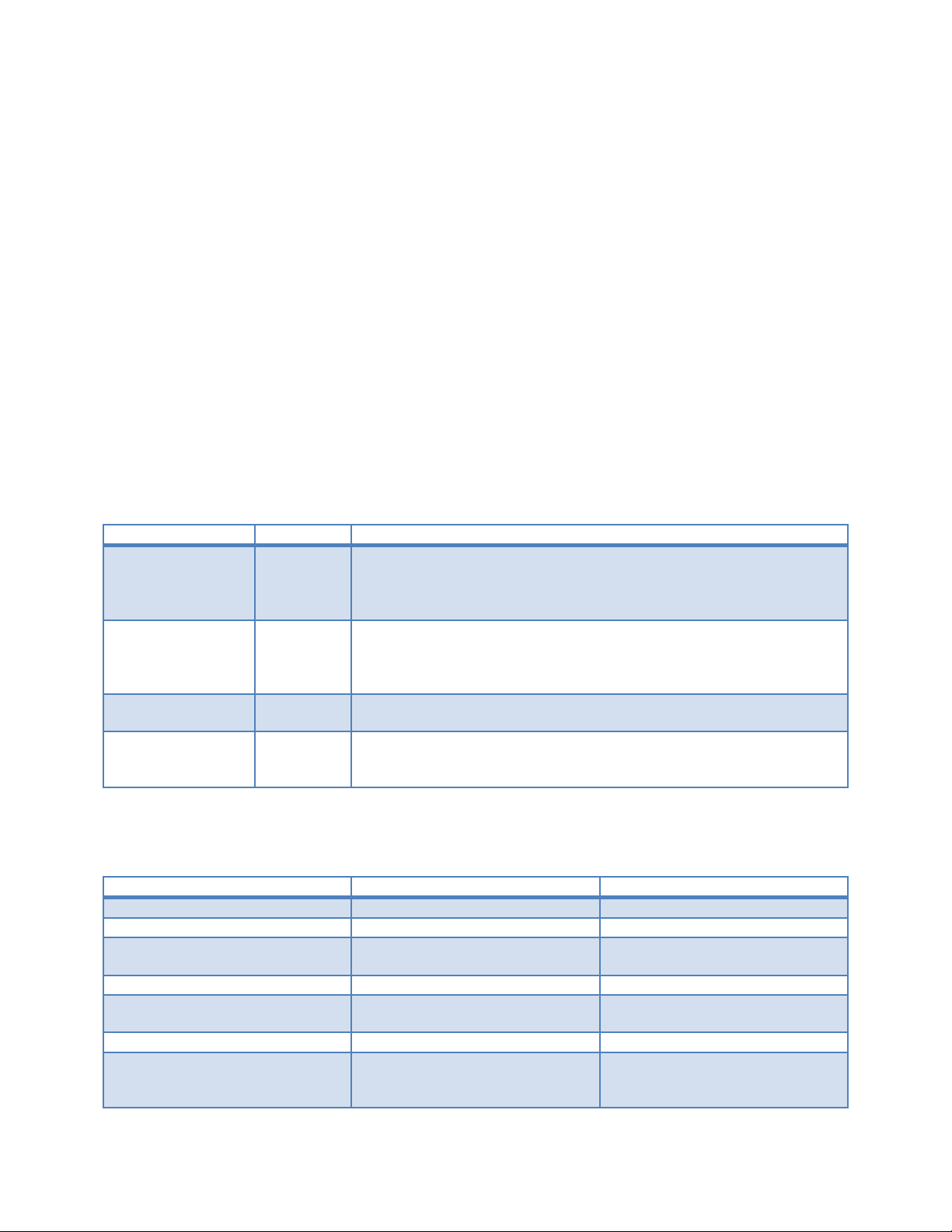
Table 1. Quick Reference R810, R910, and M910 Memory Guide
Mixed Ranks Yes DIMMs of different Ranks can be mixe d . The first slot of each
channel populated (first two white tab DIMM slots on each memory
buffer: A1, A2, A3, and A4) must be populated with the highest
ranked DIMM.
1 GB RDIMM in A1 and A2 implies that A3 and A4 would need to be 1
GB RDIMMs also. DIMM slots A5, A6, A7, and A8 could be a different
capacity and rank.
Yes Nehalem EX Architecture will support a maximum memory spee d of
1066 MTs.
vendor mix. Where possible, Dell recommends using the same DIMM
manufacturer.
Note: Only RDIMMS are supported with Intel 7500 and 6500 series processors.
Table 2. Quick Comparison Intel Xeon 5500-5600 Series to Intel Xeon 7500-6500
Yes Yes
the same frequency
1 2
3 2
(Speed shown is for top
bin…may be slower for down-
1066 MTs (2 DPC)
800 MTs (3 DPC)
(4 SMI Buses/8 DDR3 Channels)
(Same speed for SR, DR, or QR
DIMMs)
Page 3
Page 6

PowerEdge 11th Generation Servers: R810, R910, and M910 Memory Guidance
bin SKUs)
(Slower with QR DIMMs)
Minimum memory populat ion
Hemisphere Mode
No
Yes
Memory RAS Features
1 DIMM 2 DIMMs
(must populate with identical
DIMM pairs)
ECC, DIMM Sparing, Lock-step,
Mirroring, x4 or x8 SDDC
Enhanced ECC, DIMM sparing,
Lock-step, Mirroring, x4 or x8
SDDC, Rank sparing
PowerEdge R810 and M910
The R810 and M910 servers utilize DDR3 memory providing a high performance, high-speed memory
interface capable of low latency response and high throughput. The R810 and M910 support Registered
DDR3 DIMMs (RDIMMs) only.
The R810 and M910 utilize Intel Xeon 7500 and 6500 series processors that have four SMI channels for
each socket. Each of those memory controllers then has two SMI channels that connect to the Intel
7500 Scalable Memory Buffer.
The DDR3 memory interface consists of eight Intel 7500 Scalable Memory Buffers (two per socket), each
of which has two DDR3 memory chan nels. Each channel supports up to two RDIMMs for
single/dual/quad rank. By l imiting to two DIMMs per DDR channel, the system can support quad-rank
DIMMs at 1066 MTs. The R810 and M910 support a maximum of 32 DIMMS with four SMI channels per
socket, two Intel 7500 Scalable Memory Buffers per SMI channel, and two DDR3 channels per memory
buffer supporting two DIMMs each.
FlexMem Bridge Technology
In a four-CPU configuration, the R810 and M910 use only one memory controller per CPU. This single
controller connects to two memory buffers via SMI links. Each memory buffer in turn connects to four
DDR3 DIMMs with a total of 32 DIMMs accessible. In a two-CPU configuration, normally this would mean
that only four memory buffers are connected; therefore, a total of only 16 D IMMs are accessible.
To overcome this limitation w it h two CPUs, the R810 and M910 use a pass-through, called the FlexMem
Bridge, in the sockets without CPUs (CPU 3 and CPU 4). This allows CPU 1 and CPU 2 to connect to the
memory of their respective adjacent sockets (CPU 3 and CPU 4) and access the additional 16 DIMMs.
The FlexMem Bridge provides the following:
• Two pass-through links for SMI
• One pass-through link for QPI
• The pass-through SMI links connect the two installed CPUs to additional Intel 7500 Scalable
Memory Buffers; therefore, the CPUs will have the following memory attached:
• CPU 1 will have access to DIMMs A1-A8 and to DIMMs C1-C8 (those normally associate d with
CPU 3)
• CPU 2 will have access to DIMMs B1-B8 and to DIMMs D1-D8 (those normally associated with
CPU 4)
Page 4
Page 7

PowerEdge 11th Generation Servers: R810, R910, and M910 Memory Guidance
Figure 1. FlexMem Bridge Illustration
Page 5
Page 8

PowerEdge 11th Generation Servers: R810, R910, and M910 Memory Guidance
Figure 2. R810 and M910 Series Servers Memory Illustration
Note: This illustration is not a technical schematic of a motherboard. DIMMs A1-A8 correspond to CPU
1, DIMMs B1-B8 correspond to CPU 2, DIMMs C1-C8 correspond to CPU 3, and DIMMs D1-D8 correspond to
CPU 4.
PowerEdge R910
The R910 utilizes DDR3 memory providing a high performance, high-speed memory interface capable of
low latency response and high throughput. The R910 supports RDIMMs only.
The R910 utilizes Intel Xeon 7500 series processors that have one memory controller hub and two
integrated memory controllers. Each of those memory controllers has two SMI channels that connect to
the Intel 7500 Scalable Memory Buffer.
The DDR3 memory interface consists of 16 Intel 7500 Scalable Memory Buffers, each o f which has two
DDR3 memory channels. Each channel supports up to two RDIMMs (single/dual/quad-rank). By limiting
to two DIMMs per DDR channel, the system can support DIMMs running at 1066 MTs.
Page 6
Page 9

PowerEdge 11th Generation Servers: R810, R910, and M910 Memory Guidance
The R910 has eight memory risers; each memory riser has t wo Millbrook memory buffers and eight
DIMM slots.
Figure 3. R910 Series Servers Memory Illustration
Note: This illustration is not a technical schematic of a motherboard. DIMMs in Risers A and B
correspond to CPU 1, DIMMs in Risers C an d D correspond to CPU 2, DIMMs in R ise rs E and F correspond
to CPU 3, and DIMMs in Risers G and H correspond to CPU 4. A CPU must be present to populate the
riser. A system can operat e with only one riser per CPU.
Optimizing Memory Performance for Intel Xeon 7500 and 6500 Series Processors
Intel Xeon 7500 and 6500 Series processors support a maximum memory performance of
1066 MTs.
Best Performance
2 DIMMS per Memory Buffer Channel, all memory controllers populated equally with 64 DIMMs and 8
Memory Risers (R910) (see Figure 4) or 32 identical DIMMs (R810, M910) (see Figure 5), highest
bandwidth and lowest latency
Better Perfo rmance
1 DIMM per Memory Buffer Channel, all memory controllers populated equally with 32 DIMMs and 8
Memory Risers (R910) (see Figure 6) or 16 identical DIMMS (R810, M910) (see Figure 7), slight bandwidth
decrease
Page 7
Page 10

PowerEdge 11th Generation Servers: R810, R910, and M910 Memory Guidance
Xeon X7560, 8C
Xeon X7550, 8C
Xeon E7540, 6C
Xeon L7555, 8C
Xeon L7545, 6C
Xeon E7530, 6C
Xeon E7520, 4C
Good Performa nce
2 DIMMS per Memory Buffer Channel, all memory controllers populated equally with 32 DIMMs and 4
Memory Risers (R910), lower maximum bandwidth, higher latency
1 DIMM per Memory Buffer Channel, all memory controllers populated equally with 16 DIMMs and 4
Memory Risers (R910), lower maximum bandwidth, higher latency
Note: Mixed DIMM capacity is supporte d. The recommendation is to populate memory controllers
equally and always pair DIMMs identically.
Figure 4. R910 Relative Memory Bandwidth for the Intel Xeon 7500 Series Processors
2.26 GHz
6.40 QPI
1066 MTs
2.00 GHz
6.40 QPI
1066 MTs
2.00 GHz
6.40 QPI
1066 MTs
1.86 GHz
5.86 QPI
1066 MTs
1.86 GHz
5.86 QPI
978 MTs
1.86 GHz
5.86 QPI
978 MTs
1.86 GHz
4.80 QPI
800 MTs
Page 8
Page 11

PowerEdge 11th Generation Servers: R810, R910, and M910 Memory Guidance
Figure 5. M910/R810 Relative Memory Bandwidth for the Intel Xeon 6500 and 7500
Series Processors
Xeon X7560, 8C
2.26 GHz
6.40 QPI
1066 MTs
Xeon E7540, 6C
2.00 GHz
6.40 QPI
1066 MTs
Xeon L7555, 8C
1.86 GHz
5.86 QPI
1066 MTs
Xeon L7545, 6C
1.86 GHz
5.86 QPI
978 MTs
Xeon X6550, 8C
2.00 GHz
6.40 QPI
1066 MTs
Xeon E6540, 6C
2.00 GHz
6.40 QPI
1066 MTs
Xeon E6510, 4C
1.73 GHz
4.80 QPI
800 MTs
Page 9
Page 12

PowerEdge 11th Generation Servers: R810, R910, and M910 Memory Guidance
Figure 6. R910 With 64 Identical DIMMs, 2 DIMMs Per Channel
Page 10
Page 13

PowerEdge 11th Generation Servers: R810, R910, and M910 Memory Guidance
Figure 7. R810 or M910 With 32 Identical DIMMs, 2 DIMMs Per Channel
Page 11
Page 14

PowerEdge 11th Generation Servers: R810, R910, and M910 Memory Guidance
Figure 8. R910 With 32 Identical DIMMs, 1 DIMM Per Channel
Page 12
Page 15

PowerEdge 11th Generation Servers: R810, R910, and M910 Memory Guidance
Figure 9. R810 and M910 With 16 Identical DIMMs, 1 DIMM Per Channel
Memory RAS Features
Sparing
For Rank sparing, one rank on each lock-step Millbrook pair will be reserved as a spare, and in the
event that another rank exceeds a threshold of correctable ECC errors, the “failing” rank will be
copied to the spare. After that operat ion is complete, the failed rank will be disabled.
For Dual rank DIMMs: 1 rank within a D IMM is used as a spare
For Quad rank DIMMs: 1 or 2 ranks w ithin a DIMM are used as a spare
Page 13
Page 16

PowerEdge 11th Generation Servers: R810, R910, and M910 Memory Guidance
Figure 10. Example of Sparing for Dual Rank and Quad Rank DIMMs
Mirroring
For mirroring, the R910 will support 2P/4P configurations for >= 64 GB only. The R810 and M910 support
mirroring in 32 DIMM configurations >= 64 GB only. When mirrori ng is enabled, only half of the physical
memory will be visible to the system. A full copy of the memory is maintained, and, in the event of an
uncorrectable error, the syst e m will switch over to the mirrored copy. The R910 uses intra-socket
mirroring.
Page 14
Page 17

PowerEdge 11th Generation Servers: R810, R910, and M910 Memory Guidance
Figure 11. Example of R910 Intra-Socket Mirroring
Note: A1, A3 are mirrored to A2, A4; B1, B3 are mirrored to B2, B4; C1, C3 are mirrored to C2, C4;
D1, D3 are mirrored to D2, D4; E1, E3 are mirrored to E2, E4; F1, F3 are mirrored to F2, F4; G1, G 3 are
mirrored to G2, G4; H1, H3 are mirrored to H2, H4.
For mirroring, the R810 will support 2P/4P configurations with 32 DIMMs only. When mirroring is
enabled, only half of the physic al memory will be visible to the system software. A full copy of the
memory is maintained, and, in the event of an uncorrectable error, the system will switch over to the
mirrored copy. In 2P mode, the mirroring will be inter-node with hemisphere mode enabled.
Page 15
Page 18

PowerEdge 11th Generation Servers: R810, R910, and M910 Memory Guidance
Figure 12. Example of R810 and M910 Intra-Node Mirroring
For 4P, the R810 will also support mirroring in the inter-socket mode. In this 4P case, the memory on
CPU 1 will be mirrored with mem or y on CPU 3, while memory on CPU 2 is mirrored with memory on
CPU 4.
Page 16
Page 19

PowerEdge 11th Generation Servers: R810, R910, and M910 Memory Guidance
Intel Xeon Processor
Max Memory Speed
130 Watt X7560*
1066 MTs
130 Watt X7542*
978 MTs
105 Watt E7530**
978 MTs
95 Watt E7520
800 MTs
95 Watt L7545
978 MTs
105 Watt X6540***
978 MTs
105 Watt E6510***
800 MTs
Figure 13. Example of R810 and M910 Inter-Socket Mirroring
Table 3. Intel Xeon 7500/6500 Series Processor Performance and Max Memory Speed
130 Watt X7550*
105 Watt E7540
95 Watt L7555
130 Watt X6550***
1066 MTs
1066 MTs
978 MTs
1066 MTs
Note: * X7550 will not be offered on the R810 or M910. The R810 and M910 will support only two 130
Watt processors. **E7530 will not be offered on the R810 or M910. ***All 6500 series processors are only
2-socket capable, cannot be upgraded to 4-socket capability.
Page 17
 Loading...