

Page 1

Dell EqualLogic PS4210 Storage Arrays
Hardware Owner's Manual
Version 1.0
Page 2

© Copyright 2014 Dell Inc. All rights reserved.
Dell™ and EqualLogic® are trademarks of Dell Inc. All trademarks and registered trademarks mentioned herein
are the property of their respective owners.
Information in this document is subject to change without notice.
Reproduction of this material in any manner whatsoever without the written permission of Dell is strictly
forbidden.
Published: November 2014
Part Number: 110-6215-EN-A01
Page 3

Table of Contents
Preface
1 Basic Storage Array Information
About the PS4210 Array 1
Recommended Tools 1
Protecting Hardware 1
Back-Panel Features and Indicators 4
Shutting Down and Restarting an Array 4
2 Maintaining Drives
About Drive Types 7
Identifying Failed Drives 7
Interpreting Drive LEDs 7
Array Behavior When a Drive Fails 8
Drive Handling Requirements 9
Drive Installation Guidelines and Restrictions 9
3 Maintaining Control Modules
Control Module Features 15
Replacing a Control Module 20
Replacing the MicroSD Card 24
Battery Replacement 26
Shipping Requirements
Advanced Networking Options 29
4 Maintaining Power Supply and Cooling Modules
About Power Supplies 31
Identifying Power Supply Failures 31
5 Troubleshooting Your Array
Index
v
1
7
15
27
31
35
37
iii
Page 4

Table of Contents
iv
Page 5

Preface
This manual describes how to install Dell™ EqualLogic® PS4210 storage array hardware, configure the
software, and start using the iSCSI SAN array.
With one or more PS Series storage arrays, you can create a PS Series group—a self-managing, iSCSI storage
area network (SAN) that is affordable and easy to use, regardless of scale.
Audience
The information in this guide is intended for the administrators responsible for installing array hardware.
Administrators are not required to have extensive network or storage system experience. However, it is helpful
to understand:
• Basic networking concepts
• Current network environment
• User disk storage requirements
• RAID configurations
• Disk storage management
Although this manual provides examples of using PS Series arrays in some common network configurations,
detailed information about setting up a network is beyond its scope.
Related Documentation
For detailed information about FS Series appliances, PS Series arrays, groups, volumes, array software, and host
software, log in to the Documentation page at the customer support site (eqlsupport.dell.com).
Dell EqualLogic Storage Solutions
To learn more about Dell EqualLogic products and new releases, visit the Dell EqualLogic Tech Center site:
delltechcenter.com/page/EqualLogic. Here you can also see articles, demos, online discussions, and more details
about the benefits of our product family.
Contacting Dell
Dell provides several online and telephone-based support and service options. Availability varies by country and
product, and some services might not be available in your area.
To contact Dell EqualLogic Technical Support by phone, if you are located in the United States, call 800-945-
3355. For a listing of International Dell EqualLogic support numbers, visit dell.com/support/home. From this
website, select your country from the drop-down list in the upper-left corner of the screen. If you do not have
access to an Internet connection, contact information is printed on your invoice, packing slip, bill, or Dell product
catalog.
Use the following procedure to register for an EqualLogic customer support account, to log cases via the web,
and to obtain software updates, further documentation, and resources.
1. Visit eqlsupport.dell.com or the Dell support URL specified in information provided with the Dell product.
2. Select the required service. Click the Contact Us link, or select the Dell support service from the list of
services provided.
3. Choose your preferred method of contacting Dell support, such as email or telephone.
v
Page 6
Preface
Online Services
You can learn about Dell products and services by visiting dell.com (or the URL specified in any Dell product
information).
Warranty Information
The PS4210 array warranty is included in the shipping box. For information about registering a warranty, visit
onlineregister.com/dell.
Note, Caution, and Warning Symbols
A NOTE symbol indicates important information that helps you make better use of your hardware or software.
A CAUTION symbol indicates potential damage to hardware or loss of data if instructions are not followed.
A WARNING symbol indicates a potential for property damage, personal injury, or death.
vi
Page 7
1 Basic Storage Array Information
This chapter includes information about the location and basic operation of the replaceable components in a
storage array, tools and equipment you will need, protecting hardware from electrostatic discharge, and power
on and off operations.
About the PS4210 Array
The PS4210 is a PS4x10 10GbE class EqualLogic® PS Series array that continues the focus by Dell™ on
industry-standard features and capabilities for the midrange iSCSI SAN market.
PS4210 Features
The PS4210 array is available in a 2U chassis with up to 24 2.5-inch drives, or 12 3.5-inch drives.
Features of the PS4210 array include:
• Two hot-swappable Type 19 control modules, which contain increased memory (8GB per controller) and a
more powerful processor than previous generation controllers
• Ethernet ports:
– Two pairs of 10Gb/s dual-media interfaces (10GBASE-T/SFP+)
– Ability to auto-negotiate down to 1Gb/s interface (10GBASE-T ports only)
• Support for ReadyRails™ II
Recommended Tools
You will need the following items to perform the procedures in this section:
• Bezel key
• Wrist grounding strap
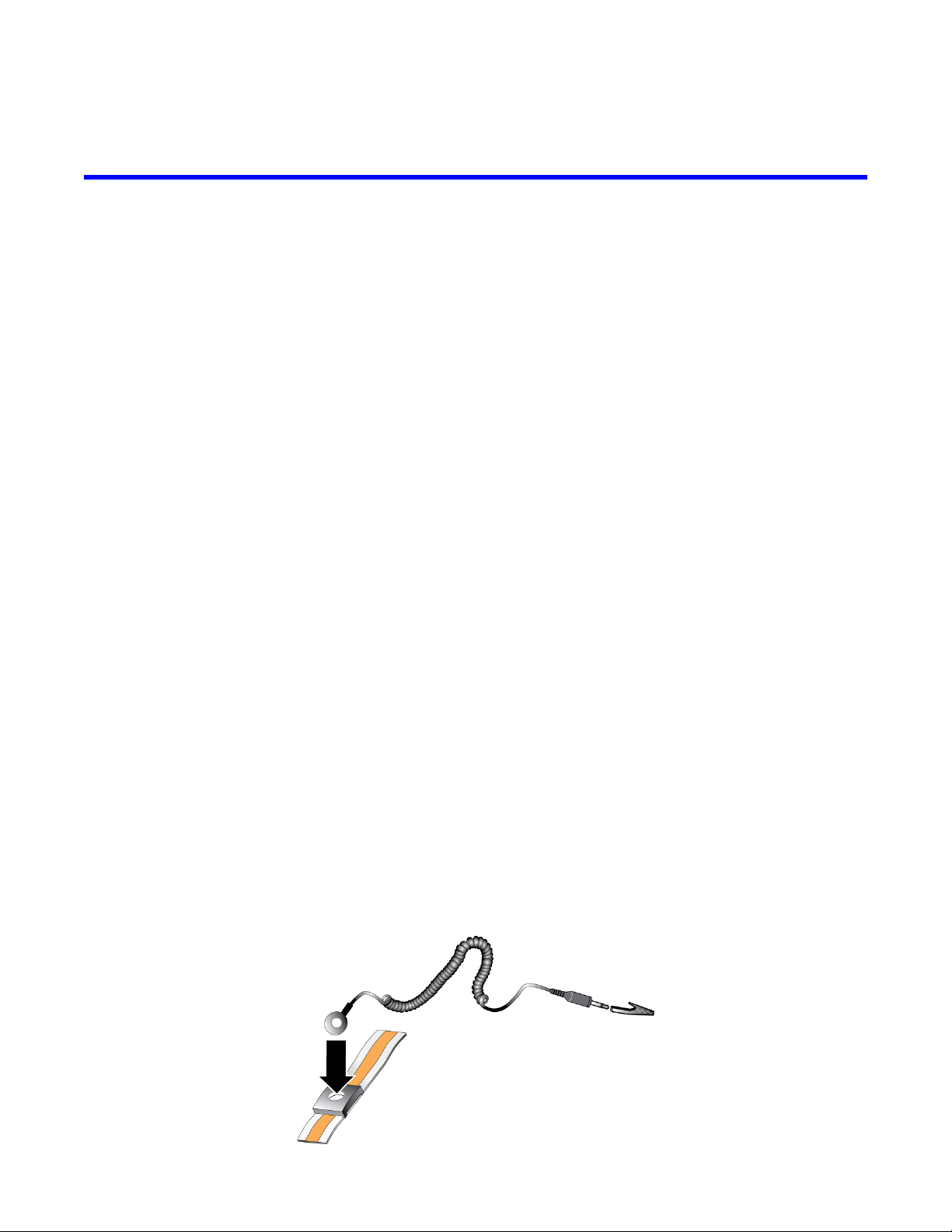
Protecting Hardware
Protect your PS Series array from electrostatic discharge. When handling array hardware, use an electrostatic
wrist strap or a similar form of protection. To use a wrist strap:
1. Connect the steel snap on the coil cord to the stud on the elastic band. See Figure 1.
Figure 1: Using an Electrostatic Wrist Strap
1
Page 8
PS4210 Hardware Owner's Manual
2. Fit the band tightly around your wrist.
3. Connect the band to ground. You can either plug the banana connector into a matching grounded receptacle,
or attach it to the matching alligator clip and connect the clip to a grounded device. Examples of an
appropriate ground would be an ESD mat or the metal frame of a grounded piece of equipment.
1 Basic Storage Array Information
Array Bezel
The bezel is an optional trim panel that attaches to the front of the array to ensure the physical security of the
array. You must remove the bezel to access and maintain the drives.
The bezel has a label that identifies the array model number.
Removing the Bezel
The steps for removing the bezel are the same for all array models:
1. Using the bezel key, unlock the bezel.
2. Holding the bezel, lift the latch on the left side of the bezel and swing the left side away from the array.
3. Lift the right side of the bezel off the right side of the array.
4. Set the bezel aside.
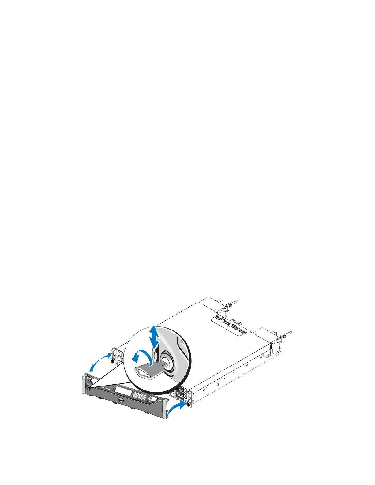
Installing the Bezel
The steps for installing the bezel are the same for all array models:
1. Hook the right end of the bezel onto the right side of the chassis.
2. Swing the left end of the bezel toward the left side of the chassis.
3. Press the bezel into place until the release latch closes.
4. Using the key provided, lock the bezel and store the key in a safe place as shown in Figure 2.
Figure 2: Installing the Bezel
2
Page 9
PS4210 Hardware Owner's Manual
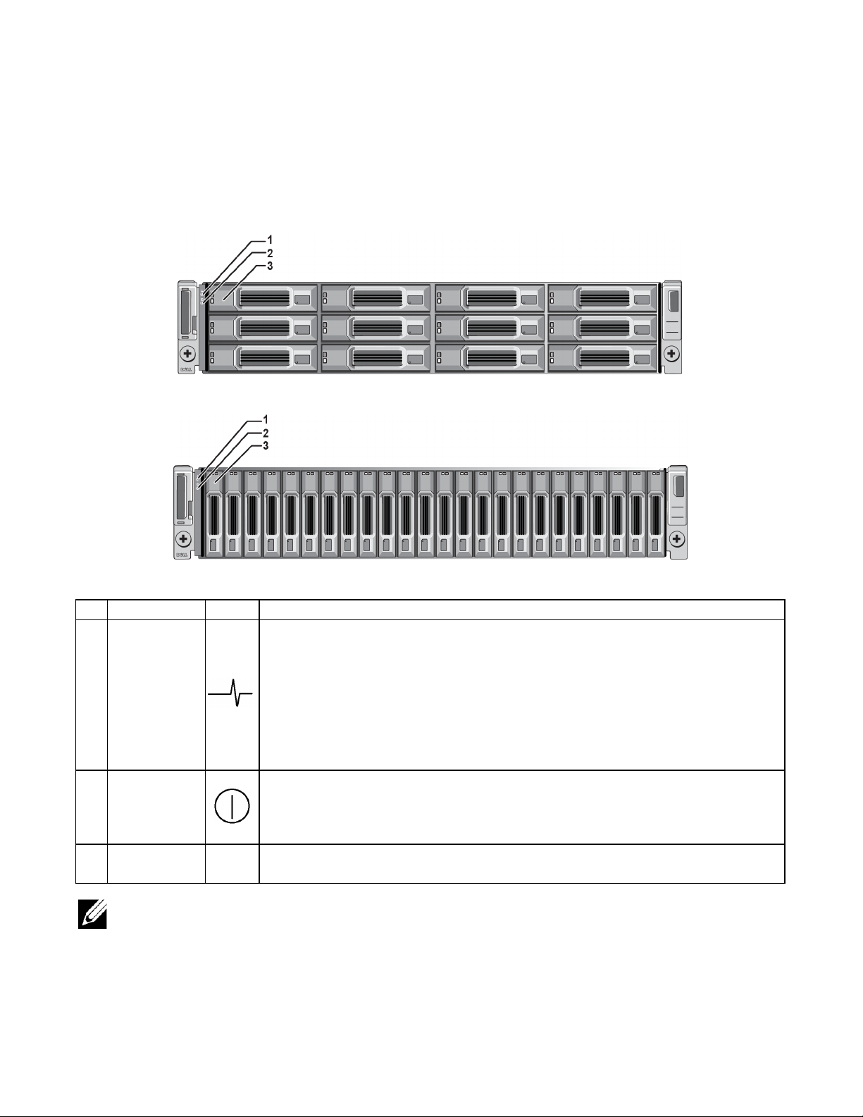
Front-Panel Features and Indicators
The front of a PS4210, without the bezel, is shown in Figure 3.
Table 1 describes the front-panel features.
Figure 3: Front-Panel Features and Indicators (3.5-inch Drives)
Figure 4: Front Panel Features and Indicators (2.5-inch Drives)
1 Basic Storage Array Information
Table 1: Front-Panel Feature Descriptions
Item Indicator Icon Description
The array status LED lights when the array power is on.
• Off—No power.
• Steady blue—Array status is OK.
Array status
1
LED
2 Power LED
Drive release
3
latch
The LEDs are part of a built-in chassis control panel that is not hot-swappable and can be replaced only by
support personnel. During the array power-up sequence, these LEDs will cycle through different states until the
array is fully started and the active control module has been determined.
None Enables you to remove a drive from the array.
• Slow blinking blue—Array status is Standby mode.
• Blinking blue—Administrator request to identify the array (see the Group Manager
online help).
• Steady amber—Critical status.
• Blinking amber—Warning.
The power LED is ON when at least one power supply is supplying power to the array.
• Off—No power, or the array is in Standby mode.
• Steady green—Array has at least one power supply providing power, and array is
not in Standby mode.
3
Page 10
PS4210 Hardware Owner's Manual
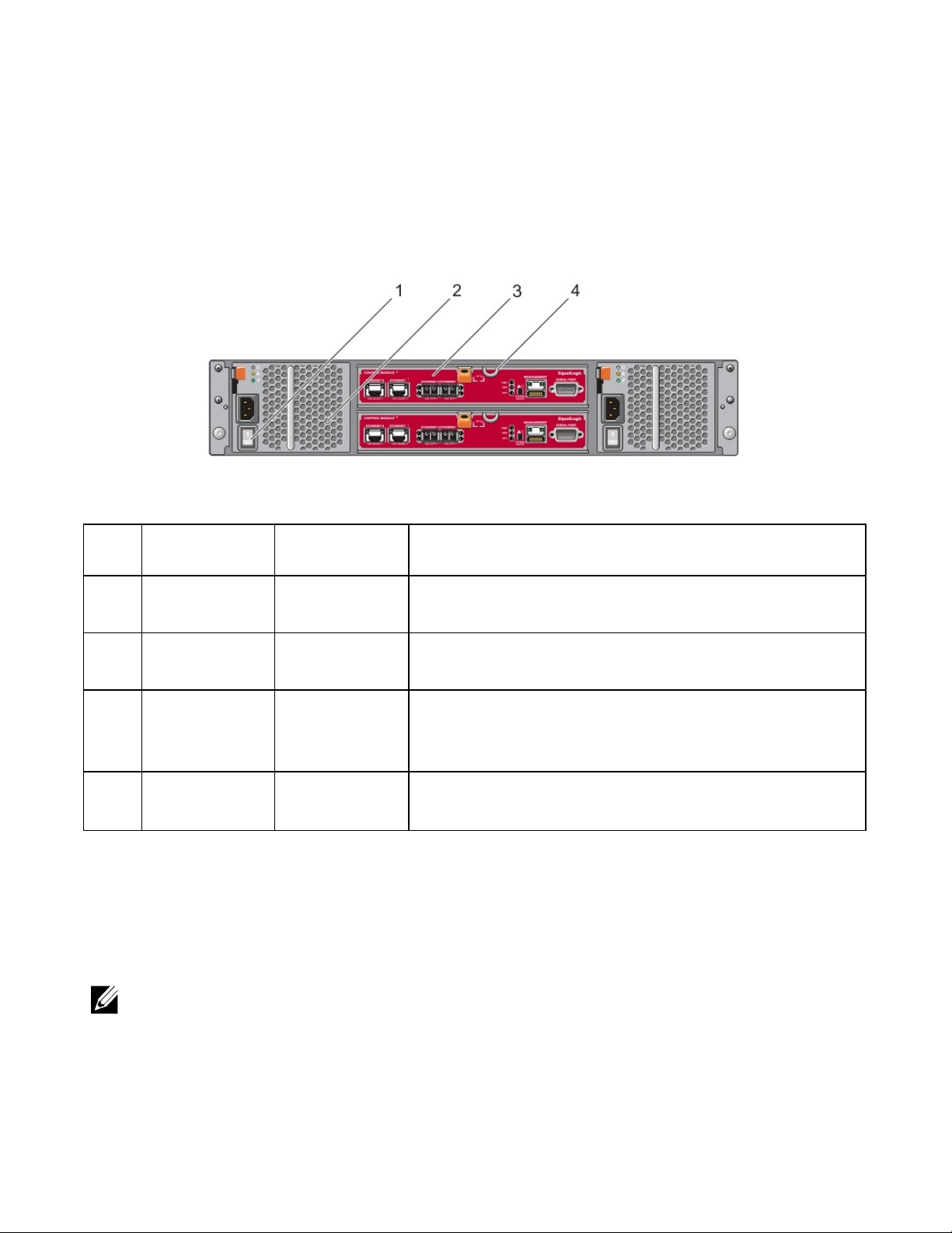
Back-Panel Features and Indicators
The back of a PS4210 is shown in Figure 5.
Table 2 describes the back-panel features.
Figure 5: Back-Panel Features
1 Basic Storage Array Information
Table 2: Array Back-Panel Features
Item Feature Identifier Description
1 Power switch None
2
3 Control module
4
Power supply unit
(PSU)
Control module
release lever
PSU0 (left)
PSU1 (right)
CM0 (top)
CM1 (bottom)
None
The power switch controls the power supply output to the array. One
switch on each power supply.
Power supply and cooling fan module for array.
The control module provides:
• Connection to a data path between the array and the applications
using the storage
• Array management functions for your array
Enables you to remove the control module from the array.
Shutting Down and Restarting an Array
A PS Series array includes redundant, hot-swappable drives, power supplies, and control modules (in a dual
control module array). You can remove a redundant component without affecting operation if a functioning
component is available. Otherwise, Dell recommends that you cleanly shut down the array and turn off power
before removing a component.
When an array is shut down, any volumes with data on the array will be set offline until the array is successfully
restarted. Being offline affects initiators that are connected to the volumes.
Array shutdown procedure
1. Connect to the array in one of the following ways:
4
Page 11

PS4210 Hardware Owner's Manual
1 Basic Storage Array Information
• Use telnet or SSH to connect to a functioning IP address assigned to a network interface on the array.
Do not connect to the group IP address.
• Use the null modem cable, shipped with the array, to connect the serial port on the active control module
(ACT LED is green) to a console or a computer running a terminal emulator.
Make sure the serial line characteristics are as follows:
• 9600 baud
• One STOP bit
• No parity
• 8 data bits
• No flow control
2. Log in to an account with read-write access, such as the grpadmin account.
3. Enter the shutdown command, as follows:
login: grpadmin
Password:
Welcome to Group Manager
Copyright 2001-2014 Dell Inc.
group1> shutdown
If you are using a serial connection to shut down an array, it is safe to turn off power when the “press any key”
message appears. (Pressing any key will restart both control modules.)
If you are using a network connection, the session will be disconnected before the array is fully shut down.
Confirm that the ACT LED on each control module is off (not lit) before turning off power to the array.
After performing array maintenance, you can turn on power to the array. When the array restart completes, the
member and volumes will be set online.
5
Page 12

PS4210 Hardware Owner's Manual
1 Basic Storage Array Information
6
Page 13
2 Maintaining Drives
You can replace a failed drive while the array remains running.
About Drive Types
Depending on your configuration, your array supports up to 24 2.5-inch SAS and SSD drives or up to 12 3.5-inch
SAS or NL-SAS drives in internal drive bays.
Drives are connected to a backplane through drive carriers and are hot-swappable.
Drives are supplied in a carrier that is keyed to fit into specific array models, and cannot be installed in other
Dell arrays, or arrays not from Dell Inc.
Dell uses specially qualified and tested hard drives for its EqualLogic storage systems, and manages hard drive
quality and firmware only for those drives. As a result, only Dell-provided hard drives are supported by PS Series
arrays. Attempts to use other, unapproved hard drives in the PS4210 array will not be successful.
Identifying Failed Drives
A drive failure is indicated by:
• LEDs on the drive.
• A message on the console, in the event log, or in the Group Manager Alarms panel.
• Indications in the Group Manager Member Disks window or the CLI member select show disks command
output.
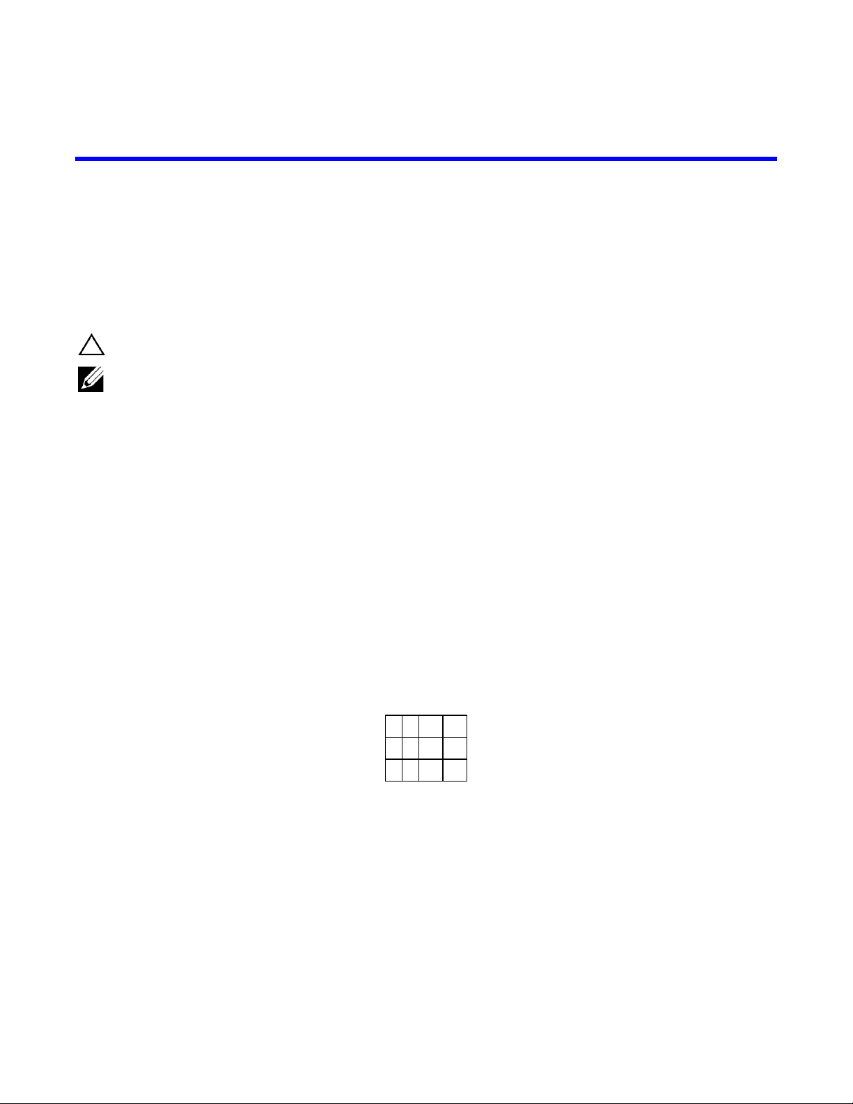
Behind the bezel, arrays have a label showing the drive numbering for that specific array model:
• In arrays with 2.5-inch drives (installed vertically in a row), the drives are numbered 0–23, left to right.
• In arrays with 3.5-inch drives (installed horizontally), the drives are numbered from left to right and top to
bottom, starting with 0 on the upper left side. Table 3 shows the drive order for the 3.5-inch drives.
Table 3: 3.5-inch Drive Numbering
0 1 2 3
4 5 6 7
8 9 10 11
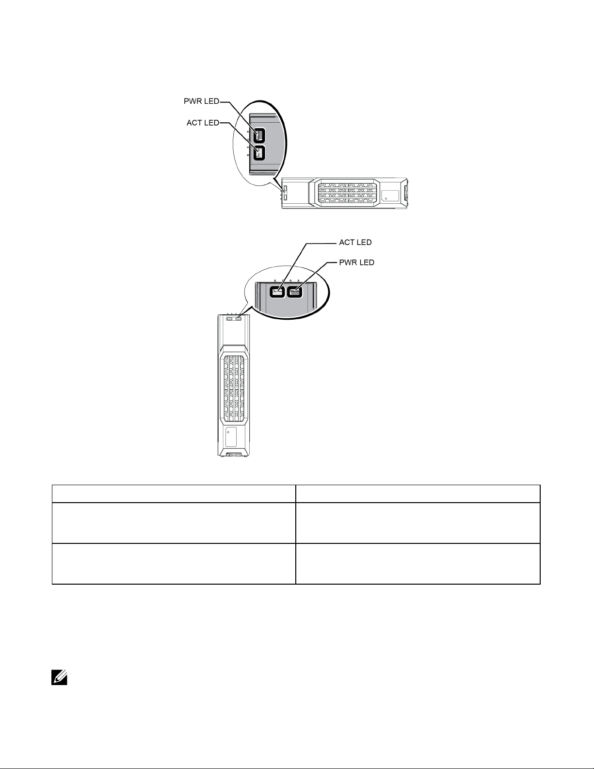
Interpreting Drive LEDs
The LEDs on a 3.5-inch drive are shown in Figure 6. The LEDs on a 2.5-inch drive are shown in Figure 7. Drive
LED states are described in Table 4.
7
Page 14
PS4210 Hardware Owner's Manual
2 Maintaining Drives
Figure 6: LEDs on 3.5-inch Drives
Figure 7: LEDs on 2.5-inch Drives
Table 4: Drive LED States
Description Indicator States
Blinking green: Drive is busy
Drive activity indicator (ACT LED)
Drive status indicator (PWR LED)
Steady green: No drive activity
Off: Drive is a spare, and spun down
Green: Drive OK
Amber: Drive failed
Off: No power to drive
Array Behavior When a Drive Fails
In firmware version 5.2.5 and later, Dell implemented a copy-to-spare operation to replace failing drives. This
operation can, in many cases, improve the performance of the drive replacement process by avoiding a full
RAID rebuild and as a result can provide better reliability.
If a drive fails, replace it. Do not reinstall it in the array.
8
Page 15

PS4210 Hardware Owner's Manual
2 Maintaining Drives
If a Spare Drive Is Not Available
If a spare drive is not available, the RAID set will become degraded and performance might be impaired.
However, a RAID 6 set can survive two simultaneous drive failures.
If a spare drive is not available and the failed drive is in a RAID set that is already degraded, data might be lost
and must be recovered from a backup.
Drive Handling Requirements
Handle drives as follows:
• Protect drives from electrostatic discharge. Wear an electrostatic wrist strap when handling a drive. See
Protecting Hardware on page 1.
• Store drives properly. Store replacement drives in the packaging in which they were shipped. Do not stack
drives or place anything on top of a drive.
• Handle drives carefully. Hold a drive only by the plastic part of the carrier or the handle. Do not drop, jolt,
or force a drive into a slot.
• Warm replacement drives to room temperature before installation. For example, let a drive sit overnight
before installing it in an array.
• Do not remove a functioning drive (other than a spare) from an array. If the drive is not a spare, the RAID
set might become degraded. If you remove a spare, replace the drive as soon as possible.
• Do not leave drive slots empty. Each drive slot in an array must contain a drive assembly or a blank carrier.
Operating an array with an empty slot will void your warranty and support contract.
• Do not remove a drive from its carrier. This action will void your warranty and support contract.
• Keep the shipping material. Return a failed drive to your array support provider in the packaging in which
the replacement drive was shipped. Shipping drives in unauthorized packaging might void your warranty.
Drive Installation Guidelines and Restrictions
• Replace a failed drive as soon as possible, to provide the highest availability.
• Install only drives of the same type, speed, and spin rate in an array.
• You can use drives of different capacities in the same array. However, the smallest drive in the array will
determine how much space can be used on each drive. For example, if the smallest drive is 400GB, only
400GB of space will be available for use on each drive.
• Make sure the drive is oriented in the correct position for the array model. See Front-Panel Features and
Indicators on page 3.
• Insert a drive fully in the chassis before pushing in the handle.
• When correctly installed, a drive will be flush with the front of the array. If the drive is protruding from the
array, reinstall the drive.
• After installation, make sure the drive power LED is green or flashing green. See Identifying Failed Drives
on page 7.
• A two-minute delay occurs between the time you insert a drive and the time the drive is automatically
configured into a RAID set. This time interval allows multiple drives to be simultaneously configured in an
array, which is more efficient than installing a single drive, configuring it, and then repeating the process.
9
Page 16

PS4210 Hardware Owner's Manual
For example, when you install a drive, the timer starts. If you install another drive before 2 minutes have
elapsed, the timer is restarted. If no other drives are installed, the drive is configured after a delay of 2 minutes.
• If you install a drive during RAID reconstruction or verification, the new drive will not be configured until
the operation completes.
2 Maintaining Drives
Removing a 2.5-inch Drive
1. Remove the bezel. See Removing the Bezel on page 2.
2. Press the release button (callout 1 in Figure 8). The drive latch opens and the drive emerges partway from
the array (callout 2).
3. Pull the drive out by the handle until it is free of the drive bay (callout 3).
Figure 8: Removing a 2.5-Inch Drive
10
Page 17

PS4210 Hardware Owner's Manual
2 Maintaining Drives
Installing a 2.5-inch Drive
The 2.5-inch drives are installed vertically, with the drive release latch on the top and the drive label on the
bottom.
1. Wear electrostatic protection when handling a drive. See Protecting Hardware on page 1.
2. Open the drive release latch.
3. Hold the drive by the carrier and slide the drive most of the way into a slot (callout 1 in Figure 9).
4. Push the drive completely into the slot (callout 2). The drive handle will begin to close onto the drive (callout
3).
5. Push in the handle until you hear a click (callout 4).
Figure 9: Installing a 2.5-inch Drive
11
Page 18

PS4210 Hardware Owner's Manual
Verify that the new drive is operational by examining the LEDs on the front panel, as described in Interpreting
Drive LEDs on page 7. In addition, examine the GUI Member Disks window and the CLI member select show
disks command output.
2 Maintaining Drives
Removing a 3.5-inch Drive
1. Remove the bezel. See Removing the Bezel on page 2.
2. Press the release button (callout 1 in Figure 10). The drive latch opens and the drive emerges partway from
the array (callout 2).
3. Pull the drive out by the handle until it is free of the drive bay (callout 3).
Figure 10: Removing a 3.5-Inch Drive
12
Page 19

PS4210 Hardware Owner's Manual
2 Maintaining Drives
Installing a 3.5-inch Drive
The 3.5-inch drives are installed horizontally, with the drive release latch to the left and the drive label to the
right.
1. Wear electrostatic protection when handling a drive. See Protecting Hardware on page 1.
2. Open the drive release latch.
3. Hold the drive by the carrier and slide the drive most of the way into a slot (callout 1 in Figure 11).
4. Push the drive completely into the slot (callout 2). The drive handle will begin to close onto the drive (callout
3).
5. Push in the handle until you hear a click (callout 4).
Figure 11: Installing a 3.5-inch Drive
13
Page 20

PS4210 Hardware Owner's Manual
Verify that the new drive is operational by examining the LEDs on the front panel, as described in Interpreting
Drive LEDs on page 7. In addition, examine the GUI Member Disks window and the CLI member select show
disks command output.
2 Maintaining Drives
Removing a Drive Blank
To maintain proper system cooling, all empty drive slots must have drive blanks installed.
1. Remove the bezel. See Removing the Bezel on page 2.
2. Press the release tab and slide the drive blank out until it is free of the drive slot. See Figure 12 or Figure 13
and the callouts in.Table 5.
Figure 12: Removing and Installing a 3.5-Inch Hard-Drive Blank
Figure 13: Removing and Installing a 2.5-Inch Hard-Drive Blank
Table 5: Hard Drive Blank Callout Values
Item Description
1 Drive blank
2 Release tab
Installing a Drive Blank
1. Remove the bezel. See Removing the Bezel on page 2.
2. Insert the drive blank into the drive bay until the blank is fully seated.
3. Attach the bezel.
14
Page 21

3 Maintaining Control Modules
Different PS Series array models contain different control module types. The combination of chassis type,
control module pair, and drives determines the PS Series array model number.
The control modules in a PS Series array contain the PS Series firmware, which provides the Group Manager
GUI, the command line interface, and all the array and storage management functions and features.
Ideally, an array has two control modules (which must be of the same type) to avoid a single point of failure for
the array.
A PS4210 array includes two hot-swappable Type 19 control modules.
One functioning control module is required for array operation. You access control modules from the rear of the
array.
Control Module Features
The Type 19 control module includes:
• Two pairs of Ethernet ports with two shared LEDs indicating status and activity:
– One pair of 10GBASE-T ports, labeled Ethernet 0 and Ethernet 1
– One pair of SFP+ ports, labeled Ethernet 0 and Ethernet 1
Only one of two ports with the same numbered port can be used at a time. If both ports are attached to an
active switch, the control module will prefer to communicate over the SFP+ interface.
• One 10Mb/100Mbps port, labeled MANAGEMENT, for use only if you configure a management network.
The management port has two LEDs to indicate status and activity. See Configuring the Management Port
on page 29 for more information.
• A column of LEDs labeled PWR (power), ERR (error condition) and ACT (activity) that indicate the status
of the control module.
• A recessed button labeled STANDBY ON/OFF that allows you to quickly shut down the array in certain
circumstances. See About the Standby On/Off Button on page 19 for more information.
• One serial port (for use if no network access to the array is available).
• A field-replaceable microSD card containing the PS Series firmware. The microSD card is accessed from
the rear of the control module.
• A release button and latch to release the control module from the array for replacement. The release lever
has a switch that detects activation and prompts the array to save data to nonvolatile storage, thereby
protecting your data.
Do not mix control module types in an array. Always make sure both control modules are the same type and
color. See the latest PS Series Release Notes for information about other supported control modules.
About Control Module Configurations
While an array can run using only one control module, it is not recommended because this configuration creates
a single point of failure. If the control module fails and no other module can take over, all access to your
volumes stops until the failure is repaired or the control module is replaced.
15
Page 22

PS4210 Hardware Owner's Manual
Only one control module is active (providing disk access and serving network traffic) at one time. The secondary
(redundant) control module mirrors cache data from the active control module. If the active control module fails,
all functions of the primary controller transfer to the secondary.
3 Maintaining Control Modules
Dual Controller Configuration
A dual control module configuration eliminates a single point of failure in the array. If the active control module
fails, the secondary control module takes over automatically with no interruption of service. This automatic
transition gives you time to replace the failed control module while your volumes and data remain accessible.
In addition, a dual control module configuration supports a feature called vertical failover. An Ethernet port on
the active control module can fail over to the same Ethernet port on the secondary control module if a network
path fails. Figure 14 shows a recommended configuration for vertical failover.
Figure 14: Recommended Network Configuration to Support Vertical Failover
• If a network port is available for failover on either control module, but is not currently in use, its LEDs will
not be lit.
• Vertical failover is transparent to applications.
Interpreting Control Module LEDs
Control modules have the following LEDs:
16
Page 23

PS4210 Hardware Owner's Manual
3 Maintaining Control Modules
• The Ethernet ports and the Management port each have LEDs that indicate the port's status and activity. See
Table 6.
• Below the release latch is a column of three LEDs that indicate the status of the entire control module. See
Table 7.
Figure 15: Control Module LEDs
Table 6: Ethernet and Management Port LED Descriptions
Ethernet LED
Location
Top (Link)
Bottom (Act)
10GBASE-T
Ethernet
LED Location
Left (Link)
Right (Act)
SPF+ Ethernet
LED Location
Top (Link)
Bottom (Act)
Management
LED Location
Left (Link)
Right (Act)
State Description
Off
On (green)
Off
On (amber)
State
Off
On (green)
Off
On (amber)
State Description
Off
On (green)
Off
On (amber)
State Description
Off
On (green)
On (amber)
Off
On (blinking green)
No power or not connected to network.
Connected to network.
No power, not transmitting, or not receiving.
Transmitting or receiving.
Description
No power, not connected to network, or passive.
Connected to network.
No power, not transmitting, or not receiving.
Transmitting or receiving.
No power, not connected to network, or passive.
Connected to network.
No power, not transmitting, or not receiving.
Transmitting or receiving.
No power or not connected to network.
Connected to network (100mbit).
Connected to network (10mbit).
No power, not transmitting, or not receiving.
Transmitting or receiving.
17
Page 24

PS4210 Hardware Owner's Manual
Table 7: Control Module Status LED Descriptions
LED Name State Description
Off No power.
PWR
ERR
ACT
On (steady
green)
Off Normal operation or no power.
Steady red
Blinking red
Off
Steady green
Steady amber
Power/OK.
Array is starting up, in error condition, in Standby mode, or returning from Standby
mode.
Array is entering power standby mode because the Standby On/Off button was
pressed.
No power, secondary control module is not synchronized with active control module,
or error condition.
Active control module (serving network I/O).
Secondary control module. Cache is synchronized with active control module.
Identifying Control Module Failures
3 Maintaining Control Modules
You can identify a failure in a control module by:
• LEDs on the control module itself. See Interpreting Drive LEDs on page 7.
• Messages on the console, in the event log, or in the Group Manager GUI Alarms panel.
• Group Manager GUI and CLI output. The Member Controllers window or the member select show
controllers command output shows the control module status not installed.
When viewed from the rear of the array, CM0 is on the top and CM1 is on the bottom. See Front-Panel Features
and Indicators on page 3.
If a control module fails, contact your PS Series support provider for a replacement.
Understanding Failover Behavior
In a dual control module array, only one control module is active (processing network I/O and performing storage
functions) at one time. Each control module stores recently used data.
For redundancy, the cache on the secondary control module mirrors the data that is stored in the cache on the
active control module.
The active control module can use the network interfaces of the secondary control module for failover if a cable
is connected from the corresponding port on the secondary control module to a functioning network switch.
The management ports on the control modules do not fail over if one control module fails. Therefore, if you are
using a dedicated management network, make sure the management ports on both control modules are
connected to the management network.
A PS Series array provides the following types of network failure protection:
• Vertical failover. In a dual control module array, a network port on the active control module can fail over to
the same network port on the other (secondary) control module if a network path fails. For example, if
Ethernet 0 on CM0 loses connectivity (switch 0 fails), Ethernet 0 on CM1 cache is enabled and utilized. See
Dual Controller Configuration on page 16 for details.
• Control module failover. In a dual control module array, if the active control module fails, the secondary
control module automatically takes over and becomes active.
18
Page 25

PS4210 Hardware Owner's Manual
If a cable is connected to a network port on the newly active control module, network I/O can switch to its
network interface. Depending on circumstances, network I/O might instead continue through the previously
active control module. (For example, the control module that becomes active can use either its own local network interface, or the network interface on the previously active control module.)
Control module failover occurs automatically, and if iSCSI initiators reconnect to the group IP address, application I/O can continue without user intervention.
3 Maintaining Control Modules
Maintaining Control Module Firmware
A Type 19 control module has a microSD card running the array firmware. You should run the latest firmware
version to take advantage of new product features and enhancements.
In a dual control module array, both control modules must be running the same firmware version; otherwise, only
one control module will be functional. You must update the controller with the older version firmware to the
same version as the active before you update the member to a later version.
Group members should run the same firmware version; otherwise, only the functionality common to all versions
will be available in the group. See the PS Series Release Notes for information about mixed-firmware groups.
If you are replacing a failed control module, remove the microSD card from the failed control module and install
it in the replacement control module. Using the card from the failed control module ensures that you keep the
correct firmware. See Replacing the MicroSD Card on page 24.
To display the firmware version running on an array, examine the GUI Member Controllers window or use the
following CLI command:
member select membername show controllers
If the firmware on a microSD card does not match the firmware running on an array, do not install it. Instead,
contact your array support provider.
Control Module Handling Requirements
Follow these control module handling requirements:
• Do not remove an active control module.
• Protect control modules from electrostatic discharge. Always wear an electrostatic wrist strap when
handling a control module. See Protecting Hardware on page 1.
• Do not remove a control module from an array while the control modules are synchronizing. When
synchronization completes, a console message will appear. Also, the ACT LED on the secondary control
module will be orange.
• Do not leave a control module slot empty. In an array with one control module, always attach a blank face
plate to the empty control module slot.
• Store control modules properly. Store a control module in its original packaging or in an antistatic bag or
place the control module on a surface protected from electrostatic discharge.
About the Standby On/Off Button
The control module has a small, recessed button labeled STANDBY ON/OFF (see Figure 16). The button is
recessed to prevent accidental activation.
19
Page 26

PS4210 Hardware Owner's Manual
Figure 16: Standby Button Location
3 Maintaining Control Modules
Enabling the Standby Feature
To use the standby button, a group administrator must enable the feature in the Group Manager GUI or CLI.
Enabling the use of the button applies groupwide; that is, it allows you to press the button to shut down any
member (array) that has the standby button (PS4100, PS4110, PS4210, PS6100, PS6110, and PS6210 array
models). You do not need to enable use of the button on each member separately.
Only a user with group administrator privileges can enable the standby feature on the group. However, anyone
can press the button, and the group cannot determine who put the array into standby on/off mode. Therefore,
group administrators should consider their environment's security concerns before enabling this feature.
Using the Standby On/Off Button
After the feature is enabled groupwide, you can use the Standby On/Off button on either control module of any
applicable member to shut down the array quickly without using the Group Manager GUI or CLI.
You must press in and hold the Standby On/Off button for at least two (2) seconds to shut down the member to
the standby state. To fully shut down the array, turn off the switches on the power supply and cooling modules.
To turn the member back on, press and hold the Standby On/Off button again (and ensure the power supply
switches are turned back to the on position).
Important Considerations
Use the Standby On/Off button only when you must shut down a member fast, in situations where you do not
have access to the Group Manager GUI or CLI. For example, you discover a problem in your lab environment,
such as high temperature or a water leak, that might damage the array.
In standby mode, all volumes that use space on that member or that are bound to that member become
unavailable. All operations on the member are suspended, no I/O activity to or from the member occurs, and the
Using the Standby On/Off button on one member does not affect any other group members, with the exception of
the Group Lead member. When the group lead member is in standby mode, it takes a few minutes for the group
lead to fail over to another member. You must press the standby button on each member to restore power to the
member that is in standby mode. Group members that do not have the standby button remain online; to shut them
down, you must use the GUI or CLI.
member's firmware is not running.
Replacing a Control Module
If a control module fails, remove it and replace it with a functioning control module, as described in this section.
You will need to swap the battery from the old to the new control module before inserting the replacement
control module.
20
Page 27

PS4210 Hardware Owner's Manual
You will also need to temporarily remove a control module when you want to replace its microSD card. Refer to
Replacing the MicroSD Card on page 24 for information about replacing the microSD card.
You can partially or completely remove a control module without shutting down the array if the remaining
control module has at least one connected and functioning network interface. The procedures for doing this type
of control module replacement are described in the section that follows.
When you remove a control module, wear an electrostatic wrist strap, as described in Protecting Hardware on
page 1, and be sure to place it on a surface that is protected from electrostatic discharge.
3 Maintaining Control Modules
Control Module Replacement Procedures
This section describes the procedures for removing and replacing one or both control modules in your PS Series
array. The following replacement scenarios are covered:
• Replacing the secondary control module in an array
• Replacing the active control module in an array
• Replacing both control modules in an array
Replacing the Secondary Control Module
If the array is fully powered up and functioning, use the following procedure to replace the secondary control
module in the array:
1. Remove the control module from the array, as described in Removing a Control Module on page 22.
2. Remove the SD card from the control module, as described in Removing the MicroSD Card on page 24.
3. Install the SD card in the replacement control module, as described in Inserting the MicroSD Card on page
25.
4. Remove and swap the battery from the existing control module to the replacement control module, as
described in Battery Replacement on page 26.
5. Insert the replacement control module into the array, as described in Installing a Control Module on page 23.
Replacing the Active Control Module
Use the following procedure to replace the active control module in the array:
1. Use the restart command to make the active control module secondary.
2. Remove and swap the battery from the existing control module to the replacement control module, as
described in Battery Replacement on page 26.
3. Install the SD card in the replacement control module.
4. Replace the control module that is now secondary (was active before the restart), as described in Replacing
the Secondary Control Module on page 21.
Replacing Both Control Modules
Use the following procedure to replace both control modules in the array:
1. Replace the secondary control module first, as described in Replacing the Secondary Control Module on
page 21.
21
Page 28

PS4210 Hardware Owner's Manual
3 Maintaining Control Modules
2. Remove and swap the battery from the existing control module to the replacement control module, as
described in Battery Replacement on page 26.
3. Use the restart command to make the active control module secondary.
4. Replace the control module that is now secondary (was active before the restart), as described in Replacing
the Secondary Control Module on page 21.
Removing a Control Module
Before removing a control module:
• Review the information at the beginning of Replacing a Control Module on page 20.
• Attach an electrostatic wrist strap. See Protecting Hardware on page 1.
• Disconnect any serial or network cables attached to the control module. If the other control module has open
interface connectors, reattach the network cables to the other control module to provide uninterrupted data
access.
Do not remove an active control module.
To remove a control module:
1. Push down on the orange release button (callout 1 in Figure 17).
2. While holding down the orange button (callout 1), swing the black release latch (callout 2) toward you.
Swinging the latch starts to eject the control module from the array. Remove the control module.
Figure 17: Removing a Control Module
3. Place the control module on a flat surface where it will be protected from electrostatic discharge. To avoid
damage, do not place anything on top of the control module.
4. If you are replacing a failed control module, remove the microSD card from the failed control module and
install it in the replacement control module. Using the card from the failed control module ensures that the
new control module is running the correct firmware and a correct array configuration. See Replacing the
MicroSD Card on page 24.
22
Page 29

PS4210 Hardware Owner's Manual
Do not operate an array for an extended period with an empty control module slot.
3 Maintaining Control Modules
Return the failed control module in the packaging in which the replacement module was shipped. Contact your
PS Series support provider for information about returning hardware.
Installing a Control Module
You can install a control module without shutting down the array.
Replace control modules with the same type only.
Control modules are installed horizontally in the array, with the Ethernet ports on the left and the serial port on
the right.
Facing the rear of the array, the upper control module is CM0 and the lower control module is CM1.
Figure 18: Correct Control Module Orientation
To install a control module:
1. Attach an electrostatic wrist strap or similar protective device. See Protecting Hardware on page 1.
2. Push down on the orange release tab (callout 1 in Figure 19) and swing the lever out (callout 2).
3. Slide the control module into the chassis until it is even with the installed controller. The lever should swing
smoothly until it is in the locked position.
Figure 19: Installing a Control Module
4. Rotate the lever inward, which pushes the control module completely into the slot. The latch on the lever will
snap into place.
5. Connect all cables (network and serial port).
23
Page 30

PS4210 Hardware Owner's Manual
6. If the array was shut down, turn on power to the array.
7. Make sure the control module is operational. See Interpreting Control Module LEDs on page 16.
The Type 19 control module contains an integral battery assembly used in the cache-to-flash feature of the
control module. If the Group Manager GUI or CLI indicates a battery failure, the battery must be replaced.
If two control modules are installed in the array, but only one is shown in the GUI (or CLI), make sure that
you have allowed enough time (minimum of 5 minutes) for the two control modules to boot and synchronize.
When synchronization completes, a message appears on the serial console (if connected), and the ACT LED
on the secondary module is illuminated amber.
If the GUI (or CLI) still shows only one control module after appropriate time has elapsed, the controller
might not be properly installed. Try to remove the module by rotating the black lever and reinsert the module
into the array chassis. Ensure that the face of the contoller is even with the controller already installed in the
array.
After reinstalling the control module, if both control modules still do not appear in the GUI (or CLI), contact
your support provider.
If you interrupt the synchonization process, you might corrupt the control module's internal firmware, and the
control module will no longer function properly.
3 Maintaining Control Modules
Replacing the MicroSD Card
Each control module includes a microSD card that contains the PS Series firmware.
If a control module fails, you will need to remove the microSD card from the failed control module and install
the card in the replacement control module. Using the card from the failed control module ensures that the new
control module is running the same firmware and configuration as the other control module in the array.
Before you begin the procedure to replace a microSD card:
• Review Removing a Control Module on page 22 for information about removing and replacing a control
module.
• Attach an electrostatic wrist strap, as described in Protecting Hardware on page 1.
MicroSD Card Replacement Procedure
Use the following procedure for replacing the microSD card in your control module:
1. Remove the control module from the array, as described in Removing a Control Module on page 22.
2. Remove the SD card from the control module, as described in Removing the MicroSD Card on page 24.
3. Install the replacement SD card in the control module, as described in Inserting the MicroSD Card on page
25.
4. Insert the control module into the array, as described in Installing a Control Module on page 23.
Removing the MicroSD Card
Callout 1 in Figure 20 shows the location of the microSD card.
To reduce the risk of losing or damaging the microSD card, do not remove it until you are ready to install it in the
replacement control module.
24
Page 31

PS4210 Hardware Owner's Manual
1. Firmly push the card into its housing to release the spring mechanism (callout 2 in Figure 20). The microSD
card is partially ejected from the housing.
2. Gently pull the card straight out of the housing (callout 3 in Figure 20).
3. Place the microSD card on a flat surface where it will be protected from electrostatic discharge.
Figure 20: Ejecting the MicroSD Card
3 Maintaining Control Modules
Inserting the MicroSD Card
1. Align the replacement microSD card so the arrow on the card points towards the housing (Figure 21). When
correctly positioned, the gold contacts will be facing downward, and inward toward the housing.
2. Firmly press the card into the housing until it clicks into place. Confirm that the card is securely seated by
pressing to ensure the release spring mechanism is engaged and ejects the SD card. Then reinsert the SD
card and ensure it is seated securely by pulling gently on the SD card.
25
Page 32

PS4210 Hardware Owner's Manual
3 Maintaining Control Modules
Figure 21: Inserting the MicroSD Card
3. Install the control module in the array. See Installing a Control Module on page 23.
4. Ensure the control module is operational. See Interpreting Control Module LEDs on page 16.
Battery Replacement
This section describes the steps that must be followed when replacing the battery in a PS Series array control
module.
Many repairs may be done only by a certified service technician. You should perform troubleshooting
and simple repairs only as authorized in your product documentation, or as directed by the online or
telephone service and support team. Damage due to servicing that is not authorized by Dell is not
covered by your warranty. Read and follow the safety instructions that came with your system.
For information on removing and reinstalling system parts, see the system's Hardware Owner's Manual,
available at support.equallogic.com.
Control Module Handling Requirements
Follow these control module handling requirements:
• Do not remove an active control module.
• Protect control modules from electrostatic discharge. Always wear an electrostatic wrist strap when
handling a control module.
26
Page 33

PS4210 Hardware Owner's Manual
Shipping Requirements
If you plan to move a previously installed array geographically, for safety reasons, discharge the battery to a
lower charge level. To discharge the battery, shut down the array using the halt -b command. This command
also places the smart battery into ship mode, which minimizes further charge loss while in storage/transport.
When you reinstall the array, on first power up, there will be a delay of up to 20 minutes while the batteries
charge back up to 100 percent.
3 Maintaining Control Modules
Before You Begin
1. Ensure that the control module that you are going to be replacing the battery on is in secondary mode. If it is
active, fail the control module over so that it becomes the secondary one.
To make the control module secondary:
a. Click Group.
b. Expand Members and select the member name.
c. Click the Controllers tab to display the status of the control module.
d. Click the Maintenance tab, and click restart.
2. If applicable, label the network cables on the secondary control module so that you can reinstall them
correctly later.
Remove the Battery
1. Disconnect the network cables from the secondary control module.
2. Remove the secondary control module and place it on a static-safe work area with the battery cover facing
up.
3. The battery cover, which holds the battery and related electronics, is held in place by a single screw. This
screw is not captive. Loosen the screw using a Phillips #2 screwdriver (Figure 22), remove the screw from
the hole, and set it aside.
Figure 22: Removing the Screw From the Battery Cover
27
Page 34

PS4210 Hardware Owner's Manual
Set the screw aside before you remove the cover; otherwise, the screw might fall inside the control module. If
this occurs, you might have to return the control module to Dell for servicing.
3 Maintaining Control Modules
4. Using the screw tab as a handle, swing the battery cover up and to the left and lay it upside down on the
control module (Figure 23). The battery cover will be heavier than expected because the battery is attached
to the cover.
Figure 23: Removing the Battery Cover
5. The connector that connects to the battery unit is held in place by a retaining clip, which must be depressed
to remove the connector, as shown in Figure 24. Grasp the outside of the connector, while simultaneously
depressing the retaining clip, and wiggle the connector gently side to side while pulling outward to remove it.
Set the old battery unit aside.
Figure 24: Disconnecting the Battery
28
Page 35

PS4210 Hardware Owner's Manual
3 Maintaining Control Modules
Insert the New Battery
1. Attach the new battery unit to the connector, and gently wiggle and push the connector in place to seat it.
You do not need to depress the retention clip to insert the connector. When the connector is fully seated, you
should hear the retention clip ‘click’ into place.
2. Place the new battery unit in the chassis by reversing the procedure from step 5 for removing the battery.
You might need to slightly reposition the cable inside the control module to get it out of the way and ensure
easy reassembly. Make sure that the cable is not pinched between the battery cover and the control module
chassis.
3. Reinsert the screw and tighten gently.
4. Reinsert the control module and reconnect the cables.
Return or Dispose of the Old Battery
The manner in which to dispose of rechargeable batteries varies by country. Make sure that you dispose of your
old battery in a way that conforms to your country's regulations. Alternately, you can return the old battery back
to Dell for proper disposal. See Shipping Requirements on page 27.
Advanced Networking Options
In addition to connecting all the Ethernet ports (of the same type) on both control modules to network switches,
you can also optionally connect the Management port to a separate network switch.
Configuring a management port enables you to separate management traffic (creating and managing the group,
members, volumes, replication, and so on) from the iSCSI data traffic (I/O between applications and volumes,
and between replication partners).
Configuring the Management Port
Configuring the 10/100Mbps management port involves hardware steps and software steps. The management
port is restricted to group management traffic only; it will not carry iSCSI I/O.
Configuring this port is considered an advanced configuration, available if your environment requires this level of
security.
Hardware Steps
1. Make sure your network environment can support a dedicated management network, with a subnet that is
separate from the subnets for iSCSI traffic.
2. On both control modules, connect the port labeled MANAGEMENT to the management network. The
location of the management port is shown in .
Figure 25: Management Port Location
29
Page 36

PS4210 Hardware Owner's Manual
3 Maintaining Control Modules
Software Steps
See the Dell EqualLogic Group Manager Administrator's Manual for the procedure to configure the management
network in the Group Manager GUI.
30
Page 37

4 Maintaining Power Supply and Cooling Modules
The array can support two hot-swappable power supply and cooling modules.
The array is capable of operating with one power supply cooling module temporarily, but both power supply
cooling modules are required to maintain long-term cooling and reliability of the array.
About Power Supplies
The PS Series array receives power from two power supplies (PSUs).
The PS4210 array contains two 700-watt PSUs, used in the 2U array. Each 700W power supply contains two
cooling fans.
The cooling fans contained in the power supply unit are not serviceable. If fan failures occur, the entire power
supply unit must be replaced.
Identifying Power Supply Failures
You can identify a power supply and cooling module failure by any or all of the following methods:
• LEDs on the power supply and cooling modules. See Power Supply LEDs on page 31 for details.
• Messages on the console, in the event log, or in the Group Manager GUI Alarms panel.
• Group Manager GUI and CLI output. The GUI Member Enclosure window or the CLI member select
member name show enclosure command shows a power supply and cooling module failure.
When viewing the rear of the array, power supply 0 is on the left and power supply 1 is on the right.
Power Supply LEDs
The power supplies and cooling modules have LEDs that indicate their status.
Figure 26 illustrates the power supply LEDs. Table 8 describes these LEDs.
Figure 26: 700W Power Supply LEDs
31
Page 38

PS4210 Hardware Owner's Manual
Item LED Color State
1
2 Fault Amber
3
DC
power
AC
power
Green
Green
4 Maintaining Power Supply and Cooling Modules
Table 8: Power Supply LED Descriptions
ON—Normal operation. Power supply is connected to AC power and the power
switch is on. The power supply module is supplying DC power to the array.
OFF when any of these conditions is true:
• The power switch is off.
• The power supply is not connected to AC power.
• A fault condition is occurring (item 2).
For a list of warning or critical level faults, see the Dell EqualLogic Group
Manager Administrator's Manual.
ON—Fault detected.
OFF—OK.
Blinks briefly when power is first turned on to the power supply module.
ON—Power supply module is connected to a source of AC power whether or not
the power switch is on.
OFF—Power supply module is completely disconnected from any source of AC
power.
Under normal conditions, the AC and DC power LEDs are lit at the same time.
Removing a Power Supply and Cooling Module
Although an array can operate with only one working module, if a power supply and cooling module fails, you
must replace the module as soon as possible. For proper array cooling, do not remove a failed module until you
are ready to replace it.
You can remove a power supply and cooling module from an array without affecting array operation if the
second module is installed and functioning. However, to maintain proper airflow in the array, a power supply
and cooling module must be replaced within five (5) minutes of removing it. Otherwise, if possible, cleanly
shut down the array before removing the module, as described in Shutting Down and Restarting an Array on
page 4.
How to Remove a Power Supply
Wear electrostatic protection when handling a power supply and cooling module. See Protecting Hardware on
page 1.
To remove a power supply and cooling module:
1. Turn off the power switches on the power supply and cooling module.
2. Disengage the hook-and-loop fastener from around the power cable.
3. Remove the power cable.
4. With your right hand, hold the handle and push the orange release latch to the right with your thumb.
5. Pull the module from the slot, as shown in Figure 27.
32
Page 39

PS4210 Hardware Owner's Manual
The module is heavy. Support it with two hands.
Figure 27: Removing a Power Supply and Cooling Module
4 Maintaining Power Supply and Cooling Modules
Installing a Power Supply and Cooling Module
To install a power supply and cooling module:
1. Hold the power supply module so that the orange release latch is on the upper left.
2. Slide the power supply and cooling module into the chassis until it is fully seated and the release latch clicks
into place, as illustrated in Figure 28 .
Before the power cable is connected, the fans start spinning, powered by the other power supply module.
33
Page 40

PS4210 Hardware Owner's Manual
Figure 28: Inserting a Power Supply and Cooling Module
4 Maintaining Power Supply and Cooling Modules
3. Ensure the power switch is in the OFF position.
4. Connect the power cable to the power supply and cooling module and plug the cable into a power outlet.
The AC LED lights up when the power cable is connected, even if the switches on the power supply are off.
5. Secure the power cable using the hook-and-loop fastener strap, as shown in Figure 29 .
6. Turn on the switch on the power supply and cooling module.
Figure 29: Securing the Power Cables
34
Page 41

5 Troubleshooting Your Array
Safety First—For You and Your Array
Many repairs may be done only by a certified service technician. You should perform troubleshooting and simple
repairs only as authorized in your product documentation, or as directed by the online or telephone service and
support team. Damage due to servicing that is not authorized by Dell is not covered by your warranty. Read and
follow the safety instructions that came with the product.
Determining Service Tag Information
Each array has a service tag with a number. You might need to provide this information to customer support
when you contact us. The service tag label is visible on the front of the array, on the right bezel latch block.
Obtaining Component Diagnostics
You can collect diagnostic information for one or more members of a PS Series group through the Group
Manager GUI or the CLI. See the Dell EqualLogic Group Manager Administrator's Manual or the
Dell EqualLogic Group Manager CLI Reference Guide for more information.
Array Startup Failure
If your system halts during startup, check the following areas:
• The array fault LEDs are lit. See Front-Panel Features and Indicators on page 3.
• A constant scraping or grinding sound occurs when you access the hard drive. See Contacting Dell on page v
Loss of Array Connections
• Verify that the control module port link status LED and the control module status LED are solid green for
one of the ports in each pair as described by the vertical port failover section of this document. If the LEDs
are not solid green, see Control Module Features on page 15.
• Make sure that all the cables are attached correctly.
If the problem is not resolved, see Contacting Dell on page v.
Loss of External Connections
• Verify that the cables are connected to the correct Ethernet port and, if applicable, to Management ports
before troubleshooting any external devices.
• Make sure that the power cables are securely attached to the power supply modules on your array.
Power Supply Failure
1. Locate the faulty power supply and determine the status of the LEDs.
If the power LED is not lit, check the power cord and power source into which the power supply is connected.
– Connect another device to the power source to verify if it is working.
– Connect the cable to a different power source.
35
Page 42

PS4210 Hardware Owner's Manual
– Replace the power cable.
If the problem is not resolved, or if the power supply’s fault indicator is lit, see Contacting Dell on page v.
Power supply and cooling modules are hot-swappable.
2. Reseat the power supply by removing and reinstalling it. See Removing a Power Supply and Cooling Module
If the problem is not resolved, see Contacting Dell on page v.
Dell does not recommend hot-swapping a DC power supply module.
The array can operate on a single power supply; however, both modules must be installed to ensure proper
cooling. A single power supply and cooling module can be removed from a powered-on array for a maximum
of 5 minutes.
on page 32.
After installing a power supply, allow several seconds for the array to recognize the power supply and to
determine if it is working properly.
5 Troubleshooting Your Array
Array Cooling Problems
Check for and correct any of the following situations:
• Fan failures–review member status in the GUI or CLI messages indicating fan failure. Fan failures will
require replacement of a power supply unit.
• Empty drive bays (no drive or drive blank) or empty controller slot.
• Ambient temperature is too high. See the Technical Specifications for the array in the Dell EqualLogic
PS4210 Series Array Installation and Setup Guide.
• External airflow is obstructed by cables or other items in the rack.
If the problem is not resolved, see Contacting Dell on page v.
Control Module Failures
1. Check the control module status LEDs. See Interpreting Control Module LEDs on page 16 for more
information.
2. Reseat the control module and wait for 30 seconds. See Replacing a Control Module on page 20.
If the problem is not resolved, see Contacting Dell on page v.
Faulty Hard Drives
Check the hard drive indicators before removing the faulty drive from the array. Confirm that the drive in
question is also identified as being faulty in the GUI, console log or monitoring log.
• Remove the drive from the array and replace the drive as soon as possible. See Removing a 2.5-inch Drive
on page 10 and Removing a 3.5-inch Drive on page 12.
If the problem is not resolved, seeContacting Dell on page v.
36
Page 43

Index
E
array
cooling 31
fans 31
firmware 19
LEDs 7, 16
power supplies 31
shutdown procedure 4
battery
24, 26
bezel
installing 2
removing 2
control modules
batteries 15
checking proper installation 24
failover behavior 18
failure indications 18
features 15
firmware requirements 19
firmware version 19
handling requirements 19
installing in array 23
LEDs 16
locating 18
management port 15
removing from array 20
synchronizing 19
verifying operational status 24
cooling module
removing PSU 32
A
electrostatic discharge
electrostatic wrist strap
1
1
F
failover
control module 18
failure indications
control modules 18
disks 7
B
fans
removing PSU 32
firmware
identifying version 19
requirements 19
front panel
features 3
C
I
identifying the firmware version
indicators
power 3
installing
drive blank 14
front bezel 2
power supply/cooling fan module 33
19
L
LEDs
control module 16
disks 7
network interfaces 16
M
disks
failure behavior 8
failure indications 7
handling requirements 9
LEDs 7
locating 7
protecting 9
verifying operational status 12, 14
D
microSD card
firmware requirements 19
inserting 25
removing 24
N
network
failure protection 18
network interfaces
LEDs 16
37
Page 44

Index: power indicators – vertical failover
P
power indicators
3
power supplies
removing 32
PS Series array
protecting from discharge 1
recommended tools
1
removing
3.5-inch drive 10, 12
requirements
control modules 19
cooling 32
disks 9
firmware 19
power 32
safety
35
shutting down an array
standby button
19
status
control modules 18
R
S
4
T
troubleshooting
connections 35
cooling problems 36
external connections 35
power supply/cooling fan module 35
startup failure 35
35
V
vertical failover
16
38
 Loading...