

Page 1

Dell Precision™ WorkStation 610 Mini Tower Systems User's
Guide
Safety Instructions
Introduction
Using the Software Support Utilities
Using the System Setup Program
Using the ISA Configuration Utility
Using the Network Interface Controller
Using the Integrated Audio Controller
Using the Integrated SCSI Controllers
Working Inside Your Computer
Installing System Board Options
Installing Drives
Technical Specifications
Hardware Configuration Features
ISA Configuration Utility Messages
Maintaining the System
Regulatory Notices
Warranties and Return Policy
Glossary
Information in this document is subject to change without notice.
© 1999 Dell Computer Corporation. All rights reserved.
Trademarks used in this text: Dell, the DELL logo, Dell OpenManage, and Dell Precision are trademarks and DellWare is a service
mark of Dell Computer Corporation; Intel and Pentium are registered trademarks and MMX and Intel386 are trademarks of Intel
Corporation; Microsoft, MS- DOS, Windows, and Windows NT are registered trademarks of Microsoft Corporation; OS/2 is a
registered trademark of International Business Machines Corporation; UNIX is a registered trademark of UNIX System Laboratories,
Inc., a wholly owned subsidiary of Novell, Inc.; Netware is a registered trademark of Novell, Inc.; VESA is a registered trademark of
Video Electronics Standards Association; 3Com is a registered trademark of 3Com Corporation; Compuserve is a registered
trademark of CompuServe, Inc.
Other trademarks and trade names may be used in this document to refer to either the entities claiming the marks and names or
their products. Dell Computer Corporation disclaims any proprietary interest in trademarks and trade names other than its own.
Initial release: 19 May 1999
Page 2

Safety Instructions: Dell™ Precision™ WorkStation 610 Mini Tower
Systems
When Using Your Computer
System
Use the following safety guidelines to help protect your computer system from potential damage and to ensure your own personal
safety.
Ergonomic Computing
Habits
When Working Inside Your
Computer
Protecting Against Electrostatic
Discharge
When Using Your Computer System
As you use your computer system, observe the following safety guidelines.
WARNING: Do not operate your computer system with any cover(s) (including computer covers, bezels, filler
brackets, front - panel inserts, and so on) removed.
To help avoid damaging your computer, be sure the voltage selection switch on the power supply is set to match the AC
power available at your location:
– 115 volts (V)/60 hertz (Hz) in most of North and South America and some Far Eastern countries such as Japan,
South Korea, and Taiwan
– 230 V/50 Hz in most of Europe, the Middle East, and the Far East
Also be sure your monitor and attached peripherals are electrically rated to operate with the AC power available in your location.
Before working inside the computer, unplug the system to help prevent electric shock or system board damage. Certain
system board components continue to receive power any time the computer is connected to AC power.
To help avoid possible damage to the system board, wait 5 seconds after turning off the system before disconnecting a
device from the computer.
To help prevent electric shock, plug the computer and peripheral power cables into properly grounded power sources. These
cables are equipped with three- prong plugs to help ensure proper grounding. Do not use adapter plugs or remove the
grounding prong from a cable. If you must use an extension cable, use a three-wire cable with properly grounded plugs.
To help protect your computer system from sudden, transient increases and decreases in electrical power, use a surge
suppressor, line conditioner, or un -interruptible power supply (UPS).
Be sure nothing rests on your computer system’s cables and that the cables are not located where they can be stepped on
or tripped over.
Do not spill food or liquids on your computer. If the computer gets wet, consult your Diagnostics and Troubleshooting Guide.
Do not push any objects into the openings of your computer. Doing so can cause fire or electric shock by shorting out
interior components.
Keep your computer away from radiators and heat sources. Also, do not block cooling vents. Avoid placing loose papers
underneath your computer; do not place your computer in a closed- in wall unit or on a bed, sofa, or rug.
Ergonomic Computing Habits
WARNING: Improper or prolonged keyboard use may result in injury.
For comfort and efficiency, observe the following ergonomic guidelines when setting up and using your computer system:
Position your system so that the monitor and keyboard are directly in front of you as you work. Special shelves are available
Page 3
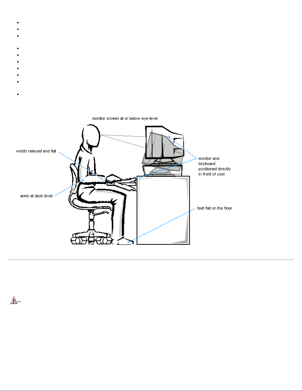
(from Dell and other sources) to help you correctly position your keyboard.
Set the monitor at a comfortable viewing distance (usually 510 to 610 millimeters [20 to 24 inches] from your eyes).
Make sure the monitor screen is at eye level or slightly lower when you are sitting in front of the monitor.
Adjust the tilt of the monitor, its contrast and brightness settings, and the lighting around you (such as overhead lights, desk
lamps, and the curtains or blinds on nearby windows) to minimize reflections and glare on the monitor screen.
Use a chair that provides good lower back support.
Keep your forearms horizontal with your wrists in a neutral, comfortable position while using the keyboard or mouse.
Always leave space to rest your hands while using the keyboard or mouse.
Let your upper arms hang naturally at your sides.
Sit erect, with your feet resting on the floor and your thighs level.
When sitting, make sure the weight of your legs is on your feet and not on the front of your chair seat. Adjust your chair’s
height or use a footrest, if necessary, to maintain proper posture.
Vary your work activities. Try to organize your work so that you do not have to type for extended periods of time. When you
stop typing, try to do things that use both hands.
When Working Inside Your Computer
Before you remove the computer cover, perform the following steps in the sequence indicated.
CAUTION: Do not attempt to service the computer system yourself, except as explained in this guide and
elsewhere in Dell documentation. Always follow installation and service instructions closely.
To help avoid possible damage to the system board, wait 5 seconds after turning off the system before removing a component
from the system board or disconnecting a peripheral device from the computer.
1. Turn off your computer and any peripherals.
2. Disconnect your computer and peripherals from their power sources. Also, disconnect any telephone or telecommunication
lines from the
computer.
Doing so reduces the potential for personal injury or shock.
Page 4
3. Touch
an unpainted metal surface on the chassis, such as the metal around the card-slot openings at the back of the
computer, before touching anything inside your computer.
In addition, take note of these safety guidelines when appropriate:
There is a danger of a new battery exploding if it is incorrectly installed. Replace the battery only with the same or
equivalent type recommended by the manufacturer. Discard used batteries according to the manufacturer’s
instructions.
While you work, periodically touch an unpainted metal surface on the computer chassis to dissipate any static
electricity that might harm internal components.
When you disconnect a cable, pull on its connector or on its strain -relief loop, not on the cable itself. Some cables have a
connector with locking tabs; if you are disconnecting this type of cable, press in on the locking tabs before disconnecting the
cable. As you pull connectors apart, keep them evenly aligned to avoid bending any connector pins. Also, before you
connect a cable, make sure both connectors are correctly oriented and aligned.
Handle components and cards with care. Don’t touch the components or contacts on a card. Hold a card by its edges or by
its metal mounting bracket. Hold a component such as a microprocessor chip by its edges, not by its pins.
WARNING
Protecting Against Electrostatic Discharge
Static electricity can harm delicate components inside your computer. To prevent static damage, discharge static electricity from
your body before you touch any of your computer’s electronic components, such as the microprocessor. You can do so by touching
an unpainted metal surface on the computer chassis.
As you continue to work inside the computer, periodically touch an unpainted metal surface to remove any static charge your body
may have accumulated.
You can also take the following steps to prevent damage from electrostatic discharge (ESD):
When unpacking a static- sensitive component from its shipping carton, do not remove the component from the antistatic
packing material until you are ready to install the component in your computer. Just before unwrapping the antistatic
packaging, be sure to discharge static electricity from your body.
When transporting a sensitive component, first place it in an antistatic container or packaging.
Handle all sensitive components in a static-safe area. If possible, use antistatic floor pads and workbench pads.
The following caution may appear throughout this document to remind you of these precautions:
CAUTION: See " Protecting Against Electrostatic Discharge".
Page 5

Introduction: Dell™ Precision™ WorkStation 610 Mini Tower
Systems
Overview System Features Important Note to Windows NT 4.0 Users Front Panel Back Panel Getting Help
Overview
Dell Precision 610 systems are high -speed, upgradable workstations designed around Intel® Pentium® II Xeon® processors.
These Dell systems support the high- performance Peripheral Component Interconnect (PCI) bus and the accelerated graphics port
(AGP) bus. Each system also has an Industry-Standard Architecture (ISA) design with one ISA slot that allows you to configure the
computer system to your initial requirements and then upgrade it as necessary.
This chapter describes the major hardware and software features of the system and provides information you will need to reinstall
the operating system, if necessary. It also provides information about the indicators and controls on the computer's front panel and
discusses connecting external devices to the computer.
System Features
The system offers the following features:
An Intel Pentium II Xeon processor. The following processor option is available:
- Single or dual Intel Pentium II Xeon processor(s) with an internal speed of 400 MHz or 450 MHz and an external speed of
100 MHz
The Intel Pentium II Xeon processor includes MMX technology designed to handle complex multimedia and communications
software. This processor incorporates new instructions and data types as well as a technique called single instruction,
multiple data (SIMD). SIMD allows the processor to process multiple data elements in parallel, thereby improving system
performance when you are running application programs written to take advantage of MMX technology.
The Intel Pentium II Xeon processor has a 16 -kilobyte (KB) internal data cache and a 16 -KB internal instruction cache, an
internal math coprocessor, and other advanced internal logic.
A secondary cache of 512 KB or 1 megabyte (MB) of static random-access memory (SRAM) integrated in the Slot 2 singleedge contact (Slot 2 SEC) cartridge. The secondary cache also provides error checking and correction (ECC) capability.
Dual- processor capability. The system allows the installation of a second Slot 2 SEC cartridge (operating at the same
frequency as the installed processor), which can be purchased as a kit from Dell. Dual processing improves performance
under operating systems that support multiprocessing, such as Microsoft
Windows NT
A 16-bit, integrated Plug and Play Crystal CS4237B audio controller that is Sound Blaster Pro-compatible and that supports
the Microsoft Windows
System memory that can be increased incrementally up to 512 MB using unbuffered synchronous dynamic random-access
memory (SDRAM) dual in-line memory modules (DIMMs), or up to 2048 MB using registered SDRAM DIMMS.
The memory subsystem also provides ECC capability, which corrects all single-bit memory errors and detects all multibit
errors. See "Adding Memory
®
4.0.
®
Sound System. See "Using the Integrated Audio Controller" for details.
". for details on installing additional memory.
®
Self- Monitoring Analysis and Reporting Technology (SMART) support, which warns you at system start- up if the hard-disk
drive has become unreliable. To take advantage of this technology, you must have a SMART- compliant hard-disk drive in
the computer. All enhanced integrated drive electronics (EIDE) and small computer system interface (SCSI) hard -disk drives
shipped with Dell Precision 610 systems are SMART -compliant.
The system's basic input/output system (BIOS), which resides in flash memory and can be upgraded remotely or by diskette
if required.
Plug and Play capability, which greatly simplifies the installation of expansion cards. Plug and Play support included in the
Page 6

system BIOS allows you to install a Plug and Play expansion card without setting jumpers or switches or performing other
configuration tasks. The ISA Configuration Utility (ICU) allows you to configure an existing ISA expansion card for conflictfree operation. Also, because the system BIOS is stored in flash memory, it can be updated to support future enhancements
to the Plug and Play standard.
NOTE: The Windows NT operating system does not provide ISA Plug and Play support. Therefore, some ISA
Plug and Play cards (such as modem, sound, and network cards) may not work with your Windows NT operating
system unless you configure them manually.
Wakeup On LAN capability, which, when enabled in the System Setup program, allows the system to be started up from a
server management console. Wakeup On LAN capability also allows remote computer setup, BIOS upgrades, software
downloading and installation, file updates, and asset tracking after hours and on weekends when local area network (LAN)
traffic is at a minimum.
Universal Serial Bus (USB) capability, which simplifies connection of peripheral devices such as mice, printers, and computer
speakers. The USB connectors on the computer's back panel provide a single connection point for multiple USB- compliant
devices. USB- compliant devices can also be connected and disconnected while the system is running.
CAUTION: Do not attach a USB device or a combination of USB devices that draw a maximum current over
500 milliamperes (mA) per channel or +5 volts (V). Attaching devices that exceed this threshold may cause
the USB ports to shut down. See the documentation that accompanied the USB devices for their maximum
current ratings.
A modular computer chassis with a minimum number of screws for easy disassembly and improved serviceability.
A high-speed, high -resolution AGP or PCI graphics adapter. (Documentation from the graphics adapter manufacturer is
included with the system.) AGP greatly improves graphics performance by providing a dedicated bus for a faster interface
between the video subsystem and system memory. AGP also allows conventional memory to be used for video-related
tasks.
The system board includes the following integrated features:
Five 32 - bit PCI expansion slots, including one that is a shared PCI (32-bit) /ISA (16 -bit) expansion slot and one that
has an extension for a redundant array of inexpensive disks (RAID) upgrade.
One AGP expansion slot.
A diskette drive interface, which supports a 3.5 - inch slimline diskette drive.
Two ATA -33 channels that support up to four EIDE devices. The primary and secondary channels utilize the PCI bus
to provide faster data throughput. Each channel supports extremely high -capacity EIDE drives, as well as devices
such as EIDE CD-ROM drives and EIDE tape drives.
SCSI support using two integrated SCSI channels.
- The primary channel provides Ultra2/Wide low voltage differential (LVD) (80-MB/second) support for highperformance SCSI hard-disk drives and an optional RAID subsystem.
- The secondary channel provides support for external Ultra/Wide
(40-MB/second) SCSI devices such as scanners and for internal narrow SCSI devices such as CD -ROM drives, tape
drives, and optical drives.
Two high-performance serial ports and one bidirectional parallel port for connecting external devices.
A Personal System/2 (PS/2)-style keyboard port and a PS/2-compatible mouse port.
An integrated 10/100- megabit-per-second (Mbps) 3Com ® PCI 3C905b-TX Ethernet network interface controller (NIC)
with Wakeup On LAN support. The NIC is configured using software described in "Using the Network Interface
Controller".
The following software is included with your Dell computer system:
Utilities that safeguard the system and enhance the operation of its hardware features; for example, the
AutoShutdown service lets you perform an orderly shutdown with a single touch of the power button. For more
information on these utilities, see "Using the Software Support Utilities
Video drivers for the Microsoft Windows NT 4.0 operating system.
NOTE: Some graphics adapters support the Windows NT 4.0 operating system only. Refer to the
documentation that came with your graphics adapter for more information.
".
To change the resolution, check the documentation that came with your monitor to determine the resolutions and
refresh rates supported by the monitor. Then check the documentation that came with your AGP or PCI graphics
adapter for instructions on changing the resolution.
Page 7

The System Setup program for quickly viewing and changing the system configuration information. For more
information on this program, see "Using the System Setup Program".
Enhanced security features available through the System Setup program (a setup password, a system password, a
system password lock option, a write- protect option for diskette drives, and automatic display of the system's service
tag number). In addition, a customer- definable asset tag number can be assigned via a software support utility and
viewed on the System Setup screens. A built- in chassis intrusion detector is also available. For more information, see
"Using the Software Support Utilities
Advanced power management options that can reduce the energy consumption of the system. For more information,
see "Using the System Setup Program
The ICU, which allows you to configure ISA expansion cards manually. After resources have been assigned to these
cards, the system BIOS can assign resources to PCI and Plug and Play expansion cards for a conflict- free
configuration. For more information, see " Using the ISA Configuration Utility
Dell Diagnostics for evaluating the computer's components and devices. For information on using the diagnostics, see
"Running the Dell Diagnostics" in the Diagnostics and Troubleshooting Guide .
Network device drivers for several network operating systems. These drivers are described in " Using the Network
Interface Controller ".
Desktop Management Interface (DMI) support for managing the computer system. DMI defines the software,
interfaces, and data files that enable the system to determine and report information about system components.
If the system has a Dell- installed Microsoft Windows or Microsoft Windows NT operating system, DMI is already
installed on the system's hard-disk drive. To learn more about DMI, double-click the Dell DMI Help icon in the Dell
DMI folder under the Start button.
Advanced Configuration and Power Interface (ACPI) for operating systems that support ACPI functionality.
The Dell OpenManage Client Administrator/Client program, which is available in administrator and client versions.
" and " Using the System Setup Program".
".
".
Dell OpenManage™ Client Administrator is the Dell software-management application interface for DMI. Dell
OpenManage Administrator is designed for network administrators to remotely manage connected Dell Precision 610
systems in a Dell DMI client network.
Features of Dell OpenManage Client Administrator include:
- Compliance with the DMI 2.0 specification
- Support for the Microsoft Windows NT 4.0 operating system
- Remote Flash BIOS support that enables you to perform BIOS updates on remote systems in a Dell DMI client
network
- Wakeup On LAN support that allows you to remotely turn on Dell systems with Wakeup On LAN capabilities in a
Dell DMI client network
- Password security that allows you to maintain standard attribute values and hardware configuration settings for the
local and remote systems in a Dell DMI client network
- A System Properties window that allows you to view, set, and disable certain hardware configuration settings for the
local and remote systems in a Dell DMI client network
- An Alert Settings window that enables you to monitor remote systems, set thresholds, and detect events for the local
system or remote system in a Dell DMI client network
- Support for the Microsoft Systems Management Server (SMS), which allows you to export one or more groups to an
SMS directory that the SMS administrator can access
- Automated mapping of one or more groups to a user- defined directory
- A LAN Adapter component that lists information about the NIC for the local or remote system
- A Dell event log that stores events generated by Dell systems
- Automated inventory control for all active discovered systems
- Support for the application used to create user-definable attributes (UDAs)
Page 8

Dell OpenManage Client is the Dell software-management application interface for DMI. Dell OpenManage Client is
designed for local systems in a Dell DMI client network and includes the following features:
Windows NT 4.0 Microsoft updated ATAPI driver – See "Microsoft Updated ATAPI Drivers".
- Compliance with the DMI 2.0 specification
Support for the Microsoft Windows NT 4.0 operating system
- Support to view and modify a local system's hardware configuration settings
- Support for the Microsoft SMS, which allows you to export one or more groups to an SMS directory that the SMS
administrator can access
- Automated mapping of one or more groups to a user- defined directory
- A LAN Adapter component that lists detailed information about the NIC for the local system
- An event log that stores events generated by the system
- Support for the application used to create UDAs
If you ordered Dell -installed software, such as the Microsoft Windows NT operating system, Dell provides a menu that allows
you to make program diskette sets of the Dell-installed software. A program diskette set is an uninstalled version of a
software package that you can use to reinstall or reconfigure the software. You can use this same menu to remove diskette
image files (individual files that correspond to each diskette in a program diskette set) to reclaim space on the computer's
hard - disk drive. For more information on making program diskette sets, see the online help provided in the Program Diskette
Maker, which is available in the Dell Accessories program folder.
Important Note to Windows NT 4.0 Users
Your system was configured by Dell to optimize the features of your computer and of the Microsoft Windows NT 4.0
operating system. If you need to reinstall this operating system, there are several supplemental items that also must be
installed to return the system to its full functionality. See the appropriate subsection that follows for your operating system.
Reinstalling Windows NT 4.0
To reinstall the Windows NT 4.0 operating system, you must have the following items:
Windows NT 4.0 CD from Dell
Windows NT 4.0 SCSI controller driver diskettes
Windows NT 4.0 Service Pack 3 CD
Windows NT 4.0 Microsoft updated ATAPI driver diskette
Windows NT 4.0 video driver diskettes
Windows NT 4.0 NIC driver diskette
Windows NT 4.0 audio driver diskette
NOTE: You must create all the diskettes listed previously by using the Program Diskette Maker, which is located
in the Dell Accessories folder.
CAUTION: When reinstalling Windows NT 4.0, you must exit the installation process by pressing <F6> when
the system displays the message Setup is inspecting your hardware configuration. Then you must install
the SCSI controller drivers as described in "Using the Integrated SCSI Controllers
installing the other supplemental items. If you do not interrupt the installation procedure, the system will
misidentify the primary SCSI controller as being the same as the secondary SCSI controller and lock up.
" and then proceed with
NOTE: You must install Windows NT 4. 0 Service Pack 3 and the Microsoft updated ATAPI driver before
installing the NIC drivers. Otherwise, the integrated NIC will not function properly.
See the Dell Microsoft Windows NT Workstation 4.0 Setup Guide for general installation information for Windows NT 4.0
and for information about other drivers or supplements that may be required. For installation instructions for the various
drivers, see the appropriate section or document as follows:
Windows NT 4.0 SCSI controller drivers – See "SCSI Drivers for Windows NT 4.0"
Page 9
Windows NT 4.0 video drivers – See the documentation for your graphics adapter.
Windows NT 4.0 NIC driver – See "Windows NT 4.0 NIC Driver".
For information about enabling, disabling, or configuring input/output (I/O) ports and connectors, see "Using the System
Windows NT 4.0 audio drivers – See "Audio Drivers for Windows NT 4.0".
Creating Disk Partitions for Windows NT 4.0
After you have completed the setup procedure for the Dell-installed Microsoft Windows NT 4.0 operating system, you can
perform the following procedure to create disk partitions on your large-capacity hard-disk drive(s):
1. Click the Start button, point to Programs, and click Administrative Tools.
2. Click Disk Administrator.
Follow the instructions in the Disk Administrator utility to partition and format your drives.
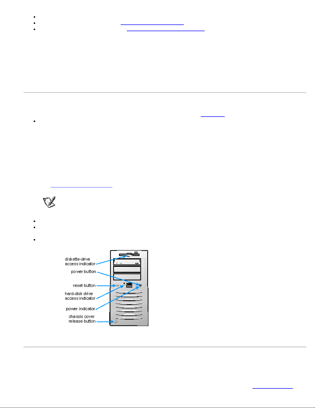
Front Panel
The computer's front panel contains the following indicators and controls (see Figure 1-1 ):
The power button provides control of the system's alternating current (AC) input power. The push- button switch
operates as follows:
- When the computer is turned off, pressing the button turns the computer on.
- When the computer is turned on, pressing the button turns the computer off. However, a low- voltage (standby)
current is maintained by the power supply. To completely remove all power from the system, unplug the AC power
cable from its source.
For systems running Microsoft Windows NT with the Dell AutoShutdown service operational, pressing the power
button causes the system to perform an orderly operating system shutdown before turning off. (For more information,
see "Dell AutoShutdown Service
NOTE: A Display Power Management Signaling (DPMS) monitor does not begin warming up until the
computer to which it is attached is turned on. Thus, some DPMS monitors may not display a video image
until several seconds after you turn on the computer.
The power indicator light is green during normal system operation and amber when the computer is in sleep mode.
The hard- disk drive access indicator lights up when a hard-disk drive is in use. (Drive access indicators for diskette
drives and tape drives are located on the front of the drives.)
The reset button reboots (restarts) the system without your having to turn the power off and then on again. Rebooting
the system in this manner reduces stress on system components.
".
Figure 1-1. Front Panel
Back Panel
The computer's back panel contains various ports and connectors for attaching external devices and includes a security
cable slot. These features are described in the following subsections.
Page 10
Setup Program". For detailed descriptions and illustrations of each port and connector on the back panel, see " I/O Ports
and Connectors".
Connecting External Devices
You can connect various external devices, such as a mouse and printer, to the I/O ports and connectors on the computer's
back panel. The system BIOS detects the presence of most external devices when you boot or reboot the system. When
connecting external devices to the computer, follow these guidelines:
Check the documentation that accompanied the device for specific installation and configuration instructions.
For example, most devices must be connected to a particular I/O port or connector to operate properly. Also, external
devices like a mouse or printer usually require you to load software files called device drivers into system memory
before they will work. These software drivers help the computer recognize the external device and direct its operation.
Dell recommends that you attach external devices only while the computer is turned off unless you are instructed
otherwise in the documentation for the particular device. Then turn the computer on before turning on any external
devices unless the documentation for the device specifies otherwise. (If the computer does not seem to recognize the
device, try turning on the device before turning on the computer.)
CAUTION: When disconnecting external devices from the back of the computer, wait 10 to 20 seconds after
disconnecting the computer from AC power before you disconnect the device to avoid possible damage to
the system board.
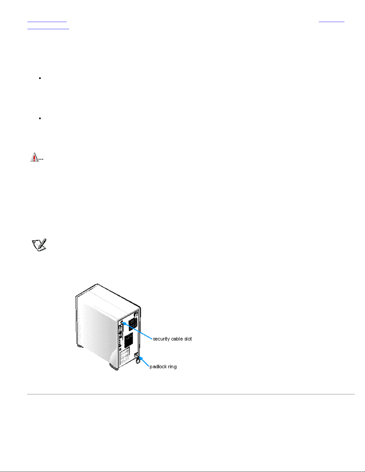
Security Cable Slot and Padlock Ring
On the back of the computer are a security cable slot and padlock ring (see Figure1-2) for attaching commercially available
antitheft devices. Security cables for personal computers usually include a segment of galvanized cable with an attached
locking device and key. To prevent unauthorized removal of the computer, loop the cable around an immovable object,
insert the locking device into the security cable slot on the back of the computer, and lock the device with the key provided.
Complete instructions for installing this kind of antitheft device are usually included with the device.
NOTE: Antitheft devices are of differing designs. Before purchasing such a device, make sure it will work with the
cable slot on the computer.
The padlock ring allows you to secure the computer cover to the chassis to prevent unauthorized access to the inside of the
computer. To use the padlock ring, insert a commercially available padlock through the ring and then lock the padlock.
Figure 1-2. Security Cable Slot and Padlock Ring
Getting Help
If at any time you don't understand a procedure described in this guide or if the system does not perform as expected, Dell
provides a number of tools to help you. For more information on these help tools, see the chapter titled "Getting Help" in
your Diagnostics and Troubleshooting Guide.
Page 11

Using the Software Support Utilities: Dell™ Precision™
WorkStation 610 Mini Tower Systems
Overview Dell-Installed Software
Support Utilities
Backing Up the
Software Support
Utilities
Software Support
Utilities on Diskette
System Utilities
and Services
Microsoft Updated
ATAPI Drivers
Overview
Your Dell system comes with software support utilities on diskette or on your computer's hard-disk drive. These software support
utilities include system utilities, system services, and Microsoft updated ATAPI drivers, all of which are documented in this chapter.
For information on the additional software support utilities you received with your system, refer to the following chapters or
documents:
Video drivers - See the documentation from the graphic adapter manufacturer. (Video drivers support the video graphics
requirements of a variety of monitors and application programs running under the Microsoft Windows NT 4.0 operating
system.)
NOTE: Some graphic adapters support the Windows NT 4.0 operating system only. Refer to the documentation
that came with your graphic adapter for more information.
Audio drivers - See "Using the Integrated Audio Controller".
Network interface drivers - See "Using the Network Interface Controller ".
SCSI interface drivers - See "Using the Integrated SCSI Controllers".
System utilities and services can be used to safeguard your system and to explicitly control certain hardware features. Refer to
"System Utilities and Services
" for information about these utilities.
Microsoft updated ATAPI drivers are provided with your Dell system for the Windows NT 4.0 operating system. Refer to "Microsoft
Updated ATAPI Drivers" for information about these drivers.
Dell-Installed Software Support Utilities
The system utilities, services, and Microsoft updated ATAPI drivers are already installed on your hard-disk drive in two different
forms: as working utilities, operative immediately, and as diskette images.
In case you later need to reinstall the files for any reason, you need to copy the diskette images to a backup diskette (see the next
section, Backing Up the Software Support Utilities). From the backup diskette, you can install the desired file(s) to a directory on
your hard-disk drive. Further instructions for installing the utilities, services, and drivers are provided later in this chapter.
Backing Up the Software Support Utilities
Dell recommends that you create original diskette copies, or program diskette sets, of your Dell- installed software. You will need
these diskettes if you ever want to reconfigure or reinstall your Dell-installed software. To create program diskettes, use the
Program Diskette Maker (available through the Dell Accessories program folder).
Software Support Utilities on Diskette
If you received Dell software support diskettes, the Dell system utilities, services, and Microsoft updated ATAPI drivers are provided
on these diskettes. To use a utility, service, or Microsoft updated ATAPI driver, you must install the utility, service, or driver as
described later in this chapter.
NOTE:
On each software support diskette set you receive, a release.txt file may be included (on diskette 1 of the set).
Page 12

If included, the release.txt file contains the latest updates to the information in this guide. Use the editor included with
your operating system to view and/or print the contents of the release.txt file.
System Utilities and Services
The following utilities and services are included on your Dell system utilities diskette:
The Asset Tag utility lets you enter a system asset tag number into nonvolatile random -access memory (NVRAM).
Thereafter, you can display this number using the Asset Tag utility or the System Setup program.
The Dell AutoShutdown service provides Windows NT 4.0 the ability to perform an orderly system shutdown when the
power button is pressed.
The Dell ThermalShutdown service provides Windows NT 4.0 the ability to perform an orderly system shutdown in the event
of a thermal failure. This feature prevents permanent damage to your system caused by a component overheating.
The Auto Power On utility (which runs under the MS- DOS ® operating system only) reports what caused the system to
power on, such as the power switch or a call from the Auto Power On utility itself. This utility also enables you to create a
batch file to carry out a series of commands when your system is powered on by the Auto Power On feature or by the
power switch.
Reinstalling the Dell System Utilities and Services for Windows NT 4.0
The system utilities and services are already installed and operative on your hard-disk drive. If, for any reason, you need to reinstall
the utilities and services, perform the following steps:
1. If you have not already done so, use the Program Diskette Maker to make a diskette copy of the Dell system utilities diskette
image on your hard-disk drive.
The Program Diskette Maker is available through the Dell Accessories program folder. For more information, refer to the
online help provided in the Program Diskette Maker.
2. Start Windows NT and log in as Administrator or as a user with administrative privileges. If you are already running Windows
NT, close any open documents or application programs.
3. With the backup diskette in drive A, run the setup.exe program from the diskette.
4. Follow the on- screen instructions to install the Dell utilities and/or services. When the installation is finished, restart your
system to activate the services.
5. Verify that the utilities and/or service(s) are installed and running.
Double-click the Services icon in the Control Panel. AutoShutdown and ThermalShutdown should be listed with the status of
Started.
The Asset Tag utility and Auto Power On utility (if installed) are located in the c:\dellutil directory on the drive containing the
Windows NT 4.0 system files.
Removing a Service
To remove a service, perform the following steps:
1. Insert the backup diskette in drive A.
2. Run remove.exe from the diskette.
3. Select the service(s) you want to remove and click Next.
Asset Tag Utility
The Asset Tag utility allows you to enter an asset tag number for the computer. The default System Setup screens (see Figure 3-
1) do not show the asset tag number unless you enter one using this utility.
NOTE: The Asset Tag utility does not function correctly under Windows NT. However, you may be able to run the utility
in Windows NT by booting from a DOS diskette or diagnostics diskette, exiting to the DOS prompt, and then entering the
asset command on the DOS command line.
Page 13

You can use the Asset Tag utility to enter an asset tag number that you or your company assign to the computer; you can also use
it to reenter the computer's service tag number if that becomes necessary.
Use the asset command from an MS-DOS prompt. To view existing asset tag and service tag numbers, type asset and press
<Enter>. (You can also view the asset tag number by using the System Setup program described in Chapter 3.) To display the
Asset Tag utility help screen, type asset /? and press <Enter>.
Assigning and Deleting an Asset Tag Number
An asset tag number can have up to ten characters; any combination of characters excluding spaces is valid. To assign or change
an asset tag number, type asset and a space followed by the new number; then press < Enter>. For example, type the following
command line and press <Enter>:
asset 1234$ABCD&
When prompted to verify the asset tag number, type y and press <Enter>. The system then displays the new or modified asset tag
number and the service tag number.
To delete the asset tag number without assigning a new one, type asset /d and press <Enter>.
Assigning and Deleting an Owner Tag
You can use the Asset Tag Utility to assign an owner tag that will be displayed on the Dell logo screen whenever you boot your
system.
An owner tag can be up to 80 characters; any combination of letters, numbers, and spaces is valid. To assign an owner tag, type
asset /o and a space followed by the new owner tag; then press <Enter>. For example, type the following command line and press
<Enter>:
asset /o ABC Company
When prompted to verify the owner tag, type y and press <Enter>. The system then displays the new owner tag.
To delete the owner tag without assigning a new one, type asset /o /d and press <Enter>.
Dell AutoShutdown Service
The Dell AutoShutdown service (available with the Windows NT 4.0 operating systems) provides the ability to perform an orderly
system shutdown when the power button is pressed.
How AutoShutdown Works
The power button operates in two modes: immediate and AutoShutdown mode.
When the system is off, the power button always acts in immediate mode- that is, when the button is pressed, the system starts up
immediately.
When the system is on and the AutoShutdown service is installed, the power button operates in AutoShutdown mode. Pressing the
power button signals the service to perform an orderly operating system shutdown (reducing the possibility of data loss and file
corruption) before removing power from the system. During the shutdown sequence, the power indicator on the front panel of the
computer flashes.
NOTE: The presence of the AutoShutdown service does not affect the operation of the system reset button.
If Your Operating System Locks Up
If, when you press the power button, the power indicator begins to flash but the system does not turn off, your operating system
may have locked up. (A locked -up operating system cannot perform a safe shutdown.)
To ensure that the system can be turned off under these circumstances, a manual intervention mechanism has been included in
Page 14

the software. To turn off a locked- up system, either press the power button a second time or press the reset button.
Dell ThermalShutdown Service
The Dell ThermalShutdown service helps protect components such as the system processor and the primary hard-disk drive from
damage due to overheating. It can also protect your system data from loss or corruption resulting from a thermal-related system
shutdown.
When installed, the service uses sensors to monitor the temperature of critical internal components. If a sensor detects a thermal
event, the system first performs an orderly operating system shutdown and then turns itself off. During the shutdown phase, the
power indicator flashes and a screen message notifies the user that the system is shutting down.
If the ThermalShutdown service is unable to shut down the system, the system will be shut down if Thermal Power-off is enabled
in the System Setup program. (See "Thermal Power-Off
CAUTION: The thermal sensors are always installed and operational. If the ThermalShutdown service is not
installed and a thermal event occurs, the system turns off after approximately 3 minutes if Thermal Power-off is
enabled in the System Setup program.
Auto Power On Utility
The Auto Power On utility (available for MS-DOS only) enables your system to automatically perform routine tasks in your absence.
For example, you might want your system to turn on at night and perform a backup procedure. To use the utility, you need to
create a batch file containing the command(s) or program(s) that you want performed in your absence. The Auto Power On utility
determines whether system power was turned on by the power button or by the Auto Power On setting in the System Setup
program and passes this information on to your batch file, which initiates the appropriate commands at system start-up. See "Auto
Power On" in for information on setting Auto Power On in the System Setup program.
" in for more information.)
The following example shows the contents of a possible batch file.
NOTE: The first three lines of your batch file must match the first three lines in the following example.
autopowr
if errorlevel 2 goto alarm
if errorlevel 1 goto button
:alarm
call alarm.bat
autopowr /off
:button
call button.bat
goto end
The autopowr /off command turns off your computer.
Installing the Auto Power On Utility
The Auto Power On utility is already installed on your hard-disk drive. If you need to reinstall the Auto Power On utility, perform the
following steps:
1. If you have not already done so, use the Program Diskette Maker to make a diskette copy of the Dell System Utilities
diskette image on your hard-disk drive.>
The Program Diskette Maker is available through the Dell Accessories program folder. For more information, refer to the
online help provided in the Program Diskette Maker.
2. With the backup diskette in drive A, copy autopowr.com from the diskette to a directory of your choice on your hard-disk
drive.
If the path statement in your autoexec.bat file does not already contain the directory in which you reinstalled the Auto Power On
Page 15

utility, modify the path statement to include that directory. (See your MS -DOS reference documentation for information on
modifying the autoexec.bat file.)
Microsoft Updated ATAPI Drivers
Microsoft updated ATAPI drivers (provided for Windows NT 4.0 operating system) offer a performance improvement by off -loading
certain functions from the system processor during multithreaded operations. Dell has installed the Microsoft updated ATAPI driver
for your operating system, and it is operative when you receive your computer. No further installation or configuration is needed.
NOTE: If Windows NT 4.0 is reinstalled, the Microsoft updated ATAPI drivers must also be reinstalled.
The driver for Windows NT 4.0 has also been copied to your hard- disk drive in diskette-image form. If you need to reinstall or
remove this driver, you can do so as described in the following subsections.
Reinstalling the Windows NT 4.0 Microsoft Updated ATAPI Driver
NOTE: To install the Microsoft updated ATAPI driver for Windows NT 4.0, you must have a mouse connected to the
system and Windows NT 4.0 must already be installed on the hard -disk drive connected to the primary EIDE channel.
To reinstall the Microsoft updated ATAPI driver for Windows NT 4.0, perform the following steps:
1. If you have not already done so, use the Program Diskette Maker to make a diskette copy of the Dell Microsoft updated
ATAPI driver diskette image on your hard-disk drive.
The Program Diskette Maker is available through the Dell Accessories program folder. For more information, refer to the
online help provided in the Program Diskette Maker.
2. Start the Windows NT operating system. If you are already running Windows NT, close any open documents or application
programs.
3. Insert the Microsoft updated ATAPI driver diskette in drive A.
4. Click the Start button.
5. Click Run, type a:\setup.bat in the Run window, and then click OK.
A black screen will quickly appear and disappear, which indicates that the driver file has been loaded. Setup automatically
saves the existing atapi. sys driver as atapi.000 and loads the new driver into the system32\drivers subdirectory in the
Windows NT directory.
6. Remove the diskette from drive A. Then restart the computer.
NOTE: To enable or disable direct memory access (DMA) while using the Microsoft updated ATAPI driver, run
dmacheck.exe from \support\utils\i386 on the Microsoft Windows NT Service Pack 3 CD-ROM.
CAUTION: If your system contains an Iomega Zip drive, do not enable DMA for the updated ATAPI driver for
Windows NT 4.0. Doing so will result in loss of data on your system.
Removing the Windows NT 4.0 Microsoft Updated ATAPI Driver
To remove the Microsoft updated ATAPI driver, follow these steps:
1. Start the Windows NT operating system. If you are already running Windows NT, close any open documents or application
programs.
2. Use Explorer to open the system32\drivers subdirectory in the Windows NT directory.
3. Rename the existing atapi.sys file to atapi.bak.
4. Rename the atapi.000 file to atapi.sys.
5. Restart the computer.
Page 16

Using the System Setup Program: Dell™ Precision™ WorkStation
610 Mini Tower Systems
Overview Entering the System
Setup Program
Using the System
Password Feature
Using the Setup Password
Feature
System Setup Screen Using the System Setup
Program
Disabling a Forgotten
Password
Responding to Error
Messages
System Setup
Options
Overview
Each time you turn on your computer system or press the reset button, the system compares the hardware installed in the system
to the hardware listed in the system configuration information stored in nonvolatile random-access memory (NVRAM) on the
system board. If the system detects a discrepancy, it generates error messages that identify the incorrect configuration settings.
The system then prompts you to enter the System Setup program to correct the setting.
You can use the System Setup program as follows:
To change the system configuration information after you add, change, or remove any hardware in your system
To set or change user-selectable options - for example, the time or date on your system
To enable or disable all integrated devices in your system
You can view the current settings at any time. When you change a setting, in many cases, you must reboot the system before the
change takes effect.
After you set up your system, run the System Setup program to familiarize yourself with your system configuration information and
optional settings. For future reference, Dell recommends that you print the System Setup screen (by pressing the <Print Screen>
key) if you have a local printer installed, or write down the information if you do not have a printer.
Before you use the System Setup program, you need to know the kind of diskette drive(s) and hard-disk drive(s) installed in your
computer. If you are unsure of any of this information, see the Manufacturing Test Report that was shipped with your system and is
located in the Dell Accessories folder.
Entering the System Setup Program
Enter the System Setup program as follows:
1. Turn on your system.
If your system is already on, shut it down and then turn it on again.
2. When the Press <F2> to Enter Setup window appears in the upper-right corner of the screen, press <F2>.
If you wait too long and your operating system begins to load into memory, let the system complete the load operation ; then shut
down the system and try again.
NOTE: To ensure an orderly system shutdown, consult the documentation that accompanied your operating system.
You can also enter the System Setup program by responding to certain error messages. See "Responding to Error Messages".
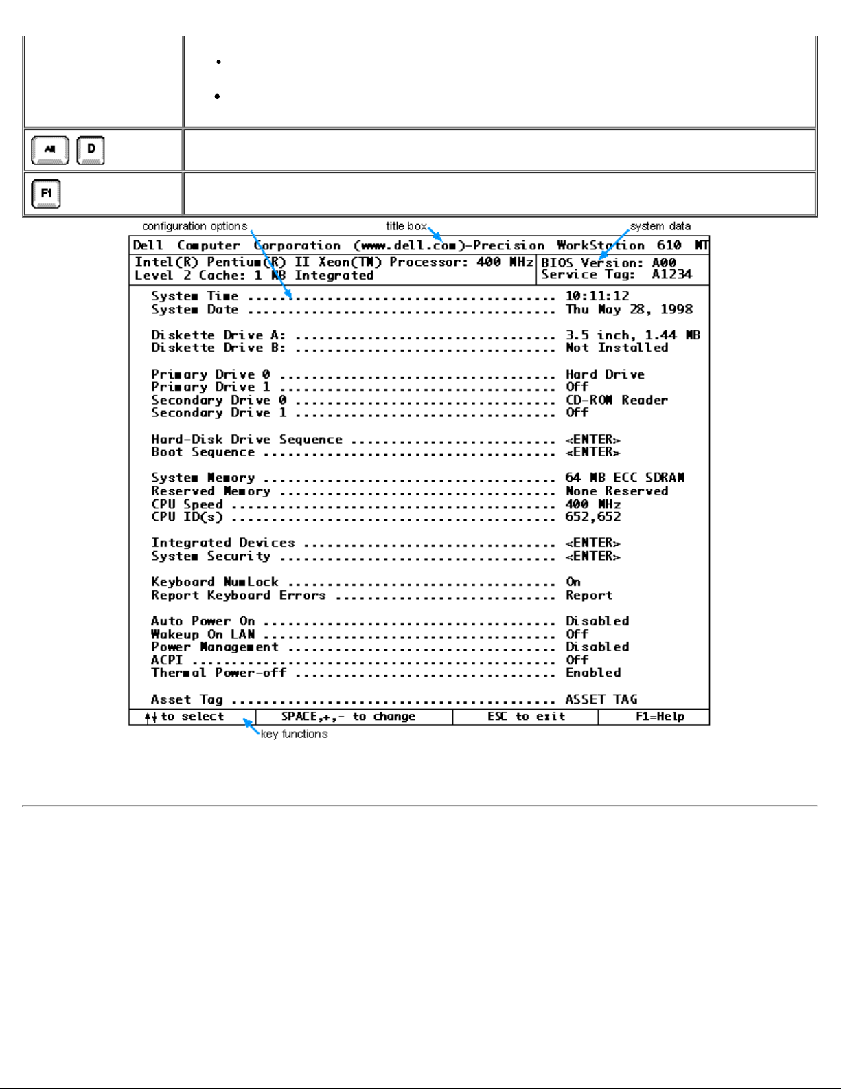
System Setup Screen
Page 17
The System Setup screen displays the current setup and configuration information and optional settings for your system. (Typical
Save Changes and Exit option exits the System Setup program and reboots the system,
examples are illustrated in Figure 3-1.) Information on the System Setup screen is organized in four areas:
Title box
The box at the top of the screen lists the system name.
System data
The two boxes below the title box display information about your system, such as the basic input/output system (BIOS)
revision number.
Configuration options
The box under the system data boxes lists options that define the installed hardware in your computer.
Fields beside the options contain settings or values; you can change those that appear in white on the screen. You cannot
change settings or values that appear in a color highlight because they are determined by the system.
Some options have multiple fields, which may show settings or values as bright or less bright depending upon the settings or
values you entered in other fields.
Key functions
The line of boxes across the bottom of the screen lists keys and their functions within the System Setup program.
Using the System Setup Program
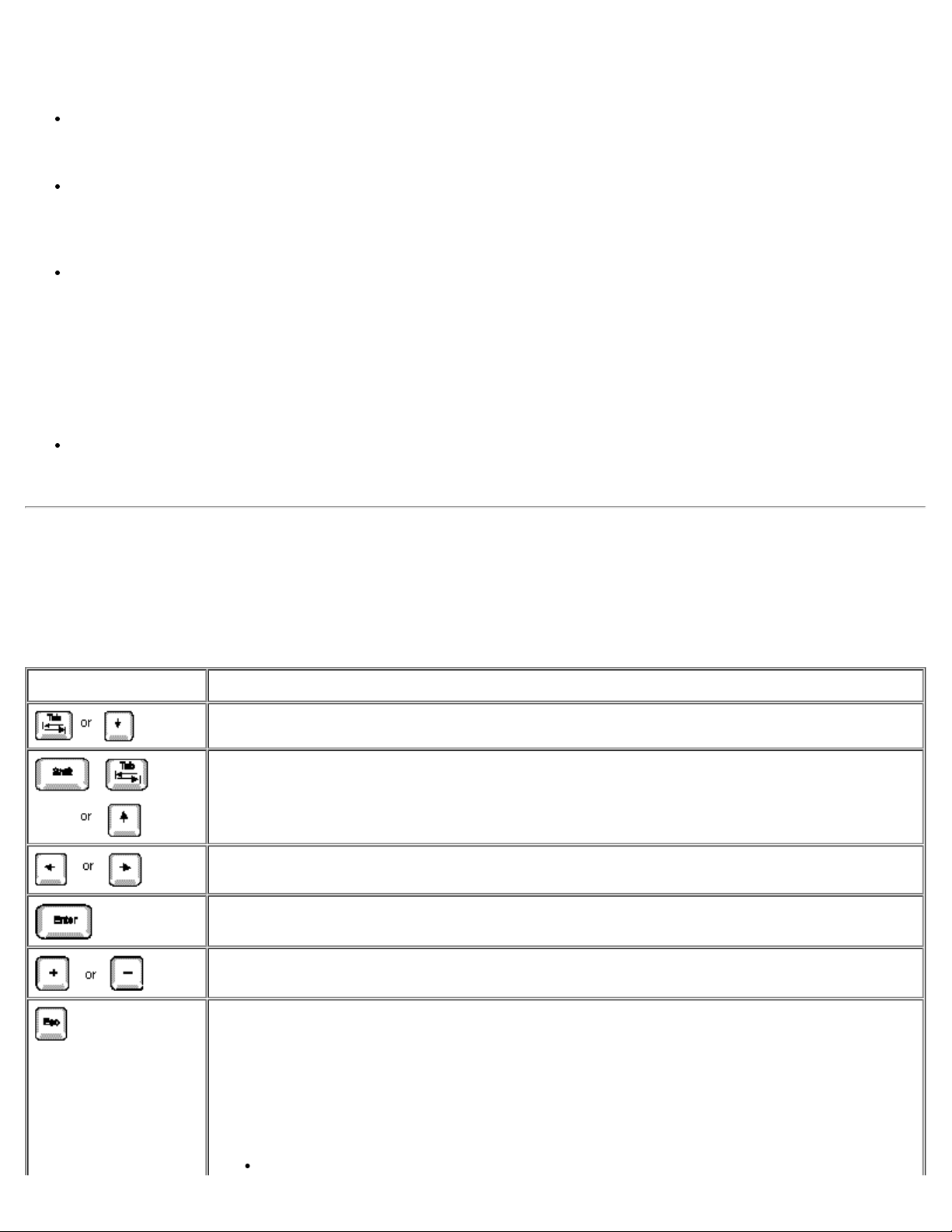
Table 3 -1 lists the keys you use to view or change information on the System Setup screen and to exit the program.
Table 3-1. System-Setup Navigation Keys
Keys Action
Moves to the next field.
Moves to the previous field.
Cycles through the settings in a field. In many fields, you can also type the appropriate value.
Enters the selected field's pop-up settings menu.
Cycles through the settings in the selected field's pop- up settings menu.
Saves the selected settings in a field's pop -up settings menu and returns to the main System Setup
screen. For a few options (as noted in the help area) the changes take effect immediately.
Exits the System Setup program at the System Setup screen if no settings in any option were
changed. Provides exit menu options if changes were made. Highlight a menu option to select it and
press <Enter> to activate it.
Page 18
implementing any changes you have made.
Discard Changes and Exit option exits the System Setup program without rebooting the system
and returns the system to its previous state - the boot routine.
Return to Setup option returns to the System Setup screen.
Resets the selected options to their default settings.
Displays help information for the selected option.
Figure 3 -1. Typical System Setup Screen
System Setup Options
The following subsections explain in detail each of the options on the System Setup screen.
System Time
System Time resets the time on the computer's internal clock.
Time is kept in a 24-hour format (hours:minutes:seconds). To change the time, press the left- or right- arrow keys to select a field,
and then press <+> or < -> to increase or decrease the number. If you prefer, you can type numbers in each of the fields.
Page 19

System Date
System Date resets the date on the computer's internal calendar.
Your system automatically displays the day of the week corresponding to the settings in the month, day-of-month, and year fields.
To change the date, press the left- or right-arrow keys to select a field, and then press <+> or < -> to increase or decrease the
number. If you prefer, you can type numbers in the day-of-month and year fields.
Diskette Drive A and Diskette Drive B
Diskette Drive A and Diskette Drive B identify the type(s) of diskette drive(s) installed in your computer. The standard configuration
for this system is one 3.5 -inch slimline diskette drive installed at the top of the drive cage. This drive is designated Diskette Drive A
and is normally the only diskette drive in the computer.
The options always match the physical locations of the drives in your computer - the first drive listed is the top drive in your
computer.
The Diskette Drive A and Diskette Drive B options have the following settings:
5.25 Inch, 360 KB
5.25 Inch, 1.2 MB
3.5 Inch, 720 KB
3.5 Inch, 1.44 MB
Not Installed
NOTE: Tape drives are not reflected in the Diskette Drive A and Diskette Drive B settings. For example, if you have a
single diskette drive and a tape drive attached to the diskette/tape drive interface cable, set Diskette Drive A to match
the characteristics of the diskette drive and set Diskette Drive B to Not Installed.
Primary Drive and Secondary Drive
Primary Drive identifies drives attached to the primary enhanced integrated drive electronics (EIDE) interface connector (labeled
"IDE1") on the system board; Secondary Drive identifies drives connected to the secondary EIDE interface connector (labeled
"IDE2"). Dell recommends that you use the secondary EIDE interface connector for EIDE CD-ROM and EIDE tape drives.
NOTE: For all devices obtained from Dell that use the built- in EIDE controller, set the appropriate Drive option to Auto.
The four Primary Drives n and Secondary options identify the type of EIDE devices installed in the computer. For each drive, five
parameters can be chosen as a group by drive-type number, entered individually from the keyboard, or set automatically. A drive-
type number specifies the parameters of a hard-disk drive, based on a table recorded in the system's BIOS.
To choose a setting for each option, press <Enter> to access the field's pop- up settings menu. Then type characters from the
keyboard or use the left- or right- arrow key to cycle through the following settings:
Auto (use this setting for all EIDE devices from Dell)
Off
User 1 or User 2
A specific drive-type number
NOTE: Operating systems that bypass the system BIOS may not obtain optimum hard- disk drive performance.
EIDE Devices
Page 20

For EIDE hard-disk drives, the system provides an automatic drive-type detect feature. To use this feature for Primary Drive 0,
highlight the Primary Drive 0 option and type a (for automatic); to use it for Primary Drive 1, highlight the Primary Drive 1 option
and type a. In each case, the option setting changes to Auto. After the system reboots, the System Setup program automatically
sets the correct drive-type number and options for each drive.
Before installing a new EIDE hard-disk drive, also check the documentation that came with the drive to verify that all jumper
settings on the drive are appropriate for your configuration.
If You Have a Problem
If the system generates a drive error message the first time you boot your system after installing an EIDE drive, it may mean that
your particular drive does not work with the automatic drive-type detect feature. If you think that your problem is related to drive
type, try entering your drive-type information as described in the following subsections.
If You Know the Drive-Type Number
Use the drive -type number you found in the documentation that came with the drive, or if the drive was installed by Dell when you
purchased your system, access the Manufacturing Test Report from the Dell Accessories folder.
To set the drive-type number in the System Setup program, highlight the appropriate drive option (Primary Drive 0 or Primary
Drive 1) and type the correct drive -type number. If you prefer, you can press the right- or left-arrow key to increase or decrease,
respectively, the drive - type number until the correct one is displayed.
If You Do Not Know the Drive-Type Number
The Primary or Secondary Drive 0 and Drive 1 options display the following five parameters for each drive:
Drive Type is the drive-type number for the selected hard-disk drive.
Capacity (automatically calculated by the system) indicates the number of millions of bytes of storage provided by the drive.
Cylinders is the number of logical cylinders.
Heads indicates the number of logical heads in the drive.
Sectors is the number of logical sectors per track.
If none of the supported drive types match the parameters of your new drive, you can enter your own parameters. To do so,
highlight the Primary or Secondary Drive 0 option and type u to display User 1. You can then use the right- or left-arrow key to
switch between the User 1 and User 2 settings (only two user- defined drive types are allowed). Then press <Tab> to highlight
each of the parameter fields in succession, and enter the appropriate number for each field.
NOTE: The User 1 and User 2 drive types can be used for both the Primary and Secondary Drive 0 and Drive 1
options. However, if you select the User 1 or User 2 drive type, you may not obtain optimum hard-disk drive
performance. Also, the User 1 and User 2 drive types cannot be used for hard-disk drives greater than 528 megabytes
(MB) in capacity.
Hard-Disk Drive Sequence
Hard-Disk Drive Sequence lists installed adapter cards and devices in the order they will be initialized. The first hard-disk drive in
the list becomes the bootable drive C.
Boot Sequence
Boot Sequence enables you to set the order of the devices from which the system attempts to boot.
The term boot refers to the system's start-up procedure. When turned on, the system "bootstraps" itself into an operational state by
loading into memory a small program, which in turn loads the necessary operating system. Boot Sequence tells the system where
to look for the files that it needs to load.
Page 21

To set the boot device order, press <Enter> to access the field's pop- up options menu. Use the up- and down-arrow keys to move
effect immediately (rebooting the system is not required).
through the list of devices. Press the spacebar to enable or disable a device (enabled devices appear with a check mark). Press
<+> or < -> to move a selected device up and down the list. The following subsections detail typical choices.
Diskette Drive A:
Selecting Diskette Drive A: as the first device causes the system to boot from drive A first. If the system finds a diskette that is not
bootable in the drive or finds a problem with the drive itself, it displays an error message. If it does not find a diskette in the drive,
the system tries to boot from the next device in the boot sequence list.
Hard- Disk Drive C:
Selecting Hard Disk Drive C: causes the system to boot first from the hard - disk drive and then from the next device in the boot
sequence list.
IDE CD- ROM Reader
Selecting IDE CD -ROM Reader causes the system to boot from the CD-ROM drive first. If the system finds a CD that is not
bootable in the drive or finds a problem with the drive itself, it displays an error message. If it does not find a CD in the drive, the
system tries to boot from next device in the boot sequence list.
PXE
Selecting PXE (Preboot eXecution Environment) causes the system to boot from the integrated network interface controller (NIC)
first. If a boot routine is not available from the network server, the system tries to boot from the next device in the boot sequence
list.
System Memory
System Memory indicates the entire amount of installed memory detected in your system, except for memory on Expanded Memory
Specification (EMS) expansion cards. After adding memory, check this option to confirm that the new memory is installed correctly
and is recognized by the system.
Reserved Memory
Reserved Memory allows you to designate a region of system board memory that can be supplied by an expansion card. You
should not enable the reserved memory feature unless you are using an expansion card that requires special addressing.
For example, you may have a memory expansion card that needs to be addressed starting at 15 MB. Selecting the 15MB-16MB
setting in the Reserved Memory option specifies that the base memory from 15 MB to 16 MB comes from the memory expansion
card (the base memory below the 15- MB address comes from the dual in-line memory modules [DIMMs] on the system board).
The Reserved Memory option has the following settings:
None Reserved (the default)
512KB-640KB
15MB-16MB
CPU Speed
CPU Speed indicates the processor speed at which your system boots.
Press the left- or right - arrow key to toggle the CPU Speed option between the resident processor's rated speed (the default
setting) and a lower compatibility speed, which lets you accommodate speed-sensitive applications. A change to this option takes
Page 22

To toggle between the rated processor speed and the compatibility speed while the system is running in real mode, press
<Ctrl><Alt><\>. (For keyboards that do not use American English, press <Ctrl><Alt> <#>.)
CPU ID(s)
CPU ID(s) provides the manufacturer's identification code for the installed processor(s).
Integrated Devices
Integrated Devices configures the devices integrated into the system board. Press <Enter> to configure these options.
Sound
Sound determines whether the integrated audio controller is On (the default) or Off. When Sound is set to Off, no sounds are
emitted from any attached external speakers or from the on- board speaker, except for beep codes. Set Sound to Off if you want to
use a sound expansion card instead of the integrated audio controller or if you need the resources used by the controller.
NIC
Network Interface Controller (NIC) determines whether the integrated NIC is set to On, Off, or On with PXE. The default is On,
which means that the NIC is enabled but not set to boot the system remotely from a network server.
Mouse Port
Mouse Port enables or disables the system's built-in Personal System/2 (PS/2)-compatible mouse port. Disabling the mouse allows
an expansion card to use interrupt request (IRQ) 12.
For more information about built- in ports, port designations, IRQs, and the remapping of ports, see "Hardware Configuration
Features".
Serial Port 1 and Serial Port 2
Serial Port 1 and Serial Port 2 configure the system's built-in serial ports. These options can be set to Auto (the default) to
automatically configure a port, to a particular designation (COM1 or COM3 for Serial Port 1; COM2 or COM4 for Serial Port 2), or
to Off to disable the port.
If you set a serial port to Auto and add an expansion card containing a port configured to the same designation, the system
automatically remaps the built- in port to the next available port designation that shares the same IRQ setting as follows:
COM1 (input/output [I/O] address 3F8h), which shares IRQ4 with COM3, is remapped to COM3 (I/O address 3E8h).
COM2 (I/O address 2F8h), which shares IRQ3 with COM4, is remapped to COM4 (I/O address 2E8h).
NOTE: When two COM ports share an IRQ setting, you can use either port as necessary, but you may not be able to
use them both at the same time. If the second port (COM3 or COM4) is also in use, the built - in port is turned off.
For more information about built- in ports, port designations, IRQs, and the remapping of ports, see "Hardware Configuration
Features".
Parallel Port
Parallel Port configures the system's built-in parallel port. This option can be set to 378h (the default), to alternate addresses 278h
or 3BCh, or to Off to disable the port.
Page 23

NOTE: Do not set Parallel Port to 278h if you have an Extended Capabilities Port (ECP) device connected to the port.
Parallel Port Mode
Parallel Port Mode controls whether the system's built-in parallel port acts as an AT-compatible (unidirectional) or PS/2 - compatible
(bidirectional) port.
Set this option according to the type of peripheral device connected to the parallel port. To determine the correct mode to use, see
the documentation that came with the device.
IDE Drive Interface
IDE Drive Interface enables or disables the system's built -in EIDE hard- disk drive interface.
With Auto (the default) selected, the system turns off the built-in EIDE interface when necessary to accommodate a controller card
installed in an expansion slot.
As part of the boot routine, the system first checks for a primary hard-disk drive controller card installed in an expansion slot. If no
card is found, the system enables the built- in EIDE interface to use IRQ14 and IRQ15.
If the system detects a primary controller on the expansion bus, it disables the built-in EIDE interface.
Selecting Off disables the built-in EIDE interface.
Diskette Interface
Diskette Interface controls the operation of the system's built-in diskette drive controller.
With Auto (the default) selected, the system turns off the built-in diskette drive controller when necessary to accommodate a
controller card installed in an expansion slot.
With Write Protect selected, nothing can be written to diskette drives and tape drives using the system's built -in diskette drive
controller. (The system can still read from the drives.) The Auto option (whereby the system turns off the built-in diskette drive
controller as necessary) is also in effect.
Selecting Off turns off the built-in diskette/tape drive controller; this option is used primarily for troubleshooting purposes.
PC Speaker
PC Speaker determines whether system sounds (other than beep codes) are emitted by the on- board speaker. A change takes
effect immediately (rebooting the system is not required).
However, even with PC Speaker set to Off, sounds from the integrated audio controller will be emitted by the on- board speaker. To
disable the on-board speaker completely, follow these steps:
1. Start the Windows NT operating system.
2. Double-click the speaker icon in the right corner of the task bar.
3. From the Master Out panel, select Advanced Controls from the Options menu.
4. Click Advanced under the Master Out column.
5. Click the PC Speaker Mute check box.
Video DAC Snoop
Video DAC Snoop lets you correct video problems that may occur when certain video expansion cards are used. The default is Off.
If you are using a video card and problems such as incorrect colors or blank windows occur, set Video DAC Snoop to On.
Page 24

Primary SCSI and Secondary SCSI
SCSI controls the system's on -board primary and secondary small computer system interface (SCSI) controllers. The settings for
Primary SCSI and Secondary SCSI are:
Off (the default)
On
Refer to "Using the Integrated SCSI Controllers
devices.
" and "Installing Drives" for information about configuring and installing SCSI
System Security
System Security configures the password and chassis intrusion settings. Press <Enter> to configure these settings.
System Password
System Password displays the current status of your system's password security feature and allows you to assign and verify a new
password. A new system password can be assigned only when the current status is either Not Enabled or Enabled, which is
displayed in bright characters.
The System Password option has the following settings:
Not Enabled (the default)
Enabled
Disabled by Jumper
NOTE: Read "Using the System Password Feature" for instructions on assigning a system password and using or
changing an existing system password. See "
system password.
Disabling a Forgotten Password " for instructions on disabling a forgotten
Password Status
When Setup Password is set to Enabled, Password Status prevents the system password from being changed or disabled at
system start-up.
To lock the system password, you must first assign a setup password in the Setup Password option and then change the
Password Status setting to Locked. When the Setup Password feature has a password assigned and Password Status is set to
Locked, the system password cannot be changed through the System Password option and cannot be disabled at system start-up
by pressing <Ctrl><Enter>.
To unlock the system password, you must enter the setup password in the Setup Password option and then change the Password
Status setting to Unlocked. In this state, the system password can be disabled at system start- up by pressing <Ctrl><Enter> and
then changed through the System Password option.
Setup Password
Setup Password lets you restrict access to your computer's System Setup program in the same way that you restrict access to your
system with the system password feature. The options are:
Not Enabled (the default)
Enabled
Disabled by Jumper
NOTE:
Read "Using the Setup Password Feature" for instructions on assigning a setup password and using or changing
Page 25

an existing setup password. See " Disabling a Forgotten Password " for instructions on disabling a forgotten setup
password.
Chassis Intrusion
Chassis Intrusion displays the status of the system chassis intrusion monitor.
If the computer cover is removed, the setting changes from Not Detected to Detected and the following message is displayed
during the boot sequence at system start- up:
Alert! Cover was previously removed.
To clear this field and allow future intrusions to be detected, enter the System Setup program, as described in "Entering the
System Setup Program". At the Chassis Intrusion option, use the left - or right -arrow key to choose Reset. Then press <Esc> to
save the changes and reboot the system.
NOTE: When enabled, the setup password is required in order to reset the Chassis Intrusion option from Detected to
Not Detected. You cannot reset the Chassis Intrusion option without a password.
Keyboard NumLock
Keyboard NumLock determines whether your system boots with the Num Lock mode activated on 101 - or 102 -key keyboards (it
does not apply to 84-key keyboards).
When Num Lock mode is activated, the rightmost bank of keys on your keyboard provides the mathematical and numeric functions
shown at the tops of the keys. When Num Lock mode is turned off, these keys provide cursor-control functions according to the
label on the bottom of each key.
Report Keyboard Errors
Report Keyboard Errors enables or disables reporting of keyboard errors during power-on self-test (POST), which is a series of
tests that the system performs on the hardware each time you turn on the system or press the reset button.
This option is useful when applied to self -starting servers or host systems that have no permanently attached keyboard. In these
situations, selecting Do Not Report suppresses all error messages relating to the keyboard or to the keyboard controller during
POST. This option does not affect the operation of the keyboard itself if a keyboard is attached to the computer.
Auto Power On
Auto Power On allows you to set the time and days of the week to turn on the computer system automatically. You can set Auto
Power On to turn on the system either every day or every Monday through Friday.
NOTE: This feature does not work if you turn off your system using a power strip or surge protector.
Time is kept in a 24-hour format (hours:minutes). To change the time, press the left- or right- arrow keys to select a field, and then
press <+> or < -> to increase or decrease the number. If you prefer, you can type numbers in each of the fields.
The default for Auto Power On is Disabled.
Wakeup On LAN
Wakeup On LAN determines whether the Wakeup On LAN feature is set. The settings for Wakeup On LAN are:
Page 26

Off
On (Add -in NIC)
On (Integrated NIC)
If On (Add- in NIC) or On (Integrated NIC) is selected, a special local area network (LAN) signal from a server management console
starts the system. Wakeup On LAN capability also allows remote computer setup, BIOS upgrades, software downloading and
installation, file updates, and asset tracking after hours and on weekends when LAN traffic is typically at a minimum. You must
reboot your system for a change to take effect.
NOTE: The Wakeup On LAN feature functions even when the computer is turned off; however, the computer must be
plugged into a working electrical outlet at all times and must be shut down in the normal method expected by the
operating system. Thus, if you disconnect the system power cable from its electrical outlet, if a power failure occurs, or if
you shut down the system abnormally, the Wakeup On LAN feature will not work.
Power Management
For certain types of monitors and most EIDE hard-disk drives, you can reduce system power consumption by enabling the power
management feature. With power management enabled, these monitors and drives automatically switch into low- power mode during
periods of system inactivity.
Power Management can be implemented at three levels - Maximum, Regular, and Minimum. (The different levels apply to the
monitor only; hard-disk drive operation is the same for all three.) The default for this option is Disabled.
Saving Monitor Power
If you have a Video Electronics Standards Association (VESA®) Display Power Management Signaling (DPMS)-compliant monitor,
enabling the power management option reduces monitor power consumption during periods of keyboard and mouse inactivity.
CAUTION: Check your monitor documentation to make sure you have a DPMS-compliant monitor before you
enable this feature. Otherwise, you risk damaging the monitor.
NOTES: The power management feature monitors activity of a mouse connected to the PS/2 - compatible mouse port.
Some 3D graphics cards do not support DPMS. Refer to the 3D graphics card documentation for DPMS compliance
information.
By setting Power Management to Maximum, Regular, or Minimum, you can set predefined time - out periods (see Table 3- 2) for the
two successive monitor shutdown stages, standby and off.
NOTE: Each monitor manufacturer defines the details of the shutdown stages for its own monitors. However, in all cases
power consumption decreases with each stage from "on" (full power) to "standby" (reduced power; the display image
usually disappears) to "off" (where power consumption is minimal). To define these stages for your monitor, see the
documentation that came with the monitor.
For most DPMS-compliant monitors, any subsequent activity - including moving the mouse - should return full power to the monitor.
Check your monitor documentation for information on how your monitor is designed to operate.
Saving EIDE Hard -Disk Drive Power
For most systems, enabling Power Management at any level causes EIDE hard - disk drives to switch to low- power mode after
about 20 minutes of system inactivity (see Table 3-2).
NOTES:
All EIDE drives shipped by Dell with your system support this feature.
Page 27
However, not all EIDE hard-disk drives support this feature. Enabling this feature for drives that do not support it may
The following options, which are not selectable, display information about the system:
cause the EIDE drive to become inoperable until the computer is restarted and the Power Management option is
disabled.
In low-power mode, the disks inside the drive stop spinning. They remain idle until the next drive access, which causes them to
start spinning again. (Because the disks take a few seconds to regain full speed, you may notice a slight delay the next time you
access the hard-disk drive.)
When Power Management is set to Disabled (the default), the disks spin constantly as long as the system is turned on.
Table 3-2. Power Time-Out Periods
Power
Management
Setting
Disabled Never Never Never
Maximum 20 minutes 10 minutes 1 hour
Regular 20 minutes 20 minutes 1 hour
Minimum 20 minutes 1 hour Never
EIDE Drive
Spindown
Time-Outs
Monitor
Standby
Time-Outs
Monitor Off
Time-Outs
ACPI
ACPI controls the Advanced Configuration and Power Interface. If the operating system supports ACPI and ACPI is toggled On,
pressing the power button momentarily places the system in a power-saving mode. You can turn the system completely off by
pressing and holding the power button for more than 4 seconds. When ACPI is activated (On), IRQ 9 is not available for use by
expansion cards.
When ACPI is toggled Off, pressing the power button turns the system completely off. When ACPI is not activated (Off), IRQ 9 is
available for use by expansion cards.
NOTE: If your operating system does not support ACPI, the computer will not go into power- saving mode when you
press the power button, even if ACPI is toggled to On in the System Setup program.
Thermal Power-Off
Thermal Power- off, when enabled, sets a timer to shut down the system approximately 3 minutes after the system BIOS detects a
temperature that exceeds preset levels for a processor or hard-disk drive. This feature provides a safeguard in the event that
another shutdown utility, such as the Dell AutoShutdown service, is not installed or fails to shut down the system after a preset
temperature level is exceeded.
Asset Tag
Asset Tag displays the customer- programmable asset tag number for the system if an asset tag number has been assigned. You
can use the Asset Tag utility, which is included with your software support utilities, to enter an asset tag number up to ten
characters long into NVRAM. For information on using the utility, see "Using the Software Support Utilities
".
System Data Options
Page 28

The processor type and BIOS level are listed in the system data boxes.
Level 2 Cache displays the size of the integrated cache.
Service Tag displays the system's five-character service tag number, which was programmed into NVRAM by Dell during
the manufacturing process. Refer to this number during technical assistance or service calls. The service tag number is also
accessed by certain Dell support software, including the diagnostics software.
Using the System Password Feature
CAUTION: The password features provide a basic level of security for the data on your system. However, they are
not foolproof. If your data requires more security, it is your responsibility to obtain and use additional forms of
protection, such as data encryption programs.
Your Dell system is shipped to you without the system password feature enabled. If system security is a concern, you should
operate your system only with system password protection.
You can assign a system password, as described in the next subsection, "Assigning a System Password
System Setup program. After a system password is assigned, only those who know the password have full use of the system.
When the System Password option is set to Enabled, the computer system prompts you for the system password just after the
system boots.
To change an existing system password, you must know the password (see "Deleting or Changing an Existing System Password
If you assign and later forget a system password, you must remove the computer cover to change a jumper setting that disables
the system password feature (see "Disabling a Forgotten Password
CAUTION: If you leave your system running and unattended without having a system password assigned, or if
you leave your computer unlocked so that someone can disable the password by changing a jumper setting,
anyone can access the data stored on your hard - disk drive.
"). Note that you erase the setup password at the same time.
", whenever you use the
Assigning a System Password
Before you can assign a system password, you must enter the System Setup program and check the System Password setting in
the System Security option.
When a system password is assigned, the System Password setting shown is Enabled. When the system password feature is
disabled by a jumper setting on the system board, the option shown is Disabled by Jumper. You cannot change or enter a new
system password if the Disabled by Jumper option is displayed. When a system password is not assigned, the System Password
setting shown is Not Enabled.
").
To assign a system password, follow these steps:
1. Verify that the Password Status setting is set to Unlocked.
For instructions on changing this setting, see "Password Status
2. Highlight the System Security setting and press <Enter>.
3. Highlight the System Password setting and press <Enter>.
4. Type the desired system password in the Enter Password field and press <Enter>.
You can use up to seven characters in your password.
As you press each character key (or <Spacebar> for a blank space), a placeholder appears in the field.
The password assignment operation recognizes keys by their location on the keyboard, without distinguishing between
lowercase and uppercase characters. For example, if you have an M in your password, the system recognizes either M or m
as correct.
".
Page 29

Certain key combinations are not valid. If you enter one of these combinations, the speaker emits a beep.
To erase a character when entering your password, press <Backspace> or the left- arrow key.
NOTE: To escape from the field without assigning a system password, press <Esc>.
5. Type the desired system password in the Confirm Password field and press <Enter>.
The system password is now assigned and is Enabled. You can exit the System Setup program and begin using your
system. Password protection takes effect after the system reboots.
Using Your System Password to Secure Your System
Whenever you turn on your system, press the reset button, or reboot the system by pressing the <Ctrl><Alt><Del> key
combination, the following prompt appears on the screen when the Password Status setting is set to Unlocked:
Type in the password and...
- press <ENTER> to leave password security enabled.
- press <CTRL><ENTER> to disable password security.
Enter password:
If the Password Status setting is set to Locked, the following prompt appears:
Type the password and press <Enter>.
After you type the correct system password and press <Enter>, your system boots and you can use the keyboard and/or mouse to
operate your system as usual.
NOTE: If you have assigned a setup password (see "Using the Setup Password Feature"), the system accepts your
setup password as an alternate system password.
If a wrong or incomplete system password is entered, the following message appears on the screen:
** Incorrect password. **
Enter password:
If an incorrect or incomplete system password is entered again, the same message appears on the screen.
The third and subsequent times an incorrect or incomplete system password is entered, the system displays the following
message:
** Incorrect password. **
Number of unsuccessful password attempts: 3
System halted! Must power down.
The number of unsuccessful attempts made to enter the correct system password can alert you to an unauthorized person
attempting to use your system.
Even after your system is turned off and on, the previous message is displayed each time an incorrect or incomplete system
password is entered.
NOTE: You can use the Password Status setting in conjunction with System Password and Setup Password to further
protect your system from unauthorized changes. For more information, see "Password Status
Deleting or Changing an Existing System Password
To delete or change an existing system password, follow these steps:
1. Enter the System Setup program and verify that the Password Status setting is set to Unlocked.
".
Page 30

Enter the System Setup program by pressing <F2>. For instructions on changing the setting for Password Status, see
"Password Status".
2. Highlight the System Security setting and press <Enter>.
3. Highlight the System Password setting and press <Enter>.
4. To delete an existing system password, press <Enter> in the Enter Password field and in the Confirm Password field. To
change an existing system password, type the new password in the Enter Password field and press <Enter>, and then type
the new system password in the Confirm Password field and press <Enter>.
If a character is illegal for password use, the system emits a beep. If the system password is deleted, the System Password
setting changes to Not Enabled. If the system password is changed, the System Password option remains Enabled.
NOTE: An existing system password can also be disabled when the system is rebooted, as explained in "Using
Your System Password to Secure Your System".
If you want to assign a new system password, follow the procedure in "Assigning a System Password
".
Using the Setup Password Feature
Your Dell system is shipped to you without the setup password feature enabled. If system security is a concern, you should operate
your system with setup password protection.
You can assign a setup password, as described in the next subsection, Assigning a Setup Password, whenever you use the
System Setup program. After a setup password is assigned, only those who know the password have full use of the System Setup
program.
To change an existing setup password, you must know the setup password (see "Deleting or Changing an Existing Setup
Password"). If you assign and later forget a setup password, you need to remove the computer cover to change a jumper setting
that disables the setup password feature (see "Disabling a Forgotten Password
same time.
Assigning a Setup Password
To assign a setup password, follow these steps:
1. Enter the System Setup program.
2. Highlight the System Security option and press <Enter>.
3. Highlight the Setup Password option and press <Enter>.
4. Type the desired setup password in the Enter Password field and press <Enter>.
"). Note that you erase the system password at the
If a character is illegal for password use, the system emits a beep.
5. Type the desired setup password in the Confirm Password field and press <Enter>.
The setup password is now assigned and is Enabled.
NOTES: The setup password can be the same as the system password.
If the two passwords are different, the setup password can be used as an alternate system password. However, the
system password cannot be used in place of the setup password.
After you verify the password, the Setup Password setting changes to Enabled. The next time you enter the System Setup
program, the system prompts you for the setup password.
A change to the Setup Password setting becomes effective immediately (rebooting the system is not required).
Operating With a Setup Password Enabled
If Setup Password is set to Enabled, you must enter the correct setup password before you can modify the majority of the System
Setup options.
Page 31

When you start the System Setup program, the System Setup screen appears with the Setup Password setting highlighted,
prompting you to type the password.
If you do not enter the correct password, the system lets you view, but not modify, the System Setup screen - with the following
exceptions:
You can still modify the System Date, System Time, CPU Speed, Keyboard Num Lock, and PC Speaker options.
If System Password is not enabled and is not locked via the Password Status option, you can assign a system password
(however, you cannot disable or change an existing system password).
NOTE: You can use the Password Status setting in conjunction with the Setup Password feature to protect the
system password from unauthorized changes. For more information, see "Password Status
Deleting or Changing an Existing Setup Password
To delete or change an existing setup password, follow these steps:
1. Enter the System Setup program.
2. Highlight the System Security setting and press <Enter>.
3. Highlight the Setup Password setting and press <Enter>.
4. To delete an existing setup password, press <Enter> in the Enter Password field and in the Confirm Password field. To
change an existing setup password, type the new password in the Enter Password field and press <Enter>, and then type
the new setup password in the Confirm Password field and press <Enter>.
If a character is illegal for password use, the system emits a beep. If the setup password is deleted, the Setup Password
setting changes to Not Enabled. If the setup password is changed, the Setup Password option remains Enabled.
".
If you want to assign a new setup password, follow the procedure in "Assigning a Setup Password
".
Disabling a Forgotten Password
If you forget your system or setup password, you cannot operate your system or change settings in the System Setup program
until you remove the computer cover, change the password jumper setting to disable the passwords, and erase the existing
passwords.
To disable a forgotten password, follow these steps:
1. Remove the computer cover according to the instructions in "Removing the Computer Cover
CAUTION: See "Protecting Against Electrostatic Discharge".
2. Remove the jumper plug from the PSWD jumper to disable the password feature.
Refer to Table B -1
the system board.
3. Replace the computer cover.
4. Reconnect your computer and peripherals to their power sources, and then turn them on.
Booting your system with the PSWD jumper plug removed erases the existing password(s).
NOTE: After you remove and replace the cover, the chassis intrusion detector will cause the following message to
be displayed at the next system start- up:
for jumper information and to Figure B-1 for the location of the password jumper (labeled "PSWD") on
".
ALERT! Cover was previously removed.
5. To reset the chassis intrusion detector, enter the System Setup program and reset Chassis Intrusion to Not Detected.
See " Chassis Intrusion
NOTE: If a setup password has been assigned by someone else, contact your network administrator for
" for instructions.
Page 32

information on resetting the chassis intrusion detector.
6. In the System Setup program, verify that the password is disabled. Proceed to step 7 if you want to assign a new password.
NOTE: Before you assign a new system and/or setup password, you must replace the PSWD jumper plug.
7. Remove the computer cover according to the instructions in " Removing the Computer Cover ".
CAUTION: See " Protecting Against Electrostatic Discharge".
8. Replace the PSWD jumper plug.
9. Replace the computer cover, and then reconnect the computer and peripherals to their power sources and turn them on.
Booting with the PSWD jumper installed reenables the password feature. When you enter the System Setup program, both
password options appear as Not Enabled, meaning that the password feature is enabled but that no password has been
assigned.
NOTE: After you remove and replace the cover, the chassis intrusion detector will cause the following message to
be displayed at the next system start- up:
ALERT! Cover was previously removed.
10. To reset the chassis intrusion detector, enter the System Setup program and reset Chassis Intrusion to Not Detected.
See " Chassis Intrusion
NOTE: If a setup password has been assigned by someone else, contact your network administrator for
information on resetting the chassis intrusion detector.
11. Assign a new system and/or setup password.
To assign a new system password, see "Assigning a System Password
a Setup Password".
" for instructions.
". To assign a new setup password, see "Assigning
Responding to Error Messages
If an error message appears on your monitor screen while the system is booting, make note of the message. Then, before entering
the System Setup program, refer to your Diagnostics and Troubleshooting Guide for an explanation of the message and
suggestions for correcting any errors. However, it is normal to receive an error message the first time you boot the system after a
memory upgrade. In that case, you do not need to refer to the Diagnostics and Troubleshooting Guide; instead, refer to the
instructions in "Adding Memory
If you are given an option of pressing either <F1> to continue or <F2> to run the System Setup program, press the <F2> key.
".
Page 33

Using the ISA Configuration Utility: Dell™ Precision™ WorkStation
610 Mini Tower Systems
Overview Quick Start About the ICU When to Run the ICU
Preparing to Use the ICU Starting the ICU Adding a Listed Card Adding an Unlisted Card
Modifying a Card Removing a Card Viewing Resources Saving the System Configuration
Exiting the ICU Locking and Unlocking Cards
Overview
The ISA Configuration Utility (ICU) is used by the system to track what expansion cards are installed and what resources are used.
With this information, the system automatically configures Plug and Play expansion cards and Peripheral Component Interconnect
(PCI) expansion cards and can tell you how to configure non -Plug and Play Industry-Standard Architecture (ISA) expansion cards
manually by setting jumpers or switches. Plug and Play and PCI expansion cards do not contain jumpers and switches; they are
configured only through software in the basic input/output system (BIOS).
CAUTION: The ICU is intended only for configuring non - Plug and Play ISA expansion cards. It should not be used
for assigning resources to Plug and Play expansion cards and PCI expansion cards. These cards should be
configured automatically by the BIOS.
NOTE: The Windows NT operating system does not provide full Plug and Play support. Therefore, some Plug and Play
cards (such as modem, sound, and network cards) may not work with Windows NT. If your system is running a Dellinstalled Windows NT operating system and you want to use Plug and Play cards, Dell recommends that you use the
card manufacturer's configuration utility to set the card to legacy mode, enter the card's resources through the
manufacturer's utility, and then use the ICU to add the Plug and Play card to your system configuration. On systems
with a Dell-installed Windows NT operating system, the ICU is installed on the hard - disk drive as a diskette image. Use
the Program Diskette Maker (located in the Dell Accessories program folder) to make an ICU diskette from this diskette
image.
The remainder of this chapter describes the various features of, and the various ways to use, the ICU.
Quick Start
To quickly get started using this utility, follow these steps:
1. Determine whether you need to run the ICU.
See "When to Run the ICU
2. Perform any required preparatory steps before starting the utility.
Preparatory steps include making a program diskette, copying your mouse driver to this diskette, and making a backup copy
of this diskette. See "Preparing to Use the ICU
" for detailed instructions.
" for detailed instructions.
3. Start the system using your ICU diskette.
Verify that Boot Sequence in the System Setup program is set to Diskette First. Then insert the backup copy of the ICU
diskette into drive A, and turn on your computer or press the reset button.
NOTE: The ICU takes a few minutes to load. During this time, the cursor may appear as a pointer rather than as
an hourglass.
Page 34

When the utility has finished loading, the ICU window (see Figure 4-1) is displayed.
4. Add, modify, or remove a card, or view resources for a card or other device.
Depending on what you need to accomplish with the ICU, you may need to perform one or more of these tasks:
If you are adding a non -Plug and Play ISA expansion card, see "Adding a Listed Card" for detailed instructions. If the
card you are adding does not have a configuration file, see "Adding an Unlisted Card
If you are modifying a card that is already installed, see "Modifying a Card " for detailed instructions.
If you are removing a card, see "Removing a Card" for detailed instructions.
If you want to examine the resources already assigned in the system, see "Viewing Resources" for detailed
instructions.
5. Save your configuration, and exit the utility.
" for detailed instructions.
See "Saving the System Configuration
" and "Exiting the ICU" for detailed instructions.
About the ICU
Before your system was shipped from Dell, a technician used the ICU to enter the correct information for the expansion cards
initially installed in your computer.
If your system was shipped with Dell- installed software, the ICU diskette image (from which you can make an ICU diskette) is
installed on your hard - disk drive. (Your system may also be accompanied by an ISA Configuration Utility Diskette.)
The ICU is also available through online services such as Dell's TechConnect bulletin board service (BBS). See the chapter titled
"Getting Help" in your Diagnostics and Troubleshooting Guide for information on accessing the BBS.
Whenever you add or remove a non - Plug and Play ISA expansion card, use the ICU to reconfigure your system. The utility reads
the card's corresponding configuration file (.cfg file), which describes the card's characteristics and required system resources.
After the resources identified in these configuration files are assigned to all non - Plug and Play ISA expansion cards, the system
assigns resources to all Plug and Play expansion cards, as well as PCI expansion cards, thereby creating a conflict -free
configuration.
ICU Database
The ICU provides a database of configuration files for a large variety of non -Plug and Play ISA expansion cards. The database is
located in the \db subdirectory. Listed cards are non-Plug and Play ISA expansion cards that have configuration files stored in this
database.
Unlisted cards are non-Plug and Play ISA expansion cards that do not have configuration files stored in the ICU database. Unlisted
cards are not displayed in the list of cards provided for the various card categories. The unlisted cards may be cards for which no
configuration file exists or new cards that include a manufacturer -supplied configuration file on diskette.
When you supply a configuration file and the ICU is running from the hard-disk drive, the configuration file is copied to the directory
that contains the rest of the ICU database.
When to Run the ICU
Whenever you add or remove non-Plug and Play ISA expansion cards, you must run the ICU to ensure that no two cards attempt
to use the same resources (such as interrupt request [IRQ] lines).
Run the program before adding or removing any non-Plug and Play ISA expansion cards. The ICU can identify and resolve any
resource conflicts and indicate the proper jumper and switch settings for each expansion card to avoid such conflicts. Running the
program first helps you determine how to configure a non-Plug and Play ISA expansion card before you install it in your computer.
After you have run the ICU for your non -Plug and Play ISA expansion cards and it has configured all your Plug and Play and PCI
expansion cards, you can use the utility to lock the configuration of your Plug and Play and PCI expansion cards so that they are
always assigned the same resources. See Locking and Unlocking Cards
for details.
Page 35

Preparing to Use the ICU
Before using the ICU for the first time, you must complete the following steps:
1. If your system includes Dell -installed software, make a program diskette of the ICU from the diskette image on your harddisk drive.
For instructions on how to create a program diskette from the diskette image, see the online help provided in the Program
Diskette Maker, which is available in the Dell Accessories program folder.
NOTE: If you received an ISA Configuration Utility Diskette with your system, skip to step 2.
2. If you want to use your mouse with the ICU, copy your mouse driver file (mouse.exe) to your ICU diskette.
3. Make a backup copy of your ICU diskette, as described in the next subsection, Backing Up the ICU Diskette.
Use the backup copy whenever you run the utility; store the original diskette in a safe place.
Backing Up the ICU Diskette
Before using the ICU, make a backup copy of the ICU diskette by performing the following steps.
NOTE: If you received an ISA Configuration Utility Diskette with your system, you should use this procedure to create a
backup of that diskette.
1. Make sure you have a blank, high-density, 3.5-inch diskette.
2. Turn on your computer system if it is not already on.
3. Make a copy of the ICU program diskette.
See your operating system documentation for instructions on making a copy of a diskette.
4. Store your original ICU diskette in a safe place.
Use only the backup diskette when running the ICU.
Starting the ICU
After you have completed the procedure in "Preparing to Use the ICU" insert the backup copy of the ICU diskette into drive A.
Then either turn on your computer or reboot it by pressing the reset button.
Accessing Help
You can access online help in the ICU in four ways:
Select Contents from the Help menu to display a list of topics. Select a topic and click Help. Help text on that topic appears
in a dialog box.
For most dialog boxes, you can click Help to display information on the action you are performing.
From the ICU window, press the <F1> key to display a list of available help topics.
To redisplay the last message you received from the ICU, select Previous Message from the Help menu.
Making Selections in the ICU
The ICU window is the main window of the utility and the starting point for making expansion - card changes. This window lists all
non- Plug and Play ISA, Plug and Play, and PCI expansion cards currently installed in the computer. The ICU window contains
menus and a tool bar, as shown in Figure 4-1. When you choose a course of action, the ICU displays dialog boxes to guide you
through the various steps.
Page 36

Figure 4-1. ICU Window
You can maneuver through each menu and dialog box using a mouse. If a mouse is not available, you can use the keys shown in
Table 4 -1.
Each menu and menu option has an underlined character in its name; when you press the <Alt> key in conjunction with the key for
the underlined character, that menu or menu option is selected.
Table 3-1. ICU Keys
Keys(s) Action
<Alt><x><y> Displays the menu containing the underlined letter x and performs the operation indicated by the menu item
containing the underlined letter y. For example, to save a file (that is, to display the File menu and select the Save
menu option), press <Alt><f> and <s>.
<Tab> Moves from one control button or list to another.
Up- and
Moves up and down through items in a list.
down-arrow
keys
<Spacebar> Highlights an item in a list.
<Enter> Selects the highlighted button or item in a list.
Adding a Listed Card
NOTE: If you want to add a configuration file that you received on diskette with a new expansion card, you must copy
the configuration file to the \db subdirectory on the backup copy of the ICU diskette. You should then reboot your
system and perform the following procedure to add the expansion card.
Use the following procedure to add a listed card with the ICU:
1. Start the ICU as described in "Starting the ICU
".
2. From the ICU window, click Add or select Add Card from the Configure menu.
3. Click the name of the category of card that you want to add. If you clicked Add in step 2, click OK.
A dialog box like the one in Figure 4-2 appears, listing the names of all available cards of that type.
Figure 4 -2. Add Network Card Dialog Box
Page 37

4. Select the name of the card you want to add.
If the card is not listed, see "Adding an Unlisted Card".
5. If you want the ICU to select the resources for the card, click OK. Otherwise, skip to step 6.
The ICU uses the default resources set by the card manufacturer whenever possible. If the ICU cannot find a resource that
is valid for the card and available in the system, the utility generates an error message. See "ISA Configuration Utility
Messages" for an explanation of the message and a possible solution to the conflict.
If you are satisfied with the default resources assigned to the card, you can skip the remainder of this procedure.
6. To select the resources yourself, click Advanced.
The Card Configuration dialog box (see Figure 4 - 3) displays all resources used by the card. Some cards have multiple
functions, each having one or more resources associated with it. For example, a communications card can have fax,
modem, and scanner functions, each of which may have one or more associated resources.
Figure 4-3. Card Configuration Dialog Box
7. To change any of the resource settings for the card, select the resource setting and then click Settings.
The Configuration Settings dialog box (see Figure 4-4) displays the name of the resource that you selected in the upper -left
corner of the box. The resource values currently associated with the selected function are displayed in the Resources for
Choice box. The resource values displayed are IRQ, DMA, Memory (Hex), and I/O Port (Hex).
Figure 4-4. Configuration Settings Dialog Box for Assigning an IRQ Line
8. To change the resource settings, click the down arrow next to the Configuration Choice box. Then click the new resource
setting from the list of available settings (see Figure 4-5).
You cannot manually enter a value; you must choose a setting from the list. If there is only one setting listed, no other
settings are available.
The setting that you select may affect the resources available. For example, if you are offered the Disabled option and select
it, all resource values are blank, indicating that a disabled setting uses no resources.
Page 38

Figure 4-5. Available Settings List Box
9. To change individual resource values for the current configuration setting, select the resource value that you want to change
and click the Options button located below the resource values (see Figure 4- 6).
For example, when you click the value under DMA, the Options button changes to the DMA Options button. When you click
this button, a smaller dialog box appears. By clicking the down arrow next to the current resource value, you can display a
list of the available values for the resource.
Figure 4-6. Configuration Settings Dialog Box for Assigning a DMA Channel
Choose the desired value and click OK. The value you selected is displayed under the resource heading in the
Configuration Settings dialog box.
The Options button is disabled if no alternative values are available for the selected resource.
NOTE: If you change one or more resource values using the Options button and later change the setting in the
Configuration Choice box, the changes that you made to the resource values are overwritten by the default values
for the new configuration choice.
10. Click OK in the Configuration Settings dialog box when you have finished selecting resources for the function.
NOTE: After modifying the system configuration, you must turn off the system to install, remove, or change
jumper settings on the non- Plug and Play ISA expansion cards to match the settings you selected in the ICU.
Adding an Unlisted Card
Unlisted cards are non-Plug and Play ISA expansion cards that do not have configuration files stored in the ICU database.
NOTE: If you want to add a configuration file that you received on diskette with a new expansion card, see "Adding a
Listed Card ".
To add an unlisted card with the ICU, perform the following steps:
1. Start the ICU as described in "Starting the ICU
2. From the ICU window, click Add or select Add Card from the Configure menu.
".
Page 39

3. Click the name of the category of card that you want to add. If you clicked Add in step 2, click OK.
A dialog box appears, listing the names of all available cards of that type.
4. Select Unlisted Card from the bottom of the list of cards displayed in the dialog box that appears. Then click OK.
5. Click No when the ICU asks if you have a configuration file for the card.
The Configure Unlisted Card dialog box appears with blank fields.
6. Enter the name of the card that you want to add in the Card Name field.
7. For each resource you want to assign to the card, click the box beneath the name of the resource to be assigned and then
click Add.
For example, if you click the box beneath IRQ, the button changes to Add Interrupt. When you click this button, a Specify
dialog box (in this case, Specify Interrupt) appears. Figure 4-7 shows the Configure Unlisted Card dialog box with the
Specify Interrupt dialog box opened.
Figure 4 -7. Specify Interrupt Dialog Box
If you are providing a value for the IRQ or direct memory access (DMA) resource, click the down arrow beneath Available
Resources. A smaller Specify list box appears (see Figure 4 - 8). Click the value you want to assign to the resource. Then
click OK.
Figure 4 -8. Specify Interrupt List Box
If none of the values for the DMA or IRQ resources match the allowable values for your unlisted card (as indicated in the
card's documentation), select one of the available values offered by the utility and click OK.
If you are providing values for the input/output (I/O) port or memory resources, you must enter the starting and ending
addresses in hexadecimal format using the two fields provided by the Specify Memory or Specify I/O Port dialog box. Click
each box in succession to enter the beginning and ending addresses, and then click OK to complete the selection. Figure 4 9 shows the two fields.
Page 40

Figure 4 -9. Specify I/O Port Dialog Box
8. When you have finished selecting resources for the unlisted card, click OK in the Configure Unlisted Card dialog box.
A message box appears, notifying you either that the card is using its default settings or that it cannot use its default settings
and must be reconfigured.
9. Click OK. If the card must be reconfigured, record the resource settings recommended by the ICU. Click Close to accept the
resource settings currently displayed.
10. If you had to assign a disallowed resource value to the card in steps 7, 8, and 9, click each of the other cards, and then
click View until you find another card using a resource value that is allowed for the unlisted card. Reassign the resource
setting for this other card using the procedure in the next section, "Modifying a Card
the unlisted card so that it uses an allowable value.
NOTE: After modifying the system configuration, you must turn the system off to install, remove, or change jumper
settings on the non- Plug and Play ISA expansion cards to match the settings you selected in the ICU.
". Then modify the resource settings for
Modifying a Card
Modifying a card allows you to change the system resources used by a card. This feature is helpful when you want to add a card
that requires resources already in use by other cards or devices in your computer. You can allocate different resources to the cards
currently in your computer to free the resources necessary for the card you want to install.
You can also use this feature to force Plug and Play or PCI expansion cards to use specific resource values. This procedure is
called locking a card. You should lock a card only if it uses static device drivers. See "Locking and Unlocking Cards
information.
" for more
NOTE: You cannot modify the resources of a Plug and Play or PCI expansion card. You can only view the resources
currently assigned and lock or unlock them.
To modify the resource settings for a listed or unlisted card, complete the following steps:
1. Start the ICU as described in "Starting the ICU
2. Select the card from the list of installed cards in the ICU window, and choose Modify Card from the Configure menu or click
Modify.
If the Card Configuration dialog box appears, the selected card is listed (it has a configuration file in the ICU database).
Continue with step 3.
If the Configure Unlisted Card dialog box appears, the card is unlisted (it does not have a configuration file). Proceed to step
5.
NOTE: When you modify an unlisted card, the ICU cannot show you the valid resources for the card. Therefore,
you must have documentation from the card manufacturer that describes the resources and resource settings that
the card can use.
3. Follow steps 7 through 9 in "Adding a Listed Card
4. Click OK to complete the card modifications and return to the ICU window.
".
". Then continue with step 4 of this procedure.
Page 41

You have completed this procedure; do not proceed to step 5.
5. To add, modify, or remove a resource value, select the box beneath the resource to be assigned, and then click Add,
Modify, or Remove, respectively.
For example, if you click the box beneath IRQ, the Add, Modify, and Remove buttons change to Add Interrupt, Modify
Interrupt, and Remove Interrupt. When you click one of these buttons, a smaller Specify list box (in this case, Specify
Interrupt) appears.
If you are providing a value for the IRQ or DMA resource, click the down arrow beneath Available Resources. Click the
value you want to assign to the resource. If the resource can be shared with another card or device, click Sharable. Then
click OK.
If none of the values for the DMA or IRQ resource match the allowable values for your unlisted card (as indicated in the
card's documentation), select one of the available values offered by the utility and click OK.
If you are providing values for the I/O port or memory resource, you must enter the starting and ending addresses in
hexadecimal format using the two fields provided by the Specify Memory or Specify I/O Port dialog box.
6. When you have finished selecting resources for the unlisted card, click OK in the Configure Unlisted Card dialog box.
A message box appears, notifying you either that the card is using its default settings or that it cannot use its default settings
and must be reconfigured.
7. Click OK. If the card must be reconfigured, record the resource settings recommended by the ICU. Click Close to accept the
resource settings currently displayed.
8. If you had to assign a disallowed resource value to the card in steps 5, 6, and 7, click each of the other cards, and then
click View until you find another card using a resource value that is allowed for the unlisted card. Reassign the resource
setting for this other card. Then modify the resource settings for the unlisted card so that it uses an allowable value.
NOTE: After modifying the system configuration, you must turn off the system to install, remove, or change jumper
settings on the non- Plug and Play ISA expansion cards to match the settings you selected in the ICU.
Removing a Card
Before you remove a non-Plug and Play ISA expansion card from your computer, you must use the ICU to remove the card from
the system configuration.
NOTE: When you remove a Plug and Play or PCI expansion card from your computer, you do not need to run the ICU.
To remove a Plug and Play or PCI expansion card, complete steps 2 through 8 in "Removing an Expansion Card
Use the following procedure to remove a non -Plug and Play ISA expansion card from your computer:
1. Start the ICU as described in "Starting the ICU
2. Select the card from the current system configuration list in the ICU window.
3. Select Remove Card from the Configuration menu, or click Remove.
The ICU requests verification that you want to remove the card.
4. Click Yes to free the resources allocated to the card and remove the card's name from the list of active cards, or click No to
cancel the operation.
The ICU returns to the ICU window.
".
".
CAUTION: After removing a card from the system configuration using the ICU, you must turn off the system
and physically remove the card. Failure to do so can damage your system.
5. Remove the non- Plug and Play ISA expansion card from the computer.
See "Removing an Expansion Card
" for instructions.
Page 42

Viewing Resources
The ICU displays all resources currently used by your system.
To view all system resources, select System Resources from the View menu or click View. The System Resource Usage dialog
box (see Figure 4-10) displays all resources currently used by the system.
Figure 4-10. System Resource Usage Dialog Box
To determine which card uses a particular resource shown in the System Resource Usage dialog box, select the resource in
question and then click Used By Card. The Card Resource Usage dialog box appears with the information.
To view the resources that a particular card is using, select the card from the list displayed in the ICU window, and then select
Card Resources from the View menu or click View. The Card Resource Usage dialog box displays the resources assigned to that
card. Figure 4 -11 shows resources that might be assigned to a network adapter card.
Figure 4-11. Card Resource Usage Dialog Box
You can save the information displayed in the resource usage dialog box by clicking Print To File. The ICU then prompts you for a
filename.
Saving the System Configuration
You can save the system configuration to nonvolatile random-access memory (NVRAM) as you configure each card's resources.
To do so, select Save from the File menu and continue with your operation.
Exiting the ICU
At the ICU window, select Exit from the File menu to exit the utility. If you have made any changes to the system configuration, you
are asked whether you want to save the changes.
If you click Yes, the ICU saves the updated system configuration information into NVRAM. If you click No, you exit the ICU without
saving any of your configuration changes. If you click Cancel, nothing is saved and the utility continues to operate.
Locking and Unlocking Cards
Page 43

The ICU includes a locking mechanism that enables you to allocate the system resources for all or for some functions of Plug and
Play and PCI expansion cards. These expansion cards are dynamic, which means that they are allocated resources at system
start-up. Device drivers that do not support this dynamic card configuration are referred to as static device drivers.
To determine whether your expansion card has static device drivers, check the documentation that came with the drivers. If you are
using a static device driver, you need to permanently associate resources with a Plug and Play expansion card, instead of relying
on the default Plug and Play behavior. Otherwise, the device driver might not be able to find the card the next time the system
boots. This procedure is referred to as locking a card.
NOTE: The locking feature of the ICU is valid only for Plug and Play and PCI expansion cards.
Locking and Unlocking All Resources
To lock or unlock all the resources and configurations for a Plug and Play or PCI expansion card, perform the following steps:
1. If it is not already installed, install the Plug and Play or PCI expansion card. Then turn on the system.
Complete steps 2 through 8 in "Installing an Expansion Card
2. Start the ICU.
See "Starting the ICU
3. Select Locking Enabled from the Advanced menu in the ICU window.
A check mark next to Locking Enabled signifies that the feature is active; a Lock button appears on the tool bar.
4. Select the Plug and Play or PCI expansion card that you want to lock or unlock from the Cards Configured in System list.
5. Click Lock or select Lock/Unlock Card from the Advanced menu.
Both options toggle the lock state of the selected card.
Locking and Unlocking Configuration Resources
You can also lock and unlock individual resources for a Plug and Play or PCI expansion card. To do so, perform the following
steps:
1. If it is not already installed, install the Plug and Play or PCI expansion card. Then turn on the system.
Complete steps 2 through 8 in "Installing an Expansion Card
2. Start the ICU.
".
".
".
See "Starting the ICU
3. Select Locking Enabled from the Advanced menu in the ICU window.
A check mark next to Locking Enabled signifies that the feature is active; a Lock button appears on the tool bar.
4. Select the Plug and Play or PCI expansion card that you want to lock or unlock from the Cards Configured in System list.
5. Click Modify or select Modify Card from the Configure menu.
6. From the Card Configuration dialog box, select the function you want to lock or unlock.
7. Click Settings.
8. Modify the resource setting and/or resources offered on the Configuration Settings dialog box, if necessary.
See "Modifying a Card
9. Select Lock Resources.
The Lock Resources box toggles the lock state of the selected configuration setting.
10. Repeat steps 6 through 9 for any other configuration settings that you want to lock or unlock.
".
" for more information.
Page 44

11. Click OK in the Card Configuration dialog box when you have finished making your selections.
Page 45

Using the Network Interface Controller: Dell™ Precision™
WorkStation 610 Mini Tower Systems
Overview Connecting to a Network Configuring the NIC Manually Configuring a 3Com
PCI 3C905b NIC
Overview
This chapter describes how to connect your computer system to an Ethernet network using the integrated 3Com Peripheral
Component Interconnect (PCI) 3C905b- TX network interface controller (NIC). The NIC provides all the functions normally provided
by a separate network expansion card.
The integrated NIC includes a Wakeup On LAN feature that enables the computer to be started up by a special local area network
(LAN) signal from a server management console. Wakeup On LAN capability allows remote computer setup, BIOS upgrades,
software downloading and installation, file updates, and asset tracking after hours and on weekends when LAN traffic is typically at
a minimum. For instructions on using this feature, see "Wakeup On LAN
NOTES: The Wakeup On LAN feature functions even when the computer is turned off; however, the computer must be
plugged into a working electrical outlet at all times and must be shut down in the normal method expected by the
operating system. Thus, if you disconnect the system power cable from the electrical outlet, if a power failure occurs, or
if you shut down the system abnormally, the Wakeup On LAN feature will not work.
".
When Wakeup On LAN is enabled in the System Setup program, the green link integrity indicator on the NIC connector
(see Figure 5-1) remains on when the computer is turned off.
This chapter also provides instructions for configuring the NIC under the Microsoft Windows NT 4.0 operating system.
NOTE: The NIC drivers for systems running a Dell- installed Windows NT 4.0 operating system are automatically
detected and installed. Instructions for reinstalling these NIC drivers are included later in this chapter.
The NIC connector on the computer's back panel (see Figure 5-1) has the following indicators:
A yellow activity indicator flashes when the system is transmitting or receiving network data. (A high volume of network
traffic may make this indicator appear to be in a steady "on" state.)
A green link integrity indicator lights up when there is a good connection between the network and the NIC. When the green
indicator is off, the computer is not detecting a physical connection to the network or the power source to the computer has
been shut off.
Figure 5 -1. NIC Connector and Indicators
Connecting to a Network
Page 46

To connect your system to and configure it for use on an Ethernet network, you must complete the following steps:
1. Connect the network cable to the back of your computer.
See the following subsection, Network Cable Requirements, for detailed instructions.
2. Verify that the NIC is enabled in the System Setup program.
See "NIC
3. Configure the NIC and install the network driver.
See "Configuring the NIC
4. Run the Network Interface Test Group in the Dell Diagnostics to verify that the NIC is operating properly.
See the chapter titled "Running the Dell Diagnostics" in your Diagnostics and Troubleshooting Guide for detailed
instructions.
Network Cable Requirements
Your computer's NIC connector (an RJ45 connector located on the back panel; see Figure 5-1
unshielded twisted pair (UTP) Ethernet cable. Press one end of the UTP cable into the NIC connector until the cable snaps
securely into place.
Connect the other end of the cable to an RJ45 jack wall plate or to an RJ45 port on an Ethernet UTP concentrator or hub,
depending on your network configuration. Observe the following cabling restrictions for 10BASE-T and 100BASE-TX networks:
For 10 -megabit (Mb) operation, use Category 3, 4, or 5 wiring and connectors. For 100 -Mb operation, use Category 5 wiring
and connectors. Voice and data lines should be in separate sheaths.
The maximum cable run length (from a workstation to a concentrator) is 100 meters (m)
(328 feet [ft]).
The maximum number of workstations (not counting concentrators) on a network is 1024.
The maximum number of daisy -chained concentrators on one network segment is four.
" for instructions.
" for detailed instructions.
) is designed for attaching an
Configuring the NIC
This section provides instructions for configuring the computer's integrated, 10/100 -megabits-per - second (Mbps) 3Com NIC under
Microsoft Windows NT 4.0 operating systems.
NOTE: If you reinstall Windows NT 4. 0, you must install Service Pack 3 and the Microsoft updated ATAPI driver before
you can install the NIC drivers.
Windows NT 4.0 NIC Driver
The Windows NT 4.0 operating system automatically detects and installs the NIC driver. To reinstall the driver, complete the
following steps.
1. Use the Program Diskette Maker (located in the Dell Accessories program folder) to make a diskette copy of the NIC drivers
installed on your hard - disk drive.
2. Connect the network cable to the back of your computer.
See "Network Cable Requirements
3. Verify that the NIC is enabled in the System Setup program.
See "NIC
4. Start the Windows NT operating system, and log in as user Administrator or as a user with Administrator privileges.
" for more information.
" for detailed instructions.
For information on administrative users and privileges, see your Windows NT documentation.
Page 47

5. Double-click My Computer, double - click Control Panel, and then double- click the Network icon.
NOTE: If you are installing networking on your system for the first time, the Windows NT operating system
displays a message asking if you want to install networking. Click Yes, and refer to your Windows NT
documentation for instructions.
6. Click the Adapters tab in the Network Control Panel, and then click Add to access the Select Network Adapter window.
7. Click Have Disk. Insert the NIC driver diskette 2 into drive A, type a:\, and then click OK.
The Select OEM Option dialog box appears.
8. Select 3Com Fast EtherLink/EtherLink XL PCI Busmaster NIC (3C905b) for the 10/100-Mbps NIC, and then click OK.
9. When prompted, remove the NIC driver diskette 2 from the diskette drive and reinsert it.
10. When the Setup Message confirms that the 3Com dRMON SmartAgent PC Software has been successfully installed, click
OK.
The operating system continues copying the appropriate driver files.
11. When the operating system has finished copying files from the NIC driver diskette 2, click Close in the Windows Welcome
screen. Then click Close in the Network window.
12. If you are prompted to do so, enter information about your specific network.
See your network administrator for information.
13. Click Yes in the Network Settings Change window to restart your system.
Manually Configuring a 3Com PCI 3C905b NIC
The following subsections describe how to manually set the network frame type for an Internetwork Packet Exchange/Sequenced
Packet Exchange (IPX/SPX) -compatible network protocol, which version of 3Com EtherDisk® XL drivers and utilities you should
use, and how to ensure that the NIC functions properly when you are installing the Japanese version of the Windows NT 4.0
operating system.
Setting the Network Frame Type
If your system is connected to a network, follow these steps:
1. Right-click the Network Neighborhood icon on the Windows desktop, and click Properties in the pop -up menu.
2. Under the Configuration tab in the Network window, click IPX/SPX -compatible Protocol if it is not already selected.
3. Click Properties to open the IPX/SPX -compatible Protocol Properties window.
4. Click the Advanced tab, and then select Frame Type from the Property list.
5. Select the appropriate frame type (according to your network requirements) from the Value menu, and click OK.
6. Follow the instructions on your screen to complete the configuration.
Using 3Com EtherDisk XL Version 3.01 Diskettes
The 3Com EtherDisk XL version 3.01 diskettes provided by Dell are compatible with the 3C905 family of NICs. If you purchased a
3Com 3C905 -based NIC separately, do not attempt to use the 3Com EtherDisk XL diskettes that came with the NIC. Use only the
3Com EtherDisk XL version 3.01 diskettes that were provided by Dell.
Installing 3Com EtherDisk XL With Japanese Windows NT 4.0
If you are installing Japanese Windows NT 4.0 for the first time, follow the steps in "First-Time Installation." If Dell installed the
Japanese version of Windows NT 4.0 Service Pack 3 and you need to reinstall 3Com EtherDisk XL, follow the steps in
"Reinstallation."
First- Time Installation
If Dell did not install Japanese Windows NT 4.0, or if you are installing Windows NT 4.0 on a formatted or blank hard - disk drive,
follow these steps:
Page 48

1. Install Windows NT 4.0.
For more information on installing Windows NT 4.0, see the Dell-Installed Microsoft Windows NT Workstation 4.0 Setup
Guide and your operating system documentation.
2. Install the Microsoft updated ATAPI driver for Windows NT 4.0.
For more information on installing Microsoft updated ATAPI driver, see "Using the Software Support Utilities
".
3. Use 3Com EtherDisk XL version 3.01 to install the 3Com 3C905b NIC drivers.
For more information on installing 3Com 3C905b NIC drivers, see "Windows NT 4.0 NIC Driver
".
4. Install Service Pack 3 for Japanese Windows NT 4.0.
Use the Windows NT 4.0 CD that came with your system. For more information on installing Service Pack 3 for Windows
NT 4.0, see your operating system documentation.
5. Install video drivers and other system drivers.
For more information on installing video drivers and other system drivers and utilities, see the documentation that
accompanied your graphics adapter and the appropriate chapter in this guide.
Reinstallation
If Dell already installed the Japanese version of Windows NT 4.0 Service Pack 3 and you need to reinstall 3Com EtherDisk XL
version 3.01, follow these steps:
1. Use the 3Com EtherDisk XL version 3.01 diskettes to reinstall the 3Com 3C905b NIC drivers.
For more information on reinstalling 3Com 3C905b NIC drivers, see "Windows NT 4.0 NIC Driver
".
2. Reinstall Service Pack 3 for Japanese Windows NT 4.0.
Use the Windows NT 4.0 CD that came with your system. For more information on reinstalling Service Pack 3 for Windows
NT 4.0, see your operating system documentation.
3. Reinstall video drivers and other necessary drivers.
For more information on reinstalling video drivers and other system drivers and utilities, see the documentation that
accompanied your graphic adapter and the appropriate chapter in this guide.
Page 49

Using the Integrated Audio Controller: Dell™ Precision™
WorkStation 610 Mini Tower Systems
Overview Connecting Audio
Devices
Adjusting Volume Adjusting 3D Sound Using Audio Utilities Installing Audio Drivers
Overview
This chapter describes how to connect your computer system to external audio devices that use the 16-bit integrated audio
controller on your computer's system board.
The integrated Crystal 4237B controller is Sound Blaster Pro-compatible and supports the Windows Sound System. The 4237B
controller has a Sound Retrieval System (SRS) 3D stereo digital signal processing (DSP) engine that retrieves and restores spacial
sound information, directional cues, and other sonic nuances that are typically missing or are altered by electronic reproduction of
stereo sound.
This chapter also describes the audio application programs that Dell has installed on your hard-disk drive, and it tells you how to
reinstall audio drivers if necessary.
NOTE: The instructions in this chapter apply to systems using the integrated audio controller. If you are using a sound
card, use the connection instructions in the documentation that came with your sound card.
Connecting Audio Devices
You can connect a variety of audio devices to your computer. Use Figure 6 -1 to locate the audio connectors on the input/output
(I/O) panel on the back of your computer.
Figure 6 -1. Audio Connectors
Before using any audio device, be sure that Sound in the System Setup program is set to On (the default). For instructions, see
"Using the System Setup Program
".
Speakers
Your computer system supports most standard speakers that have integrated amplifiers. You can purchase speakers separately
from Dell.
Connect the audio cable from the speakers to the line- out jack (see Figure 6-1).
NOTE: When speakers are attached to the line-out jack and Sound and Speaker in the System Setup program are set
to On, sounds generated by the system and sounds generated by the integrated audio controller are heard through the
external speakers and the computer's on -board speaker. If Sound in the System Setup program is set to Off, no sounds
are emitted from any attached external speakers or from the on- board speaker, except for beep codes. If Speaker in the
System Setup program is set to Off, the on-board speaker does not transmit sounds generated by the system (other
Page 50

than beep codes), but any attached external speakers do transmit these sounds. For more information, see " Sound" and
"PC Speaker".
Microphones
Your computer system supports most standard personal computer microphones. You can purchase a microphone separately from
Dell.
Connect the audio cable from the microphone to the microphone jack (see Figure 6-1
).
Record/Playback Devices
Your computer system supports a variety of record/playback devices such as cassette players, CD players, radios, stereo systems,
video cassette recorders (VCRs), and tape players.
Connect the line-out cable from any one of these devices to the line-in jack on the back of your computer (see Figure 6-1
).
CD-ROM Drives
To use an internal CD- ROM drive with the integrated audio controller, do the following:
1. Install the CD-ROM drive in your computer.
For instructions on installing a CD -ROM drive that uses the computer's enhanced integrated drive electronics (EIDE)
interface, see "Installing a Drive in a 5.25-Inch Drive Bay
For instructions on installing a small computer system interface (SCSI) CD- ROM drive, see "Installing SCSI Devices
2. Connect the audio cable from the CD- ROM drive to the CD - ROM drive audio interface connector (labeled "CD-IN") on the
system board.
See Figure 9- 1
for the location of the CD-IN connector on the system board.
".
".
NOTES: The integrated audio controller allows you to manipulate musical instrument digital interface (MIDI) files on your
computer and to hear output from those files on external speakers. However, to communicate with an external MIDI
device, such as a synthesizer or other musical instrument, you must install a MIDI- compatible expansion card. (For
instructions, see "Installing an Expansion Card
(See "Using the System Setup Program
To use a joystick, install a joystick -compatible expansion card in your computer. (For instructions, see "Installing an
Expansion Card ".) If you use a joystick card with sound capabilities, set Sound in the System Setup program to Off.
(See "Using the System Setup Program
".) If you use a MIDI card, set Sound in the System Setup program to Off.
" for information on changing System Setup settings.)
" for information on changing System Setup settings.)
Adjusting Volume
Use the instructions in one of the following subsections to adjust the speaker balance and volume of an audio source that uses the
integrated audio controller in your Dell computer.
Adjusting Volume in Windows NT 4.0
Use the following procedure to adjust the speaker or headphone volume in the Windows NT 4.0 operating system:
1. Start the Audio Mixer utility located in the Audio Control program folder.
2. Adjust the slide controls labeled "Master" to adjust the volume and balance for all devices, or adjust the slide controls for an
individual device.
For detailed instructions on adjusting the volume, see your Windows NT documentation.
Page 51

Muting the Internal Speaker
To mute the internal speaker, follow these steps:
1. Start the Windows NT operating system.
2. Double-click the speaker icon in the right corner of the taskbar.
3. From the Master Out panel, click Advanced Controls in the Options menu.
4. Click the Advanced button under the Master Out column.
5. Click the PC Speaker Mute check box.
Adjusting 3D Sound
The 4237B 3D sound system contains two controls - a space control and a center control - for adjusting the spatial effect of sound
played through speakers connected to your computer. Turning up the level of the space control increases the amount of corrected
directional information, restores the proper localization of the original sounds, and expands the width of the overall sound stage.
Turning down the level of the space control decreases these effects. Always adjust the space control before adjusting the center
control. Turning up the center control emphasizes centered sounds (typically vocals, solo instruments, bass, and kick drums in a
musical recording) so that their intensity appears increased and they are brought into the center of the room.
To adjust the space and center controls, follow these steps:
1. Start the Windows NT operating system.
2. Click right on the blue circle icon in the lower- right corner of the taskbar.
3. Click the Enabled check box in the control panel that appears.
4. Slide the Space and Center control slide switches until you achieve the desired effect.
Using Audio Utilities
The Windows NT 4.0 operating system installed on your Dell system has its own utilities for playing audio CDs and manipulating
.wav files. Use Audio Input to control the input of devices from which you are recording .wav data. Use Audio Mixer to adjust
sound levels from several different audio sources.
Installing Audio Drivers
Your system's audio drivers were installed at Dell and are operative when you receive the system-no further installation or
configuration is needed. The following subsections provide instructions on reinstalling these drivers if necessary.
Audio Drivers for Windows NT 4.0
To reinstall the audio drivers for Windows NT 4.0, follow these steps:
1. Use the Program Diskette Maker (located in the Dell Accessories folder) to make a diskette copy of the audio drivers
installed on your hard - disk drive.
2. Start the Windows NT 4.0 operating system.
3. Insert the Windows NT 4.0 audio drivers diskette into drive A.
4. Click the Start button, point to Settings, and click Control Panel.
5. Double-click the Multimedia icon.
6. In the Multimedia Properties window, click the Devices tab and then click Add.
7. In the Add dialog box, select Unlisted or Updated Driver and click OK.
8. In the Install Driver dialog box, type a:\ and click OK.
9. In the Add Unlisted or Updated Driver dialog box, select CrystalWare Audio Driver NT and click OK.
After the drivers have been installed, there will be a new Audio Control program folder with two programs - Audio Mixer and Audio
Input.
Page 52

Using the Integrated SCSI Controllers: Dell™ Precision™
WorkStation 610 Mini Tower Systems
Overview SCSI Device Considerations Installing SCSI Drivers
Overview
This chapter provides instructions for installing drivers for the following SCSI controllers:
Integrated Adaptec 7890 Ultra2/Wide low voltage differential (LVD) small computer system interface (SCSI) controller. This
primary controller provides transfer rates of up to 80 megabytes per second (MB/sec) with LVD hard- disk drives and up to
40 MB/sec with non- LVD hard-disk drives. The chassis supports up to four hard-disk drives of either type or a mix of both
types.
Adaptec 7880 Ultra/Wide external and narrow internal SCSI controller. This secondary controller provides transfer rates of up
to 40 MB/sec and is used for removable media devices such as CD-ROM drives and tape drives. This controller also
supports up to 15 external SCSI devices through a 68- pin connector on the computer's back panel. The chassis supports up
to three SCSI removable -media devices.
NOTES: To achieve 80 -MB/sec data transfer rates on the primary SCSI channel, you must use LVD hard-disk drives
and either an LVD terminator or a multimode terminator.
If you install a mix of LVD and non -LVD hard-disk drives, the system can only achieve 40 -MB/sec data transfer rates for
all SCSI drives. In addition, the LVD drives in this mix must be capable of reverting to 40 MB/sec. In this configuration,
you can terminate the SCSI subsystem with either a single-ended or multimode terminator.
Dell ships multimode terminators only, regardless of system configuration.
The total length of the SCSI cable for the secondary SCSI channel is 2.5 meters (m) for four attached devices.
The total number of SCSI devices connected to the secondary 7880 controller, both internally and externally, cannot
exceed 15.
SCSI Device Considerations
The 5.25-inch externally accessible drive bays at the front of the computer are normally used for non-hard-disk drive devices such
as CD- ROM drives and/or tape drives. These can be enhanced integrated drive electronics (EIDE) or SCSI devices.
CAUTION: Your hard -disk drive subsystem must consist of either SCSI hard- disk drives or EIDE hard-disk drives.
Dell does not support a mix of both types of hard-disk drives.
The four internal drive bays (located in the drive cage beneath the externally accessible drive bays; see Figure 7-1) are used for
either SCSI hard-disk drives or EIDE hard - disk drives. Internal hard-disk drives are mounted vertically in a removable drive bracket
that can contain up to four 1- inch hard-disk drives or up to two 1- inch and two 1.6 - inch hard-disk drives.
NOTE: Dell supports only the drives it furnishes.
Page 53

Figure 7 -1. Internal Drive Bays
For detailed information about installing drives in either the externally accessible drive bays or the internal drive bays, see
"Installing Drives
".
Installing SCSI Drivers
Your system's SCSI drivers were installed at Dell and are operative when you receive the system-no further installation or
configuration is needed. The following subsections provide instructions on reinstalling these drivers. Repeat the procedure for each
SCSI driver you want to install.
SCSI Drivers for Windows NT 4.0
To reinstall the SCSI drivers for Windows NT 4.0, follow these steps:
1. Use the Program Diskette Maker (located in the Dell Accessories folder) to make a diskette copy of the SCSI drivers
installed on your hard - disk drive.
2. Start the WIndows NT operating system.
3. Click the Start button, point to Settings, and click Control Panel.
4. Double-click SCSI Adapters.
5. Click the Drivers tab and click the Add button.
6. In the Install Driver window, click the Have Disk button.
7. Insert the Windows NT 4.0 SCSI drivers diskette into drive A.
8. In the text field labeled "Copy manufacturer's files from," type a: \ and click Continue.
9. After the driver has been installed, remove the diskette from drive A and restart Windows NT 4.0.
Follow these steps to install SCSI drivers during Windows NT 4.0 installation:
1. Insert the bootable Windows NT CD, and turn on or reboot the system.
2. Press <F6> when the following message appears:
Setup is inspecting your computer's hardware configuration...
The setup program copies files to your system and pauses at the Windows NT Setup screen to allow you to specify
additional devices.
3. Press <s> to specify additional SCSI devices.
Windows NT displays a list of supported host adapters.
4. Select Other (the default) and press <Enter>.
The following message appears:
Please insert the disk labeled Manufacturer -supplied hardware support disk into Drive A:
Page 54

5. Insert the diskette containing the Adaptec 7890 and 7880 device drivers and press <Enter>.
You created this diskette using the Dell DiskMaker program when you made program diskette sets of your Dell- installed
software.
6. Follow the instructions on the screen to complete the Windows NT installation.
Page 55

Working Inside Your Computer: Dell™ Precision™ WorkStation
610 Mini Tower Systems
Overview Before You Begin Removing the Computer Cover
Replacing the Computer Cover Inside Your Computer Rotating the Power Supply Away From the System Board
Overview
Your Dell Precision 610 system supports a variety of internal options that expand system capabilities. This chapter prepares you to
install options inside the computer. It describes how to remove and replace the computer cover and rotate the power supply away
from the system board. It also familiarizes you with the internal components you may handle if you install Dell hardware options.
Before You Begin
To make working inside your computer easier, make sure you have adequate lighting and a clean work space. If you temporarily
disconnect cables or remove expansion cards, note the position of the connectors and slots so that you can reassemble the system
correctly.
You will use the information in this section every time you install a hardware option inside your computer. Read this section
carefully, because the information is not repeated in detail elsewhere in this guide.
Safety First-For You and Your Computer
Working inside your computer is safe - if you observe the following precautions.
WARNING: FOR YOUR PERSONAL SAFETY AND PROTECTION OF YOUR EQUIPMENT
Before starting to work on your computer, perform the following steps in the sequence indicated:
1. Turn off your computer and all peripherals.
2. Disconnect your computer and peripherals from their AC power sources. Also, disconnect any telephone or
telecommunication lines from the computer. Doing so reduces the potential for personal injury or shock and damage to
system components.
3. If you are disconnecting a peripheral from the computer or are removing a component from the system board, wait 10 to 20
seconds after disconnecting the computer from AC power before disconnecting the peripheral or removing the component to
avoid possible damage to the system board.
To verify that all power has been removed from the system, make sure that the standby light- emitting diode (LED) on the
system board has gone out. For the location of this LED, see Figure 9-1.
4. Touch an unpainted metal surface on the computer chassis, such as the power supply, before touching anything inside your
computer.
While you work, periodically touch an unpainted metal surface on the computer chassis to dissipate any static electricity that
might harm internal components. Also avoid touching components or contacts on a card and avoid touching pins on a chip.
In addition, Dell recommends that you periodically review the safety instructions at the front of this guide.
Unpacking Your Hardware Option
Page 56

When you remove an option from its shipping carton, you may find it wrapped in antistatic packing material designed to protect it
from electrostatic damage. Do not remove the packing material until you are ready to install the option.
CAUTION: See "Protecting Against Electrostatic Discharge".
Removing the Computer Cover
Use the following procedure to remove the computer cover:
1. Turn off your computer and peripherals, and make sure you unplug the computer from its electrical outlet before you remove
the computer cover. Observe the Warning for Your Personal Safety and Protection of Your Equipment described earlier in
this chapter. Also observe the safety instructions at the front of this guide.
2. If you have installed a padlock through the padlock ring on the back panel (see Figure 8-1), remove the padlock.
Figure 8-1. Padlock Installed
3. Remove the cover.
Facing the left side cover, press the release button (located at the bottom-left corner of the front bezel) and lift the bottom of
the cover, allowing it to pivot up toward you (see Figure 8-2).
Disengage the tabs that secure the cover to the top of the chassis, and lift the cover away.
Figure 8-2. Removing the Computer Cover
Replacing the Computer Cover
Use the following procedure to replace the computer cover:
1. Check all cable connections, especially those that might have come loose during your work. Fold cables out of the way so
that they do not catch on the computer cover. Make sure cables are not routed over the drive cage-they will prevent the
Page 57

cover from closing properly.
2. Check to see that no tools or extra parts (including screws) are left inside the computer's chassis.
Figure 8-4. Computer Orientation View
3. Replace the cover.
Facing the left side of the computer, hold the cover at a slight angle as shown in Figure 8 -3, and then align the top of the
cover with the top of the chassis. Hook the tabs on the cover into the recessed slots on the computer chassis so that the
tabs catch the hooks inside the slots.
Pivot the cover down toward the bottom of the chassis and into position. Make sure the securing hooks at the bottom of the
cover click into place.
Figure 8-3. Replacing the Computer Cover
4. If you are using a padlock to secure your system, reinstall the padlock.
NOTE: After removing and replacing the chassis, the chassis intrusion detector will cause the following message
to be displayed at the next system start-up:
ALERT! Cover was previously removed.
5. Reset the chassis intrusion detector by entering the System Setup program and setting Chassis Intrusion to Not Detected.
See "Using the System Setup Program
" for instructions.
NOTE: If a setup password has been assigned by someone else, contact your network administrator for
information on resetting the chassis intrusion detector.
Inside Your Computer
Figure 8 - 4 shows a side view of your computer to help you orient yourself when installing hardware options. Unless otherwise
specified, locations or directions relative to the computer are as shown.
Page 58

Figure 8 - 5 shows your computer with its cover removed. Refer to this illustration to locate interior features and components
discussed in this guide.
Figure 8-5. Inside the Chassis
Rotating the Power Supply Away From the System Board
To access some components on the system board, you may have to rotate the system power supply out of the way. Use the
following procedure to rotate the power supply:
1. Remove the computer cover as instructed in "Removing the Computer Cover
2. Disconnect the AC power cable from the AC power receptacle on the back of the power supply (see Figure 8-6).
".
Figure 8 -6. Rotating the Power Supply
3. Free the power supply by pressing the securing tab labeled "RELEASE ->," then rotate the power supply upward until it locks
in one of its extended positions.
The power supply bracket has detents to hold the power supply up in one of several extended positions, which are
especially useful when the chassis is standing upright.
Page 59

Installing System Board Options: Dell™ Precision™ WorkStation
610 Mini Tower Systems
Overview Expansion Cards Adding Memory
Pentium II Xeon Processor Upgrades Replacing the System Battery
Overview
This chapter describes how to install the following options:
Peripheral Component Interconnect (PCI), accelerated graphics port (AGP), and Industry-Standard Architecture (ISA)
expansion cards
System memory
Processor Slot 2 single-edge contact (Slot 2 SEC) cartridge
This chapter also includes instructions for replacing the system battery, if necessary.
Use Figure 9-1 to locate the system board features.
Figure 9 -1. System Board Features
Expansion Cards
The system accommodates up to six expansion cards, including 32-bit PCI expansion cards, an 8- or 16-bit ISA expansion card,
and a 32 -bit AGP card. (See Figure 9-2 for examples of these cards.)
Page 60

Figure 9 -2. Expansion Slots
Expansion Slots
There are seven expansion-card connectors on the system board. Expansion -card connectors PCI1 through PCI5 support 32 -bit
PCI expansion cards; expansion-card connector AGP supports a 32- bit AGP expansion card; and expansion-card connector ISA1
can accommodate an 8- or 16-bit ISA expansion card.
NOTES: Connector ISA1 shares expansion-slot space with connector PCI5. Therefore, only one card of either type can
be installed in this slot.
PCI4 has a connector extension to support a PCI RAID controller (see Figure 9-1).
Installing an Expansion Card
Follow this general procedure to install an expansion card:
1. If you are installing a non-Plug and Play ISA expansion card, enter the ISA Configuration Utility (ICU) and add the new
expansion card to your configuration.
See "Using the ISA Configuration Utility
NOTE: If you install a PCI or Plug and Play expansion card, your system automatically performs any required
configuration tasks during the boot routine.
2. Prepare the expansion card for installation, and remove the computer cover according to the instructions in "Removing the
Computer Cover".
CAUTION: See "Protecting Against Electrostatic Discharge".
See the documentation that came with the expansion card for information on configuring the card, making internal
connections, or otherwise customizing it for your system.
CAUTION: Some network cards automatically start up the system when they are connected. To guard
against electrical shock, be sure to unplug your computer from its electrical outlet before installing any
expansion cards.
3. Unscrew and remove the metal filler bracket that covers the card-slot opening for the expansion slot you intend to use (see
Figure 9 - 3).
" for instructions.
Page 61

Save the screw to use when installing the expansion card later in this procedure.
Figure 9-3. Removing the Filler Bracket
4. Insert the expansion card into the expansion- card connector.
If the expansion card is full - length, insert the front end of the card into the corresponding card guide on the inside front of
the chassis as you insert the card into its connector.
Insert the card's edge connector firmly into the expansion- card slot. Gently rock the card into the connector until it is fully
seated (see Figure 9-4).
Figure 9-4. Installing an Expansion Card
5. When the card is firmly seated in the connector, secure the card's mounting bracket to the chassis with the screw you
removed in step 3.
6. Connect any cables that should be attached to the card.
See the documentation that came with the card for information about the card's cable connections.
7. Replace the computer cover, and reconnect your computer and peripherals to their power sources and turn them on.
NOTE: After you remove and replace the cover, the chassis intrusion detector will cause the following message to
be displayed at the next system start- up:
ALERT! Cover was previously removed.
8. To reset the chassis intrusion detector, enter the System Setup program and reset Chassis Intrusion to Not Detected.
See "Using the System Setup Program
" for instructions.
NOTE: If a setup password has been assigned by someone else, contact your network administrator for
information on resetting the chassis intrusion detector.
Removing an Expansion Card
Follow this general procedure to remove an expansion card:
Page 62

1. If you are removing a non- Plug and Play ISA expansion card, enter the ICU and remove the expansion card from your
configuration.
See "Using the ISA Configuration Utility
2. Remove the computer cover according to the instructions in See "Removing the Computer Cover
" for instructions.
".
CAUTION: See " Protecting Against Electrostatic Discharge".
3. If necessary, disconnect any cables connected to the card.
4. Unscrew the mounting bracket of the card you want to remove.
5. Grasp the card by its outside corners, and ease it out of its connector.
6. If you are removing the card permanently, install a metal filler bracket over the empty card- slot opening.
NOTE: Installing filler brackets over empty card -slot openings is necessary to maintain Federal Communications
Commission (FCC) certification of the system. The brackets also keep dust and dirt out of your computer.
7. Replace the computer cover, and reconnect your computer and peripherals to their power sources and turn them on.
NOTE: After you remove and replace the cover, the chassis intrusion detector will cause the following message to
be displayed at the next system start- up:
ALERT! Cover was previously removed.
8. To reset the chassis intrusion detector, enter the System Setup program and reset Chassis Intrusion to Not Detected.
See " Using the System Setup Program
" for instructions.
NOTE: If a setup password has been assigned by someone else, contact your network administrator for
information on resetting the chassis intrusion detector.
Adding Memory
Dell Precision 610 systems can use unbuffered or registered synchronous dynamic random-access memory (SDRAM) modules that
provide error checking and correction (ECC) capabilities.
System memory can be increased up to 512 megabytes (MB) using unbuffered SDRAM dual in-line memory modules (DIMMs) or
up to 2048 MB using registered SDRAM DIMMs (see Tables 9 - 1 and 9 -2). Unbuffered and registered SDRAM DIMMs cannot be
mixed.
Figure 9 - 5 shows the DIMMs and DIMM sockets.
Figure 9-5. DIMMs and DIMM Sockets
DIMM Installation Guidelines
When adding system memory, you may install DIMMs in any order. For optimum operation, Dell recommends installing the DIMMs
starting with socket A (closest to the top edge of the system board) and working toward socket D, leaving no open sockets
between installed DIMMs.
Tables 9-1 and 9-2 list sample memory configurations.
Table 9-1. Sample Unbuffered SDRAM DIMM Configuration Options
Page 63

Total
DIMM Socket
Desired
Memory
A B C D
64 MB 32 MB 32 MB
64 MB 64 MB
96 MB 32 MB 32 MB 32 MB
128 MB 32 MB 32 MB 32 MB 32 MB
192 MB 64 MB 64 MB 32 MB 32 MB
256 MB 128 MB 128 MB
384 MB 64 MB 64 MB 128 MB 128 MB
512 MB 128 MB 128 MB 128 MB 128 MB
Table 9-2. Sample Registered SDRAM DIMM Configuration Options
Total
DIMM Socket
Desired
Memory
A B C D
512 MB 256 MB 256 MB
768 MB 256 MB 256 MB 256 MB
1024 MB 256 MB 256 MB 256 MB 256 MB
2048 MB 512 MB 512 MB 512 MB 512 MB
Follow this procedure to perform a memory upgrade:
1. Remove the computer cover according to the instructions in "Removing the Computer Cover
".
CAUTION: See "Protecting Against Electrostatic Discharge".
2. To access the DIMM sockets on the system board, rotate the power supply as described in "Rotating the Power Supply
Away From the System Board ".
3. Determine the DIMM sockets in which you will install DIMMs or replace existing DIMMs.
4. Install or replace DIMMs as necessary to reach the desired memory total.
Follow the instructions in "Installing a DIMM
" or "Removing a DIMM " as appropriate, found later in this section.
5. Rotate the power supply back into position, making sure the securing tab snaps into place.
6. Replace the computer cover, and reconnect your computer and peripherals to their power sources and turn them on.
NOTE: After you remove and replace the cover, the chassis intrusion detector will cause the following message to
be displayed at the next system start- up:
ALERT! Cover was previously removed.
The system detects that the new memory does not match the existing system configuration information and generates the
following message:
The amount of system memory has changed.
Strike the F1 key to continue, F2 to run the setup utility
7. Press <F2> to enter the System Setup program, and check the value for System Memory in the lower-right corner of Page
1.
Page 64

The system should have already changed the value of System Memory to reflect the newly installed memory. Verify the new
total.
NOTE: If the memory total is incorrect, turn off and disconnect your computer and peripherals from their power
sources. Remove the computer cover, rotate the power supply, and check the installed DIMMs to make sure that
they are seated properly in their sockets. Then repeat steps 5, 6, and 7.
8. While in the System Setup program, reset the chassis intrusion detector by changing Chassis Intrusion to Not Detected.
See "Using the System Setup Program
" for instructions.
NOTE: If a setup password has been assigned by someone else, contact your network administrator for
information on resetting the chassis intrusion detector.
9. When the System Memory total is correct, press the <Esc> key to exit the System Setup program.
10. Run the Dell Diagnostics to verify that the DIMMs are operating properly.
See your Diagnostics and Troubleshooting Guide for information on running the diagnostics and troubleshooting any
problems that may occur.
Installing a DIMM
If a DIMM is already installed in the socket you want to use, you must remove it. To do so, follow the instructions in the next
subsection, Removing a DIMM."
Use the following procedure to install a DIMM (see Figure 9-6):
1. Locate the plastic securing clips at each end of the socket. Press the clips outward until they snap open.
2. Press the DIMM straight into the slot running down the center of the socket until the securing tabs snap into place
around the ends of the DIMM.
Figure 9-6. Installing a DIMM
Removing a DIMM
To remove a DIMM, press the securing clips outward simultaneously until the DIMM disengages from the socket (see Figure
9-7). It should pop out slightly.
Figure 9-7. Removing a DIMM
Pentium II® Xeon® Processor Upgrades
To take advantage of future options in speed and functionality, you can add a second Pentium II Xeon processor or replace
Page 65

either the primary or secondary Pentium II Xeon processor.
Each Pentium II Xeon processor and its associated L2 (level-2) cache memory are contained in a Slot 2 SEC cartridge that
is installed in a dedicated connector on the system board. In systems with only one Pentium II Xeon processor, a terminator
card is installed in the secondary processor connector. The following subsection describes how to install or replace a Slot 2
SEC cartridge in either the primary or secondary processor connector.
Adding or Replacing a Pentium II Xeon Processor
A Pentium II Xeon processor upgrade kit includes the new Pentium II Xeon processor Slot 2 SEC cartridge with attached
heat sink.
Use the following procedure to add or replace a Slot 2 SEC cartridge.
CAUTION: The second Pentium II Xeon processor must be of the same type and speed as the first
processor.
NOTE: Dell recommends that only a technically knowledgeable person perform this procedure.
1. Unplug the computer from its AC power source.
2. Remove the computer cover according to the instructions in "Removing the Computer Cover
CAUTION: See "Protecting Against Electrostatic Discharge".
".
3. Rotate the power supply as described in "Rotating the Power Supply Away From the System Board
Be sure the system board standby LED is turned off. If the standby LED is turned on, the computer is not unplugged
from its AC power source.
4. If you are adding a second Pentium II Xeon processor to a singlePentium II Xeon processor system, remove the terminator card from the secondary Slot 2 SEC cartridge connector
(labeled "SLOT2_SEC").
Unscrew and remove the four large thumbscrews and top bracket that secure the heat sink and the Dell terminator
card to the system board. Pull the terminator card straight out to remove it from the connector. Be sure that the
power requirements for both processors match. Otherwise, the CPU mismatch LED will light up and the system will
not turn on.
5. If you are replacing an installed Pentium II Xeon processor, remove the current Slot 2 SEC cartridge/heat sink
assembly from its connector.
Unscrew and remove the four large thumbscrews and top bracket that secure the heat sink to the system board.
Grasp the Slot 2 SEC cartridge assembly firmly, and pull it away from the guide bracket assembly (see Figure 9-8).
You must use up to 15 pounds (lb) of force to disengage the Slot 2 SEC cartridge from the connector. Repeat this
step if you are also replacing a second Pentium II Xeon processor.
".
Page 66

Figure 9-8. Slot 2 SEC Cartridge/Heat Sink Assembly Removal
6. Insert the new Slot 2 SEC cartridge/heat sink assembly into the system board connector.
Press the Slot 2 SEC cartridge firmly into its connector until it is fully seated.
You must use up to 25 lb of force to fully seat the Slot 2 SEC cartridge in its connector. Install a second Slot 2 SEC
cartridge/heat sink assembly into its connector, if desired. Place the top bracket on top of the Slot 2 SEC cartridge(s)
(see Figure 9-8). Install or replace the four large thumbscrews through the top bracket holes and through the holes in
the guide bracket assembly to secure the heat sink to the chassis.
NOTE: Both processor slots must be populated with either a Pentium II Xeon processor or a Dell
terminator card. If a slot is not occupied, or if a non-Dell terminator card is installed, the system will not
turn on.
7. If necessary, change the processor speed jumper setting (see Figure B- 1 to locate system board jumpers).
The processor speed jumper should be set for the installed processor's rated internal speed. For example, for a 400 -
megahertz (MHz) Intel Pentium II Xeon processor, a jumper plug should be installed on the pins labeled " 400MHZ."
(See " Hardware Configuration Features
" for more information on the jumpers.) The processor speed jumper setting
must not exceed the slowest internal speed of either processor.
8. Rotate the power supply back into position, making sure that the securing tab snaps into place.
9. Replace the computer cover, and reconnect your computer and peripherals to their power sources and turn them on.
As the system boots, it detects the presence of the new processor and automatically changes the system
configuration information in the System Setup program. The new processor's identification code number is also
displayed in the CPU ID(s) category in the System Setup program. If you installed a second processor, two processor
identification code numbers should be present in the CPU ID(s) category.
NOTE: After you remove and replace the cover, the chassis intrusion detector will cause the following
message to be displayed at the next system start- up:
ALERT! Cover was previously removed.
10. Enter the System Setup program, and confirm that the top line in the system data area correctly identifies the
installed processor(s).
Page 67

See " Using the System Setup Program ".
11. While in the System Setup program, reset the chassis intrusion detector by changing Chassis Intrusion to Not
CAUTION: See "Protecting Against Electrostatic Discharge".
Detected.
See " Using the System Setup Program
NOTE: If a setup password has been assigned by someone else, contact your network administrator for
information on resetting the chassis intrusion detector.
12. If you installed a second processor and your system is running Windows NT 4.0, reinstall the operating system.
See your Windows NT documentation for instructions.
When you reinstall Windows NT 4.0, the operating system detects the second processor.
13. Run the Dell Diagnostics to verify that the new processor is operating correctly.
See your Diagnostics and Troubleshooting Guide for information on running the diagnostics and troubleshooting any
problems that may occur.
" for instructions.
Replacing the System Battery
A 3.0 -V CR2032 coin-cell battery installed on the system board maintains system configuration, date, and time information
in a special section of memory.
The operating life of the battery can extend up to 10 years. The battery may need replacing if an incorrect time or date is
displayed during the boot routine along with a message such as:
Time-of - day not set -- please run SETUP program
or
Invalid configuration information --
please run SETUP program
or
Strike the F1 key to continue,
F2 to run the setup utility
To determine whether the battery needs replacing, reenter the time and date through the System Setup program and exit
the program properly to save the information. Turn off and unplug your system for a few hours, and then plug in and turn on
your system. Enter the System Setup program. If the date and time are not correct in the System Setup program, replace
your battery.
You can operate your system without a battery; however, without a battery, the system configuration information maintained
by the battery is erased if the system is unplugged or AC power is lost. In this case, you must enter the System Setup
program and reset the configuration options.
WARNING
There is a danger of the new battery exploding if it is incorrectly installed. Replace the battery only with the same
or equivalent type recommended by the manufacturer. Discard used batteries according to the manufacturer's
instructions.
Use the following procedure to replace the system battery with another CR2032 coin-cell battery:
1. If you have not already done so, make a copy of your system configuration information in the System Setup program.
If the settings are lost while you are replacing the battery, you can refer to your written or printed copy of the system
configuration information to restore the correct settings. See "Using the System Setup Program
2. Remove the computer cover according to the instructions in "Removing the Computer Cover
" for instructions.
".
Page 68

3. To access the battery on the system board, rotate the power supply as described in "Rotating the Power Supply
Away From the System Board ".
NOTE: If a CD -ROM drive or hard -disk drive in the upper 5.25-inch drive bay obstructs your access to the
battery, you may find it helpful to remove the front bezel and slide the drive forward slightly to provide
more room for you to work. See "Removing and Replacing the Front Bezel
5.25-Inch Drive Bay" for instructions.
4. Locate the battery and remove it.
The battery is mounted in a socket labeled "BATTERY" at the upper front-right corner of the system board (as you
face the side of the system) (see Figure 9-1).
CAUTION: If you pry the battery out of its socket with a blunt object, be careful not to touch the
system board with the object. Make certain that the object is inserted between the battery and the
socket before attempting to pry out the battery. Otherwise, you may damage the system board by
prying off the socket or by breaking circuit traces on the system board.
Pry the battery out of its socket with your fingers or with a blunt, nonconductive object, such as a plastic screwdriver
(see Figure 9-9).
" and "Installing a Drive in a
Figure 9 -9. System Battery and Battery Socket
5. Install the new battery.
Orient the battery with the side labeled "+" facing up. Then insert the battery into the socket, and snap it into place.
6. Rotate the power supply back into position, making sure that the securing tab snaps into place.
7. Replace the computer cover, and reconnect your computer and peripherals to their power sources and turn them on.
NOTE: After you remove and replace the cover, the chassis intrusion detector will cause the following
message to be displayed at the next system start- up:
ALERT! Cover was previously removed.
8. Enter the System Setup program, and confirm that the battery is operating properly.
See "Using the System Setup Program
and date through the System Setup program's Time and Date options. Also, restore the correct settings for the
system configuration information using the copy made in step 1, and then exit the System Setup program.
9. While in the System Setup program, reset the chassis intrusion detector by changing Chassis Intrusion to Not
Detected.
See "Using the System Setup Program
NOTE: If a setup password has been assigned by someone else, contact your network administrator for
information on resetting the chassis intrusion detector.
" for information on running the System Setup program. Enter the correct time
" for instructions.
10. Turn off your computer, and unplug it for at least 10 minutes.
11. After 10 minutes, plug in the computer, turn it on, and enter the System Setup program. If the time and date are still
incorrect, see the chapter titled "Getting Help" in your Diagnostics and Troubleshooting Guide for instructions on
Page 69

obtaining technical assistance.
Page 70

Installing Drives: Dell™ Precision™ WorkStation 610 Mini Tower
Systems User's Guide
Overview Removing and Replacing the Front Bezel Removing and Replacing Front -Panel Inserts
Connecting Drives Installing a Drive in a 5.25-Inch Drive Bay Installing an EIDE Hard-Disk Drive
Installing SCSI Devices
Overview
Your Dell computer has eight drive bays for installing the following types of drives (see Figure 10- 1):
The externally accessible drive bays at the front of the computer consist of one 3.5-inch drive bay (dedicated to a 3.5-inch
slimline diskette drive) and three 5.25 -inch bays that can hold up to three half-height, 5.25 -inch devices - typically tape
drives or CD - ROM drives. Alternately, 3.5 - inch devices can be installed in the 5.25-inch bays using adapters available from
Dell.
The four -bay hard - disk drive cage below the externally accessible bays can hold up to four 1-inch or up to two 1-inch and
two 1.6-inch hard-disk drives installed vertically. The maximum number of hard -disk drives must be either two enhanced
integrated drive electronics (EIDE) hard-disk drives or up to four small computer system interface (SCSI) hard-disk drives.
The next three sections contain information that you will need in several of the installation procedures described later in the
chapter. The remaining sections of this chapter cover each type of drive installation.
NOTE: In all of the following procedures, left and right refer to your left and right as you face the front of the computer.
Figure 10-1. Drive Locations
Removing and Replacing the Front Bezel
The bezel is secured to the front of the chassis by two tabs and two hooks. The tab release for the bezel is at the top of the
computer chassis and can be accessed only with the computer cover removed (see "Removing the Computer Cover"
cover removed, release the bezel by pressing the tab release marked with the icon (see Figure 10 -2).
). With the
Page 71

Figure 10-2. Removing the Front Bezel
While pressing the tab release, tilt the bezel away from the chassis, disengage the two retaining hooks at the bottom of the bezel,
and carefully pull the bezel away from the chassis.
To replace the bezel, fit the two retaining hooks on the bezel into their corresponding slots at the bottom of the chassis. Then
rotate the top of the bezel toward the chassis until the top tabs snap into their corresponding slots on the bezel.
Removing and Replacing Front-Panel Inserts
Empty drive bays contain a front - panel insert to protect the inside of the computer from dust particles and also to ensure proper
airflow within the computer. Before you install a drive in an empty drive bay, you must first remove the front -panel insert.
To remove the insert covering a 5.25-inch bay, follow these steps:
1. Turn off the system, including any attached peripherals, and disconnect all the AC power cables from their power sources.
2. Remove the computer cover as instructed in "Removing the Computer Cover
3. Remove the front bezel using the instructions in the previous section, "Removing and Replacing the Front Bezel
4. With your thumbs, press in on each end of the insert until the insert snaps free of the bezel (see Figure 10 -3).
".
".
Figure 10-3. Removing the Front-Panel Insert for a 5.25-Inch Bay
To replace a front - panel insert for a 5.25-inch bay, work from inside the bezel. Insert the two ring -tabs (one on each end of the
insert) over the posts on the inside of the bay opening, and firmly press both ends of the insert into place (see Figure 10-3).
Connecting Drives
Page 72

When installing a drive, you connect two cables - a DC power cable and an interface cable - to the back of the drive. Your drive's
power input connector (to which you connect the DC power cable) resembles the connector shown in Figure 10-4.
Figure 10-4. DC Power Cable Connector
The drive's interface connector is a card-edge connector or a header connector, as shown in Figure 10-5.
Figure 10-5. Drive Interface Connectors
When attaching the interface cable to a drive, be sure to match the colored strip on the cable to pin 1 of the drive's interface
connector. For the location of pin 1 on the drive's interface connector, see the documentation that came with the drive.
When disconnecting an interface cable from the system board, be sure to press in on the locking tabs on the cable connector (if
any) before disconnecting the cable. When attaching an interface cable to the system board, be sure that the locking tabs snap into
place, ensuring that the cable is firmly attached to the connector on the system board.
Most interface connectors are keyed for correct insertion; that is, a notch or a missing pin on one connector matches a tab or a
filled- in hole on the other connector (see Figure 10 -5). Keying ensures that the pin -1 wire in the cable (indicated by the colored
strip along one edge of the cable) goes to the pin-1 end of the connector.
The pin -1 end of a connector on a board or a card is usually indicated by a silk -screened "1" printed directly on th e board or card.
CAUTION: When connecting an interface cable, do not reverse the interface cable (do not place the colored strip
away from pin 1 of the connector). Reversing the cable prevents the drive from operating and could damage the
controller, the drive, or both.
Installing a Drive in a 5.25-Inch Drive Bay
The 5.25-inch drive bays can accommodate any of the following types of half- height drives:
A CD- ROM or tape drive that uses the secondary EIDE interface or the secondary SCSI interface on the system board
Any 5.25-inch device that uses its own controller card
NOTE: For information on configuring, connecting, and installing SCSI drives, see "Installing SCSI Devices".
To install a drive in a 5.25-inch drive bay, follow these steps:
Page 73

1. Unpack the drive and prepare it for installation.
CAUTION: Ground yourself by touching an unpainted metal surface on the back of the computer.
Check the documentation that accompanied the drive to verify that the drive is configured for your computer system.
Change any settings necessary for your configuration.
If you are installing an EIDE CD-ROM or EIDE tape drive, configure the drive for the cable select setting.
If you are installing a SCSI device, make sure the device has termination disabled. See "Installing SCSI Devices
2. Remove the computer cover as instructed in "Removing the Computer Cover
".
".
CAUTION: See "Protecting Against Electrostatic Discharge" in the safety instructions at the front of this
guide.
3. Remove the front bezel according to the instructions in "Removing and Replacing the Front Bezel" found earlier in this
chapter.
4. Remove the drive bracket from the bay you want to use.
Squeeze the metal tabs that extend from each side of the drive bracket toward each other, and pull the bracket out of the
bay (see Figure 10 -6).
NOTE: For easier access inside the chassis, you may want to rotate the power supply out of the way temporarily.
To do so, see "Rotating the Power Supply Away From the System Board
".
Figure 10-6. Removing a Drive
If a drive is already installed in the bay and you are replacing it, be sure to disconnect the DC power cable and interface
cable from the back of the drive before sliding the bracket out of the bay. To remove the old drive from the bracket, turn the
drive/bracket assembly upside down and unscrew the four screws that secure the drive to the bracket (see Figure 10 -7).
5. Attach the bracket to the new drive.
Turn the drive upside down and locate the four screw holes around its perimeter. Fit the bracket over the drive, and then tilt
the front of the drive up so that the bracket drops down into place. To ensure proper installation, all screw holes should be
aligned and the tabs on the front of the bracket should be flush with the front of the drive (see Figure 10- 7).
Figure 10-7. Attaching the Drive Bracket to the New Drive
Page 74

To further ensure proper positioning of the drive in the chassis, insert and tighten all four screws
in the order in which the
11. If the 5.25- inch drive bay was previously empty, remove the front-panel insert from the front bezel.
holes are numbered (the holes are marked "1" through "4").
6. Slide the new drive into the drive bay until it snaps securely into place (see Figure 10- 8).
Make sure that both bracket tabs snap into place in the drive bay.
Figure 10-8. Inserting the New Drive Into the Drive Bay
7. If you are installing a drive that has its own controller card, install the controller card in an expansion slot.
See " Installing an Expansion Card
".
8. Connect a DC power cable to the power input connector on the back of the drive (see Figure 10-9).
Figure 10-9. Attaching EIDE Tape Drive Cables
9. Connect the appropriate interface cable to the interface connector on the back of the drive (see Figure 10 -9).
If your system came with an EIDE CD-ROM or tape drive, use the spare connector on the existing interface cable.
Otherwise, use the EIDE or SCSI cable provided in the drive kit.
CAUTION: You must match the colored strip on the cable with pin 1 on the drive's interface connector to
avoid possible damage to your system.
10. For an EIDE tape drive or CD- ROM drive, connect the other end of the interface cable to the interface connector labeled
"IDE2" on the system board (see Figure 9-1
).
For a SCSI drive, connect the cable from the drive to the interface connector labeled "SCSI_NARROW" on the system
board.
For a diskette drive, connect the cable from the drive to the interface connector labeled "DISKETTE" on the system board.
For a drive that comes with its own controller card, connect the other end of the interface cable to the controller card.
Check all cable connections. Fold cables out of the way to provide airflow for the fan and cooling vents.
Page 75

See " Removing and Replacing Front - Panel Inserts " found earlier in this chapter.
12. Replace the front bezel according to the instructions in " Removing and Replacing the Front Bezel
chapter.
13. Replace the computer cover, and reconnect your computer and peripherals to their power sources and turn them on.
NOTE: After you remove and replace the chassis, the chassis intrusion detector will cause the following message
to be displayed at the next system start-up:
ALERT! Cover was previously removed.
14. To reset the chassis intrusion detector, enter the System Setup program and reset Chassis Intrusion to Not Detected.
See " Using the System Setup Program
NOTE: If a setup password has been assigned by someone else, contact your network administrator for
information on resetting the chassis intrusion detector.
15. Update your system configuration information.
For a diskette drive, update the appropriate Diskette Drive category (A or B) on Page 1 of the System Setup screens to
reflect the size and capacity of your new diskette drive. (For more information, see " Using the System Setup Program
For EIDE CD - ROM and tape drives, set the appropriate Drive category (0 or 1) under Drives: Secondary to Auto.
16. Verify that your system works correctly.
See your Diagnostics and Troubleshooting Guide for information on running the Dell Diagnostics and troubleshooting any
problems that may occur. Use the following guidelines to determine which test to use:
If you installed a diskette drive, test it by running all of the subtests in the Diskette Drives Test Group of the Dell
Diagnostics.
If you installed a CD-ROM drive, see the documentation that came with the drive for instructions on loading device
drivers and using the drive. If it is an EIDE CD-ROM drive, test it by running all of the subtests in the IDE CD-ROM
Drives Test Group of the Dell Diagnostics.
If you installed a tape drive, perform a tape backup and verification test with the drive as instructed in the tape-drive
software documentation that came with the tape drive.
," for instructions.
" found earlier in this
.")
NOTE: The tape drives sold by Dell come with their own operating software and documentation. After you install
a tape drive, refer to the documentation that came with the drive for instructions on installing and using the tape
drive software.
Installing an EIDE Hard-Disk Drive
This section includes information on installing, partitioning, and formatting EIDE hard- disk drives. For instructions on installing,
partitioning, and formatting SCSI hard-disk drives, see "Installing SCSI Devices" found later in this chapter.
Up to four 1-inch or up to two 1-inch and two 1.6-inch EIDE drives can be installed in the internal hard-disk drive cage below the
externally accessible 5.25-inch drive bays.
EIDE Drive Addressing
All EIDE devices should be configured for the cable select jumper position, which assigns master and slave status to devices by
their position on the EIDE cable. When two EIDE devices are connected to a single EIDE cable and are configured for the cable
select jumper position, the device attached to the last connector on the interface cable is the master or boot device (drive 0) and
the device attached to the middle connector on the interface cable is the slave device (drive 1). Refer to the drive documentation in
your upgrade kit for information on setting devices to the cable select jumper position.
With the two EIDE interface connectors on the system board, your system can support up to four EIDE devices. EIDE hard-disk
drives should be connected to the EIDE interface connector labeled "IDE1." (EIDE tape drives and CD-ROM drives should be
connected to the EIDE interface connector labeled "IDE2.")
Page 76

Installing an EIDE Hard-Disk Drive in the Internal Hard -Disk Drive Cage
Install an EIDE hard- disk drive in the hard- disk drive bracket as follows:
1. If you are replacing a hard -disk drive that contains data you want to keep, be sure to make a backup of your files before you
continue with this procedure.
2. Prepare the drive for installation.
CAUTIONS: Ground yourself by touching an unpainted metal surface on the back of the computer.
When you unpack the drive, do not set it on a hard surface, which may damage the drive. Instead, set the
drive on a surface, such as a foam pad, that will sufficiently cushion it. Check the documentation that
accompanied the drive to verify that it is configured for your computer system.
3. Remove the computer cover as instructed in "Removing the Computer Cover ".
CAUTION: See "Protecting Against Electrostatic Discharge" in the safety instructions at the front of this
guide.
4. Remove the front bezel according to the instructions in "Removing and Replacing the Front Bezel" found earlier in this
chapter.
5. Open the drive cage door.
If any hard-disk drives are already installed in the bracket, disconnect the DC power cable and interface cable from each
drive.
Grasp the handle of the drive cage door on the front of the chassis, and pull out and down until the arms on the drive cage
door (see Figure 10- 10) disengage from the tabs on the bracket. This action pulls the bracket out of the drive cage about 1
to 3 inches.
Figure 10-10. Removing the Hard-Disk Drive Bracket
6. Remove the bracket from the drive cage.
7. Slide the drive into the chosen bay of the bracket, orienting it so that the connectors on the back of the drive face the inside
of the chassis when the bracket is reinstalled (see Figure 10 -11).
8. Align the four screw holes of the drive and bracket. Insert and tighten the screws that came with your upgrade kit.
Use the four screw holes in the top and bottom of the bracket (see Figure 10 -11) to secure the installed hard-disk drive(s).
Inserting a 1-Inch Hard-Disk Drive Into the Bracket
Page 77

Figure 10-11. Inserting a 1-Inch Hard-Disk Drive Into the Bracket
9. Reinstall the hard-disk drive bracket into the chassis (see Figure 10 -12).
Insert the bracket into the drive cage by sliding it in until the tabs snap into place. Rotate the drive cage door up and toward
the chassis until it snaps securely into place. Be sure to fold down the drive-cage door handle (see Figure 10- 10) so that
the bezel can be replaced on the chassis.
Figure 10-12. Inserting the Hard-Disk Drive Bracket Into the Chassis
10. Connect a DC power cable to the power input connector on the back of the drive (see Figure 10- 13).
Check all connectors to be certain that they are properly cabled and firmly seated.
11. Connect one of the device connectors on the EIDE cable to the 40-pin interface connector on the back of the hard - disk
drive (see Figure 10-13).
CAUTION: You must match the colored strip on the EIDE cable with pin 1 on the drive's interface connector
to avoid possible damage to your system.
Page 78

Figure 10-13. Attaching Hard-Disk Drive Cables
Every hard-disk drive from Dell is physically formatted before it is sent to you.
12. If the other end of the EIDE cable is not already connected, connect it to the IDE1 connector on the system board.
CAUTION: You must match the colored strip on the EIDE cable with pin 1 on the IDE1 connector to avoid
possible damage to your system.
To locate the IDE1 connector, see Figure 9-1
.
13. Replace the front bezel according to the instructions in "Removing and Replacing the Front Bezel" found earlier in this
chapter.
14. Replace the computer cover. Then reconnect your computer and peripherals to their power sources, and turn them on.
NOTE: After you remove and replace the cover, the chassis intrusion detector will cause the following message to
be displayed at the next system start- up:
ALERT! Cover was previously removed.
15. Insert a bootable diskette (such as the Dell Diagnostics Diskette) into drive A.
16. Enter the System Setup program, and update the appropriate Drive category (0 or 1) under Drives: Primary.
See " Primary Drive and Secondary Drive
".
17. While in the System Setup program, reset the chassis intrusion detector by changing Chassis Intrusion to Not Detected.
See " Using the System Setup Program
," for instructions.
NOTE: If a setup password has been assigned by someone else, contact your network administrator for
information on resetting the chassis intrusion detector.
After you update the System Setup settings, reboot the system.
18. Partition and logically format your drive, as described in the next subsection, before proceeding to the next step.
19. Test the hard-disk drive by running the Hard-Disk Drives (Non-SCSI) Test Group in the Dell Diagnostics.
See your Diagnostics and Troubleshooting Guide for information on running the diagnostics and troubleshooting any
problems that may occur.
20. Install your operating system on the hard -disk drive.
Refer to the documentation that came with your operating system.
Partitioning and Logically Formatting Your EIDE Hard- Disk Drive
EIDE hard-disk drives must be physically formatted, partitioned, and logically formatted before they can be used to store data.
Page 79

NOTE: When using the Windows NT operating system with the FAT 16 file system, the primary partition for each hard-
disk drive can be no larger than 2 gigabytes (GB). Extended partitions can be larger than 2 GB, but each logical drive
within an extended partition must be no larger than 2 GB.
To partition and logically format your hard - disk drive, use the program(s) offered by your operating system.
Installing SCSI Devices
This section describes how to configure and install SCSI devices in your Dell Precision system.
SCSI Configuration Guidelines
Although SCSI devices are installed essentially the same way as other devices, their configuration requirements are different. For
details on configuring your particular SCSI subsystem, refer to the documentation that came with your SCSI devices. The following
subsections offer some general guidelines.
SCSI ID Numbers
Internal SCSI devices attached to the integrated Adaptec 7890 Ultra2/Wide low voltage differential (LVD) controller through the 68pin primary SCSI connector on the system board must have a unique SCSI ID number from 0 to 15.
Externally accessible SCSI devices attached to the integrated Adaptec 7880 Ultra/Wide controller through the 50 -pin Narrow SCSI
connector on the system board must have a unique SCSI ID number from 0 to 7.
External SCSI devices connected to the integrated Adaptec 7880 Ultra/Wide controller through the 68-pin Ultra/Wide SCSI
connector on the system back panel must have a unique SCSI ID number from 0 to15. This SCSI ID number cannot conflict with
any SCSI ID number already assigned to a SCSI device connected to the 50-pin internal SCSI connector on the system board.
When SCSI devices are shipped from Dell, the default SCSI ID numbers for the primary and secondary controllers are assigned as
follows:
Primary SCSI controller:
- The primary 7890 Ultra2/Wide LVD SCSI controller is configured through the computer's basic input/output system (BIOS)
as SCSI ID 7.
- The first internal SCSI hard-disk drive is configured as SCSI ID 0. (The drive used to boot your system should always be
configured as SCSI ID 0.)
Secondary SCSI controller:
- The secondary 7880 Ultra/Wide SCSI controller is configured through the computer's BIOS as SCSI ID 7.
- A SCSI CD -ROM drive is configured as SCSI ID 5.
- A SCSI tape drive or digital audio tape (DAT) drive (if installed) is configured as SCSI ID 6.
NOTE: There is no requirement that SCSI ID numbers be assigned sequentially or that devices be attached to the cable
in order by ID number.
SCSI devices installed by Dell are configured correctly during the manufacturing process. You do not need to set the SCSI ID for
these SCSI devices.
If you attach additional optional SCSI devices, refer to the documentation that came with each device for information about setting
the appropriate SCSI ID number.
CAUTION: Dell recommends that you use only SCSI cables purchased from Dell. SCSI cables purchased
elsewhere are not guaranteed to work with Dell Precision 610 systems.
Page 80

Device Termination
SCSI logic requires that termination be enabled for the two devices at opposite ends of the SCSI chain and disabled for all devices
When you unpack the drive, do not set it on a hard surface, which may damage the drive. Instead, set the drive on a
in between. However, because both SCSI controllers are self-terminating and because all internal SCSI cables provided by Dell
have active termination at the end of the cables, any SCSI devices you install should have termination disabled on the devices.
Furthermore, when attaching external SCSI devices, you should use only external SCSI cables with active termination on the cable
at one end. When used with this type of cable, all external SCSI devices also need to have termination disabled on the devices
and be connected toward termination.
See the documentation provided with any optional SCSI device you purchase for information on disabling termination on the
device.
SCSI Cables
The 68 -pin (internal) SCSI cable in your Precision 610 system connects SCSI devices (normally SCSI hard-disk drives) to the
7890 Ultra2/Wide LVD controller.
The connector at the end of the cable attaches to the Ultra2/Wide LVD primary SCSI controller connector labeled
"SCSI_ULTRA2" on the system board.
The other connectors on the cable are used for attaching up to four SCSI hard-disk drives in the internal drive bays (see
Figure 10-14).
The 50 -pin (internal) Narrow SCSI cable connects SCSI devices to the 7880 Ultra/Wide controller.
The narrow connector at the end of the cable attaches to the secondary SCSI controller connector labeled
"SCSI_NARROW" on the system board.
The other connectors on the cable are used for attaching SCSI devices installed in the externally accessible drive bays (see
Figure 10-14).
An optional shielded external cable with a 68 -pin connector is used for attaching an external SCSI device to the 7880 external
SCSI connector on the system back panel.
Refer to the documentation that came with the external SCSI device for information on how to connect the device, set its SCSI ID,
and disable termination.
Figure 10-14. Internal SCSI Cable
General Procedure for Installing SCSI Devices
Configure and install one or more SCSI devices in your computer as follows:
1. Determine which connector on the internal SCSI cable you will attach to each SCSI device.
See " SCSI Configuration Guidelines " found earlier in this section.
2. Unpack each SCSI device and prepare it for installation.
CAUTIONS: Ground yourself by touching an unpainted metal surface on the back of the computer.
Page 81

surface, such as a foam pad, that will sufficiently cushion it.
Configure the device for a SCSI ID number and disable termination, if necessary. For instructions, see the documentation
that came with the SCSI device as well as "SCSI Configuration Guidelines" found earlier in this section.
3. Install the SCSI devices as appropriate.
To install a SCSI hard-disk drive, complete steps 3 through 9 of " Installing an EIDE Hard-Disk Drive in the Internal
Hard-Disk Drive Cage" found earlier in this chapter. Then continue with step 4 of this procedure.
To install a SCSI tape drive, CD - ROM drive, or DAT drive, complete steps 2 through 6 of " Installing a Drive in a
5.25-Inch Drive Bay" found earlier in this chapter. Then continue with step 4 of this procedure.
To install an external SCSI device, continue with step 4 of this procedure.
If you are installing a SCSI host adapter card, configure the card and install it in an empty expansion slot (see
"Installing an Expansion Card
disk drive access cable to the SCSI host adapter card and to the AUX LED connector on the system board (see
Figure 9 - 1
4. Attach the SCSI cable to each SCSI device.
).
".) If you attach any SCSI hard-disk drives to the host adapter card, connect the hard -
For additional instructions on connecting SCSI devices, see "SCSI Cables
If you are installing an internal SCSI device, firmly press the SCSI cable's header connector onto the 50- or 68-pin
connector on the back of the device.
CAUTION: You must match the colored strip on the cable with pin 1 on the drive's interface connector to
avoid possible damage to your system.
The connectors on Narrow SCSI cables are keyed for proper positioning - a raised area on the outside of the header
connector fits into a notch on the device connector. The connectors on Wide SCSI cables are shaped so that they can be
attached one way only.
If you are installing an external SCSI device , connect one end of the external SCSI cable to the SCSI bus connector on the
back of the device. Attach the other end of the external SCSI cable to the SCSI connector on the system back panel.
NOTE: Dell offers an external SCSI 68 - pin-to-50- pin adapter kit for connecting SCSI-3 devices to the SCSI-2
connector on the Precision 610 system back panel. Contact your Dell sales representative for more information.
5. Connect the SCSI device(s) to power.
If you are installing an internal SCSI device, connect a DC power cable to the power input connector on the SCSI
device.
If you are installing an external SCSI device, connect the socket end of the power cable into the AC power receptacle
on the back of the SCSI device. Connect the other end of the power cable into a standard electrical wall outlet.
Check all other cable connections. Fold all internal cables out of the way to provide airflow for the fan or cooling vents.
" found earlier in this section.
6. If you installed an externally accessible device, remove the front bezel and remove the front -panel insert for the drive bay
from the front bezel. Then replace the front bezel.
For instructions, see "Removing and Replacing the Front Bezel
7. Replace the computer cover. Then reconnect your computer and peripherals to their power sources, and turn them on.
NOTE: After you remove and replace the cover, the chassis intrusion detector will cause the following message to
be displayed at the next system start- up:
ALERT! Cover was previously removed.
8. To reset the chassis intrusion detector, enter the System Setup program and reset Chassis Intrusion to Not Detected.
See "Using the System Setup Program
NOTE: If a setup password has been assigned by someone else, contact your network administrator for
information on resetting the chassis intrusion detector.
9. If necessary, update the drive system configuration information in the System Setup program.
" for instructions.
" and "Removing and Replacing Front -Panel Inserts".
Page 82

For any SCSI devices, the respective category under Drives: Primary or Drives: Secondary should be set to None. For
instructions, see "Using the System Setup Program
10. If you installed a SCSI hard - disk drive, partition and format the drive. Then install the operating system.
".
For instructions, see the next subsection, " Partitioning and Formatting SCSI Hard -Disk Drives
documentation.
11. Test the SCSI devices.
Test a SCSI hard-disk drive by running the SCSI diagnostics. See your Diagnostics and Troubleshooting Guide for
information on running the Dell Diagnostics and troubleshooting any problems that may occur.
To test a SCSI tape drive, refer to the documentation for the tape drive software to perform a tape drive backup and
verification test.
Partitioning and Formatting SCSI Hard -Disk Drives
You may need to use different programs than those provided with the operating system to partition and format SCSI harddisk drives. Refer to the documentation that came with your SCSI software drivers for information on installing the
appropriate drivers and preparing your SCSI hard-disk drive for use.
NOTE: When using the Windows NT operating system with the FAT 16 file system, the primary partition for each
hard - disk drive can be no larger than 2 GB. Extended partitions can be larger than 2 GB, but each logical drive
within an extended partition must be no larger than 2 GB.
", and your operating system
Page 83

Technical Specifications: Dell™ Precision™ WorkStation 610 Mini
Tower Systems
Table A-1. Technical Specifications
Processor
Processor type Intel Pentium II Xeon processor that runs at 400 MHz internally/100 MHz externally or 450 MHz
internally/100 MHz externally. A slower compatibility speed can be set through the System Setup
program.
Internal cache 32- KB (16-KB data cache; 16-KB instruction cache)
L2 cache 512- KB or 1 - MB pipelined burst, four-way set- associative, write-back ECC SRAM on each Slot 2
SEC cartridge
Math coprocessor internal to the processor
System Information
System chip set Intel Slot 2/440GX PCIset
Data bus width 64 bits
Address bus width 32 bits
DMA channels seven
Interrupt levels 15
System BIOS chip 2 Mb
Audio controller 16- bit Plug and Play Crystal 4237B
Primary SCSI controller Adaptec 7890 Ultra2/Wide LVD (Adaptec 2940 U2W-equivalent)
Secondary SCSI
controller
NIC 3Com 3C905b-TX Wakeup On LAN-capable
I/O controller National PC 87309
Bus types PCI, ISA, and AGP
Bus speed PCI: 33.3 MHz
Adaptec 7880 Ultra/Wide (Adaptec 2940 UW- equivalent)
Expansion Bus
ISA: 8.33 MHz
AGP: 66.6 MHz (2X-capable)
PCI expansion -card
connectors
ISA expansion-card
connectors
AGP expansion-card
connectors
PCI expansion -card 120 pins
five (one of the PCI connectors shares a card-slot opening with the ISA connector)
(Add- in RAID co - processor card 60-pin connector can be connected only to PCI slot 4)
one (the ISA connector shares a card-slot opening with one of the PCI connectors)
one
Page 84

connector size
PCI expansion -card
connector data
width (maximum)
32 bits
ISA expansion-card
connector size
ISA expansion-card
connector data
width (maximum)
AGP expansion-card
connector size
AGP expansion-card
connector data
width (maximum)
RAID extension
connector size
System clock 100 MHz
SDRAM memory clock 100 MHz
I/O APIC clock 14 MHz
Diskette/communications
ports
98 pins
16 bits
124 pins
32 bits
60 pins
48 MHz
System Clocks
USB clock 48 MHz
Memory
Architecture 72- bit ECC SDRAM
DIMM sockets four
DIMM capacities 64- and 128 -MB unbuffered, 72 -bit SDRAM; 256-MB and 512 - MB registered,
72- bit SDRAM
Standard RAM 64 MB
Maximum RAM 2048 MB (with 512 MB registered DIMMs only)
BIOS address F000:0000h-F000:FFFFh
Drives
Externally accessible
bays
Internally accessible
bays
one 3.5 -inch bay dedicated to a 3.5-inch
diskette drive; three 5.25-inch bays for tape drives, CD-ROM drives, or other 5.25-inch peripherals
two 1.6-inch drive bays and two 1- inch drive bays for EIDE or SCSI hard-disk drives installed
vertically
Ports and Connectors
Externally accessible:
Serial (DTE) two 9-pin connectors; 16550 - compatible
Page 85

Parallel one 25 -pin connector (bidirectional)
SCSI one 68 -pin Ultra/Wide SCSI connector
Video standard 15-pin DIN connector(s) on add - in graphics adapter
PS/2-style keyboard 6-pin mini-DIN connector
PS/2-compatible mouse 6-pin mini-DIN connector
NIC RJ45 connector
USB two USB -compliant 4-pin connectors
Audio line in 1/8 - inch miniature audio jack
Audio line out 1/8-inch miniature audio jack
Audio microphone in 1/8 - inch miniature audio jack
Internally accessible:
EIDE drive two 40-pin connectors on PCI local bus
Primary SCSI channel one 68-pin Ultra2/Wide SCSI connector
Secondary SCSI
channel
Diskette drive one 26-pin connector
CD- ROM drive audio
interface
Wakeup On LAN 3-pin connector
Fan 3-pin connector
Control panel
connectors:
Thermal sensor 3-pin connector
Chassis intrusion 2-pin connector
Speaker 4- pin connector
Video type AGP and PCI graphics adapters
one internal 50 -pin Narrow SCSI connector; one external 68 -pin Ultra/Wide SCSI connector
4-pin connector
Key Combinations
Video
<Ctrl><Alt><Del> restarts (reboots) the system
<F2> or
<Ctrl><Alt><Enter>
Reset control push button
Power control push button
Power indicator/sleep
mode indicator
starts System Setup program (during POST only while Dell logo screen is displayed)
Controls and Indicators
green LED (indicates power)
amber LED (indicates sleep mode)
Page 86

Hard-disk drive access
indicator
Link integrity indicator
(on NIC connector) green LED
Network activity
indicator
(on NIC connector)
green LED
yellow LED
Power indicator (on
system board)
Standby power indicator
(on system board)
DC power supply:
Wattage 330 W
Heat dissipation 850 BTU/hr (nominal)
Voltage 90 to 135 V at 60 Hz;
Backup battery 3-V CR2032 coin cell
Height 45.9 cm (18.1 inches)
Width 21.6 cm (8.5 inches)
Depth 43.6 cm (17.6 inches)
green LED
green LED
180 to 265 V at 50 Hz
Autoranging 90 to 265 V
Power
Physical
Weight 16.0 kg (37.0 lb) or more, depending on options installed
Environmental
Temperature:
Operating 10 to 35C* (50 to 95F)
Storage -40 to 65C (-40 to 149F)
Relative humidity 20% to 80% (noncondensing)
Maximum vibration:
Operating 0.25 G at 3 to 200 Hz for 30 min
Storage 0.5 G at 3 to 200 Hz for 30 min
Maximum shock:
Operating half- sine wave form: 50 G for 2 ms
Storage half-sine wave form: 110 G for 2 ms
square wave form: 27 G for 15 ms
Altitude:
Page 87

Operating - 16 to 3048 m* (-50 to 10,000 ft)
Storage -16 to 10,600 m (-50 to 35,000 ft)
* At 35°C (95°F), the maximum operating altitude is 914 m (3000 ft).
NOTE: For the full name of an abbreviation or acronym used in this table, see the "Glossary
"
Page 88

Hardware Configuration Features: Dell™ Precision™ WorkStation
610 Mini Tower Systems
Overview Jumpers and Switches - A General Explanation System Board Labels I/O Ports and Connectors
Interrupt Assignments Memory Allocations
Overview
This appendix provides specific information about the jumpers on your system board and the input/output (I/O) ports and
connectors on the back panel of your computer. It also provides some basic information on jumpers and switches, a listing of
interrupt request (IRQ) assignments, and memory maps.
Jumpers and Switches-A General Explanation
Jumpers and switches provide a convenient and reversible way of reconfiguring the circuitry on a printed circuit board. When
reconfiguring your system, you may need to change jumper settings on your system board; you may also need to change jumper
and/or switch settings on expansion cards or drives.
Jumpers
Jumpers are small blocks on a circuit board with two or more pins emerging from them. Plastic plugs containing a wire fit down
over the pins. The wire connects the pins and creates a circuit.
To change a jumper setting, pull the plug off its pin(s) and carefully fit it down onto the pin(s) indicated.
CAUTION: Make sure your system is turned off before you change a jumper setting. Otherwise, damage to your
system or unpredictable results may occur.
A jumper is referred to as open or unjumpered when the plug is pushed down over only one pin or if there is no plug at all. When
the plug is pushed down over two pins, the jumper is referred to as jumpered. The jumper setting is often shown in text as two
numbers, such as 1-2. The number 1 is printed on the circuit board so that you can identify each pin number based on the location
of pin 1.
Figure B- 1 shows the location and default settings of the jumper blocks on your system board. See Table B - 1 for the designations,
default settings, and functions of your system's jumpers.
Switches
Switches control various circuits or functions in your computer system. The switches you are most likely to encounter are dual inline package (DIP) switches, which are normally packaged in groups of two or more switches in a plastic case. Two common types
of DIP switches are slide switches and rocker switches (see the following illustration).
Page 89

Each of these switches has two positions, or settings (usually on and off). To change the setting of a slide switch, use a small,
pointed object such as a small screwdriver or a straightened paper clip to slide the switch to the proper position. To change the
setting of a rocker switch, use the screwdriver or paper clip to press down on the appropriate side of the switch. In either case, do
not use a pen, pencil, or other object that might leave a residue on the switch.
Figure B-1. System Board Jumpers
Table B-1. System-Board Jumper Settings
Jumper Setting Description
SPREAD
RSVD4
RSVD3
RSVD2
RSVD1
450MHZ* Jumpered when the processor's internal speed is 450 MHz.
400MHZ* Jumpered when the processor's internal speed is 400 MHz.
350MHZ Reserved (do not install jumper plug).
TOWER
BIOS
Reserved (do not remove jumper).
Reserved (do not install jumper plug).
Reserved (do not install jumper plug).
Reserved (do not install jumper plug).
Reserved (do not install jumper plug).
System board is installed in a mini tower chassis (do not install jumper plug).
Reserved (do not install jumper plug).
PSWD
* One set of the speed jumper pins must have a jumper plug installed; otherwise, the system will operate at an undetermined
Password features enabled.
Password features disabled.
Page 90

speed.
NOTE: For the full name of an abbreviation or acronym used in this table, see the " Glossary".
System Board Labels
Table B-2 lists the labels for connectors and sockets on your system board and gives a brief description of their functions.
Table B-2. System Board Connectors and Sockets
Connector or Socket Description
AGP AGP graphics adapter connector
AUX LED Hard -disk drive access indicator connector
BATTERY Battery socket
CD-IN CD- ROM drive audio interface connector
DIMM_x DIMM socket
DISKETTE, DISK2 Diskette drive interface connector
ENET NIC connector
FAN Processor fan connector
IDEn EIDE interface connector
ISA1* ISA expansion-card connector
KYBD/MOUSE Keyboard connector and mouse connector (stacked)
LAN Wakeup On LAN card connector
LINE-IN Line- in jack
LINE-OUT Line-out jack
MIC-IN Microphone jack
MODEM-IN Modem connector
PANEL Control panel connector
PARALLEL/SCSI Parallel port connector (sometimes referred to as LPT1) and SCSI connector (stacked)
PCIn* PCI expansion-card connectors
POWER1 Main power input connector
RAID Optional RAID PCI expansion card connector extension
SCSI_NARROW Secondary SCSI connector
SCSI_ULTRA2 Primary SCSI connector
SERIAL1/2 Serial port connectors (sometimes referred to as COM1 and COM2; stacked)
Page 91

SLOT2_PRI Primary Intel Pentium II Xeon processor Slot 2 SEC cartridge connector
SLOT2_SEC Secondary Intel Pentium II Xeon processor
USB USB connectors
* The connector pair ISA1/PC15 share a single card- slot opening so that only one connector of the pair can be used.
Slot 2 SEC cartridge connector
NOTE:
For the full name of an abbreviation or acronym used in this table, see the " Glossary".
I/O Ports and Connectors
The I/O ports and connectors on the back panel of your computer are the gateways through which your computer system
communicates with external devices, such as a keyboard, mouse, printer, and monitor. Figure B-2 identifies the I/O ports and
connectors for your computer.
Figure B-2. I/O Ports and Connectors
Serial and Parallel Ports
The two built-in serial ports use 9-pin D -subminiature connectors on the back panel. These ports support devices such as external
modems, printers, plotters, and mice that require serial data transmission (the transmission of data one bit at a time over one line).
Most software uses the term COM (for COMmunications) plus a number to designate a serial port (for example, COM1 or COM2).
The default designations of your computer's built- in serial ports are COM1 and COM2.
The built-in parallel port uses a 25 -pin D -subminiature connector on the computer's back panel. This I/O port sends data in parallel
format (where eight data bits, or one byte, are sent simultaneously over eight separate lines in a single cable). The parallel port is
used primarily for printers.
Most software uses the term LPT (for Line PrinTer) plus a number to designate a parallel port (for example, LPT1). The default
designation of your computer's built-in parallel port is LPT1.
Port designations are used, for example, in software installation procedures that include a step in which you identify the port to
which your printer is attached, thus telling your software where to send its output. (An incorrect designation prevents the printer
from printing or causes scrambled print.)
Adding an Expansion Card Containing Serial or Parallel Ports
Your computer system has an autoconfiguration capability for the serial ports. This feature lets you add an expansion card
containing a serial port that has the same designation as one of the built-in ports without having to reconfigure the card. When the
computer detects the duplicate serial port on the expansion card, it remaps (reassigns) the built-in port to the next available port
Page 92

designation.
Both the new and the remapped COM ports share the same IRQ setting, as follows:
COM1, COM3: IRQ4 (shared setting)
COM2, COM4: IRQ3 (shared setting)
These COM ports have the following I/O address settings:
COM1: 3F8h
COM2: 2F8h
COM3: 3E8h
COM4: 2E8h
For example, if you add an internal modem card with a port configured as COM1, the computer then see s logical COM1 as the
address on the modem card. It automatically remaps the built-in serial port that was designated as COM1 to COM3, which shares
the COM1 IRQ setting. (Note that when you have two COM ports sharing an IRQ setting, you can use either port as necessary but
you may not be able to use them both at the same time.) If you install one or more expansion cards with serial ports designated as
COM1 and COM3, the corresponding built - in serial port is disabled, as described in " Serial Port 1 and Serial Port 2
Before adding a card that remaps the COM ports, check the documentation that accompanied your software to make sure that the
software can be mapped to the new COM port designation.
To avoid autoconfiguration, you may be able to reset the expansion card's jumpers or switches so that its port designation changes
to the next available COM number, leaving the designation for the built -in port as is. Alternatively, you can disable the built-in ports
through the System Setup program. The documentation for your expansion card should provide the card's default I/O address and
allowable IRQ settings. It should also provide instructions for readdressing the port and changing the IRQ setting if necessary.
".
The built-in parallel port has autoconfiguration capability through the System Setup program. That is, if you set the parallel port to
its automatic configuration and add an expansion card containing a port configured as LPT1 (IRQ7, I/O address 378h), the system
automatically remaps the built- in parallel port to its secondary address (IRQ5, I/O address 278h). If the secondary port address is
already being used, the built- in parallel port is turned off. For more information, see " Parallel Port
For general information on how your operating system handles serial and parallel ports as well as for more detailed command
procedures, see your operating system documentation.
Serial Port Connectors
If you reconfigure your hardware, you may need pin number and signal information for the serial port connectors. Figure B- 3
illustrates the pin numbers for the serial port connectors, and Table B - 3 lists and defines the pin assignments and interface signals
for the serial port connectors.
Figure B-3. Pin Numbers for the Serial Port Connectors
Table B-3. Pin Assignments for the Serial Port Connectors
".
Pin Signal I/O Definition
1 DCD I Data carrier detect
2 SIN I Serial input
3 SOUT O Serial output
Page 93

4 DTR O Data terminal ready
5 GND N/A Signal ground
6 DSR I Data set ready
7 RTS O Request to send
8 CTS I Clear to send
9 RI I Ring indicator
Shell N/A N/A Chassis ground
Parallel Port Connector
If you reconfigure your hardware, you may need pin number and signal information for the parallel port connector. Figure B -4
illustrates the pin numbers for the parallel port connector, and Table B-4 lists and defines the pin assignments and interface signals
for the parallel port connector.
Figure B-4. Pin Numbers for the Parallel Port Connector
Table B-4. Pin Assignments for the Parallel Port Connector
Pin Signal I/O Definition
1 STB# I/O Strobe
2 PD0 I/O Printer data bit 0
3 PD1 I/O Printer data bit 1
4 PD2 I/O Printer data bit 2
5 PD3 I/O Printer data bit 3
6 PD4 I/O Printer data bit 4
7 PD5 I/O Printer data bit 5
8 PD6 I/O Printer data bit 6
9 PD7 I/O Printer data bit 7
10 ACK# I Acknowledge
11 BUSY I Busy
12 PE I Paper end
13 SLCT I Select
14 AFD# O Automatic feed
15 ERR# I Error
Page 94

16 INIT# O Initialize printer
17 SLIN# O Select in
48 DPARL I/O SCSI data parity low
18-25 GND N/A Signal ground
External SCSI Connector
The 68 -pin external small computer system interface (SCSI) connector on the system back panel supports external Ultra SCSI
devices such as scanners, ZIP drives, and optical drives.
If you reconfigure your hardware, you may need pin number and signal information for the external SCSI connector. Figure B-5
illustrates the pin numbers for the external SCSI connector, and Table B -5 lists and defines the pin assignments and interface
signals for the external SCSI connector.
Figure B-5. Pin Numbers for the External SCSI Connector
Table B-5. Pin Assignments for the External SCSI Connector
Pin Signal I/O Definition
1-16 GND N/A Signal ground
17-18 TRMPWR N/A Terminator power
19 RSVD N/A Reserved
20-34 GND N/A Signal ground
35 D12 I/O SCSI data bit 12
36 D13 I/O SCSI data bit 13
37 D14 I/O SCSI data bit 14
38 D15 I/O SCSI data bit 15
39 DPARH I/O SCSI data parity high
40 D0 I/O SCSI data bit 0
41 D1 I/O SCSI data bit 1
42 D2 I/O SCSI data bit 2
43 D3 I/O SCSI data bit 3
44 D4 I/O SCSI data bit 4
45 D5 I/O SCSI data bit 5
46 D6 I/O SCSI data bit 6
47 D7 I/O SCSI data bit 7
Page 95

49-50 GND N/A Signal ground
51-52 TRMPWR N/A Terminator power
53 RSVD N/A Reserved
54 GND N/A Signal ground
55 ATN I/O SCSI attention
56 GND N/A Signal ground
57 BSY I/O SCSI busy
58 ACK I/O SCSI acknowledge
59 RST I/O SCSI reset
60 MSG I/O SCSI message
61 SEL I/O SCSI select
62 C/D I/O SCSI command/data
63 REQ I/O SCSI request
64 I/O I/O SCSI in/out
65 D8 I/O SCSI data bit 8
66 D9 I/O SCSI data bit 9
67 D10 I/O SCSI data bit 10
68 D11 I/O SCSI data bit 11
Keyboard and Mouse Connectors
Your system uses a Personal System/2 (PS/2)-style keyboard and supports a PS/2-compatible mouse. Cables from both devices
attach to 6-pin miniature Deutsche Industrie Norm (DIN) connectors on the back panel of your computer.
A PS/2 -compatible mouse works identically to an industry -standard serial mouse or bus mouse except that it has its own dedicated
connector, which frees up both serial ports and does not require an expansion card. Circuitry inside the mouse detects the
movement of a small ball and relays the direction to the computer.
Mouse driver software can give the mouse priority with the processor by issuing IRQ12 whenever a new mouse movement is
made. The driver software also passes along the mouse data to the application program that is in control.
Keyboard Connector
If you reconfigure your hardware, you may need pin number and signal information for the keyboard connector. Figure B - 6
illustrates the pin numbers for the keyboard connector, and Table B -6 lists and defines the pin assignments and interface signals
for the keyboard connector.
Page 96

Figure B-6. Pin Numbers for the Keyboard Connector
Table B-6. Pin Assignments for the Keyboard Connector
Pin Signal I/O Definition
1 KBDATA I/O Keyboard data
2 NC N/A No connection
3 GND N/A Signal ground
4 FVcc N/A Fused supply voltage
5 KBCLK I/O Keyboard clock
6 NC N/A No connection
Shell N/A N/A Chassis ground
Mouse Connector
If you reconfigure your hardware, you may need pin number and signal information for the mouse connector. Figure B -7 illustrates
the pin numbers for the mouse connector, and Table B -7 lists and defines the pin assignments and interface signals for the mouse
connector.
Figure B-7. Pin Numbers for the Mouse Connector
Table B-7. Pin Assignments for the Mouse Connector
Pin Signal I/O Definition
1 MFDATA I/O Mouse data
2 NC N/A No connection
3 GND N/A Signal ground
4 FVcc N/A Fused supply voltage
5 MFCLK I/O Mouse clock
6 NC N/A No connection
Video Connector
For information on your video connector, see the manufacturer's specifications that accompanied your graphics adapter.
NIC Connector
Your system contains an RJ45 connector (see Figure B - 8) on the back panel for attaching an unshielded twisted pair (UTP)
Page 97

Ethernet cable, which is used in 10BASE-T and 100BASE -TX networks. The network interface controller (NIC) provides all the
functions normally handled by a separate network expansion card. To connect your system to and configure it for use on an
Ethernet network, see "Using the Network Interface Controller
Figure B-8. NIC Connector
."
USB Connectors
Your system contains two Universal Serial Bus (USB) connectors for attaching USB- compliant devices. USB devices are typically
peripherals such as keyboards, mice, printers, and computer speakers.
CAUTION: Do not attach a USB device or a combination of USB devices that draw a maximum current over 500
milliamperes (mA) per channel at +5 volts (V). Attaching devices that exceed this threshold may cause the USB
ports to shut down. See the documentation that accompanied the USB devices for their maximum current ratings.
If you reconfigure your hardware, you may need pin number and signal information for the USB connectors. Figure B-9 illustrates
the pin numbers for the USB connectors, and Table B -8 lists and defines the pin assignments and interface signals for the USB
connectors.
Figure B-9. Pin Numbers for the USB Connectors
Table B-8. Pin Assignments for the USB Connectors
Pin Signal I/O Definition
1 Vcc N/A Supply voltage
2 DATA I Data in
3 +DATA O Data out
4 GND N/A Signal ground
Microphone Jack
The microphone jack (see Figure B -10) can be used to attach a standard personal computer microphone. Connect the audio cable
from the microphone to the microphone jack. The microphone input is a mono source with maximum signal levels of 89 millivolts
root mean squared (mVrms).
Page 98

Figure B-10. Microphone Jack
Line-Out Jack
The line-out jack (see Figure B- 11) can be used to attach most computer speakers. The line- out jack is amplified, so speakers
with integrated amplifiers are not required. Connect the audio cable from the speakers to this jack.
Figure B-11. Line -Out Jack
Line-In Jack
The line-in jack (see Figure B-12) can be used to attach record/playback devices such as cassette players, CD players, and VCRs.
Connect the line-out cable from any of these devices to the line-in jack on the back of your computer.
Figure B-12. Line -In Jack
Interrupt Assignments
Problems can arise if two devices attempt to use the same IRQ line. To avoid this type of conflict, check the documentation for the
default IRQ line setting for each installed device. Then consult Table B - 9 to configure each device for one of the available IRQ or
other lines.
NOTE: Interrupts for the on- board sound, NIC, and both SCSI channels are assigned dynamically by the system basic
input/output system (BIOS).
Table B-9. Interrupt Assignments
IRQ Line Used By/Available
IRQ0 System timer
IRQ1 Keyboard controller
IRQ2 Interrupt controller (enables IRQ8 through IRQ15)
IRQ3
and
IRQ4
IRQ5 Available
Serial ports
Page 99

IRQ6 Diskette drive interface
IRQ7 Parallel port
IRQ8 RTC
IRQ9 Available if ACPI is set to Off in System Setup program
IRQ10 Available
IRQ11 Available
IRQ12 Mouse controller
IRQ13 Math coprocessor
IRQ14 Primary EIDE interface (if Enabled in System Setup program)
IRQ15 Secondary EIDE interface (if Enabled in System Setup program)
NOTE:
For the full name of an abbreviation or acronym used in this table, see the " Glossary".
Memory Allocations
A processor and programs operating under MS-DOS (real- mode operation) can address only 1 megabyte (MB) (1024 kilobytes
[KB]) of system memory. This area is divided into conventional memory (sometimes called base memory) and upper memory. All
system memory above this 1 MB is called extended memory and cannot be directly addressed by MS-DOS-based programs
without the aid of some special memory-managing software.
Table B-10 provides a map of the conventional memory area. When the processor or a program addresses a location within the
conventional memory range, it is physically addressing a location in main memory, which is the only main memory it can address
under MS -DOS.
Table B-10. Conventional Memory Map
Address Range Use
00000h-003FFh Interrupt vector table
00400h-004FFh BIOS data area
00500h-005FFh MS- DOS and BASIC work area
00600h-0FFFFh User memory
10000h-1FFFFh User memory
20000h-2FFFFh User memory
30000h-3FFFFh User memory
40000h-4FFFFh User memory
50000h-5FFFFh User memory
60000h-6FFFFh User memory
70000h-7FFFFh User memory
80000h-8FFFFh User memory
Page 100

90000h-9FBFFh User memory
NOTE: For the full name of an abbreviation or acronym used in this table, see the Glossary.
Table B-11 provides a map of the upper memory area. Some of these addresses are dedicated to various system devices, such as
the system BIOS. Others are available for use by expansion cards and/or an expanded memory manager (EMM). When the
processor or a program addresses a location within the upper memory area, it is physically addressing a location within one of
these devices.
Table B-11. Upper Memory Map
Address Range Use
0009FC00-0009FFFF PS/2-mouse data area
000A0000-000BFFFF Video RAM
000C0000-000C7FFF Video BIOS
000C8000-000EFFFF Available
000F0000-000FFFFF System BIOS
00100000-0010FFEF High memory area
0010FFF0-7FFFFFFF Extended memory
80000000-FFFBFFFF Reserved
FFFC0000-FFFFFFFF BIOS ROM
NOTE:
For the full name of an abbreviation or acronym used in this table, see the " Glossary".
 Loading...