

Page 1

Dell Precision 5820 Tower
Owner's Manual
Regulatory Model: D02T
Regulatory Type: D02T002
Page 2

Notes, cautions, and warnings
NOTE: A NOTE indicates important information that helps you make better use of your product.
CAUTION: A CAUTION indicates either potential damage to hardware or loss of data and tells you how to avoid the
problem.
WARNING: A WARNING indicates a potential for property damage, personal injury, or death.
© 2019 Dell Inc. or its subsidiaries. All rights reserved. Dell, EMC, and other trademarks are trademarks of Dell Inc. or its subsidiaries.
Other trademarks may be trademarks of their respective owners.
2020 - 03
Rev. A05
Page 3

Contents
1 Chassis........................................................................................................................................ 7
Front view...............................................................................................................................................................................7
Back view................................................................................................................................................................................8
Internal view........................................................................................................................................................................... 9
Major components of your system ....................................................................................................................................11
2 Working on your computer...........................................................................................................13
Safety instructions............................................................................................................................................................... 13
Turning off your computer — Windows...........................................................................................................................13
Before working inside your computer................................................................................................................................14
After working inside your computer...................................................................................................................................14
3 Removing and installing components............................................................................................ 15
Screw size list.......................................................................................................................................................................15
Recommended tools............................................................................................................................................................ 16
Side cover............................................................................................................................................................................. 16
Removing the side cover...............................................................................................................................................16
Installing the side cover................................................................................................................................................. 18
Power supply unit (PSU).....................................................................................................................................................18
Removing the PSU.........................................................................................................................................................18
Installing the PSU........................................................................................................................................................... 19
Front bezel............................................................................................................................................................................ 19
Removing the front bezel..............................................................................................................................................19
Installing the front bezel................................................................................................................................................ 21
Hard Disk Drive bezel...........................................................................................................................................................21
Removing HDD bezel..................................................................................................................................................... 21
Installing HDD bezel.......................................................................................................................................................22
Hard disk drive assembly.................................................................................................................................................... 22
Removing the HDD carrier........................................................................................................................................... 22
Installing the HDD carrier..............................................................................................................................................24
Removing the HDD........................................................................................................................................................24
Installing the HDD.......................................................................................................................................................... 26
NVMe Flexbay......................................................................................................................................................................26
Removing the NVMe Flexbay...................................................................................................................................... 26
Installing the NVMe flexbay.......................................................................................................................................... 31
Slim Optical Disk Drive........................................................................................................................................................ 33
Removing the slim ODD................................................................................................................................................33
Installing the slim ODD.................................................................................................................................................. 35
Front input and output bezel............................................................................................................................................. 35
Removing front input and output bezel......................................................................................................................35
Installing front input and output bezel........................................................................................................................ 37
Optical Disk Drive.................................................................................................................................................................37
Removing the ODD........................................................................................................................................................37
Installing the ODD..........................................................................................................................................................39
Contents 3
Page 4

5.25 inch ODD bracket....................................................................................................................................................... 39
Removing the 5.25 ODD bracket................................................................................................................................ 39
Installing the 5.25 ODD bay...........................................................................................................................................41
Front input and output panel.............................................................................................................................................. 41
Removing front input and output panel.......................................................................................................................41
Installing front input and output panel........................................................................................................................ 43
Input and output panel bracket..........................................................................................................................................44
Removing input and output panel bracket................................................................................................................. 44
Installing input and output panel bracket....................................................................................................................45
Intrusion switch................................................................................................................................................................... 45
Removing the Intrusion switch.................................................................................................................................... 45
Installing the intrusion switch.......................................................................................................................................46
Internal chassis speaker......................................................................................................................................................46
Removing the internal chassis speaker.......................................................................................................................46
Installing the internal chassis speaker......................................................................................................................... 47
Air shroud............................................................................................................................................................................. 48
Removing the air shroud...............................................................................................................................................48
Installing the air shroud.................................................................................................................................................50
Memory................................................................................................................................................................................ 50
Removing the memory module....................................................................................................................................50
Installing the memory module...................................................................................................................................... 50
PCIe NVMe card................................................................................................................................................................. 50
Removing the PCIe NVMe card.................................................................................................................................. 50
Installing the PCIe NVMe card..................................................................................................................................... 51
Expansion card..................................................................................................................................................................... 51
Removing the expansion card...................................................................................................................................... 51
Installing the expansion card........................................................................................................................................ 52
Coin cell battery...................................................................................................................................................................52
Removing the coin cell battery.................................................................................................................................... 52
Installing the coin cell battery.......................................................................................................................................53
System fan........................................................................................................................................................................... 53
Removing the System fan............................................................................................................................................ 53
Installing the system fan...............................................................................................................................................55
Fan bracket.......................................................................................................................................................................... 55
Removing the fan from the fan bracket.....................................................................................................................55
Installing the fan into the fan bracket.........................................................................................................................56
PCIe holder...........................................................................................................................................................................57
Removing PCIe holder ..................................................................................................................................................57
Installing the PCIe holder.............................................................................................................................................. 57
Heat sink and CPU fan assembly...................................................................................................................................... 58
Removing the heat sink and CPU fan assembly........................................................................................................58
Installing heat sink and CPU fan assembly................................................................................................................. 58
Removing the CPU fan.................................................................................................................................................59
Installing the CPU fan.................................................................................................................................................... 61
Processor.............................................................................................................................................................................. 61
Removing the processor............................................................................................................................................... 61
Installing the processor................................................................................................................................................. 62
Front system fan................................................................................................................................................................. 62
Removing the front system fan...................................................................................................................................62
Installing the front system fan..................................................................................................................................... 63
4
Contents
Page 5

VROC module...................................................................................................................................................................... 64
Removing the VROC module....................................................................................................................................... 64
Installing the VROC module..........................................................................................................................................64
System board.......................................................................................................................................................................65
Removing system board............................................................................................................................................... 65
Installing the system board...........................................................................................................................................70
System board components........................................................................................................................................... 71
RAID controller battery....................................................................................................................................................... 72
Removing the RAID controller battery........................................................................................................................72
Installing the RAID controller battery.......................................................................................................................... 75
RAID controller battery bracket.........................................................................................................................................75
Removing the RAID controller battery bracket..........................................................................................................75
Installing the RAID controller battery bracket............................................................................................................ 77
4 Technology and components....................................................................................................... 78
Memory configuration.........................................................................................................................................................78
Technologies list...................................................................................................................................................................78
MegaRAID 9440-8i and 9460-16i controller.................................................................................................................... 80
Teradici PCoIP..................................................................................................................................................................... 82
5 System specifications.................................................................................................................86
System specifications......................................................................................................................................................... 86
Memory specifications........................................................................................................................................................86
Video specifications.............................................................................................................................................................87
Audio specifications.............................................................................................................................................................87
Network specifications....................................................................................................................................................... 88
Card slots..............................................................................................................................................................................88
Storage specifications.........................................................................................................................................................88
External connectors............................................................................................................................................................ 88
Power specifications...........................................................................................................................................................89
Physical specifications........................................................................................................................................................ 89
Environmental specifications............................................................................................................................................. 89
6 System Setup............................................................................................................................ 90
General options....................................................................................................................................................................90
System configuration...........................................................................................................................................................91
Video..................................................................................................................................................................................... 93
Security.................................................................................................................................................................................94
Secure boot..........................................................................................................................................................................96
Performance........................................................................................................................................................................ 96
Power management............................................................................................................................................................ 97
Post behaviour.....................................................................................................................................................................98
Manageability....................................................................................................................................................................... 99
Virtualization support..........................................................................................................................................................99
Maintenance.......................................................................................................................................................................100
System logs........................................................................................................................................................................ 100
Advanced configurations.................................................................................................................................................. 100
SupportAssist system resolution...................................................................................................................................... 101
Updating the BIOS in Windows ....................................................................................................................................... 101
Contents
5
Page 6

Updating BIOS on systems with BitLocker enabled.................................................................................................101
Updating your system BIOS using a USB flash drive.............................................................................................. 102
Updating the Dell BIOS in Linux and Ubuntu environments................................................................................... 102
MegaRAID controller options........................................................................................................................................... 102
System and setup password............................................................................................................................................ 103
Assigning a system setup password..........................................................................................................................103
Deleting or changing an existing system setup password...................................................................................... 104
7 Software.................................................................................................................................. 105
Supported operating systems.......................................................................................................................................... 105
Downloading drivers.......................................................................................................................................................... 105
Chipset drivers................................................................................................................................................................... 105
Graphics controller driver................................................................................................................................................. 106
Ports.................................................................................................................................................................................... 106
USB drivers.........................................................................................................................................................................106
Network driver....................................................................................................................................................................107
Audio drivers....................................................................................................................................................................... 107
Storage controller drivers................................................................................................................................................. 107
Other drivers.......................................................................................................................................................................107
8 Troubleshooting........................................................................................................................109
Dell Enhanced Pre-Boot System Assessment — ePSA Diagnostic 3.0.....................................................................109
Running the ePSA Diagnostics...................................................................................................................................109
Preboot blinking power button codes............................................................................................................................. 109
Hard drive indicator codes.................................................................................................................................................112
PCIe slots.............................................................................................................................................................................113
9 Contacting Dell......................................................................................................................... 115
6
Contents
Page 7
Chassis
This chapter illustrates the multiple chassis views along with the ports and connectors and also explains the FN hot key combinations.
Topics:
• Front view
• Back view
• Internal view
• Major components of your system
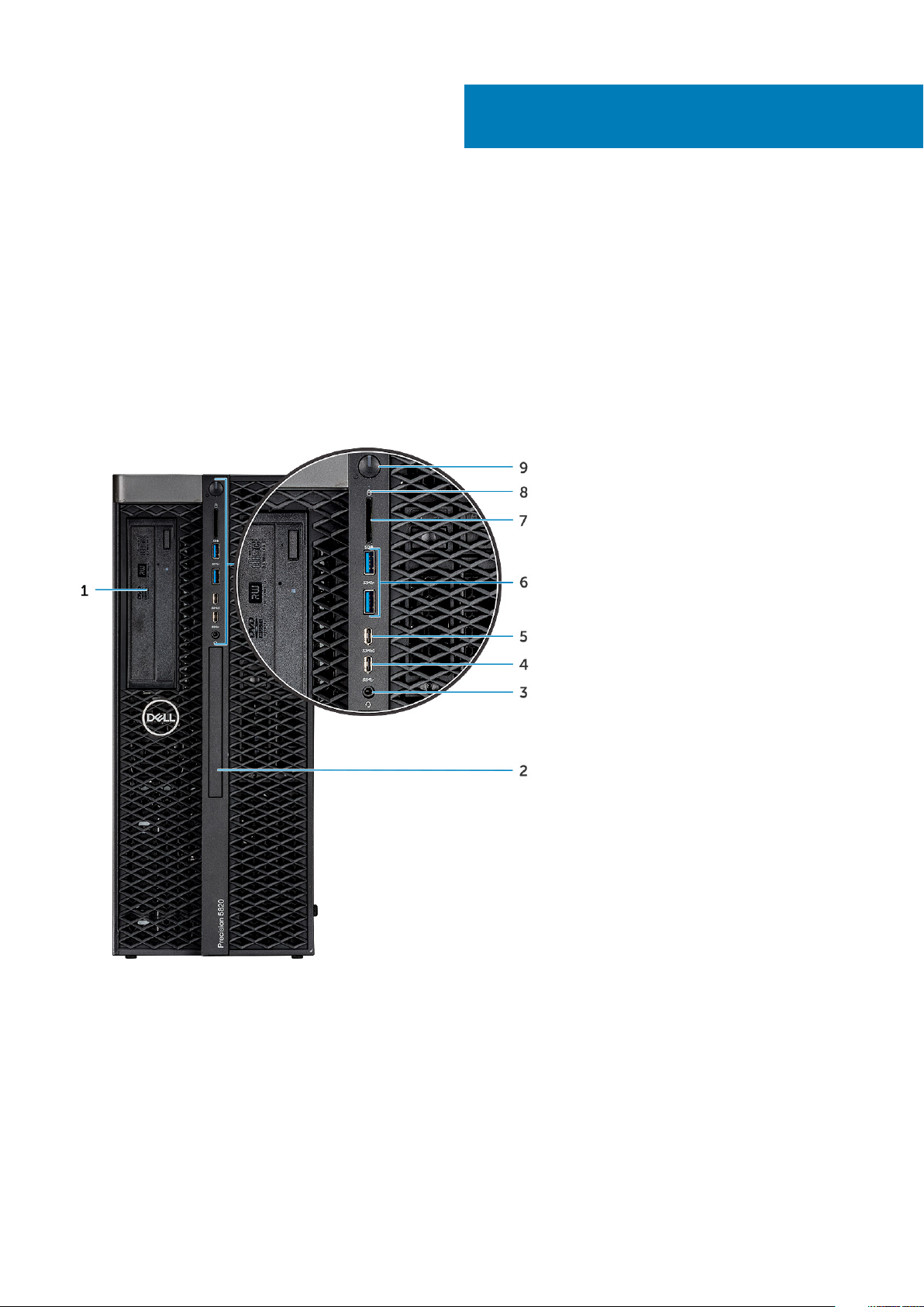
Front view
1
1. 5.25 inch ODD bracket 2. Slim optical disk drive
3. Headset port 4. USB 3.1 Gen 1 Type C
5. USB 3.1 Gen 1 Type C port with PowerShare 6. USB 3.1 Gen 1 ports
7. SD card slot 8. HDD activity LED
9. Power button
Chassis 7
Page 8
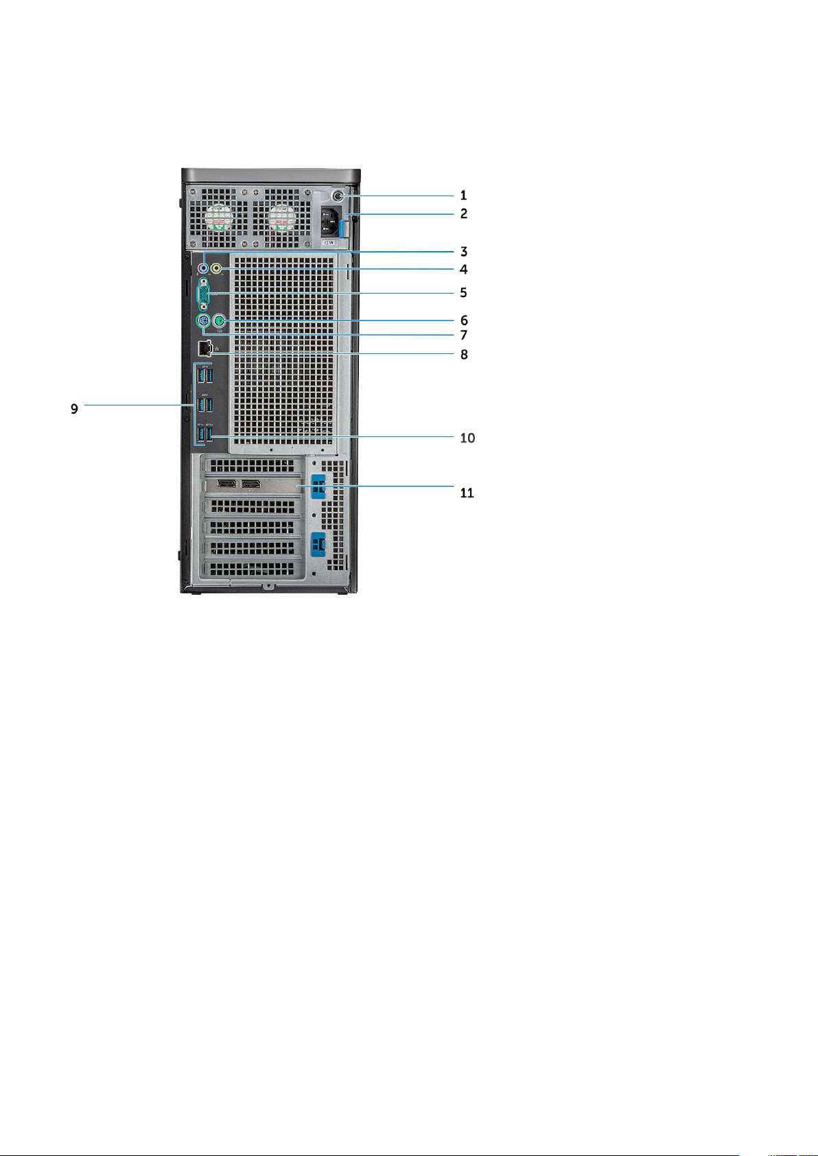
Back view
1. PSU BIST LED 2. Power cable connector
3. Microphone /Line-in port 4. Line-out port
5. Serial port 6. PS/2 Mouse port
7. PS/2 Keyboard port 8. Network port
9. USB 3.1 Gen1 ports 10. USB 3.1 Gen1 port(supports smart Power-On)
11. PCIe expansion slot
8 Chassis
Page 9
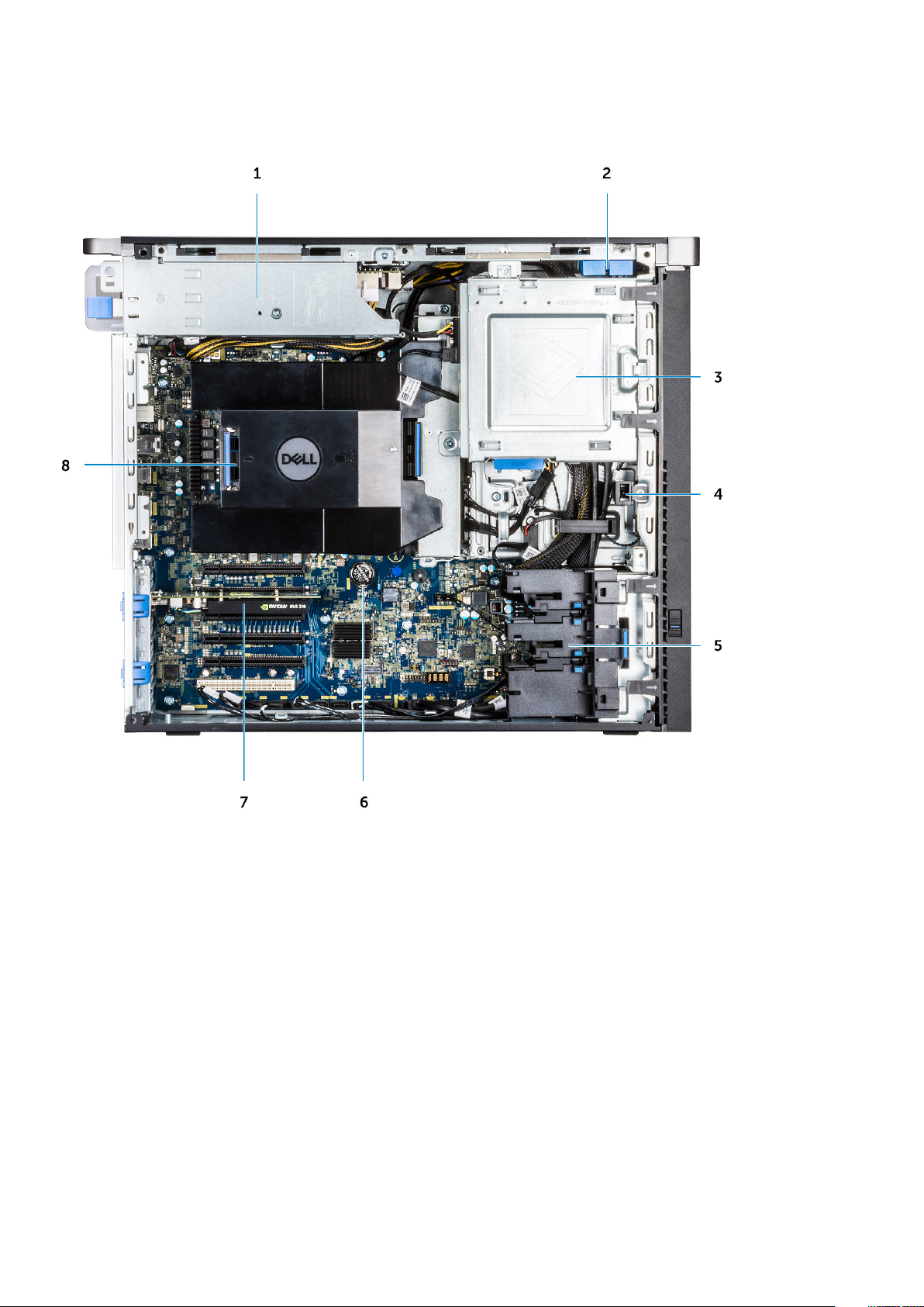
Internal view
1. PSU bracket 2. HDD bezel lock/unlock button
3. ODD 5.25" bracket 4. Intrusion switch
5. PCIe holder 6. Coin cell battery
7. Powered GPU 8. Air shroud
Chassis 9
Page 10
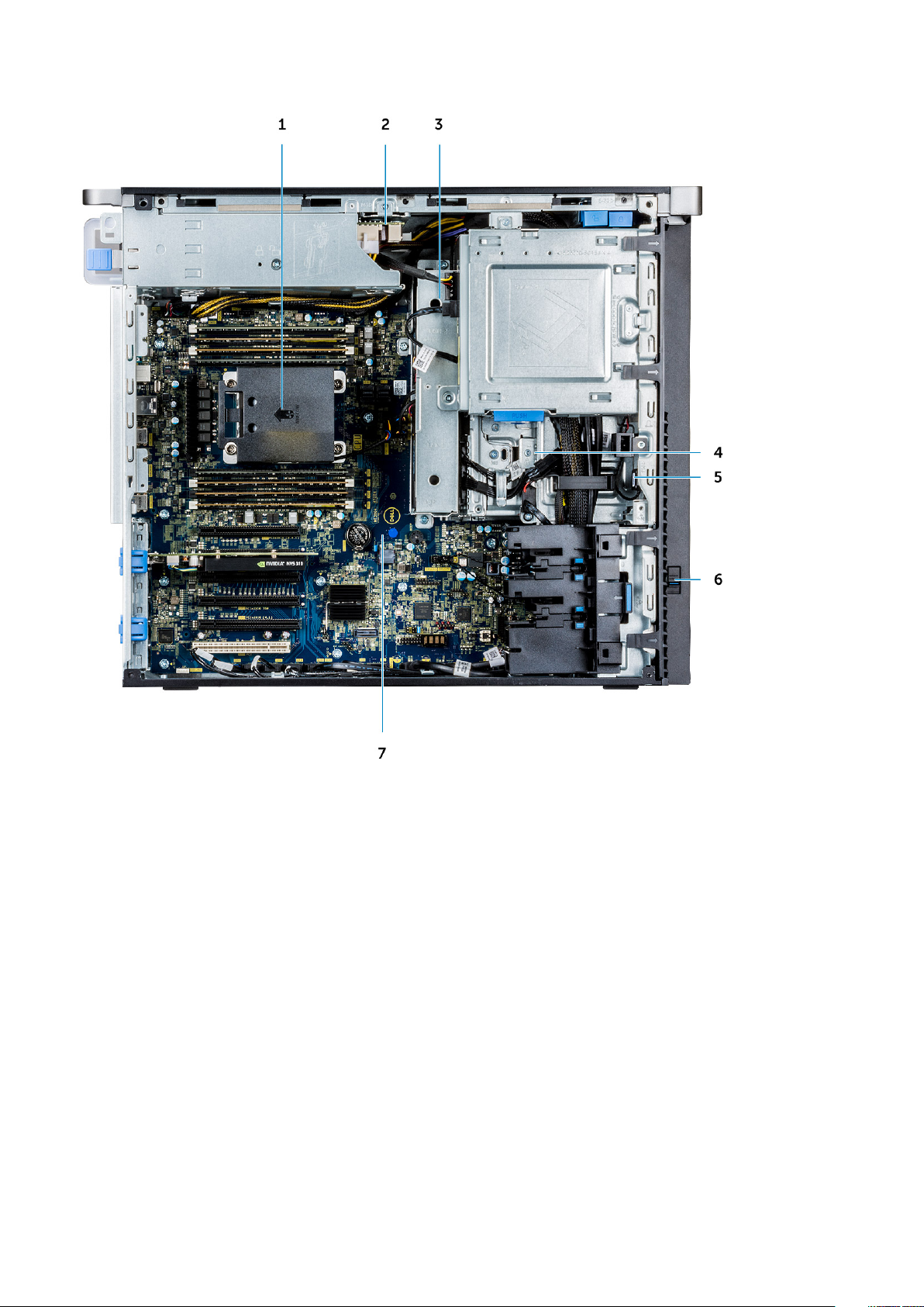
1. Heat sink 2. PSU distribution board
3. HDD fan 4. Flex bay
5. Speaker 6. Drive access release latch
7. System board
10 Chassis
Page 11
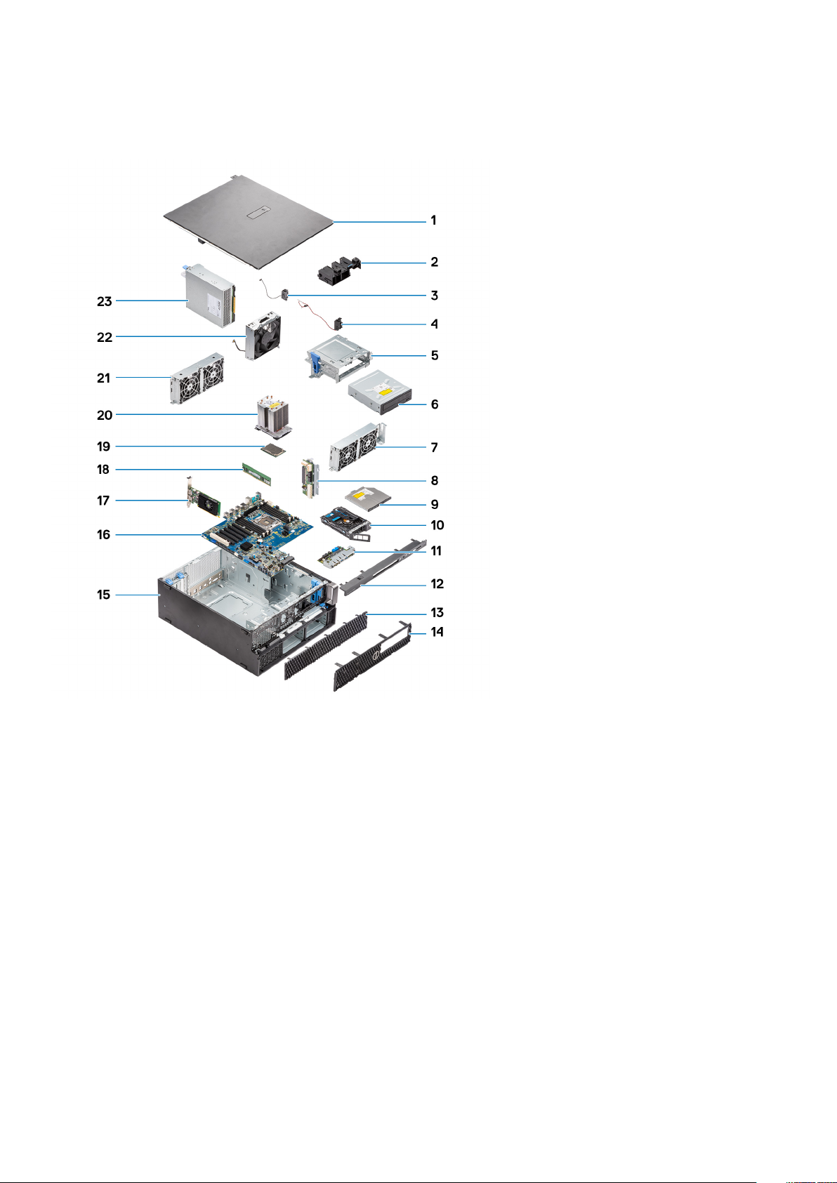
Major components of your system
This section illustrates the major components of your system along with its location.
1. Side cover
2. PCIe holder
3. Internal chassis speaker
4. Intrusion switch
5. 5.25 inch ODD bracket
6. 5.25 inch Optical Disk Drive
7. System fan
8. Power Distribution Board
9. Slim Optical Disk Drive
10. NVMe Flexbay
11. Front input and output panel
12. Front input and output bezel
13. Hard Disk Drive bezel
14. Front bezel
15. Computer chassis
16. System board
17. Expansion card
18. Memory
19. Processor
20. Heat sink and CPU fan assembly
21. System fan
Chassis
11
Page 12

22. Front system fan
23. Power supply unit (PSU)
NOTE: Dell provides a list of components and their part numbers for the original system configuration purchased. These
parts are available according to warranty coverages purchased by the customer. Contact your Dell sales representative
for purchase options.
12 Chassis
Page 13
2
Working on your computer
Topics:
• Safety instructions
• Turning off your computer — Windows
• Before working inside your computer
• After working inside your computer
Safety instructions
Use the following safety guidelines to protect your computer from potential damage and to ensure your personal safety. Unless otherwise
noted, each procedure included in this document assumes that the following conditions exist:
• You have read the safety information that shipped with your computer.
• A component can be replaced or, if purchased separately, installed by performing the removal procedure in reverse order.
NOTE: Disconnect all power sources before opening the computer cover or panels. After you finish working inside the
computer, replace all covers, panels, and screws before connecting to the power source.
WARNING: Before working inside your computer, read the safety information that shipped with your computer. For
additional safety best practices information, see the Regulatory Compliance Homepage
CAUTION: Many repairs may only be done by a certified service technician. You should only perform troubleshooting and
simple repairs as authorized in your product documentation, or as directed by the online or telephone service and
support team. Damage due to servicing that is not authorized by Dell is not covered by your warranty. Read and follow
the safety instructions that came with the product.
CAUTION: To avoid electrostatic discharge, ground yourself by using a wrist grounding strap or by periodically touching
an unpainted metal surface at the same time as touching a connector on the back of the computer.
CAUTION: Handle components and cards with care. Do not touch the components or contacts on a card. Hold a card by
its edges or by its metal mounting bracket. Hold a component such as a processor by its edges, not by its pins.
CAUTION: When you disconnect a cable, pull on its connector or on its pull-tab, not on the cable itself. Some cables
have connectors with locking tabs; if you are disconnecting this type of cable, press in on the locking tabs before you
disconnect the cable. As you pull connectors apart, keep them evenly aligned to avoid bending any connector pins. Also,
before you connect a cable, ensure that both connectors are correctly oriented and aligned.
NOTE: The color of your computer and certain components may appear differently than shown in this document.
CAUTION: System will shut down if side covers are removed while the system is running. The system will not power on
if the side cover is removed.
Turning off your computer — Windows
CAUTION:
computer or remove the side cover.
To avoid losing data, save and close all open files and exit all open programs before you turn off your
1. Click or tap .
2. Click or tap
and then click or tap Shut down.
Working on your computer 13
Page 14

NOTE: Ensure that the computer and all attached devices are turned off. If your computer and attached devices did
not automatically turn off when you shut down your operating system, press and hold the power button for about 6
seconds to turn them off.
Before working inside your computer
To avoid damaging your computer, perform the following steps before you begin working inside the computer.
1. Ensure that you follow the Safety Instructions.
2. Ensure that your work surface is flat and clean to prevent the computer cover from being scratched.
3. Turn off your computer.
4. Disconnect all network cables from the computer.
CAUTION: To disconnect a network cable, first unplug the cable from your computer and then unplug the cable from
the network device.
5. Disconnect your computer and all attached devices from their electrical outlets.
6. Press and hold the power button while the computer is unplugged to ground the system board.
NOTE: To avoid electrostatic discharge, ground yourself by using a wrist grounding strap or by periodically touching
an unpainted metal surface at the same time as touching a connector on the back of the computer.
After working inside your computer
After you complete any replacement procedure, ensure that you connect any external devices, cards, and cables before turning on your
computer.
1. Connect any telephone or network cables to your computer.
CAUTION:
computer.
2. Connect your computer and all attached devices to their electrical outlets.
3. Turn on your computer.
4. If required, verify that the computer works correctly by running the diagnostic tool.
To connect a network cable, first plug the cable into the network device and then plug it into the
14
Working on your computer
Page 15

Removing and installing components
Topics:
• Screw size list
• Recommended tools
• Side cover
• Power supply unit (PSU)
• Front bezel
• Hard Disk Drive bezel
• Hard disk drive assembly
• NVMe Flexbay
• Slim Optical Disk Drive
• Front input and output bezel
• Optical Disk Drive
• 5.25 inch ODD bracket
• Front input and output panel
• Input and output panel bracket
• Intrusion switch
• Internal chassis speaker
• Air shroud
• Memory
• PCIe NVMe card
• Expansion card
• Coin cell battery
• System fan
• Fan bracket
• PCIe holder
• Heat sink and CPU fan assembly
• Processor
• Front system fan
• VROC module
• System board
• RAID controller battery
• RAID controller battery bracket
3
Screw size list
Table 1. Screw list
Component Screw type Quantity
Slim ODD Bracket #6-32 UNC X6.0mm 1
FIO Cable Clip #6-32X1/4 inches 1
FIO Board M3X6.5mm 2
FIO Bracket #6-32 UNC X6.0mm 1
Front System Fan Bracket #6-32 UNC X6.0mm 1
Intrusion Holder M3X6.5mm 1
PDB Board #6-32X1/4 inches 3
Removing and installing components 15
Page 16

Component Screw type Quantity
PDB Bracket M3X6.5mm 1
Slim ODD Plug M3X6.5mm 2
HDD Bracket M3X6.5mm 1
5.25" ODD Bracket
System Board #6-32X1/4 inches 10
Middle Fan Fixed Bracket #6-32X1/4 inches 1
Middle Fan Bracket #6-32X1/4 inches 3
Rear Fan Bracket #6-32X1/4 inches 2
HSBP Board M3X6.5mm 2
Slim ODD Fixed Bracket M2X2.0mm 2
Slim ODD M3X6.5mm 1
5.25" ODD M3X4.5mm 4
3.5" HDD Bracket M3X4.5mm 4
2.5" HDD Bracket M3X4.5mm 4
2nd CPU Support Bracket #6-32X1/4 inches 2
2nd CPU Board #6-32X1/4 inches 5
UPI Fixed Bracket M3X5.0mm 1
CPU Cooler T-30 torx bolt 4
Liquid Cooler Module
• #6-32 UNC X6.0mm
• M3X6.5mm
• #6-32X1/4 inches
• #6-32 UNC X3.5mm
• T-30 torx bolt
• 2
• 2
• 4
• 6
• 4
M.2 Carrier Cover
• M2X6mm
• M2X3mm
Recommended tools
The procedures in this document require the following tools:
• Phillips #0 screwdriver
• Phillips #1 screwdriver
• Philips #2 screwdriver
• Plastic scribe
NOTE: The #0 screw driver is for screws 0-1 and the #1 screw driver is for screws 2-4.
Side cover
Removing the side cover
1. Follow the procedure in Before working inside your computer.
CAUTION:
is removed while the system is on.
2. To remove the side cover:
The system will not power on while the side cover is off. Also, the system will shut down if the side cover
• 1
• 2
16
Removing and installing components
Page 17
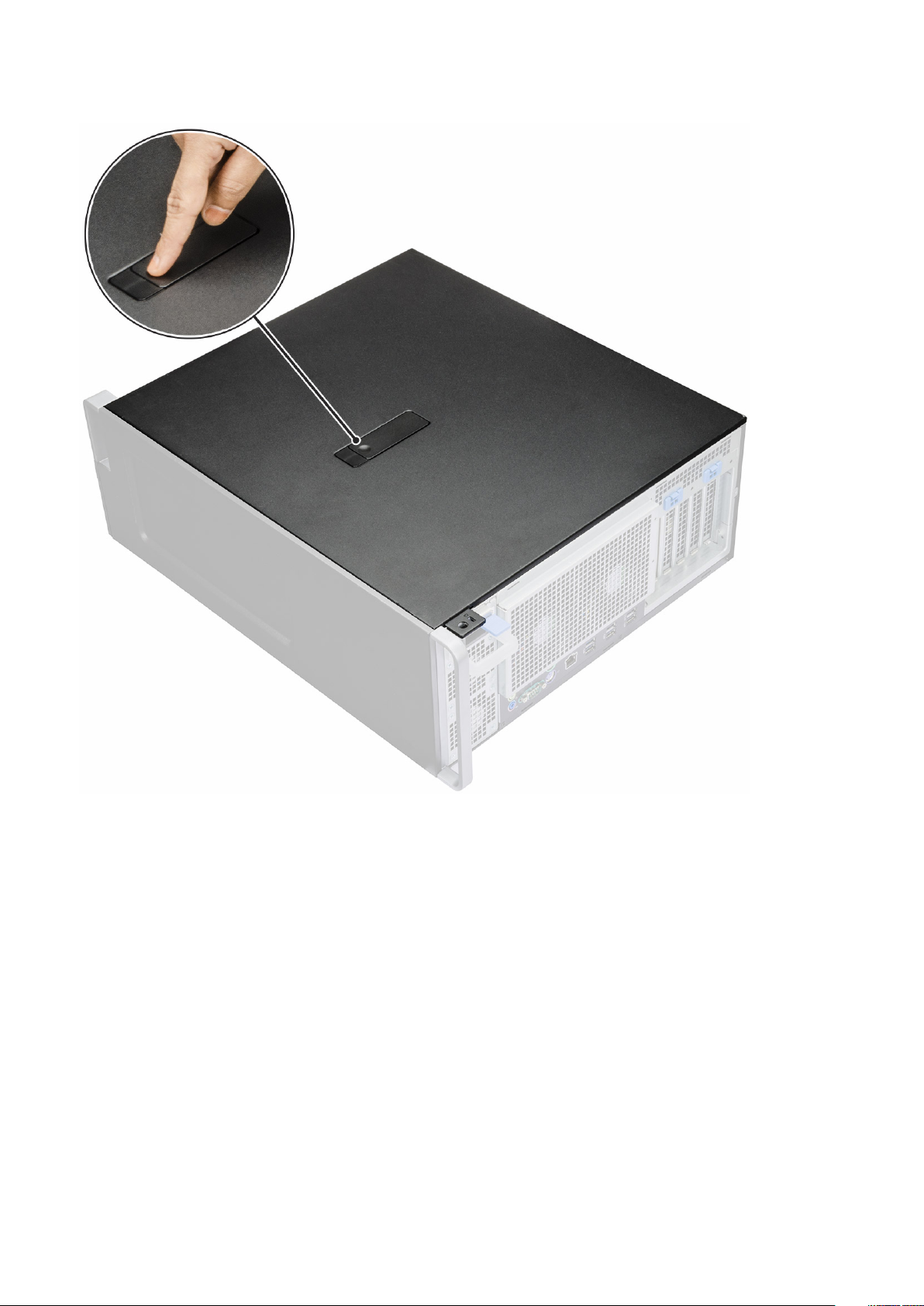
3. Press the latch
4. Pull the latch [1] upward and rotate it to release the cover [2].
Removing and installing components
17
Page 18
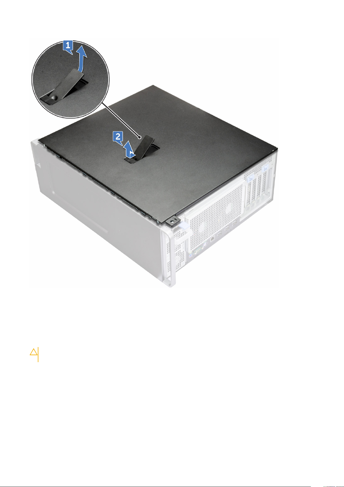
5. Lift the cover to remove it from the system.
Installing the side cover
1. First hold and align the bottom of the side cover to the chassis.
2. Ensure that the hook on the bottom of the side cover snaps into the notch on the system.
3. Press the system cover until it clicks into place.
CAUTION:
removed while the system is on.
4. Follow the procedure in After working inside your computer .
The system will not power on without the side cover. Also, the system will shut down if the side cover is
Power supply unit (PSU)
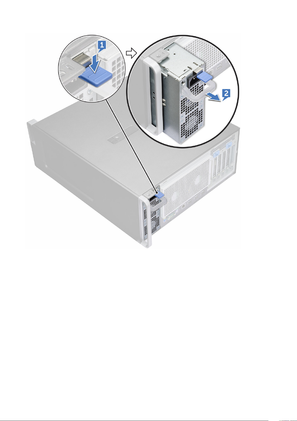
Removing the PSU
1. Follow the procedure in Before working inside your computer.
2. Disconnect the power cable from the system.
3. Press the PSU release latch [1] and slide the power supply away from the system [2].
18
Removing and installing components
Page 19
Installing the PSU
1. Slide in the power supply unit to the PSU slot on the system.
2. Connect the power cable to the system.
3. Follow the procedure in After working inside your computer
Front bezel
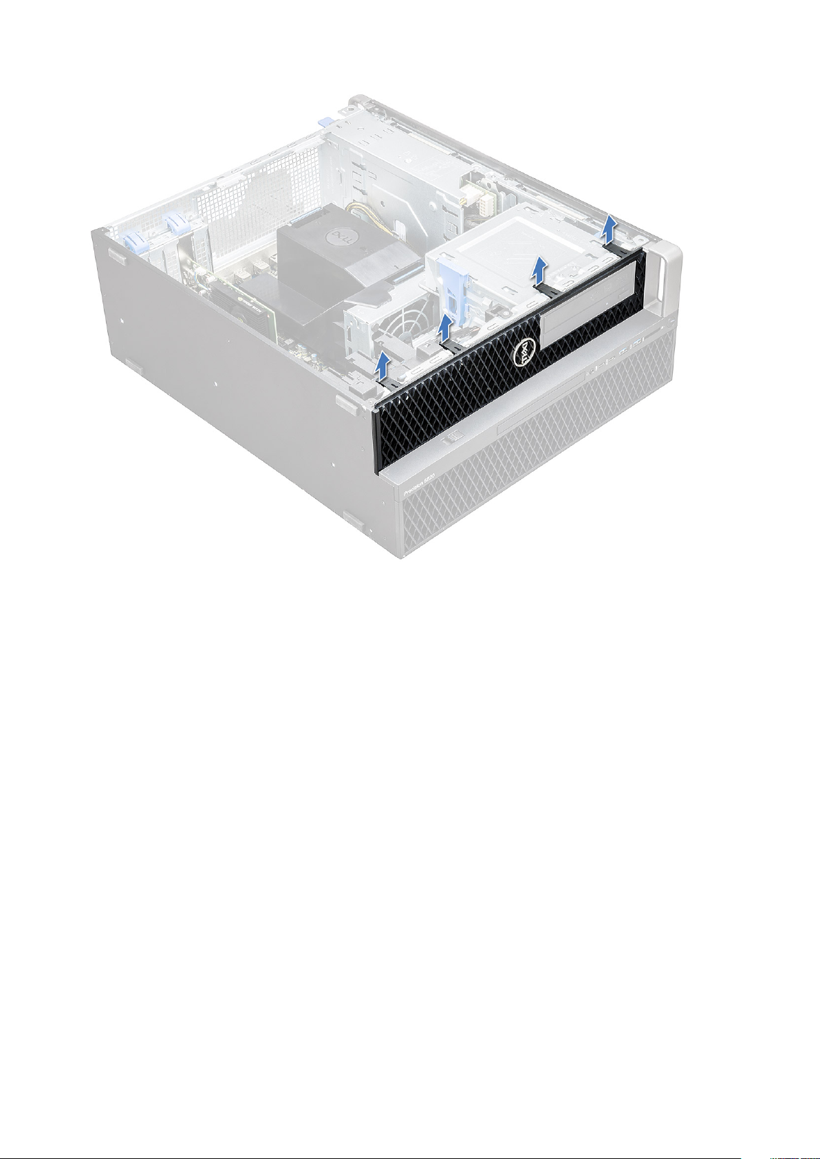
Removing the front bezel
1. Follow the procedure in Before working inside your computer.
2. Remove the side cover.
3. To remove the front bezel:
a) Press the latch and pry the retention tabs to release the front bezel from the system.
Removing and installing components
19
Page 20
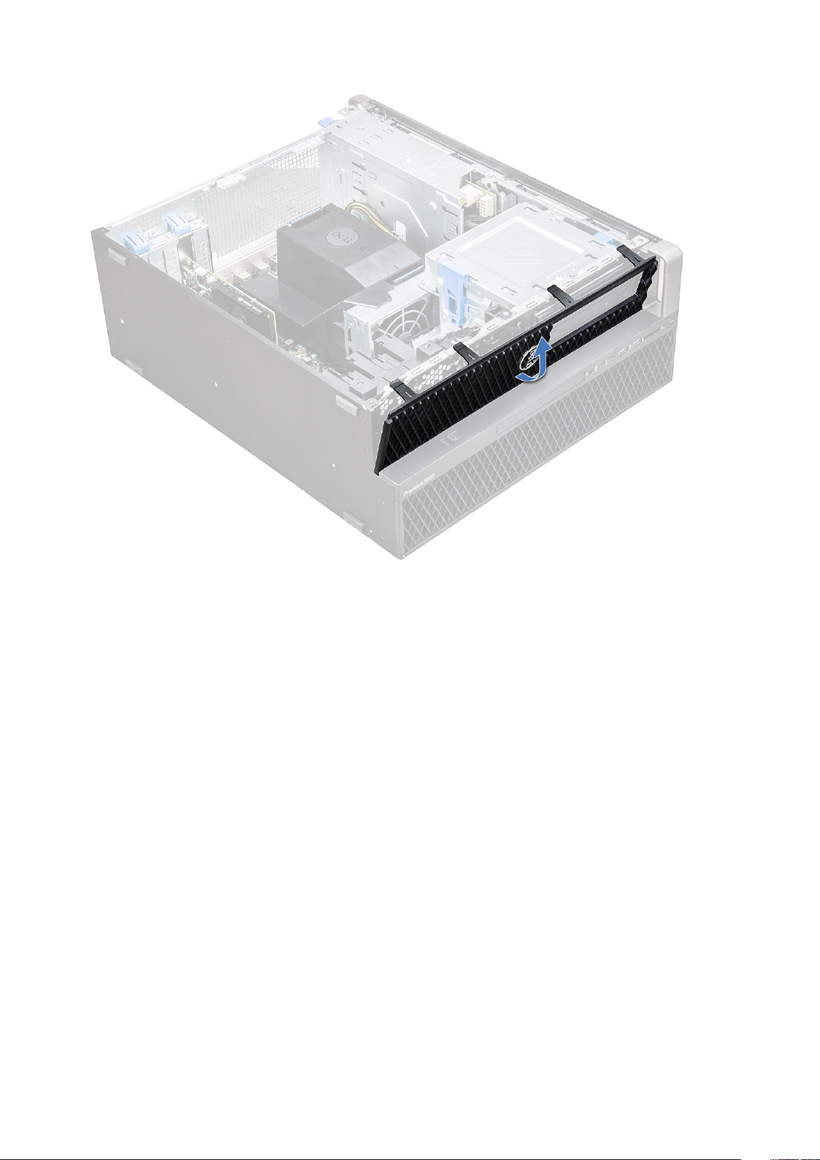
b) Rotate the bezel forward and lift the front bezel away from the system.
20
Removing and installing components
Page 21
Installing the front bezel
1. Hold the bezel and ensure that the hooks on the bezel snap into the notches on the system.
2. Rotate the bezel forward and press the front bezel until the tabs click into place.
3. Follow the procedure in After working inside your computer.
Hard Disk Drive bezel
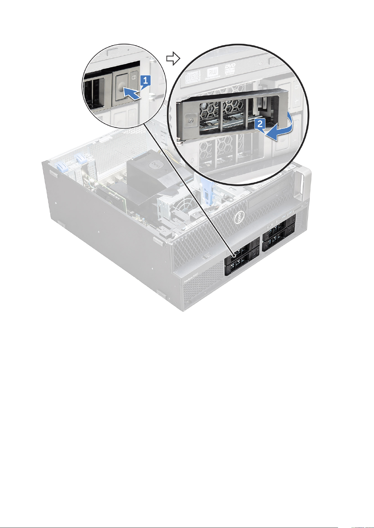
Removing HDD bezel
1. Follow the procedure in Before working inside your computer.
2. Remove the side cover.
3. To remove the HDD bezel:
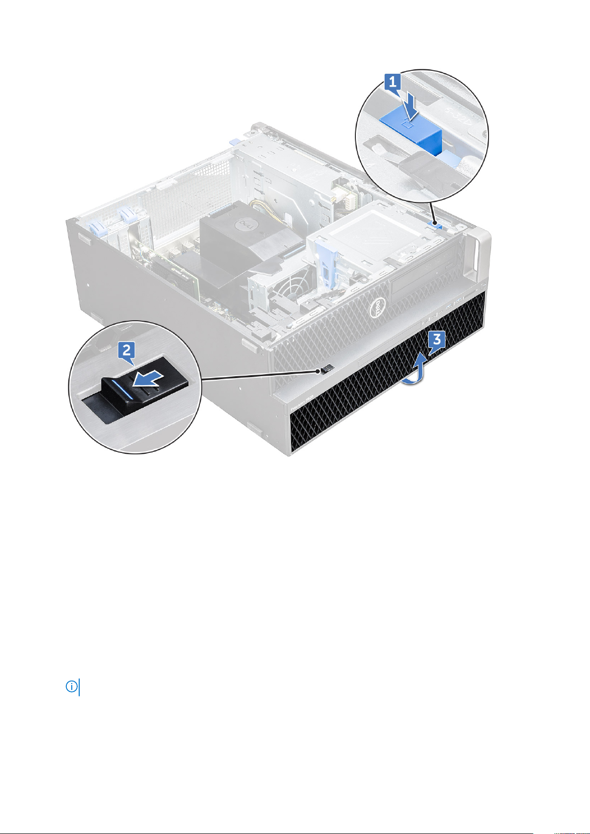
a) Press the blue unlock button [1] on the edge of ODD bay.
b) Slide the latch [2] to the unlock position, on the front I/O bezel.
c) Rotate forward and lift the HDD bezel [3] away from the system.
Removing and installing components
21
Page 22
Installing HDD bezel
1. Hold the bezel and ensure that the hooks on the bezel snap into the notches on the system.
2. Press the blue lock button on the left edge of the ODD bay to secure the bezel to the system.
3. Install the side cover.
4. Follow the procedure in After working inside your computer.
Hard disk drive assembly
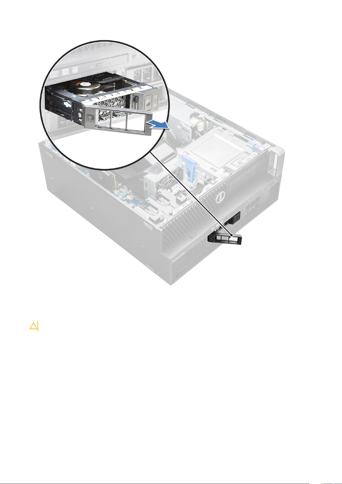
Removing the HDD carrier
1. Follow the procedure in Before working inside your computer.
2. Remove the:
a) side cover
NOTE: Do not remove the side cover, if the front I/O bezel is unlocked.
b) HDD bezel
3. To remove the HDD carrier:
a) Press the release button [1] to unlock the latch [2].
22
Removing and installing components
Page 23
b) Pull the latch to slide the carrier out of the HDD slot.
Removing and installing components
23
Page 24
Installing the HDD carrier
1. Slide the carrier into the drive bay until it clicks into place.
CAUTION: Ensure that the latch is open before installing the carrier.
2. Lock the latch.
3. Install the following components:
a) HDD bezel
b) side cover
4. Follow the procedure in After working inside your computer.
Removing the HDD
1. Follow the procedure in Before working inside your computer.
2. Remove the following:
a) side cover
b) HDD bezel
c) HDD carrier
3. To remove the 3.5 inch HDD:
24
Removing and installing components
Page 25
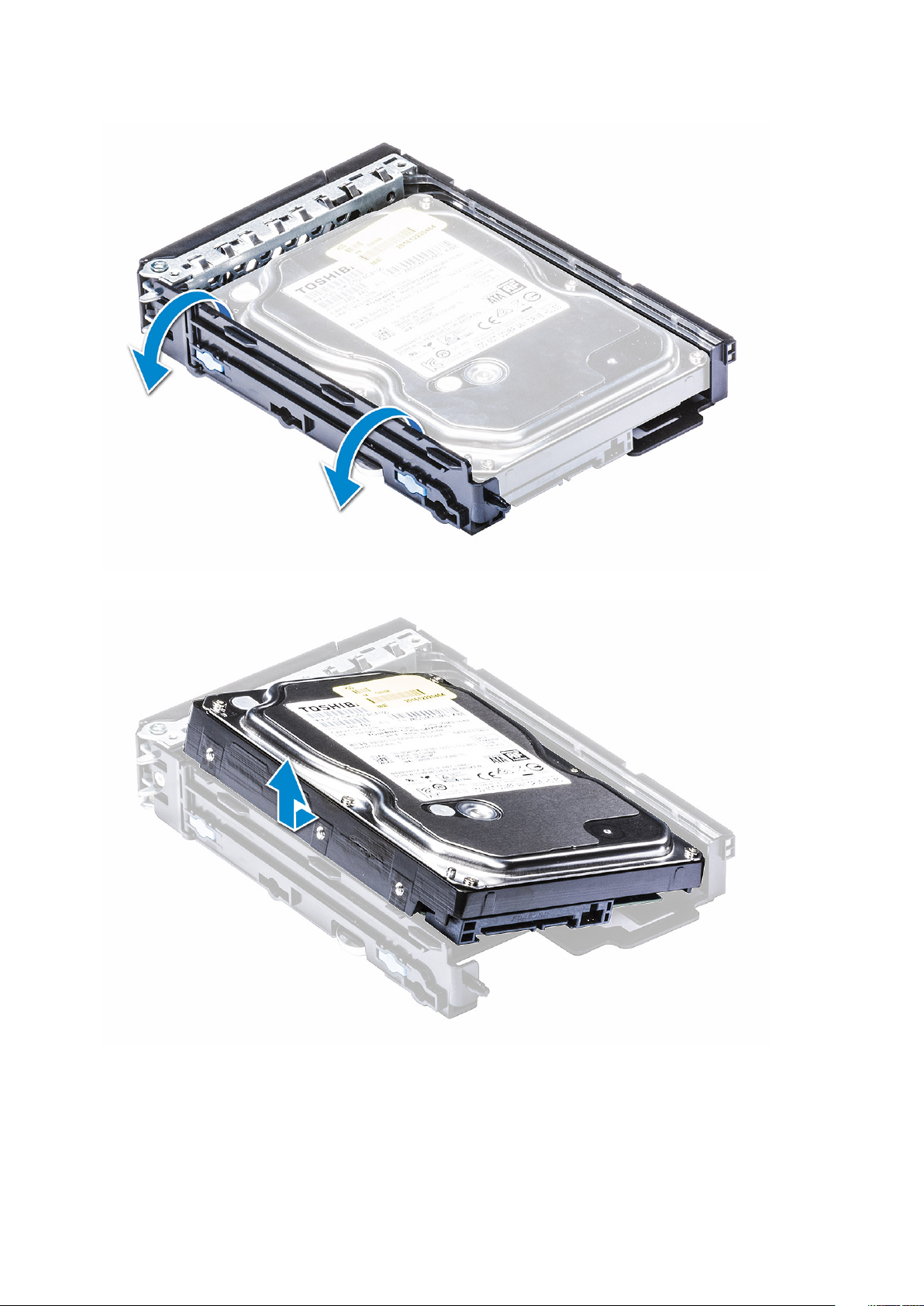
a) Expand one side of the carrier.
b) Lift the hard drive out of the carrier.
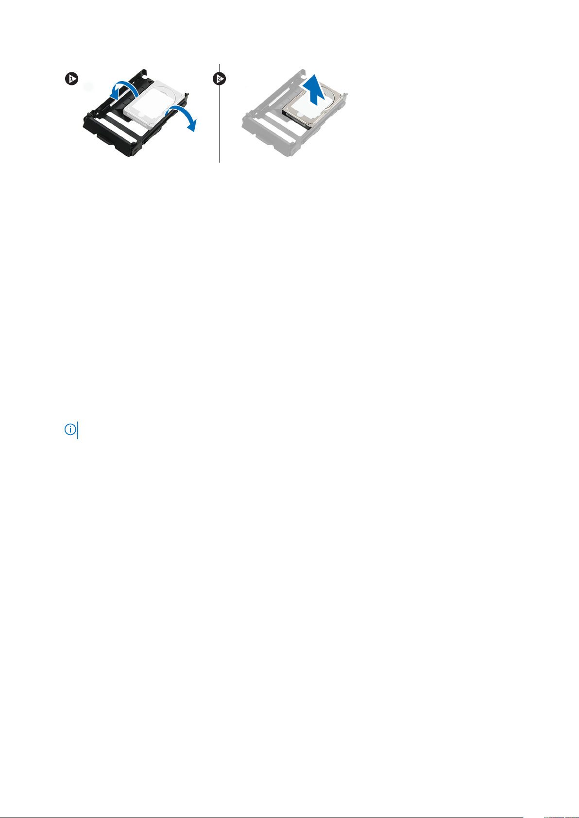
4. To remove the 2.5 inch HDD:
a) Expand two sides of the carrier.
b) Lift the hard drive out of the carrier.
Removing and installing components
25
Page 26
Installing the HDD
1. Insert the HDD to its slot in the HDD bracket with the connector end of the hard drive towards the back of the HDD carrier.
2. Slide the HDD carrier back into the hard drive bay.
3. Install the following:
a) HDD carrier
b) HDD bezel
c) side cover
4. Follow the procedure in After working inside your computer
NVMe Flexbay
Removing the NVMe Flexbay
1. Follow the procedure in Before working inside your computer.
2. Remove the:
a) side cover
NOTE: Do not remove the side cover, if the front I/O bezel is unlocked.
b) HDD bezel
3. To remove the NVMe flexbay:
a) Press the release button [1] to unlock the latch [2].
26
Removing and installing components
Page 27

b) Pull the latch to slide the carrier out of the HDD slot.
Removing and installing components
27
Page 28
4. To remove the SSD carrier from the NVMe flexbay:
a) Press the release button to slide the M.2 SSD carrier out of the NVMe flexbay.
b) Pull the M.2 SSD carrier out of the NVMe flexbay.
28
Removing and installing components
Page 29
5. To remove the SSD from the SSD carrier:
a) Remove the screws on either side of the SSD.
b) Remove the screw from the top of the SSD carrier.
Removing and installing components
29
Page 30
c) Slide the SSD cover from the top of the carrier.
d) Slide the SSD out of the M.2 slot on the carrier.
30
Removing and installing components
Page 31

Installing the NVMe flexbay
1. To install the SSD in the carrier:
a) Remove the dummy SSD blank from the SSD carrier.
b) Peel off the tape from the SSD carrier.
Removing and installing components
31
Page 32

c) Peel off the adhesive tape from the SSD carrier cover.
2. Install the SSD in the carrier
32
Removing and installing components
Page 33

3. Replac the two side screws and the central screw.
4. To install the SSD carrier slide the carrier in the NVMe flexbay until it clicks in place.
5. Slide the carrier into the drive bay until it clicks into place.
CAUTION: Ensure that the latch is open before installing the carrier.
6. Lock the latch.
7. Install the following components:
a) HDD bezel
b) side cover
8. Follow the procedure in After working inside your computer.
Slim Optical Disk Drive
Removing the slim ODD
1. Follow the procedure in Before working inside the computer.
2. Remove the side cover.
3. To remove the slim ODD:
a) Remove the screw [1] that secures the slim ODD and push the slim ODD [2] out of the chassis.
Removing and installing components
33
Page 34

b) Slide the slim ODD out of the system.
34
Removing and installing components
Page 35

Installing the slim ODD
1. Slide the slim ODD into the slot on the chassis.
2. Tighten the screw to secure the slim ODD to the chassis.
3. Install the side cover.
4. Follow the procedure in After working inside your computer.
Front input and output bezel
Removing front input and output bezel
1. Follow the procedure in Before working inside your computer.
2. Remove the:
a) side cover
b) front bezel
3. To remove the front input and output(I/O) bezel:
a) Pry the four retention tabs[1] from the chassis and push the bezel out from the chassis[2].
Removing and installing components
35
Page 36

b) Lift the bezel from the chassis.
36
Removing and installing components
Page 37

Installing front input and output bezel
1. Hold the input and output(I/O) bezel and ensure that the hooks on the bezel snap into the notches on the system.
2. Press the retention tabs and secure them to the chassis.
3. Install the :
a) front bezel
b) side cover
4. Follow the procedure in After working inside your computer.
Optical Disk Drive
Removing the ODD
1. Follow the procedure in Before working inside your computer.
2. Remove the:
a) side cover
b) front bezel
3. To remove the ODD:
a) Remove the optical drive data cable and optical drive power cable from the ODD.
Removing and installing components
37
Page 38

b) Push the optical drive release button[1] and push the optical drive out of the system.
c) Slide the ODD[2] from the ODD bracket.
38
Removing and installing components
Page 39

Installing the ODD
1. Place the ODD into the 5.25" ODD bracket.
2. Slide the ODD and lock the latch by a click.
3. Connect the optical drive data cable and optical drive power cable to the ODD.
4. Install the:
a) front bezel
b) side cover
5. Follow the procedure in After working inside your computer
5.25 inch ODD bracket
Removing the 5.25 ODD bracket
1. Follow the procedure in Before working inside your computer.
2. Remove the:
a) side cover
b) front bezel
c) ODD
3. To remove the ODD bracket:
a) Remove the five screws[1,2] that secure the bracket to the chassis.
Removing and installing components
39
Page 40

b) Slide the ODD bracket toward the rear of the system and lift it away from the chassis.
40
Removing and installing components
Page 41

Installing the 5.25 ODD bay
1. Place the ODD bracket into the system slot.
2. Replace the (6-32 X 6.0mm) screws.
3. Install the:
a) ODD
b) front bezel
c) side cover
4. Follow the procedure in After working inside your computer
Front input and output panel
Removing front input and output panel
1. Follow the procedure in Before working inside your computer.
2. Remove the:
a) side cover
b) front bezel
c) front input and output bezel
d) 5.25 inch ODD bracket
3. To remove the front input and output(I/O) panel:
a) Disconnect the intrusion switch cable [1], USB 3.1 cable [2], front I/O power cable [3], USB 3.1 cable [4], Speaker cable [5], Audio
cable [6]
Removing and installing components
41
Page 42

NOTE: Do not pull the connector by the cable wires. Instead, disconnect the cable by pulling the connector end.
Pulling the cable wires may loosen them from the connector.
b) Remove the screw[1] that secures the front I/O panel to the chassis and slide the I/O panel out of the chassis[2].
42
Removing and installing components
Page 43

Installing front input and output panel
1. Insert the input and output(I/O) panel onto its slot in the system.
2. Slide the panel to secure the hooks into the chassis hole.
3. Tighten the screw to secure the front I/O panel to the chassis.
4. Connect the following cables:
• intrusion switch cable
• USB 3.1 cable
• front I/O power cable
• front I/O power cable
• USB 3.1 cable
• speaker cable
• audio cable
5. Install the:
a) front input and output bezel
b) 5.25 inch ODD bracket
c) front bezel
d) side cover
6. Follow the procedure in After working inside your computer.
Removing and installing components
43
Page 44

Input and output panel bracket
Removing input and output panel bracket
1. Follow the procedure in Before working inside your computer.
2. Remove the:
a) side cover
b) front bezel
c) front input and output bezel
d) 5.25 inch ODD bracket
e) front input and output panel
3. To remove the input and output(I/O) panel bracket:
a) Remove the two screws.
b) Slide the I/O module out of the bracket.
44
Removing and installing components
Page 45

Installing input and output panel bracket
1. Insert the input and output(I/O) panel into the metal bracket.
2. Replace the screws to secure the I/O panel bracket to the I/O panel.
3. Install the:
a) front input and output panel
b) front input and output bezel
c) 5.25 inch ODD bracket
d) front bezel
e) side cover
4. Follow the procedure in After working inside your computer.
Intrusion switch
Removing the Intrusion switch
1. Follow the procedure in Before working inside your computer.
2. Remove the:
a) side cover
b) front bezel
c) 5.25 inch ODD bracket
3. To remove the intrusion switch:
a) Disconnect the intrusion cable [1] from the I/O module.
b) Remove the screw [2] that secures the intrusion switch to the chassis.
c) Lift the intrusion switch and remove it from the chassis.
NOTE: The system will not power on without the intrusion switch installed.
Removing and installing components 45
Page 46

Installing the intrusion switch
1. Place the intrusion switch into the slot in the system chassis.
2. Replace the screw and secure the switch to the chassis.
3. Connect the cable to the system board.
4. Install the:
a) 5.25 inch ODD bracket
b) front bezel
c) side cover
5. Follow the procedure in After working inside your computer.
Internal chassis speaker
Removing the internal chassis speaker
1. Follow the procedure in Before working inside your computer.
2. Remove the: .
46
Removing and installing components
Page 47

a) side cover
b) front bezel
c) 5.25 inch ODD bracket
3. To remove the internal chassis speaker:
a) Disconnect the speaker cable [1] from the front I/O module.
b) Press the speaker securing tabs [2], then pull to release it from the system.
c) Gently push the speaker [3] with its cable out of the system.
Installing the internal chassis speaker
1. Press and hold the tabs on either side of the intrusion speaker, and slide the speaker module into the slot to secure it to the system.
2. Connect the internal chassis speaker cable to the connector on the system chassis.
3. Install the:
a) 5.25 inch ODD bracket
b) front bezel
c) side cover
4. Follow the procedure in After working inside your computer
Removing and installing components
47
Page 48

Air shroud
Removing the air shroud
1. Follow the procedure in Before working inside your computer.
2. Remove the side cover
3. To remove the air shroud:
a) Press in the securing tabs by holding the air shroud from both the ends, and then lift the air shroud from the system.
48 Removing and installing components
Page 49

Removing and installing components 49
Page 50

Installing the air shroud
1. Arrange CPU power cables before installing.
2. Place the shroud into its position.
3. Make sure that the two securing holes of the air shroud is completely inserted into the two holes on the middle fan bracket and the
other latch is fixed on the cooler.
4. Press down the shroud to lock it with a click.
5. Install the side cover.
6. Follow the procedure in After working inside your computer.
Memory
Removing the memory module
1. Follow the procedure in Before working inside your computer.
2. Remove the following:
a) side cover
b) air shroud
3. Press the memory module retention tabs on each side of the memory module.
4. Lift the memory module out of the memory slot on the system board.
WARNING:
straight out of the memory module slot.
Rotating the memory module out of the slot will cause damage to the memory module. Ensure to pull it
Installing the memory module
1. Align the notch on the memory module with the tab on the memory module connector.
2. Insert the memory module into the memory module slot.
3. Press the memory module firmly until the retention tabs click into place.
NOTE:
Do not pull the retention levers up. Always press down firmly on the module until the levers lock into place
unassisted.
4. Install the:
a) air shroud
b) side cover
5. Follow the procedure in After working inside your computer
PCIe NVMe card
Removing the PCIe NVMe card
1. Follow the procedure in Before working inside your computer.
50
Removing and installing components
Page 51

2. Remove the side cover.
3. To remove the PCIe NVMe card:
a) Press and rotate the locking latch backward, to unlock the filler bracket [1].
b) Lift the PCIe NVMe card from the PCIe slot on the system board [2] .
Installing the PCIe NVMe card
1. Align and place the PCIe NVMe card to the PCIe slot on the system board.
2. Press it down so that it is securely seated on the slot.
3. Rotate both the locking latch forward, on the filler bracket, to secure the expansion card to the system board.
4. Install the side cover.
5. Follow the procedure in After working inside your computer.
Expansion card
Removing the expansion card
1. Follow the procedure in Before working inside your computer.
2. Remove the side cover.
3. To remove the expansion card:
NOTE: For expansion card with VGA power, disconnect the data or power cable connected to the expansion card.
a) Press [1] and rotate the expansion card locking latch backward [2], to unlock the filler bracket.
b) Lift the expansion card [3] from the PCIe slot on the system board.
Removing and installing components
51
Page 52

Installing the expansion card
1. Align and place the expansion card to the PCIe slot on the system board.
2. Press it down so that it is securely seated on the slot.
NOTE: For expansion card with VGA power, connect the data or power cable to the expansion card.
3. Rotate both the expansion card locking latch forward, on the filler bracket, to secure the expansion card to the system board.
4. Install the side cover.
5. Follow the procedure in After working inside your computer.
Coin cell battery
Removing the coin cell battery
1. Follow the procedure in Before working inside your computer.
2. Remove the:
a) side cover
3. To remove the coin cell battery:
a) Press the release latch [1] away from the battery to allow the battery to pop-up from the socket [2].
52
Removing and installing components
Page 53

b) Lift the coin-cell battery out of the system board.
Installing the coin cell battery
1. Place the coin-cell battery into its slot on the system board.
2. Press the coin-cell battery with positive (+) side facing up until the release latch springs back into place and secures it to the system
board.
3. To install:
a) side cover
4. Follow the procedure in After working inside your computer.
System fan
Removing the System fan
1. Follow the procedure in Before working inside your computer .
2. Remove the:
a) side cover
b) air shroud
Removing and installing components
53
Page 54

c) front bezel
d) ODD
e) 5.25 inch ODD bracket
3. To remove the system fan:
a) Press the connector tab and disconnect the two fan cables from the system board.
NOTE: Do not pull the connector by the cable wires. Instead, disconnect the cable by pulling on the connector
end. Pulling on the cable wires may loosen them from the connector.
b) Remove the screws [1] securing the system fan to the system board and lift the system fan up [2] .
54
Removing and installing components
Page 55

Installing the system fan
1. Align the system fan to its slot on the system board and secure it with the 3 screws.
2. Connect the fan cables to the slot on the system board.
3. Install the:
a) 5.25 ODD bracket
b) ODD
c) front bezel
d) air shroud
e) side cover
4. Follow the procedure in After working inside your computer.
Fan bracket
Removing the fan from the fan bracket
1. Follow the procedure in Before working inside your computer.
2. Remove the:
a) side cover
b) system fan
3. To remove the fan from the fan bracket:
a) Slide out the four rubber grommets for each fan from the fan chassis [1].
b) Lift the fan and remove it from the fan assembly [2].
Removing and installing components
55
Page 56

Installing the fan into the fan bracket
1. Place the fan into the fan bracket.
2. Tighten the grommets that secure the fan to the fan bracket.
3. Install the:
a) system fan
b) side cover
4. Follow the procedure in After working inside your computer
56
Removing and installing components
Page 57

PCIe holder
Removing PCIe holder
1. Follow the procedure in Before working inside your computer.
2. Remove the:
a) side cover
b) expansion card
3. To remove the PCIe holder:
a) Press the PCIe holder securing clip [1] and slide the holder [2] out of the chassis.
Installing the PCIe holder
1. Align and place the PCIe holder to the system chassis.
2. Press the holder back until it clicks to the system.
3. Install the:
a) side cover
4. Follow the procedure in After working inside your computer.
Removing and installing components
57
Page 58

Heat sink and CPU fan assembly
Removing the heat sink and CPU fan assembly
1. Follow the procedure in Before working inside your computer.
2. Remove the:
a) side cover
b) air shroud
3. To remove the heat sink and CPU fan assembly:
a) Disconnect the CPU fan cable [1] from the system board.
b) Loosen the four heat sink captive screws [2], in the diagonal order (4, 3, 2, 1).
c) Gently lift the heat sink and CPU fan assembly [3] from the system.
NOTE: Lay the assembly with the thermal grease facing up.
Installing heat sink and CPU fan assembly
1. Place the heat sink and CPU fan assembly on the CPU slot.
58
Removing and installing components
Page 59

2. Replace the four screws in the diagonal order (1,2,3,4), to secure the heat sink and CPU fan assembly to the system board.
NOTE: When installing the heat sink and CPU fan assembly into the system ensure that the airflow arrow is pointed
towards the rear of the system.
3. Connect the CPU fan cable to the system board.
4. Install the:
a) air shroud
b) side cover
5. Follow the procedure in After working inside your computer.
Removing the CPU fan
1. Follow the procedure in Before working inside your computer.
2. Remove the:
a) side cover
b) air shroud
c) heat sink and CPU fan assembly
3. To remove the CPU fan:
a) Unroute the CPU fan cable from the cable holder in the bracket.
b) Lay the assembly with the thermal grease facing up.
c) Remove the four screws [1] securing the heat sink and the CPU fan assembly.
d) Gently lift the heat sink [2] away from the CPU fan.
Removing and installing components
59
Page 60

e) Detach the 4 rubber grommets [1] from the CPU fan bracket and lift the fan [2] away from the bracket.
60
Removing and installing components
Page 61

Installing the CPU fan
1. Attach the four rubber grommets of the CPU fan to the fan bracket.
2. Place the CPU fan to its position on the heat sink.
3. Route the fan cable to its holder in the fan bracket.
4. Replace the 4 screws securing the heat sink and the CPU fan.
5. Install the:
a) heat sink and CPU fan assembly
b) air shroud
c) side cover
6. Follow the procedure in After working inside your computer.
Processor
Removing the processor
1. Follow the procedure in Before working inside your computer.
2. Remove the:
a) side cover
b) air shroud
c) heat sink and CPU fan assembly
3. To remove the processor:
a) Press the left side release lever [1] down, then move it inward to release it from the retention hook.
b) Press the right side release lever [2] down, then move it inward to release it from the retention hook.
c) Open the release lever [3, 4] to unlock the processor cover.
d) Raise the processor cover [5].
e) Lift the processor [6] to remove it from the socket and place it into anti-static packaging.
Removing and installing components
61
Page 62

Installing the processor
1. Insert the processor into the processor socket. Make sure the processor is properly seated.
2. Gently lower the processor cover.
3. Press the two release levers down and then move it in to secure it with the retention hook.
4. Install the:
a) heat sink and CPU fan assembly
b) air shroud
c) side cover
5. Follow the procedure in After working inside your computer.
Front system fan
Removing the front system fan
1. Follow the procedure in Before working inside your computer.
2. Remove the:
a) side cover
b) front bezel
c) PCIe holder
3. To remove the front system fan:
a) Unroute the following cables from the card holder [3]:
• SATA 0,1, 2, 3, 4, 5 cable and ODD 0, 1 cable [1]
• USB 3.1 cable [2]
Do not pull the connector by the cable wires. Instead, disconnect the cable by pulling the connector end.
NOTE:
Pulling the cable wires may loosen them from the connector.
62 Removing and installing components
Page 63

b) Unroute the fan cable [1] from the system board.
c) Remove the screw [2] that secure the rear system fan to the chassis.
d) Lift the fan to release it from the retention slot in the system chassis [3].
Installing the front system fan
1. Align the front system fan to its retention slot in the system chassis.
2. Replace the screw that secures the front system fan to the chassis.
Removing and installing components
63
Page 64

3. Connect the fan cable to the system board.
4. Route the following cables through the cable holder and connect to the system board:
• SATA and ODD cables
• USB 3.1 cable
5. Install the:
a) PCIe holder
b) front bezel
c) side cover
6. Follow the procedure in After working inside your computer.
VROC module
Removing the VROC module
Plug-out the VROC module from the system board in the upward direction.
Installing the VROC module
Plug-in the VROC module to the system board.
64
Removing and installing components
Page 65

System board
Removing system board
1. Follow the procedure in Before working inside your computer.
2. Remove the:
a) side cover
b) air shroud
c) expansion card
d) memory module
e) heat sink and CPU fan assembly
f) front bezel
g) ODD
h) 5.25 ODD bracket
i) system fan
j) PCIe card holder
3. To remove the system board:
a) To remove the system fan fixed bracket, remove the screw [1] that secure the fixed bracket to the system board.
b) Lift the system fan fixed bracket from the system board [2].
Removing and installing components 65
Page 66

c) Disconnect the following cables from the system board connectors:
• audio cable [1]
• power cable [2]
• cable holder [3]
• power control cable [4]
• 24 Pin power cable [5]
• front I/O panel [6]
d) Disconnect the following cables:
• SATA cables and ODD cables [1]
• USB 3.1 cable [2]
• Front system fan cable
• Flex0 and Flex1 hard drive data cable
Do not pull the connector by the cable wires . Instead, disconnect the cable by pulling on the connector
NOTE:
end. Pulling on the cable wires may loosen them from the connector.
66 Removing and installing components
Page 67

e) Remove the screws that secure the system board to the chassis.
Removing and installing components
67
Page 68

f) Slide the system board towards HDD bracket module to detach it from the system.
68
Removing and installing components
Page 69

g) Lift the system board up to remove it from the chassis.
Removing and installing components
69
Page 70

Installing the system board
1. Align and place the system board into the chassis.
2. Slide the system board to its position.
3. Replace the screws to secure the system board to the chassis.
4. Place the system fan fixed bracket and replace the single screw on the system board.
5. Connect the following cables:
• audio cable
• power cable
• power control cable
• 24Pin power cable
• front I/O panel
• SATA cables
• ODD cables
• USB 3.1 cables
• Front system fan cable
• Flex0 and Flex1 hard drive data cable
6. Install the:
a) PCIe holder
b) expansion card
c) memory module
d) heat sink and CPU fan assembly
e) system fan
f) air shroud
g) 5.25 ODD bracket
70
Removing and installing components
Page 71

h) ODD
i) front bezel
j) side cover
7. Follow the procedure in After working inside your computer.
System board components
The following image displays the system board components.
1. Slot 6 PCI 2. Slot 5 PCIe x16 wired as x4
3. Slot 4 PCIe x16 4. Slot 3 PCIe x16 wired as x1
5. Slot 2 PCIe x16 6. Slot 1 PCIe x16 wired as x8
7. Memory slots 8. CPU0
9. Memory slots 10. Front panel audio port
11. Power CPU port 12. System fan port
13. Power control port 14. PCIE0
15. PCIE1 16. CPU fan port
17. System fan port 18. Coin cell battery
19. FLEX0 thermal sensor 20. FLEX1 thermal sensor
21. 24 pin power cable 22. Front panel port
23. Power remote 24. USB 2_INT
Removing and installing components 71
Page 72

25. System fan 0 26. USB 2_flex
27. Front panel USB3.2 port 28. Front panel USB3.1 port
29. SATA 0, 1, 2, 3, 4, 5 and ODD 0, 1 ports 30. VROC_key
NOTE: PCIE0 (Callout 10) is only present/supported on motherboards designed for Xeon W Series Processors.
RAID controller battery
Removing the RAID controller battery
1. Follow the procedure in Before working inside your computer.
2. Remove the side cover.
3. To remove the RAID controller battery:
a) Disconnect the RAID controller battery cable from the RAID controller card.
b) Push the securing tab out to release the RAID controller battery.
72
Removing and installing components
Page 73

c) Lift and remove the RAID controller battery.
Removing and installing components
73
Page 74

74 Removing and installing components
Page 75

Installing the RAID controller battery
1. Slide and place the RAID controller battery into the RAID battery bracket.
2. Press the RAID controller battery into the bracket to secure with the securing clips.
3. Connect the RAID controller battery cable.
RAID controller battery bracket
Removing the RAID controller battery bracket
1. Follow the procedure in Before working inside your computer.
2. Remove the side cover.
3. Remove the RAID controller battery
4. To remove the RAID controller battery bracket:
a) Lift up the securing tab (1), and slide the RAID controller battery bracket out (2).
Removing and installing components
75
Page 76

76 Removing and installing components
Page 77

Installing the RAID controller battery bracket
1. Slide and place the RAID controller battery bracket the opposite way it was removed.
2. Ensure the tabs on the bracket fits into the holders on the chassis.
Removing and installing components
77
Page 78

Technology and components
This chapter details the technology and components available in the system.
Topics:
• Memory configuration
• Technologies list
• MegaRAID 9440-8i and 9460-16i controller
• Teradici PCoIP
Memory configuration
This section provides information about the memory configuration for the Dell Precision Tower 5820 systems.
The following table illustrates the memory configuration and population rules for the Dell Precision Tower 5820:
4
NOTE: 32 GB DIMMs are only supported on systems using Xeon W Series CPUs.
Technologies list
This section provides information about the technologies that comes with the Dell Precision 5820 Tower.
The following table lists the basic of technologies that are available on the Dell Precision 5820 Tower systems for Dell internal users only.
Table 2. Intel Xeon W Series CPUs
No. Category Technology Browser Path
1 Chipset Intel C422 (Kaby Lake-W)
2 Processor
3 Memory DDR4 R-DIMM
4 Audio Integrated Realtek ALC3234 High
5 Network NIC Integrated RJ45
6 Graphics Radeon Pro WX
• Intel Xeon Processor W family
• Up to 140 W, Single CPU
Definition Audio Codec (2
Channel)
• 9100
• 7100
• 5100
78 Technology and components
Page 79

No. Category Technology Browser Path
• 4100
• 3100
• 2100
• Radeon Pro SSG
NVIDIA
7 Storage SATA
SAS
Dell UltraSpeed Quad (PCIE M.2
Interposer)
Dell UltraSpeed Duo (PCIE M.2
Interposer)
9 Remote Solutions 1-1 Teradici PCoIP
• Quadro GP100
• Quadro GV100
• Quadro P6000
• Quadro P5000
• Quadro P4000
• Quadro P2000
• Quadro P1000
• Quadro P600
• Quadro P620
• Quadro P400
• NVS 310
• NVS 315
• CLIENT: Dell or other Branded Zero Client (TERA Gen 2)
(Dell-Wyse P25) DUAL Monitor Support
• HOST: PCIe x1 PCoIP Dual Host Card (TERA Gen 2)
• CLIENT: Dell or other Branded Zero Client (TERA Gen 2)
(Dell-Wyse P45 ) QUAD Monitor Support
• HOST: PCIe x1 PCoIP Quad Host Card (TERA Gen 2)
• Support Dual Terra Card configurations
NOTE: For further information about the Teradici
PCoIP Card host driver installation, see Teradici
PCoIP.
Table 3. Intel Core X Series CPUs
No. Category Technology Browser Path
1 Chipset Intel X299 (Kaby lake-H
2 Processor
3 Memory DDR4 UDIMM
4 Audio Integrated Realtek ALC3234 High
5 Network NIC Integrated RJ45
6 Graphics Radeon Pro WX
• Intel Core X Processor Family
• Up to 165 W, Single CPU
Definition Audio Codec (2
Channel)
• 7100
• 5100
• 4100
• 3100
• 2100
Technology and components 79
Page 80

No. Category Technology Browser Path
NVIDIA
7 Storage SATA
Dell UltraSpeed Quad (PCIE M.2
Interposer)
Dell UltraSpeed Duo (PCIE M.2
Interposer)
9 Remote Solutions Not supported with these CPUs
• Quadro P6000
• Quadro P5000
• Quadro P4000
• Quadro P2000
• Quadro P1000
• Quadro P620
• Quadro P400
MegaRAID 9440-8i and 9460-16i controller
Small and medium businesses (SMBs) deploying entry-level server platforms and workstations need affordable, reliable storage solutions.
The MegaRAID Tri-Mode Storage Adapter is a 12Gb/s SAS/SATA/PCIe (NVMe) controller card that addresses these needs by delivering
proven performance and RAID data protection for a range of non-business crticial applications. The MegaRAID Tri-Mode storage adapters
bring NVMe performance benefits to the storage tier by providing connectivity and data protection for SAS/SATA interfaces. Based on
the dual-core SAS3516 or SAS3508 RAID on Chip (ROC) and 72-bit DDR4-2133 SDRAM, these controllers provide bandwidth and IOPS
performance increases and are ideal for high-end servers utilizing internal storage or connecting to large-scale external storage enclosures.
NOTE: The MegaRAID 9440 and 9460 controllers are only supported when using Intel Xeon W Series CPUs.
Tri-Mode SerDes Technology enables operation of NVMe, SAS, or SATA storage devices in a single drive bay. All the 3 modes
concurrently serving NVMe, SAS, and SATA drives can be operated by a single controller. The controller negotiates between the speeds
and protocols to seamlessly work with any of the three types of storage devices. Tri-Mode support provides a non-disruptive way to
evolve existing data center infrastructure. By upgrading to a tri-mode controller, users can expand beyond SAS/SATA and use NVMe
without major changes to other system configurations. The MegaRAID Tri-Mode storage adapters support both REFCLK and SRIS based
NVMe x1, x2, and x4 devices.
80
Technology and components
Page 81

Key Features:
• Tri-Mode SerDes Technology enables the operation of NVMe, SAS or SATA devices in a single drive bay, allowing for endless design
flexibility
• Supports 12, 6, and 3 Gb/s SAS and 6, 3 Gb/s SATA data transfer rates
• Up to 8 PCIe links. Each link supporting x4, x2, or x1 link widths, supporting 8.0 GT/s (PCIe Gen3) per lane
• SFF-9402 Compliant, Connector Pin-out
• SFF-8485 Compliant, SGPIO
• Fits into rack-mounted servers with low-profile form factor and side-mounted SAS connectors
• Support critical, high-bandwidth applications with PCIe 3.1 connectivity
• CacheVault flash back-up at power fail. Supports bad block management
• Balance protection and performance for critical applications with RAID levels 0, 1, 5, 6, 10, 50, and 60
Table 4. Features of MegaRAID 9440-8i and 9460-16i controller
9440-8i 9460-16i
Ports 8 internal 16 internal
Connectors 2 x SFF8643 4 x SFF8643 x4
Storage Interface Support
SATA: Eight x1
SAS: One x8, Two x4, Four x2, Eight x1
NVMe: Two x4, Four x2, Four x1
SATA: Sixteen x1
SAS: Two x8, Four x4, Eight x2, Sixteen x1
NVMe: Four x4, Eight x2, Eight x1
Max Devices Per Controller
Cache Memory N/A 4 GB 2133 MHz DDR4 SDRAM
I/O Processor / SAS Controller SAS3408 SAS3516
Host Bus Type PCIe 3.1 x8 PCIe 3.1 x8
Cache Protection N/A
SAS/SATA: 64
NVMe: 4
SAS/SATA: 240
NVMe: 24
CacheVault
CVPM05
Technology and components 81
Page 82

9440-8i 9460-16i
Physical Dimensions 6.127” x 2.712” (155.65 mm x 68.90 mm) 6.127” x 2.712” (155.65 mm x 68.90 mm)
Maximum Operating Conditions
MTBF (Calculated) >3,000,000 hours at 40C >3,000,000 hours at 40C
Operating Voltage +12V +/-8%; 3.3V +/-9% +12V +/-8%; 3.3V +/-9%
Hardware Warranty 3 years; with advanced replacement option 3 years; with advanced replacement option
MegaRAID Management Suite
Operating:
10°C to 55°C
20 to 80% non-condensing
Airflow: 300 LFM
Storage:
-45°C to 105°C
5 to 90% non-condensing
LSI Storage Authority (LSA)
StorCLI (command-line interface), CTRL-R
(BIOS configuration utility), HII (UEFI
Human Interface Infrastructure)
Operating:
10°C to 55°C
20 to 80% non-condensing
Airflow: 300 LFM
Storage:
-45°C to 105°C
5 to 90% non-condensing
LSI Storage Authority (LSA)
StorCLI (command-line interface), CTRL-R
(BIOS configuration utility), HII (UEFI
Human Interface Infrastructure)
Regulatory Certifications
OS Support Microsoft Windows, VMware vSphere/
USA (FCC 47 CFR part 15 Subpart B, class
B); Canada (ICES -003, Class B); Taiwan
(CNS 13438); Japan (VCCI V-3);
Australia/New Zealand (AS/NZS CISPR
22); Korea (RRA no 2013-24 & 25); Europe
(EN55022/EN55024);
Safety: EN/IEC/UL 60950; RoHS; WEEE
ESXi, Red Hat Linux, SuSe Linux, Ubuntu
Linux, Oracle Linux, CentOS Linux, Debian
Linux, Fedora, and FreeBSD. Contact Oracle
support for Oracle Solaris driver or software
support.
USA (FCC 47 CFR part 15 Subpart B, class
B); Canada (ICES -003, Class B); Taiwan
(CNS 13438); Japan (VCCI V-3);
Australia/New Zealand (AS/NZS CISPR
22); Korea (RRA no 2013-24 & 25); Europe
(EN55022/EN55024);
Safety: EN/IEC/UL 60950; RoHS; WEEE
Microsoft Windows, VMware vSphere/
ESXi, Red Hat Linux, SuSe Linux, Ubuntu
Linux, Oracle Linux, CentOS Linux, Debian
Linux, Fedora, and FreeBSD. Contact Oracle
support for Oracle Solaris driver or software
support.
Teradici PCoIP
This section provides an overview of the host driver installation process.
Installing the Teradici PCoIP Card Host Dual/Quad
Install the PCoIP host driver software from dell.com/support.
You cannot upgrade the PCoIP host driver software while a VMware View-brokered PCoIP session is active
NOTE:
between a host workstation or host PC and VMware View client. Doing this will result in losing access to your mouse and
keyboard when the driver software is removed.
To upgrade the PCoIP host driver software in this type of deployment, do one of the following:
• Connect to the host from a zero client.
• Upgrade the software while connecting to the host through another desktop-remoting protocol such as RDP or VNC.
Installing the PCoIP Host Driver Software on a Host PC:
1. Download the PCoIP host driver software from the Teradici Support site (click Current PCoIP Product and Releases).
2. Log in to the administrative web interface for the host card.
3. From the Configuration > Host Driver Function menu, enable the Host Driver Function.
4. Restart the host PC.
82
Technology and components
Page 83

5. Install the PCoIP host software package appropriate for the operating system installed on the host PC. You can start the install
process by double-clicking the installer:
a. 64 bit: PCoipHostSoftware_x64-v4.3.0.msi (or later)
6. When the Welcome screen appears, click Next.
7. Accept the terms, and then click Next.
8. Ensure that the installation location is correct, and click Next.
9. Click Install.
NOTE: For Windows 7, when the driver is installed, a Windows Security dialog may appear. Click Install to continue
with the installation. To keep this dialog box from appearing in the future, select Always trust software from Teradici
Corporation.
10. If prompted, restart the operating system; otherwise, skip this step. When restarted, the host driver software installation process
continues when the OS boots up. Click Install to continue.
11. Click Finish to complete the installation.
Power management cable configuration for Teradici PCoIP
Portal and Host Card
If the Dell Precision Workstation comes equipped with the optional Teradici PCoIP Portal and Host Card, make sure the power
management cable on the Teradici card is connected properly on the system board. The power management cable from the Teradici card
must be plugged into the correct Power remote connection on the system board. Refer the below image for an example of the Power
Technology and components 83
Page 84

remote connector labeled 19 on the system board diagram:
Make sure the power management cable from the Teradici card is not plugged into either the two-pin Clear CMOS or Clear PSWD
jumpers.
84
Technology and components
Page 85

Plugging the power management cable into the Clear CMOS jumper will cause the BIOS to reset when sending a remote restart request
to the Teradici card. You will then have to reset the time and BIOS settings.
If the power management cable from the Teradici card is plugged into the Clear PSWD jumper, then the BIOS password will be cleared
and a new one will need to be configured.
Technology and components
85
Page 86

Topics:
• System specifications
• Memory specifications
• Video specifications
• Audio specifications
• Network specifications
• Card slots
• Storage specifications
• External connectors
• Power specifications
• Physical specifications
• Environmental specifications
System specifications
5
System specifications
Feature
Processor type
Total cache Upto 24.75 MB
Specification
• Intel Xeon W 2100 Family of Processors
• Intel Core i7/i9 X Family of Processors
• Intel Cascade Lake W (CLX-W) and Cascade Lake X (CLX-X) CPUs
NOTE: Intel Xeon W, and Core X CPUs are not supported on the same motherboard.
Memory specifications
Features
Type
Speed
Connectors 8 DIMM Slots
Capacity
Specifications
• DDR4 ECC RDIMMs - Supported with Xeon W Series CPUs
• DDR4 Non-ECC UDIMMs supported with Core X Series CPUs
• 2666 MHz
• 2933 MHz
NOTE: 2933 MHz RDIMMs are not offered with Xenon W Skylake Series CPUs.
NOTE: Computer configurations offered with 2933 MHz RDIMMs operating with dual memory per
channel (2DPC) will operate at 2666 MHz.
• 4 channel memory up to 256 GB 2666 MHz DDR4 ECC memory with single CPUs on Xeon W Sky Lake Series
CPUs
• 4 channel memory up to 128 GB 2666 MHz DDR4 non-ECC memory with single CPUs on Core X Sky Lake
Series CPUs
• 4 channel memory up to 512 GB 2933 MHz DDR4 ECC memory with single CPUs on Xeon W Cascade Lake
Series CPUs
• 4 channel memory up to 256 GB 2933 MHz DDR4 non-ECC memory with single CPUs on Core X Cascade
Lake Series CPUs
86 System specifications
Page 87

Features Specifications
Maximum memory
NOTE: The memory speed depends on the CPU in the system.
• 128 GB for Core X Sky Lake Series CPUs
• 256 GB for Xeon W Sky Lake Series CPUs
• 512 GB for Xeon W Cascade Lake Series CPUs
• 256 GB for Core X Cascade Lake Series CPUs
Video specifications
Features Specifications
Graphic card
• Radeon Pro WX 9100*
• NVIDIA Quadro GP100*
• NVIDIA Quadro GV100*
• NVIDIA Quadro P6000
• NVIDIA Quadro P5000
• Radeon Pro WX 7100
• Radeon Pro WX 5100
• Radeon Pro WX 4100
• AMD Radeon Pro SSG*
• NVIDIA Quadro P4000
• NVIDIA Quadro P2000
• Radeon Pro WX 3100
• Radeon Pro WX 2100
• Radeon Pro WX 4100
• Radeon Pro WX 5100
• Radeon Pro WX 7100
• Radeon Pro WX 9100
• NVIDIA Quadro P1000
• NVIDIA Quadro P600*
• NVIDIA Quadro P620
• NVIDIA Quadro P400
• NVIDIA NVS 310*
• NVIDIA NVS 315*
• NVIDIA Turing RTX 4000
• NVIDIA Turing RTX 5000
• NVIDIA Turing RTX 6000
• NVIDIA Turing RTX 2080-B
NOTE: The Asterisk (*): Only supported on systems with Xeon W Series CPUs.
Audio specifications
Features
Type High Definition Audio Codec (2 Channel)
Controller Integrated Realtek ALC3234
Internal Speaker
Power Rating
Internal
microphone
support
Specifications
2W
no
System specifications 87
Page 88

Network specifications
Features Specifications
Integrated
Optional
Intel i219 Gigabit Ethernet controllers with Intel Remote Wake UP, PXE and Jumbo frames support
• Intel i210 10/100/1000 single port PCIe (Gen 1 x 1) gigabit network card.
• Intel X550-T2 10GbE dual port PCIe (Gen 3 x 4) network card
• Aquantia AQN-108 2.5Gbit/5Gbe single port PCIe (Gen 3 x 4) network card.
Card slots
Features
Type PCIe Gen 3
Slot configuration
for Xeon W and
Core i9X CPUs
Slot configuration
for Core i7X CPUs
Specifications
• 2 PCIe x 16
• 1 PCIe x 16 wired as x8
• 1 PCIe x 16 wired as x4
• 1 PCIe x 16 wired as x1
• 1 PCI 32/33
• 1x PCIe x16
• 1x PCIe x8
• 1x PCIe x4
• 1x PCIe x1
• Slot 1 is not active in this configuration.
Storage specifications
Features
Externally
Accessible
Internally
Accessible
Specifications
DVD-ROM; DVD+/-RW 5.25” Bay Options: BD, DVD+/-RW
• M.2 NVMe PCIe SSDs — Up to 4 x 1TB drives on 1 Dell Precision Ultra-Speed Drive Quad x16 cards
• Front Flex Bay M.2 NVMe PCIe SSDs -
• Up to 2x M.2/U.2 drives when Xeon W Series and Core X Cascade Lake CPUs are installed
NOTE: U.2 Optane memory is available with Xeon W Cascade Lake Series CPUs only.
• Up to 1x M.2 drive when Core X Sky Lake Series CPUs are installed
• Up to 6x 2.5” SATA drives
• Up to 5x 3.5” SATA drives
• SAS drives with optional controllers and SED are available only on systems with Xeon W CPUs
External connectors
Features
Audio
Specifications
• Rear—1 x Audio Line in/Microphone
• Rear—1 x Audio Line out
• Front—1 x Universal Audio Jack
Network Rear—1 x RJ45 Network
USB
88 System specifications
• Front—4 x USB 3.1 Gen1
Page 89

Features Specifications
• Rear—6 x USB 3.1 Gen1
Serial port Rear—1 x Serial port
PS2
• Rear—1 x Keyboard
• Rear—1 x Mouse
Power specifications
Features Specifications
Wattage
Voltage input voltage 100 VAC-240 AC
• 425 W or 950 W with Xeon W Series CPUs
• 950 W with Core X Series CPUs
Physical specifications
Features
Height 417.9 mm
Width 176.5 mm
Depth
Optional 19” rackmount rail kit
Specifications
• 518.3 mm
Environmental specifications
Temperature
Operating 5 °C to 35 °C (41 F to 95 °F)
Specifications
NOTE: * Starting at 5000 ft, the maximum operating ambient temperature is derated by 1 C (1.8
F) per 1000 ft up to 10,000 ft.
Storage -40 °C to 65 °C(-40 F to 149 F)
Relative
Specifications
humidity
(maximum)
Operating 8% to 85% (non-condensing)
Storage 5% to 95% (non-condensing)
Maximum
Specifications
vibration
Operating 0.52 Grms, 5 to 350 Hz
Storage 2.0 Grms, 5 to 500 Hz
Maximum
Specifications
Shock
Operating 40 G half-sine 2.5 ms pulse
Storage
105 G half-sine 2.5 ms pulse
System specifications 89
Page 90

Topics:
• General options
• System configuration
• Video
• Security
• Secure boot
• Performance
• Power management
• Post behaviour
• Manageability
• Virtualization support
• Maintenance
• System logs
• Advanced configurations
• SupportAssist system resolution
• Updating the BIOS in Windows
• MegaRAID controller options
• System and setup password
6
System Setup
General options
Table 5. General
Option Description
System Information
Boot Sequence
This section lists the primary hardware features of your computer.
The options are:
• System Information
• Memory Configuration
• Processor Information
• PCI Information
• Device Information
Allows you to change the order in which the computer attempts to
find an operating system.
The options are:
• Diskette Drive
• USB Storage Device
• CD/DVD/CD-RW Drive
• Onboard NIC
• Internal HDD
Boot List Option
Allows you to change the boot list options.
Click one of the following options:
• Legacy
• UEFI—Default
90 System Setup
Page 91

Option Description
Advanced Boot Options
Allows you to Enable Legacy Option ROMs.
The options are:
• Enable Legacy Option ROMs—Default
• Enable Attempt Legacy Boot
UEFI Boot Path Security
Date/Time
Allows you to control whether the system prompts the user to
enter the Admin password when booting to a UEFI boot path.
Click one of the following options:
• Always, Except Internal HDD—Default
• Always
• Never
Allows you to set the date and time. The change to the system
date and time takes effect immediately.
System configuration
Table 6. System Configuration
Option Description
Integrated NIC
UEFI Network Stack
Allows you to configure the integrated network controller.
Click one of the following options:
• Disabled
• Enabled
• Enabled w/PXE—Default
Allows pre-OS and early OS networking features to use any
enabled NICs.
• Enabled UEFI Network Stack
This option is set by default.
Serial Port
SATA Operation
Tower 5820
Drives
Identifies and defines the serial port settings. You can set the serial
port to:
• Disabled
• COM1—Default
• COM2
• COM3
• COM4
NOTE: The operating system may allocate resources
even if the setting is disabled.
Allows you to configure the operating mode of the integrated SATA
hard-drive controller.
Click one of the following options:
• Disabled
• AHCI
• RAID On—Default
NOTE: SATA is configured to support RAID mode.
System Setup 91
Page 92

Option Description
Tower 5820
Allows you to enable or disable various drives on board.
The options are:
• MiniSAS PCIe SSD-0
• SATA-0
• SATA–2
• SATA–4
• ODD–0
• MiniSAS PCIe SSD-1
• SATA–1
• SATA–3
• SATA–5
• ODD–1
All the options are set by default.
SMART Reporting
USB Configuration
Front USB Configuration
Rear USB Configuration
This field controls if the hard drive errors for the integrated drives
are reported during system startup. This technology is part of the
SMART(Self-Monitoring Analysis and Reporting Technology)
specification.
• Enable SMART Reporting
This option is not set by default.
Allows you to enable or disable the internal USB configuration.
The options are:
• Enable USB Boot Support
• Enable Front USB Ports
• Enable Internal USB Ports
• Enable Rear USB Ports
All the options are set by default.
Allows you to enable/disable Front USB ports.
The options are:
• USB3 Type A *
• USB Type C port 2 (Right) *
• USB Type C port 1 (Right) *
All the options are set by default.
Allows you to enable/disable Rear USB ports.
The options are:
• RearPort3 Top *
• RearPort1 Top *
• RearPort2 Top *
• RearPort3 Bottom *
• RearPort1 Bottom *
• RearPort2 Bottom *
All the options are set by default.
Internal USB Configuration
Dell Type-C Dock Configuration
92 System Setup
Allows you to enable/disable Internal USB ports.
• Internal Port 2
This option is set by default.
Allows you to connect to Dell WD and TB family of docks.
Page 93

Option Description
Always Allows Dell Docks
This option is set by default.
Thunderbolt Adapter Configuration
USB PowerShare
Audio
Memory Map IO above 4GB
Allows you to enable or disable the Thunderbolt device support
capability.
The options are:
• Enabled Thunderbolt Technology Support
• Enabled Thunderbolt Adapter Pre-boot Modules
• Enabled Thunderbolt Adapter Boot Support—Default
NOTE: The security level configures the Thunderbolt
adapter security settings within the operating system.
Allows you to configure the USB PowerShare feature behavior.
• Enable USB PowerShare
This option is not set by default.
Allows you to enable or disable the integrated audio controller.
• Enable Audio
This option is set by default.
Allows you to enable or disable 64-bit capable PCI devices to be
decoded in above 4 GB address space(only if the system supports
64-bit PCI decoding).
• Memory Map IO above 4GB
This option is not set by default.
HDD Fans
Miscellaneous devices
Allows you to control the HDD fans.
The options are:
• HDD1 Fan Enable
• HDD2 Fan Enable
• HDD3 Fan Enable
All the options are not set by default.
Allows you to enable or disable various on board devices.
The options are:
• Enable PCI Slot—Default
• Secure Digital (SD) Card Boot
• Enable Secure Digital (SD) Card—Default
• Secure Digital (SD) Card Read-Only Mode
Video
Table 7. Video
Option Description
Primary Video Slot
Allows you to configure primary boot video device.
Click any one of the following options:
• Auto—Default
• SLOT 1
• SLOT 2: VGA Compatible
System Setup 93
Page 94

Option Description
• SLOT 2
• SLOT 3
• SLOT 5
• SLOT 6
Security
Table 8. Security
Option Description
Admin Password
Allows you to set, change, or delete the administrator(admin) password.
The entries to set password are:
• Enter the old password:
• Enter the new password:
• Confirm new password:
Click OK once you set the password.
NOTE: For the first time login, "Enter the old password:" field is marked to "Not set".
Hence, password has to be set for the first time you login and then you can change or
delete the password.
System Password
Internal HDD-0 Password
Strong Password
Allows you to set, change, or delete the System password.
The entries to set password are:
• Enter the old password:
• Enter the new password:
• Confirm new password:
Click OK once you set the password.
NOTE: For the first time login, "Enter the old password:" field is marked to "Not set".
Hence, password has to be set for the first time you login and then you can change or
delete the password.
Allows you to set, change, or delete the password on the system's internal hard disk drive (HDD).
The entries to set password are:
• Enter the old password:
• Enter the new password:
• Confirm new password:
Click OK once you set the password.
NOTE: For the first time login, "Enter the old password:" field is marked to "Not set".
Hence, password has to be set for the first time you login and then you can change or
delete the password.
Allows you to enforce the option to always set strong password.
• Enable Strong Password
This option is not set by default.
Password Configuration
Password Bypass
94 System Setup
You can define the length of your password. Min = 4, Max = 32
Allows you to bypass the System password and the Internal HDD password, when it is set, during a
system restart.
Click one of the options:
Page 95

Option Description
• Disabled—Default
• Reboot bypass
Password Change
UEFI Capsule Firmware
Updates
TPM 1.2 Security
Computrace (R)
Allows you to change the System password when the administrator password is set.
• Allow Non-Admin Password Changes
This option is set by default.
Allows you to update the system BIOS via UEFI capsule update packages.
• Enable UEFI Capsule Firmware Updates
This option is set by default.
Allows you to enable or disable the Trusted Platform Module (TPM) during POST.
The options are:
• TPM On(Default)
• Clear
• PPI Bypass for Enable Commands
• PPI Bypass for Disable Commands
Click any one of the following:
• Enabled—Default
• Disabled
Allows you to activate or disable the optional Computrace software.
The options are:
• Deactivate—Default
• Disable
• Activate
Chassis Intrusion
CPU XD Support
OROM Keyboard Access
Admin Setup Lockout
Master Password Lockout
Allows you to control the chassis intrusion feature.
Click one of the following options:
• Disabled—Default
• Enabled
• On-Silent
Allows you to enable the Execute Disable mode of the processor.
• Enable CPU XD Support
This option is set by default.
Allows you to determine whether users are able to enter the Option ROM Configuration screens via
hotkeys during boot. The options are:
Click one of the following options:
• Enabled—Default
• One Time Enable
• Disabled
Allows you to prevent users from entering Setup when an administrator password is set.
• Enable Admin Setup Lockout
This option is not set by default.
Allows you to disable master password support.
• Enable Master Password Lockout
System Setup 95
Page 96

Option Description
This option is not set by default.
NOTE: Hard Disk password should be cleared before the settings can be changed.
Secure boot
Table 9. Secure Boot
Option Description
Secure Boot Enable
Allows you to enable or disable the Secure Boot Feature.
Click one of the following options:
• Disabled—Default
• Enabled
Expert Key Management
Allows you to enable or disable Expert Key Management.
• Enable Custom Mode
This option is not set by default.
The Custom Mode Key Management options are:
• PK(Default)
• KEK
• db
• dbx
Performance
Table 10. Performance
Option Description
Multi Core Support
This field specifies whether the processor has one or all cores
enabled. The performance of some applications improves with the
additional cores.
• Active Processor Cores
Choose any number from 01–08:
NOTE: To enable Trusted Execution mode, all the cores
must be enabled.
Intel SpeedStep
C-States Control
Limit CPUID Value
96 System Setup
Allows you to enable or disable the Intel SpeedStep mode of
processor.
• Enable Intel SpeedStep
This option is set by default.
Allows you to enable or disable the additional processor sleep
states.
• C states
This option is set by default.
This field limits the maximum value the processor Standard CPUID
Function supports.
• Enable CPUID Limit
Page 97

Option Description
This option is not set by default.
Cache Prefetch
Intel TurboBoost
Hyper-Thread Control
Dell Reliable Memory Technology (RMT)
System Isochronous Mode
Allows you to turn on the MLC streamer prefetcher and MLC
spatial prefetcher.
The options are:
• Hardware Prefetcher
• Adjacent Cache Prefetch
All the options are set by default.
Allows you to enable or disable the Intel TurboBoost mode of the
processor.
• Enable Intel TurboBoost
This option is set by default.
Allows you to enable or disable the HyperThreading in the
processor.
• Disabled
• Enabled—Default
Allows you to identify and isolate memory errors in system RAM.
• Enable Dell RMT—Default
• Clear Dell RMT
Allows you to enable or disable this mode to reduce latency of
memory transactions at the expense of bandwidth. :
Click one of the options:
• Disabled(Default)
• Enabled
RAS Support
Power management
Table 11. Power Management
Option Description
AC Recovery
Auto On Time
Specifies how the computer will respond when AC power is applied after an AC power loss.
You can set the AC Recovery to:
• Power Off—Default
• Power On
• Last Power State
Allows you to set the time at which the computer must turn on automatically.
Click one of the following options:
Allows you to report or log errors caused by memory failures, the
PCIe failures, CPU failures. The options are:
• Enable on Memory modules
• Enable on PCIe modules
• Enable on CPU modules
The options are not set by default.
System Setup 97
Page 98

Option Description
• Disabled—Default
• Every Day
• Weekdays
• Select Days
Deep Sleep Control
Fan Speed Control
USB Wake Support
Wake on LAN
Allows you to define the controls when Deep Sleep is enabled.
Click one of the options:
• Disabled—Default
• Enabled in S5 only
• Enabled in S4 and S5
Allows you to control the speed of the system fan.
Click one of the options:
• Low
• Auto—Default
NOTE: Low = Fans run low and quite. System performance may decrease.
Auto = Fans run at optimal speed based on environmental data. System performance is
maximized.
Allows you to enable USB devices to wake the system from standby.
• Enable USB Wake Support
This option is set by default.
This option allows the computer to power up from the off state when triggered by a special LAN signal.
Wake-up from the Standby state is unaffected by this setting and must be enabled in the operating
system. This feature only works when the computer is connected to AC power supply.
• Disabled - Does not allow the system to power on by special LAN signals when it receives a wake-up
signal from the LAN or wireless LAN.
• LAN Only - Allows the system to be powered on by special LAN signals.
• LAN with PXE Boot - Allows the system to power on and immediately boot to PXE when it receives
a wake-up packet sent to the system in either the S4 or S5 state.
All the options are not set by default.
Block Sleep Allows you to block entering to sleep(S3 state) in OS Environment.
This option is not set by default.
Post behaviour
Table 12. POST Behavior
Option Description
Numlock LED
Keyboard Errors
Extend BIOS POST Time
98 System Setup
Specifies if the NumLock function can be enabled when the system boots. This option is set by default.
Specifies whether keyboard related errors are reported when it boots. This option is set by default.
Allows you to create additional pre-boot delay and see POST status messages.
Click one of the following options:
• 0 seconds(Default)
• 5 seconds
• 10 seconds
Page 99

Option Description
Security Audit Display
Disable
Allows you to disable the display of the Security Audit results during POST.
• Disable Display Of Security Audit Display
This option is not set by default.
Full Screen Logo
Warnings and Errors
Allows you to display full screen logo, if your image matches screen resolution.
• Enable Full Screen Logo
This option is not set by default.
Allows you to select different options to either stop, prompt and wait for user input, continue when
warnings are detected but pause on errors, or continue when either warnings or errors are detected
during the POST process.
Click one of the following options:
• Prompt on Warnings and Errors—Default
• Continue on Warnings
• Continue on Warnings and Errors
Manageability
Table 13. Manageability
Option Description
USB Provision
Allows you to provision Intel AMT using the local provisioning file
via a USB storage device.
• Enable USB Provision
NOTE: When disabled, provisioning Intel AMT from a
USB storage device is blocked.
MEBx Hotkey
Virtualization support
Table 14. Virtualization Support
Option Description
Virtualization
VT for Direct I/O
Trusted Execution
This option specifies whether a Virtual Machine Monitor (VMM) can utilize the additional hardware
capabilities provided by the Intel Virtualization technology.
• Enable Intel Virtualization Technology
This option is set by default.
Enables or disables the Virtual Machine Monitor (VMM) from utilizing the additional hardware
capabilities provided by the Intel Virtualization technology for direct I/O.
• Enable VT for Direct I/O
This option is set by default.
Allows you to specify whether a Measured Virtual Machine Monitor (MVMM) can utilize the additional
hardware capabilities provided by the Intel Trusted Execution Program.
This option is not set by default.
Allows you to specify if the MEBx Hotkey function should be
enabled when the system boots
This option is set by default.
System Setup 99
Page 100

Option Description
• Trusted Execution
This option is not set by default.
Maintenance
Table 15. Maintenance
Option Description
Service Tag
Displays the service tag of your computer.
Asset Tag
SERR Messages
BIOS Downgrade
Data Wipe
Bios Recovery
Allows you to create a system asset tag if an asset tag is not already set.
This option is not set by default.
Controls the SERR message mechanism. Some graphics cards require that the SERR message
mechanism be disabled.
This option is not set by default.
Allows you to flash previous revisions of the system firmware.
• Allow BIOS Downgrade
This option is set by default.
Allows you to securely erase data from all internal storage devices.
• Wipe on Next Boot
This option is not set by default.
BIOS Recovery from Hard Drive—This option is set by default. Allows you to recover the corrupted
BIOS from a recovery file on the HDD or an external USB key.
BIOS Auto-Recovery— Allows you to recover the BIOS automatically.
NOTE: BIOS Recovery from Hard Drive field should be enabled.
Always Perform Integrity Check—Performs integrity check on every boot.
System logs
Table 16. System Logs
Option Description
BIOS events
Displays the system event log and allows you to clear the log.
• Clear Log
This option is not set by default.
Advanced configurations
Table 17. Advanced configurations
Option Description
Pcie LinkSpeed
100 System Setup
Allows you to choose the Pcie linkspeed.
Click one of the following options:
 Loading...