

Page 1

Precision 5540
Service Manual
Regulatory Model: P56F
Regulatory Type: P56F003
Page 2

Notes, cautions, and warnings
NOTE: A NOTE indicates important information that helps you make better use of your product.
CAUTION: A CAUTION indicates either potential damage to hardware or loss of data and tells you how to avoid the
problem.
WARNING: A WARNING indicates a potential for property damage, personal injury, or death.
© 2019 Dell Inc. or its subsidiaries. All rights reserved. Dell, EMC, and other trademarks are trademarks of Dell Inc. or its subsidiaries.
Other trademarks may be trademarks of their respective owners.
2019 - 06
Rev. A03
Page 3

Contents
1 Working on your computer............................................................................................................ 5
Safety instructions................................................................................................................................................................ 5
Before working inside your computer........................................................................................................................... 5
Safety precautions...........................................................................................................................................................6
Electrostatic discharge—ESD protection.................................................................................................................... 6
ESD field service kit ........................................................................................................................................................ 7
Transporting sensitive components...............................................................................................................................7
After working inside your computer.............................................................................................................................. 8
2 Technology and components......................................................................................................... 9
Power supply specifications................................................................................................................................................. 9
Power adapter....................................................................................................................................................................... 9
Video specifications............................................................................................................................................................. 10
Audio specifications............................................................................................................................................................. 10
Display specifications...........................................................................................................................................................10
Keyboard specifications....................................................................................................................................................... 11
Battery...................................................................................................................................................................................12
Storage specifications......................................................................................................................................................... 12
3 Disassembly and reassembly........................................................................................................ 14
Disassembly and reassembly...............................................................................................................................................14
Base cover.......................................................................................................................................................................14
Battery.............................................................................................................................................................................15
PCIe Solid State Drive (SSD)........................................................................................................................................16
Hard drive........................................................................................................................................................................18
Speaker............................................................................................................................................................................19
WLAN card..................................................................................................................................................................... 20
Memory modules............................................................................................................................................................ 21
System fan......................................................................................................................................................................22
Heat sink assembly........................................................................................................................................................25
Power connector port...................................................................................................................................................26
System board................................................................................................................................................................. 27
Audio board.................................................................................................................................................................... 29
Coin-cell battery............................................................................................................................................................. 31
Power button................................................................................................................................................................. 32
Power button with fingerprint reader -optional.........................................................................................................33
Display Assembly............................................................................................................................................................34
Antenna cover................................................................................................................................................................36
Keyboard lattice and Keyboard....................................................................................................................................38
Palm rest.........................................................................................................................................................................40
4 Technology and components....................................................................................................... 44
USB Type-C......................................................................................................................................................................... 44
USB features........................................................................................................................................................................44
Contents 3
Page 4

5 Troubleshooting......................................................................................................................... 47
Enhanced Pre-Boot System Assessment — ePSA diagnostics................................................................................... 47
Running the ePSA Diagnostics.....................................................................................................................................47
6 Getting help...............................................................................................................................48
Contacting Dell.................................................................................................................................................................... 48
4 Contents
Page 5

1
Working on your computer
Safety instructions
Use the following safety guidelines to protect your computer from potential damage and to ensure your personal safety. Unless otherwise
noted, each procedure included in this document assumes that the following conditions exist:
• You have read the safety information that shipped with your computer.
• A component can be replaced or, if purchased separately, installed by performing the removal procedure in reverse order.
NOTE: Disconnect all power sources before opening the computer cover or panels. After you finish working inside the
computer, replace all covers, panels, and screws before connecting to the power source.
WARNING: Before working inside your computer, read the safety information that shipped with your computer. For
additional safety best practices information, see the Regulatory Compliance Homepage
CAUTION: Many repairs may only be done by a certified service technician. You should only perform troubleshooting and
simple repairs as authorized in your product documentation, or as directed by the online or telephone service and
support team. Damage due to servicing that is not authorized by Dell is not covered by your warranty. Read and follow
the safety instructions that came with the product.
CAUTION: To avoid electrostatic discharge, ground yourself by using a wrist grounding strap or by periodically touching
an unpainted metal surface at the same time as touching a connector on the back of the computer.
CAUTION: Handle components and cards with care. Do not touch the components or contacts on a card. Hold a card by
its edges or by its metal mounting bracket. Hold a component such as a processor by its edges, not by its pins.
CAUTION: When you disconnect a cable, pull on its connector or on its pull-tab, not on the cable itself. Some cables
have connectors with locking tabs; if you are disconnecting this type of cable, press in on the locking tabs before you
disconnect the cable. As you pull connectors apart, keep them evenly aligned to avoid bending any connector pins. Also,
before you connect a cable, ensure that both connectors are correctly oriented and aligned.
NOTE: The color of your computer and certain components may appear differently than shown in this document.
CAUTION: System will shut down if side covers are removed while the system is running. The system will not power on
if the side cover is removed.
CAUTION: System will shut down if side covers are removed while the system is running. The system will not power on
if the side cover is removed.
CAUTION: System will shut down if side covers are removed while the system is running. The system will not power on
if the side cover is removed.
Before working inside your computer
1. Ensure that your work surface is flat and clean to prevent the computer cover from being scratched.
2. Turn off your computer.
3. If the computer is connected to a docking device (docked), undock it.
4. Disconnect all network cables from the computer (if available).
CAUTION:
computer.
5. Disconnect your computer and all attached devices from their electrical outlets.
6. Open the display.
If your computer has an RJ45 port, disconnect the network cable by first unplugging the cable from your
Working on your computer 5
Page 6

7. Press and hold the power button for few seconds, to ground the system board.
CAUTION: To guard against electrical shock unplug your computer from the electrical outlet before performing Step
# 8.
CAUTION: To avoid electrostatic discharge, ground yourself by using a wrist grounding strap or by periodically
touching an unpainted metal surface at the same time as touching a connector on the back of the computer.
8. Remove any installed ExpressCards or Smart Cards from the appropriate slots.
Safety precautions
The safety precautions chapter details the primary steps to be taken before performing any disassembly instructions.
Observe the following safety precautions before you perform any installation or break/fix procedures involving disassembly or reassembly:
• Turn off the system and all attached peripherals.
• Disconnect the system and all attached peripherals from AC power.
• Disconnect all network cables, telephone, and telecommunications lines from the system.
• Use an ESD field service kit when working inside any tabletnotebookdesktop to avoid electrostatic discharge (ESD) damage.
• After removing any system component, carefully place the removed component on an anti-static mat.
• Wear shoes with non-conductive rubber soles to reduce the chance of getting electrocuted.
Standby power
Dell products with standby power must be unplugged before you open the case. Systems that incorporate standby power are essentially
powered while turned off. The internal power enables the system to be remotely turned on (wake on LAN) and suspended into a sleep
mode and has other advanced power management features.
Unplugging, pressing and holding the power button for 15 seconds should discharge residual power in the system board.
Bonding
Bonding is a method for connecting two or more grounding conductors to the same electrical potential. This is done through the use of a
field service electrostatic discharge (ESD) kit. When connecting a bonding wire, ensure that it is connected to bare metal and never to a
painted or non-metal surface. The wrist strap should be secure and in full contact with your skin, and ensure that you remove all jewelry
such as watches, bracelets, or rings prior to bonding yourself and the equipment.
Electrostatic discharge—ESD protection
ESD is a major concern when you handle electronic components, especially sensitive components such as expansion cards, processors,
memory DIMMs, and system boards. Very slight charges can damage circuits in ways that may not be obvious, such as intermittent
problems or a shortened product life span. As the industry pushes for lower power requirements and increased density, ESD protection is
an increasing concern.
Due to the increased density of semiconductors used in recent Dell products, the sensitivity to static damage is now higher than in
previous Dell products. For this reason, some previously approved methods of handling parts are no longer applicable.
Two recognized types of ESD damage are catastrophic and intermittent failures.
• Catastrophic – Catastrophic failures represent approximately 20 percent of ESD-related failures. The damage causes an immediate
and complete loss of device functionality. An example of catastrophic failure is a memory DIMM that has received a static shock and
immediately generates a "No POST/No Video" symptom with a beep code emitted for missing or nonfunctional memory.
• Intermittent – Intermittent failures represent approximately 80 percent of ESD-related failures. The high rate of intermittent failures
means that most of the time when damage occurs, it is not immediately recognizable. The DIMM receives a static shock, but the
tracing is merely weakened and does not immediately produce outward symptoms related to the damage. The weakened trace may
take weeks or months to melt, and in the meantime may cause degradation of memory integrity, intermittent memory errors, etc.
The more difficult type of damage to recognize and troubleshoot is the intermittent (also called latent or "walking wounded") failure.
Perform the following steps to prevent ESD damage:
• Use a wired ESD wrist strap that is properly grounded. The use of wireless anti-static straps is no longer allowed; they do not provide
adequate protection. Touching the chassis before handling parts does not ensure adequate ESD protection on parts with increased
sensitivity to ESD damage.
• Handle all static-sensitive components in a static-safe area. If possible, use anti-static floor pads and workbench pads.
6
Working on your computer
Page 7

• When unpacking a static-sensitive component from its shipping carton, do not remove the component from the anti-static packing
material until you are ready to install the component. Before unwrapping the anti-static packaging, ensure that you discharge static
electricity from your body.
• Before transporting a static-sensitive component, place it in an anti-static container or packaging.
ESD field service kit
The unmonitored Field Service kit is the most commonly used service kit. Each Field Service kit includes three main components: antistatic mat, wrist strap, and bonding wire.
Components of an ESD field service kit
The components of an ESD field service kit are:
• Anti-Static Mat – The anti-static mat is dissipative and parts can be placed on it during service procedures. When using an antistatic mat, your wrist strap should be snug and the bonding wire should be connected to the mat and to any bare metal on the system
being worked on. Once deployed properly, service parts can be removed from the ESD bag and placed directly on the mat. ESDsensitive items are safe in your hand, on the ESD mat, in the system, or inside a bag.
• Wrist Strap and Bonding Wire – The wrist strap and bonding wire can be either directly connected between your wrist and bare
metal on the hardware if the ESD mat is not required, or connected to the anti-static mat to protect hardware that is temporarily
placed on the mat. The physical connection of the wrist strap and bonding wire between your skin, the ESD mat, and the hardware is
known as bonding. Use only Field Service kits with a wrist strap, mat, and bonding wire. Never use wireless wrist straps. Always be
aware that the internal wires of a wrist strap are prone to damage from normal wear and tear, and must be checked regularly with a
wrist strap tester in order to avoid accidental ESD hardware damage. It is recommended to test the wrist strap and bonding wire at
least once per week.
• ESD Wrist Strap Tester – The wires inside of an ESD strap are prone to damage over time. When using an unmonitored kit, it is a
best practice to regularly test the strap prior to each service call, and at a minimum, test once per week. A wrist strap tester is the
best method for doing this test. If you do not have your own wrist strap tester, check with your regional office to find out if they have
one. To perform the test, plug the wrist-strap's bonding-wire into the tester while it is strapped to your wrist and push the button to
test. A green LED is lit if the test is successful; a red LED is lit and an alarm sounds if the test fails.
• Insulator Elements – It is critical to keep ESD sensitive devices, such as plastic heat sink casings, away from internal parts that are
insulators and often highly charged.
• Working Environment – Before deploying the ESD Field Service kit, assess the situation at the customer location. For example,
deploying the kit for a server environment is different than for a desktop or portable environment. Servers are typically installed in a
rack within a data center; desktops or portables are typically placed on office desks or cubicles. Always look for a large open flat work
area that is free of clutter and large enough to deploy the ESD kit with additional space to accommodate the type of system that is
being repaired. The workspace should also be free of insulators that can cause an ESD event. On the work area, insulators such as
Styrofoam and other plastics should always be moved at least 12 inches or 30 centimeters away from sensitive parts before physically
handling any hardware components
• ESD Packaging – All ESD-sensitive devices must be shipped and received in static-safe packaging. Metal, static-shielded bags are
preferred. However, you should always return the damaged part using the same ESD bag and packaging that the new part arrived in.
The ESD bag should be folded over and taped shut and all the same foam packing material should be used in the original box that the
new part arrived in. ESD-sensitive devices should be removed from packaging only at an ESD-protected work surface, and parts
should never be placed on top of the ESD bag because only the inside of the bag is shielded. Always place parts in your hand, on the
ESD mat, in the system, or inside an anti-static bag.
• Transporting Sensitive Components – When transporting ESD sensitive components such as replacement parts or parts to be
returned to Dell, it is critical to place these parts in anti-static bags for safe transport.
ESD protection summary
It is recommended that all field service technicians use the traditional wired ESD grounding wrist strap and protective anti-static mat at all
times when servicing Dell products. In addition, it is critical that technicians keep sensitive parts separate from all insulator parts while
performing service and that they use anti-static bags for transporting sensitive components.
Transporting sensitive components
When transporting ESD sensitive components such as replacement parts or parts to be returned to Dell, it is critical to place these parts in
anti-static bags for safe transport.
Lifting equipment
Adhere to the following guidelines when lifting heavy weight equipment:
Working on your computer
7
Page 8

CAUTION: Do not lift greater than 50 pounds. Always obtain additional resources or use a mechanical lifting device.
1. Get a firm balanced footing. Keep your feet apart for a stable base, and point your toes out.
2. Tighten stomach muscles. Abdominal muscles support your spine when you lift, offsetting the force of the load.
3. Lift with your legs, not your back.
4. Keep the load close. The closer it is to your spine, the less force it exerts on your back.
5. Keep your back upright, whether lifting or setting down the load. Do not add the weight of your body to the load. Avoid twisting your
body and back.
6. Follow the same techniques in reverse to set the load down.
After working inside your computer
After you complete any replacement procedure, ensure that you connect any external devices, cards, and cables before turning on your
computer.
CAUTION: To avoid damage to the computer, use only the battery designed for this particular Dell computer. Do not use
batteries designed for other Dell computers.
1. Connect any external devices, such as a port replicator or media base, and replace any cards, such as an ExpressCard.
2. Connect any telephone or network cables to your computer.
CAUTION: To connect a network cable, first plug the cable into the network device and then plug it into the
computer.
3. Connect your computer and all attached devices to their electrical outlets.
4. Turn on your computer.
8
Working on your computer
Page 9

Technology and components
This chapter details the technology and components available in the system.
Topics:
• Power supply specifications
• Power adapter
• Video specifications
• Audio specifications
• Display specifications
• Keyboard specifications
• Battery
• Storage specifications
Power supply specifications
Table 1. Power supply
Features Specification
Input Voltage 100 – 240 VAC
2
Input frequency 50 – 60 Hz
Type 130 W AC Adapter
Power adapter
Table 2. Power adapter specifications
Features Specification
Type
Input Voltage 100 to 240 VAC
Adapter size Height:22 mm (0.86 inches)
Input frequency 50 Hz to 60 Hz
Output current
Rated output voltage 19.5 VDC
Temperature range (Operating) 0° to 40° C (32° to 104° F)
130W adapter
Width:66 mm (2.59 inches)
Depth:143 mm (5.62 inches)
130 W - 6.67 A (continuous)
Temperature range (Non-Operating) 40° to 70° C (-40° to 158° F)
Technology and components 9
Page 10

Video specifications
Table 3. Video
Controller Type CPU Dependency Graphics memory
Integrated Intel UHD
630
Nvidia Quadro
T1000 w/4GB
GDDR5
Nvidia Quadro
T2000 w/4GB
GDDR5
GFX Intel HD GFX Integrated Shared system
Discrete Intel Xeon E-2276M GDDR5 4 GB HDMI 2.0
Discrete
Intel Xeon E-2276M
type
GDDR5 4 GB HDMI 2.0
Capacity External display
memory
Audio specifications
Table 4. Audio specifications
Features Specification
Controller Waves MaxxAudio Pro
Type Integrated
Interface • High-quality speakers
• Dual-array microphones
support
HDMI 2.0
Display specifications
Table 5. Display specifications
Features Specification
Type • UltraSharp FHD IGZO4, 1920x1080, AG, NT, W/Prem Panel
Guar, 100% sRGB color gamut, Titan Gray.
UltraSharp FHD IGZO4, 1920x1080, AG, NT, w/Prem Panel
Guar, 100% sRGB color gamut, Platinum Silver.
15.6" Ultrasharp UHD IGZO4, 3840x2160, Touch, w/Prem
Panel Guar, 100% Adobe color gamut, Titan Gray.
15.6" Ultrasharp UHD IGZO4, 3840x2160, Touch, w/Prem
Panel Guar, 100% Adobe color gamut, Platinum Silver.
15.6" Ultrasharp OLED UHD, 3840x2160, non-touch, w/Prem
Panel Guar, 100% DCI-P3 color gamut, Titan Gray
• 15.6" Ultrasharp OLED UHD, 3840x2160, non-touch, w/Prem
Panel Guar, 100% DCI-P3 color gamut, Platinum Silver.
• OLED Panel
Active Matrix Organic Light Emitting Diode (AMOLED) panel
Color Depth: 8 bit+2 bit FRC
Color Gamut: DCI-P3 Typ.100%
Response Time: 1ms
Interface type: eDP1.4b + PSR2 (4lane)
10 Technology and components
Page 11

Features Specification
Polarizer type: Anti Glare
Display Mode: Wide view angle: 80/80/80/80 for U/D/L/R (Min)
Height (Active area) • FHD - 194.5 mm (7.66 inches)
• UHD - 194.5 mm (7.66 inches)
Width (Active area) • FHD - 345.6 mm (13.61 inches)
• UHD - 345.6 mm (13.55 inches)
Diagonal • FHD - 396.52 mm (15.61 inches)
• UHD - 396.52 mm (15.61 inches)
Megapixels • FHD - 2.07
• UHD - 8.29
Pixels Per Inch (PPI) • FHD - 141
• UHD - 282
• UHD - 3840 x 2160
Contrast ratio • FHD - 1500:1
• UHD - 1500:1
• OLED - 100,000:1
Refresh rate 60 Hz
Horizontal viewing angle (min) +/- 89 degrees
Vertical viewing angle (min) +/- 89 degrees
Pixel pitch • FHD - 0.18 mm
• UHD - 0.09 mm
Power consumption (max) • 4.22 W (FHD 100% sRGB color gamut )
• 9.23 W (UHD Adobe 100% color gamut)
• 4.3 W (OLED UHD 100% color gamut, Titan Gray)
• 14.8 (OLED UHD 100% color gamut, Platinum Silver)
Keyboard specifications
Table 6. Keyboard specifications
Features Specification
Number of keys • 80 (U.S. and Canada)
• 81 (Europe)
• 84 (Japan)
Size Full sized
• X= 19.05 mm key pitch
• Y= 18.05 mm key pitch
Backlit keyboard
Layout QWERTY
Easy enable/disable via hotkey <Fn+F10 Key> variable brightness
levels
Technology and components 11
Page 12

Battery
NOTE: 97 WHr battery is not available with the 2.5 inch drives.
Table 7. Battery specifications
Features Specifications
Type • 56 WHr lithium-ion polymer 3 cell battery
• 97 WHr lithium-ion polymer 6 cell battery
Dimension 1. 56 WHr lithium-ion polymer
• Length: 223.2 mm (8.79 inch)
• Width: 71.8 mm (2.83 inch)
• Height: 7.2 mm (0.28 inch)
• Weight: 250.00 g (0.55 lb)
2. 97 WHr lithium-ion polymer
• Length: 332 mm (13.07 inch)
• Width: 96.0 mm (3.78 inch)
• Height: 7.7 mm (0.30 inch)
• Weight: 450.00 g (0.992 lb)
Weight (maximum) 450.00 g (0.992 lb)
Voltage • 56 WHr - 11.4 VDC
• 97 WHr - 11.4 VDC
Life span 300 discharge/recharge cycles
Charging time when the computer is off (approximate) 4 hours
Operating time Varies depending on operating conditions and can significantly
reduce under certain power-intensive conditions
Temperature range: Operating 0°C to 35°C (32°F to 95°F)
Temperature range: Storage -40°C to 65°C (-40°F to 149°F)
Coin-cell battery ML1220
Storage specifications
NOTE:
configurations
Table 8. Storage specifications
Storage specifications
2.5" 7mm 500GB 7200RPM SATA Hard Drive
2.5" 7mm 500GB 7200RPM SATA FIPS Hard Drive
The 2.5 inches drives are not available with the 97 WHr battery and are available only on 3 Cell 56 WHr battery
2.5" 7mm 1TB 7200RPM SATA Hard Drive
2.5" 7mm 2TB 5400RPM SATA Hard Drive
256GB M.2 NVMe PCIe SSD Class 40
12 Technology and components
Page 13

Storage specifications
512GB M.2 NVMe PCIe SSD Class 40
1TB M.2 NVMe PCIe SSD Class 40
2TB M.2 NVMe PCIe SSD Class 40
512GB M.2 NVMe PCIe SED SSD Class 40
1TB M.2 NVMe PCIe SED SSD Class 40
512GB M.2 NVMe PCIe SSD Class 50
1TB M.2 NVMe PCIe SSD Class 50
Technology and components 13
Page 14
3
Disassembly and reassembly
Disassembly and reassembly
Base cover
Installing the Base Cover
1. Place the base cover on the computer and snap it in place.
2. Tighten the M2x3 T5 (10), M2x8 (2) screws to secure the base cover to the computer.
NOTE: Ensure you use a Torx #5 screwdriver for the base screws and a Philips screwdriver for the two M2x8 system
badge screws.
3. Turn the system badge flap over and snap it in place.
4. Follow the procedures in After Working Inside Your Computer.
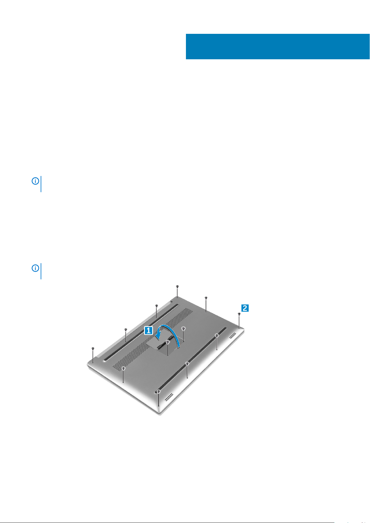
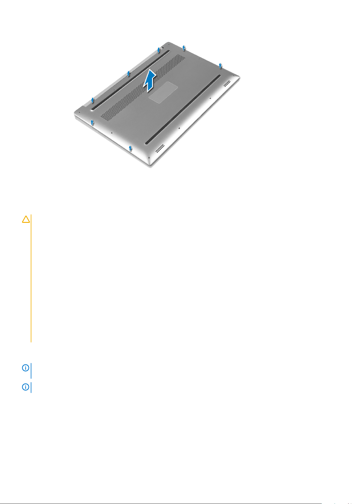
Removing the Base Cover
1. Follow the procedures in Before Working Inside Your Computer.
2. Close the display and turn the computer over.
3. Turn the system badge flap over and then remove the M2x3 T5 (10), M2x8.5 (2) screws that secure the base cover to the computer
[1,2].
NOTE:
badge flap.
Use a Torx #5 screwdriver for the base screws and a Philips screwdriver for the two M2x8.5 screws inside the
4. Pry the edges of the base cover and lift it to remove it from the computer.
14 Disassembly and reassembly
Page 15
Battery
Lithium-ion battery precautions
CAUTION:
• Exercise caution when handling Lithium-ion batteries.
• Discharge the battery as much as possible before removing it from the system. This can be done by disconnecting
the AC adapter from the system to allow the battery to drain.
• Do not crush, drop, mutilate, or penetrate the battery with foreign objects.
• Do not expose the battery to high temperatures, or disassemble battery packs and cells.
• Do not apply pressure to the surface of the battery.
• Do not bend the battery.
• Do not use tools of any kind to pry on or against the battery.
• Ensure any screws during the servicing of this product are not lost or misplaced, to prevent accidental puncture or
damage to the battery and other system components.
• If the battery gets stuck inside your computer as a result of swelling, do not try to release it as puncturing, bending,
or crushing a lithium-ion battery can be dangerous. In such an instance, contact Dell technical support for
assistance. See www.dell.com/contactdell.
• Always purchase genuine batteries from www.dell.com or authorized Dell partners and resellers.
Removing the Battery
NOTE:
the A/C adapter from the system (while the system is turned on) to allow the system to drain the battery.
NOTE: System shipped with 3-Cell battery has 4 screws, the hard drive will be part of the configuration (Optional).
1. Follow the procedures in Before Working Inside Your Computer.
2. Remove the base cover
3. Perform the following steps to remove the battery:
a) Disconnect the battery cable from the system board [1].
b) Remove the M2x4 (7) screws that secure the battery to the computer [2].
c) Lift the battery off the computer [3].
• Do not apply pressure to the surface of the battery
Discharge the battery as much as possible before removing from the system. This can be done by disconnecting
Disassembly and reassembly
15
Page 16

• Do not bend
• Do not use tools of any kind to pry on or against the battery
• If a battery cannot be removed within the constraints above, please contact Dell technical support
Installing the Battery
1. Place and align the battery in the battery bay.
2. Tighten the M2x4 (7) screws that secure the battery to the computer.
3. Connect the battery cable to the system board.
4. Install the base cover.
5. Follow the procedures in After Working Inside Your Computer.
PCIe Solid State Drive (SSD)
Removing M.2 Solid State Drive -SSD
1. Follow the procedures in Before Working Inside Your Computer
2. Remove the:
a) base cover
b) battery
3. Remove the M2x3 (1) screw that secures the M.2 solid-state drive (SSD) to the system board [1].
4. Lift the M.2 solid-state drive (SSD) from the system board [2].
16
Disassembly and reassembly
Page 17

5. Pull the SSD card thermal pad to access the bare SSD card.
Installing M.2 Solid State Drive -SSD
1. Adhere the thermal pad to the M.2 solid-state drive.
NOTE:
2. Slide the M.2 solid-state drive at an angle into the solid-state drive slot.
3. Press the other end of the solid-state drive down and replace the M2x3 (1) screw that secures the solid-state drive to the system
board.
4. Install the:
a) battery
b) base cover
5. Follow the procedures in After Working Inside Your Computer.
The thermal pad is applicable only for a PCIe SSD card.
Disassembly and reassembly
17
Page 18

Hard drive
Removing 2.5 inch Hard Drive -optional
1. Follow the procedures in Before Working Inside Your Computer.
2. Remove the:
a) base cover
b) battery
NOTE: System shipped with 3-Cell battery, the hard drive will be part of the configuration (Optional).
3. Perform the following steps to remove the hard-drive bracket from the computer:
a) Remove the M2x4 (4) screws securing the hard-drive bracket to the computer [1].
b) Lift the hard-drive cage [2] off the hard drive assembly [3].
4. Perform the following steps to remove the hard-drive:
a) Disconnect the hard-drive cable from the system board [1].
b) Lift the hard drive off the palm rest assembly [2].
5. Disconnect the hard drive interposer from the hard drive assembly and then remove the hard drive covers away from the hard drive
[1,2].
18
Disassembly and reassembly
Page 19

Installing the Hard Drive -optional
1. Replace the hard-drive covers on the hard drive.
2. Connect the hard-drive interposer to the hard-drive assembly.
3. Place the hard-drive assembly on the palm-rest assembly.
4. Connect the hard-drive cable to the system board.
5. Align the screw holes on the hard-drive cage with the screw holes on the hard-drive assembly.
6. Replace the M2x4 (4) screws that secure the hard-drive cage to the palm-rest assembly.
7. Install the:
a) battery
b) base cover
8. Follow the procedures in After Working Inside Your Computer.
Speaker
Removing the Speakers
1. Follow the procedures in Before Working Inside Your Computer.
2. Remove the:
a) base cover
b) battery
3. Perform the following steps to remove the speaker:
a) Disconnect the speaker cable from the system board [1].
b) Remove the M2x2 (4) screws that secure the speakers to the computer [2].
c) Lift the speakers, along with the speaker cable, off the computer [3].
Disassembly and reassembly
19
Page 20

Installing the Speakers
1. Using the alignment posts, place the speakers on the palm-rest assembly.
2. Replace the M2x2 (4) screws that secure the speakers to the palm-rest assembly.
3. Route the speaker cables through the routing guides on the palm-rest assembly.
4. Connect the speaker cable to the system board.
5. Install the:
a) battery
b) base cover
6. Follow the procedures in After Working Inside Your Computer.
WLAN card
Removing the WLAN Card
1. Follow the procedures in Before Working Inside Your Computer.
2. Remove the:
a) base cover
b) battery
3. Perform the following steps to remove the WLAN card:
a) Remove the captive screw to release the bracket that secures the WLAN card to the computer [1] and lift the bracket away from
the computer [2].
b) Disconnect the antenna cables from the WLAN card [3].
c) Slide and remove the WLAN card from its connector on the board [4].
20
Disassembly and reassembly
Page 21

Installing the WLAN Card
1. Align the notch on the WLAN card with the tab on the WLAN-card connector on the system board.
2. Align the bracket which secures the WLAN card to the palmrest assembly.
3. Connect the antenna cables to the WLAN card.
CAUTION:
NOTE: The color of the antenna cables is visible near the tip of the cables. The antenna-cable color scheme for the
WLAN card supported by your computer is as follows:
Table 9. Antenna-Cable Color Scheme for the WLAN Card
Connectors on the WLAN card Antenna-cable color
Main (white triangle) white
Auxiliary (black triangle) black
Multiple input, multiple output (grey triangle) Grey (optional)
4. Tighten the captive screw to secure the bracket and the WLAN card to the palmrest assembly.
5. Install the:
a) Battery
b) Base cover
6. Follow the procedures in After Working Inside Your Computer
To avoid damage to the WLAN card, do not place any cables under it.
Memory modules
Removing the Memory Modules
1. Follow the procedures in Before Working Inside Your Computer.
2. Remove the:
a) base cover
b) battery
Disassembly and reassembly
21
Page 22

3. Pry the securing clips away from the memory module until it pops-up [1]. Then, remove the memory module from its connector on the
system board [2].
Installing the Memory Modules
1. Insert the memory module into the memory socket.
2. Press the memory module down until it clicks into place.
NOTE:
3. Install the:
a) Battery
b) Base cover
4. Follow the procedures in After Working Inside Your Computer.
If you do not hear the click, remove the memory module and re-install it.
System fan
Removing the Fans
1. Follow the procedures in Before Working Inside Your Computer.
2. Remove the:
a) base cover
b) battery
3. Perform the following steps to remove the left video-card fan:
a) Release the Mylar tape that secures the cable to the system board [1].
b) Disconnect the fan cable from the system board [2]
c) Remove the M2x4 (2) screws that secure the fan to the system board [3].
d) Lift the fan away from the computer [4]
22
Disassembly and reassembly
Page 23

4. Perform the following steps to remove the right system fan:
a) Remove the M2x4 (2) screws and lift the metal bracket that holds the left video-card fan to the system board [1].
b) Lift the metal bracket that secures the DisplayPort over Type-C [2].
Disassembly and reassembly
23
Page 24

c) Disconnect the display cable from the system board [1].
d) Un-route the display cable from the restraints [2]
e) Disconnect the system fan cable from the system board [3].
f) Remove the M2x4 (2) screws that secure the system fan to the system board [4].
g) Lift the fan away from the laptop [5].
24
Disassembly and reassembly
Page 25

Installing the Fans
1. Perform the following steps to install the system fan:
a) Align the screw holes on the left fan with the screw holes on the palm-rest assembly.
b) Connect the left fan cable to the system board.
c) Route the display cable through the routing guides on the left fan.
d) Replace the M2x4 (2) screws that secure the left fan to the system board.
e) Align the right fan to the system board.
f) Route the touch-screen cable through the routing guides on the right fan.
g) Connect the touch-screen cable to the system board.
h) Connect the fan cable to the connector to the system board.
i) Replace the Mylar tape that secures the cable to the system board
j) Align the metal brackets that secure touch-screen cable and DisplayPort Over Type-C cable.
k) Replace the M2x4 (2) screws that secure the metal brackets and right fan to the system board.
a) Install the Base cover
2. Follow the procedures in After Working Inside Your Computer.
Heat sink assembly
Removing the Heatsink
1. Follow the procedures in Before Working Inside Your Computer.
2. Remove the:
CAUTION:
before you touch.
The heat sink may become hot during normal operation. Allow sufficient time for the heat sink to cool
Disassembly and reassembly 25
Page 26

NOTE: The Heatsink removal screw may vary depending upon the type of Heatsink installed.
a) base cover
b) battery
3. Remove the M2x3 (5) screws that secure the heatsink to the system board.
NOTE: Ensure to remove the screws in the order (1,2,3,4,5). See the printed image number order on the top of
heatsink.
Lift the heatsink away from the system board [2].
4.
Installing the Heatsink
1. Align the heatsink with the screw holes on the system board.
2. Replace the M2x3 (5) screws to secure the heatsink to the system board.
NOTE:
heatsink
3. Install the:
a) Battery
b) Base cover
4. Follow the procedures in After Working Inside Your Computer
Ensure to replace the screws in the order (1,2,3,4,5). See the printed image number order on the top of
Power connector port
Removing the DC-in Connector
1. Follow the procedures in Before Working Inside Your Computer.
2. Remove the:
a) base cover
b) battery
3. Perform the following steps to remove the I/O board:
a) Disconnect the DC-in cable from the connector to the system board [1].
b) Remove the M2x3 screw that secures the DC-in connector to the computer [2].
26
Disassembly and reassembly
Page 27

c) Lift the DC-in connector from the computer [3].
Installing the DC-in Adapter Port
1. Place the DC-in adapter port into the slot on the palm-rest assembly.
2. Route the power-adapter port cable through its routing guides on the palm-rest assembly.
3. Replace the M2x3 screw that secures the power-adapter port to the palm-rest assembly.
4. Connect the power-adapter port cable to the system board.
5. Install the:
a) Battery
b) Base cover
6. Follow the procedures in After Working Inside Your Computer.
System board
Removing the System Board
1. Follow the procedures in Before Working Inside Your Computer.
2. Remove the:
a) base cover
b) battery
c) fans
d) heatsink assembly
e) WLAN
f) hard drive (optional)
g) keyboard
h) SSD
i) memory modules
NOTE:
BIOS after you replace the system board.
NOTE: Before disconnecting the cables from the system board, note the location of the connectors so that you can
re-connect them correctly after you replace the system board.
3. To remove the system board:
a) Lift the latch and disconnect the touchpad cable [1].
b) Lift the latch and disconnect the keyboard controller board cable [2].
c) Disconnect the power connector port cable from the system board [3].
Your computer’s Service Tag is located under the system badge flap. You must enter the Service Tag in the
Disassembly and reassembly
27
Page 28

d) Disconnect the speaker cable from the connector from the system board [4].
e) Peel the adhesive tape and lift the latch to remove the fingerprint cable [5]
f) Lift the plastic lever and disconnect the display touchscreen cable [6]
g) Peel the adhesive tape to release the touch screen cable.
4. Perform the following steps to remove the system board from the chassis:
a) Remove the M2x4 (4) screws that secure the system board to the computer [1].
b) Lift the system board from the computer [2].
28
Disassembly and reassembly
Page 29

Installing the System Board
1. Align the system board on the computer.
2. Replace the M2x4 (4) screws that secure the system board to the palm-rest assembly.
3. Connect the power-adapter port cable, speaker cable, keyboard-control board cable, touchpad cable, and touch-screen cable to the
system board.
4. Connect the display cable to the system board.
5. Align the display-cable bracket with the screw hole on the system board and replace the screw (2).
6. Install the:
a) Memory
b) SSD
c) Keyboard
d) Heatsink assembly
e) Fans
f) Hard drive(optional)
g) WLAN card
h) Battery
i) Base cover
7. Follow the procedures in After Working Inside Your Computer.
Audio board
Removing Audio board
1. Follow the procedures in Before Working Inside Your Computer.
2. Remove the:
Disassembly and reassembly
29
Page 30

a) base cover
b) battery
c) WLAN card
d) hard drive
e) fans
f) heatsink assembly
g) memory modules
h) system board
3. Perform the following steps to remove the audio board:
a) Turn the system board over.
b) Remove the M2x3 (2) screws that secure the audio board to the system board [1].
c) Lift up the audio board [2].
Installing audio board
1. Align the audio port in the slot of the system board.
2. Replace the M2x3 (2) screws to secure the audio board to the system board.
3. Turn the system board over.
4. Install the:
a) System Board
b) Memory
c) Heatsink assembly
d) Fans
e) Hard drive
f) WLAN card
g) Battery
30
Disassembly and reassembly
Page 31

h) Base cover
5. Follow the procedures in After Working Inside Your Computer.
Coin-cell battery
Removing the Coin-Cell Battery
1. Follow the procedures in Before Working Inside Your Computer.
CAUTION: Removing the coin-cell battery re-sets the BIOS settings to default. It is recommended that you note the
BIOS settings before removing the coin-cell battery.
2. Remove the:
a) base cover
b) battery
c) WLAN card
d) hard drive
e) fans
f) heatsink assembly
g) memory modules
h) system board
3. Perform the following steps to remove the coin-cell battery:
a) Turn the system board over.
b) Disconnect the coin-cell battery cable from the system board [1].
c) Lift up the coin-cell battery [2].
Installing the Coin-Cell Battery
1. Replace the coin-cell battery in its slot in the computer.
Disassembly and reassembly
31
Page 32

2. Connect the coin-cell battery cable to the system board.
3. Turn the system board over.
4. Install the:
a) System Board
b) Memory
c) Heatsink assembly
d) Fans
e) Hard drive
f) WLAN card
g) Battery
h) Base cover
5. Follow the procedures in After Working Inside Your Computer.
Power button
Removing power button
1. Follow the procedures in Before Working Inside Your Computer.
2. Remove the:
a) base cover
b) battery
c) System board
3. Perform the following steps to remove the power button:
NOTE:
There are two power button options:
• Power button function with light indicator.
• Power button with fingerprint reader function without light indicator. (optional)
a) Remove the M1.6x3 (2) screws that secure the power button module to the system board [1].
b) Lift the power button away from the system chassis [2].
32
Disassembly and reassembly
Page 33

Installing power button
1. Align the power button into the slot on the system chassis.
2. Replace the M1.6x3 (2) screws that secure the power button to the system board.
3. Install the:
a) Battery
b) Base cover
4. Follow the procedures in After Working Inside Your Computer.
Power button with fingerprint reader -optional
Removing power button with fingerprint reader
1. Follow the procedures in Before Working Inside Your Computer.
2. Remove the:
a) base cover
b) battery
3. Perform the following steps to remove the power button:
a) Remove the M1.6x3 (2) screws that secure the power button to the system board [1].
NOTE:
• Power button function with light indicator.
• Power button with fingerprint reader function without light indicator (optional).
b) Release the Mylar tape that secures the power button board to the system chassis [2].
c) Remove the M1.6x1.5 (1) screw that secures the power button board to the system chassis [3].
d) Disconnect and release the adhesive data cable from the system chassis [4]
There are two power button options:
Disassembly and reassembly
33
Page 34

e) Lift the power button board away from the system chassis [5].
Installing power button with fingerprint reader
1. Place the power button into the slot on the system chassis.
NOTE:
• Power button function with light indicator.
• Power button with fingerprint reader function without light indicator (optional).
2. Connect the adhesive data cable to the system chassis .
3. Replace the M2x3 screw that secures the power button board to the system chassis.
4. Replace the Mylar tape that secures the power button board to the system chassis.
5. Replace the M2x4 (2) screws that secure the power button to the system board.
6. Install the:
a) Battery
b) Base cover
7. Follow the procedures in After Working Inside Your Computer.
There are two power button options:
Display Assembly
Removing the Display Assembly
1. Follow the procedures in Before Working Inside Your Computer.
34
Disassembly and reassembly
Page 35

2. Remove the:
a) base cover
b) battery
3. Perform the following steps:
a) Release the Mylar tape that secures the display cable to the system board [1].
b) Lift the latch and disconnect the display cable from the connector on the system board [2].
c) Release the Mylar tape that secures the display cable to the system board [3].
d) Remove the M2x4 (2) screws and lift the metal bracket that holds the left video-card fan to the system board [4].
e) Un-route the display cable from the restraints clips [5]
f) Disconnect the display cable from the system board [6].
4. To remove the display assembly:
a) Place the computer at the edge of a flat surface and remove the M2.5x5 (6) screws securing the display assembly to the system
chassis [1].
b) Lift the display assembly away from the system chassis [2].
Disassembly and reassembly
35
Page 36

Installing the Display Assembly
1. Place the palm-rest assembly at the edge of the table with the speakers facing away from the edge.
2. Align the screw holes on the palm-rest assembly with the screw holes on the display hinges.
3. Replace the M2.5 x 5 (6) screws that secure the display hinges to the palm-rest assembly.
4. Route thetouchscreen cable through the routing guides on the fan.
5. Connect thetouchscreen cable and display cable to the system board.
6. Replace the screw (2) that secures the display-cable bracket to the system board.
7. Install the:
a) Battery
b) Base cover
8. Follow the procedures in After Working Inside Your Computer
Antenna cover
Removing antenna
1. Follow the procedures in Before Working Inside Your Computer.
2. Remove the:
a) base cover
b) battery
c) WLAN card
d) display assembly
36
Disassembly and reassembly
Page 37

3. Gently place the system on a flat surface .
4. Rotate the hinges to angle 45° to release the antenna cable.
5. Slide and lift the antenna cover away from the display assembly.
6. To remove the antenna module:
a) Remove the copper tapes that secure the antenna module [1].
b) Remove the M2x4 (4) screws and lift the metal brackets that secure the antenna cable [2,3].
Disassembly and reassembly
37
Page 38

Installing the antenna cover
1. Replace the antenna cover on the display assembly.
2. Turn the display hinges to the normal position.
3. Install the:
a) Display assembly
b) WLAN card
c) Battery
d) Base cover
4. Follow the procedures in After Working Inside Your Computer.
Keyboard lattice and Keyboard
Removing the Keyboard
1. Follow the procedures in Before Working Inside Your Computer.
2. Remove the:
a) base cover
b) battery
c) fans
d) heatsink assembly
e) SSD
f) memory modules
g) system board
3. Perform the following steps to disconnect the keyboard and backlight connectors from the computer.
a) Lift up the latch [1] and the disconnect the cables from the connectors [2].
b) Peel back the screw shields [3].
38
Disassembly and reassembly
Page 39

4. Un-route the Keyboard cable [1] and then remove the M1.6 x 1.5 (31) screws that secure the keyboard to the computer [2].
5. Disconnect the cable from the connector on the system board.
6. Remove the screw (2) that secures the keyboard pad to the system board.
7. Lift and remove the keyboard from the system chassis.
Disassembly and reassembly
39
Page 40

Installing the Keyboard
1. Adhere the Mylar to the keyboard.
2. Align the screw holes on the keyboard with the screw holes on the palm-rest assembly.
3. Replace the M1.6 x 1.5 (31) screws that secure the keyboard to the palm-rest assembly.
4. Adhere the Mylar to the screws that secure the keyboard to the palm-rest assembly.
5. Connect the keyboard cable and keyboard-backlight cable to the keyboard-controls board.
6. Install the:
a) System Board
b) Hard drive
c) Base cover
7. Follow the procedures in After Working Inside Your Computer.
Palm rest
Removing the Palm rest Assembly
1. Follow the procedures in Before Working Inside Your Computer.
2. Remove the:
a) base cover
b) battery
c) WLAN card
d) hard drive
e) fans
f) speakers
g) heatsink assembly
40
Disassembly and reassembly
Page 41

h) memory modules
i) system board
j) display assembly
k) power connector port
l) keyboard
3. After performing the above steps, we are left with the palm rest assembly.
Disassembly and reassembly 41
Page 42

Figure 1. Power button with light indicator
Figure 2. Fingerprint reader function without light indicator
Installing the Palm rest Assembly
1. Align the palm rest assembly on the display assembly.
2. Tighten the screws to secure the display hinges to the palm rest assembly.
3. Press down on the palm rest assembly to close the display.
42
Disassembly and reassembly
Page 43

4. Install the:
a) keyboard
b) system board
c) power connector port
d) display assembly
e) fans
f) heatsink assembly
g) speakers
h) WLAN card
i) hard drive(optional)
j) memory modules
k) battery
l) base cover
5. Follow the procedures in After Working Inside Your Computer
Disassembly and reassembly 43
Page 44

4
Technology and components
This chapter details the technology and components available in the system.
Topics:
• USB Type-C
• USB features
USB Type-C
USB Type-C is a new, tiny physical connector. The connector itself can support various exciting new USB standard like USB 3.1 and USB
power delivery (USB PD).
Alternate Mode
USB Type-C is a new connector standard that's very small. It's about a third the size of an old USB Type-A plug. This is a single connector
standard that every device should be able to use. USB Type-C ports can support a variety of different protocols using “alternate modes,”
which allows you to have adapters that can output HDMI, VGA, DisplayPort, or other types of connections from that single USB port
USB Power Delivery
The USB PD specification is also closely intertwined with USB Type-C. Currently, smartphones, tablets, and other mobile devices often
use a USB connection to charge. A USB 2.0 connection provides up to 2.5 watts of power — that'll charge your phone, but that's about
it. A laptop might require up to 60 watts, for example. The USB Power Delivery specification ups this power delivery to 100 watts. It's bidirectional, so a device can either send or receive power. And this power can be transferred at the same time the device is transmitting
data across the connection.
This could spell the end of all those proprietary laptop charging cables, with everything charging via a standard USB connection. You could
charge your laptop from one of those portable battery packs you charge your smartphones and other portable devices from today. You
could plug your laptop into an external display connected to a power cable, and that external display would charge your laptop as you used
it as an external display — all via the one little USB Type-C connection. To use this, the device and the cable have to support USB Power
Delivery. Just having a USB Type-C connection doesn't necessarily mean they do.
USB Type-C and USB 3.1
USB 3.1 is a new USB standard. USB 3's theoretical bandwidth is 5 Gbps, while USB 3.1 Gen2 is10Gbps . That's double the bandwidth, as
fast as a first-generation Thunderbolt connector. USB Type-C isn't the same thing as USB 3.1. USB Type-C is just a connector shape, and
the underlying technology could just be USB 2 or USB 3.0. In fact, Nokia's N1 Android tablet uses a USB Type-C connector, but
underneath it's all USB 2.0 — not even USB 3.0. However, these technologies are closely related.
USB features
Universal Serial Bus, or USB, was introduced in 1996. It dramatically simplified the connection between host computers and peripheral
devices like mice, keyboards, external drivers, and printers.
Let's take a quick look on the USB evolution referencing to the table below.
Table 10. USB evolution
Type Data Transfer Rate Category Introduction Year
USB 2.0 480 Mbps High Speed 2000
USB 3.0/USB 3.1 Gen
1Port
44 Technology and components
5 Gbps Super Speed 2010
Page 45

Type Data Transfer Rate Category Introduction Year
USB 3.1 Gen 2 10 Gbps Super Speed 2013
USB 3.0/USB 3.1 Gen 1 (SuperSpeed USB)
For years, the USB 2.0 has been firmly entrenched as the de facto interface standard in the PC world with about 6 billion devices sold, and
yet the need for more speed grows by ever faster computing hardware and ever greater bandwidth demands. The USB 3.0/USB 3.1 Gen 1
finally has the answer to the consumers' demands with a theoretically 10 times faster than its predecessor. In a nutshell, USB 3.1 Gen 1
features are as follows:
• Higher transfer rates (up to 5 Gbps)
• Increased maximum bus power and increased device current draw to better accommodate power-hungry devices
• New power management features
• Full-duplex data transfers and support for new transfer types
• Backward USB 2.0 compatibility
• New connectors and cable
The topics below cover some of the most commonly asked questions regarding USB 3.0/USB 3.1 Gen 1.
Speed
Currently, there are 3 speed modes defined by the latest USB 3.0/USB 3.1 Gen 1 specification. They are Super-Speed, Hi-Speed and FullSpeed. The new SuperSpeed mode has a transfer rate of 4.8Gbps. While the specification retains Hi-Speed, and Full-Speed USB mode,
commonly known as USB 2.0 and 1.1 respectively, the slower modes still operate at 480Mbps and 12Mbps respectively and are kept to
maintain backward compatibility.
USB 3.0/USB 3.1 Gen 1 achieves the much higher performance by the technical changes below:
• An additional physical bus that is added in parallel with the existing USB 2.0 bus (refer to the picture below).
• USB 2.0 previously had four wires (power, ground, and a pair for differential data); USB 3.0/USB 3.1 Gen 1 adds four more for two
pairs of differential signals (receive and transmit) for a combined total of eight connections in the connectors and cabling.
• USB 3.0/USB 3.1 Gen 1 utilizes the bidirectional data interface, rather than USB 2.0's half-duplex arrangement. This gives a 10-fold
increase in theoretical bandwidth.
With today's ever increasing demands placed on data transfers with high-definition video content, terabyte storage devices, high
megapixel count digital cameras etc., USB 2.0 may not be fast enough. Furthermore, no USB 2.0 connection could ever come close to the
480Mbps theoretical maximum throughput, making data transfer at around 320Mbps (40MB/s) — the actual real-world maximum.
Similarly, USB 3.0/USB 3.1 Gen 1 connections will never achieve 4.8Gbps. We will likely see a real-world maximum rate of 400MB/s with
overheads. At this speed, USB 3.0/USB 3.1 Gen 1 is a 10x improvement over USB 2.0.
Technology and components
45
Page 46

Applications
USB 3.0/USB 3.1 Gen 1 opens up the laneways and provides more headroom for devices to deliver a better overall experience. Where USB
video was barely tolerable previously (both from a maximum resolution, latency, and video compression perspective), it's easy to imagine
that with 5-10 times the bandwidth available, USB video solutions should work that much better. Single-link DVI requires almost 2Gbps
throughput. Where 480Mbps was limiting, 5Gbps is more than promising. With its promised 4.8Gbps speed, the standard will find its way
into some products that previously weren't USB territory, like external RAID storage systems.
Listed below are some of the available SuperSpeed USB 3.0/USB 3.1 Gen 1 products:
• External Desktop USB 3.0/USB 3.1 Gen 1 Hard Drives
• Portable USB 3.0/USB 3.1 Gen 1 Hard Drives
• USB 3.0/USB 3.1 Gen 1 Drive Docks & Adapters
• USB 3.0/USB 3.1 Gen 1 Flash Drives & Readers
• USB 3.0/USB 3.1 Gen 1 Solid-state Drives
• USB 3.0/USB 3.1 Gen 1 RAIDs
• Optical Media Drives
• Multimedia Devices
• Networking
• USB 3.0/USB 3.1 Gen 1 Adapter Cards & Hubs
Compatibility
The good news is that USB 3.0/USB 3.1 Gen 1 has been carefully planned from the start to peacefully co-exist with USB 2.0. First of all,
while USB 3.0/USB 3.1 Gen 1 specifies new physical connections and thus new cables to take advantage of the higher speed capability of
the new protocol, the connector itself remains the same rectangular shape with the four USB 2.0 contacts in the exact same location as
before. Five new connections to carry receive and transmitted data independently are present on USB 3.0/USB 3.1 Gen 1 cables and only
come into contact when connected to a proper SuperSpeed USB connection.
46
Technology and components
Page 47

5
Troubleshooting
Enhanced Pre-Boot System Assessment — ePSA diagnostics
The ePSA diagnostics (also known as system diagnostics) performs a complete check of your hardware. The ePSA is embedded with the
BIOS and is launched by the BIOS internally. The embedded system diagnostics provides a set of options for particular devices or device
groups allowing you to:
The ePSA diagnostics can be initiated by the FN+PWR buttons while powering on the computer.
• Run tests automatically or in an interactive mode
• Repeat tests
• Display or save test results
• Run thorough tests to introduce additional test options to provide extra information about the failed device(s)
• View status messages that inform you if tests are completed successfully
• View error messages that inform you of problems encountered during testing
NOTE:
terminal when the diagnostic tests are performed.
Some tests for specific devices require user interaction. Always ensure that you are present at the computer
Running the ePSA Diagnostics
Invoke diagnostics boot by either of the methods that are suggested below:
1. Power on the computer.
2. As the computer boots, press the F12 key when the Dell logo is displayed.
3. In the boot menu screen, use Up/Down arrow key to select the Diagnostics option and then press Enter.
NOTE:
The diagnostics starts running the tests on all the detected devices.
4. Press the arrow in the lower-right corner to go to the page listing.
The detected items are listed and tested.
5. To run a diagnostic test on a specific device, press Esc and click Yes to stop the diagnostic test.
6. Select the device from the left pane and click Run Tests.
7. If there are any issues, error codes are displayed.
Note the error code and contact Dell.
or
8. Shut down the computer.
9. Press and hold the Fn key, while pressing the power button, and then release both.
10. Repeat steps 3–7 above.
The Enhanced Pre-boot System Assessment window displays, listing all devices detected in the computer.
Troubleshooting 47
Page 48

6
Getting help
Topics:
• Contacting Dell
Contacting Dell
NOTE: If you do not have an active Internet connection, you can find contact information on your purchase invoice,
packing slip, bill, or Dell product catalog.
Dell provides several online and telephone-based support and service options. Availability varies by country and product, and some services
may not be available in your area. To contact Dell for sales, technical support, or customer service issues:
1. Go to Dell.com/support.
2. Select your support category.
3. Verify your country or region in the Choose a Country/Region drop-down list at the bottom of the page.
4. Select the appropriate service or support link based on your need.
48 Getting help
 Loading...