


Precision 5530
Service Manual
Regulatory Model: P56F
Regulatory Type: P56F002

Notes, cautions, and warnings
NOTE: A NOTE indicates important information that helps you make better use of your product.
CAUTION: A CAUTION indicates either potential damage to hardware or loss of data and tells you how to avoid the problem.
WARNING: A WARNING indicates a potential for property damage, personal injury, or death.
© 2018 Dell Inc. or its subsidiaries. All rights reserved. Dell, EMC, and other trademarks are trademarks of Dell Inc. or its subsidiaries. Other trademarks
may be trademarks of their respective owners.
2018 - 04
Rev. A00

Working on your computer
Safety instructions
Use the following safety guidelines to protect your computer from potential damage and to ensure your personal safety. Unless otherwise
noted, each procedure included in this document assumes that the following conditions exist:
• You have read the safety information that shipped with your computer.
• A component can be replaced or, if purchased separately, installed by performing the removal procedure in reverse order.
WARNING: Disconnect all power sources before opening the computer cover or panels. After you nish working inside the
computer, replace all covers, panels, and screws before connecting to the power source.
WARNING: Before working inside your computer, read the safety information that shipped with your computer. For additional
safety best practices information, see the Regulatory Compliance Homepage at www.Dell.com/regulatory_compliance
CAUTION: Many repairs may only be done by a certied service technician. You should only perform troubleshooting and simple
repairs as authorized in your product documentation, or as directed by the online or telephone service and support team.
Damage due to servicing that is not authorized by Dell is not covered by your warranty. Read and follow the safety instructions
that came with the product.
CAUTION: To avoid electrostatic discharge, ground yourself by using a wrist grounding strap or by periodically touching an
unpainted metal surface at the same time as touching a connector on the back of the computer.
CAUTION: Handle components and cards with care. Do not touch the components or contacts on a card. Hold a card by its
edges or by its metal mounting bracket. Hold a component such as a processor by its edges, not by its pins.
CAUTION: When you disconnect a cable, pull on its connector or on its pull-tab, not on the cable itself. Some cables have
connectors with locking tabs; if you are disconnecting this type of cable, press in on the locking tabs before you disconnect the
cable. As you pull connectors apart, keep them evenly aligned to avoid bending any connector pins. Also, before you connect a
cable, ensure that both connectors are correctly oriented and aligned.
NOTE: The color of your computer and certain components may appear dierently than shown in this document.
1
CAUTION: System will shut down if side covers are removed while the system is running. The system will not power on if the side
cover is removed.
CAUTION: System will shut down if side covers are removed while the system is running. The system will not power on if the side
cover is removed.
CAUTION: System will shut down if side covers are removed while the system is running. The system will not power on if the side
cover is removed.
Turning o your computer — Windows 10
CAUTION
remove the side cover.
1
Click or tap .
2 Click or tap and then click or tap Shut down.
: To avoid losing data, save and close all open les and exit all open programs before you turn o your computer or
: Ensure that the computer and all attached devices are turned o. If your computer and attached devices did not
NOTE
automatically turn o when you shut down your operating system, press and hold the power button for about 6 seconds to
turn them o.
Working on your computer 3

Before working inside your computer
1 Ensure that your work surface is at and clean to prevent the computer cover from being scratched.
2 Turn o your computer.
3 If the computer is connected to a docking device (docked), undock it.
4 Disconnect all network cables from the computer (if available).
CAUTION: If your computer has an RJ45 port, disconnect the network cable by rst unplugging the cable from your
computer.
5 Disconnect your computer and all attached devices from their electrical outlets.
6 Open the display.
7 Press and hold the power button for few seconds, to ground the system board.
CAUTION: To guard against electrical shock unplug your computer from the electrical outlet before performing Step # 8.
CAUTION: To avoid electrostatic discharge, ground yourself by using a wrist grounding strap or by periodically touching an
unpainted metal surface at the same time as touching a connector on the back of the computer.
8 Remove any installed ExpressCards or Smart Cards from the appropriate slots.
After working inside your computer
After you complete any replacement procedure, ensure that you connect any external devices, cards, and cables before turning on your
computer.
CAUTION
designed for other Dell computers.
1 Replace the battery.
2 Replace the base cover.
3 Connect any external devices, such as a port replicator or media base, and replace any cards, such as an ExpressCard.
4 Connect any telephone or network cables to your computer.
5 Connect your computer and all attached devices to their electrical outlets.
6 Turn on your computer.
: To avoid damage to the computer, use only the battery designed for this particular Dell computer. Do not use batteries
CAUTION
computer.
: To connect a network cable, rst plug the cable into the network device and then plug it into the
4
Working on your computer

Technology and components
This chapter details the technology and components available in the system.
Topics:
• Processors
• Chipset
• Memory features
• Display
• Hard drive
• USB features
• HDMI 1.4- HDMI 2.0
Processors
The Precision 5530 is shipped with Intel 8th generation core processor technology. Processors supported on this platform are:
2
8th Generation:
Intel Core i9 (6-core 2.9GHz, 4.8GHz Turbo, 12MB 45W, w/ Intel UHD Graphics 630)
Intel Core i7 (6-core 2.6GHz, 4.3GHz Turbo, 9MB 45W, w/ Intel UHD Graphics 630)
Intel Core i5 (4-core 2.3GHz, 4.0GHz Turbo, 8MB 45W, w/ Intel UHD Graphics 630)
Intel Xeon E-2176M (6-core 2.7GHz, 4.4GHz Turbo, 12MB 45W, w/ Intel UHD Graphics P630)
: The clock speed and performance varies depending on the workload and other variables.
NOTE
Chipset
The chipset is Intel CM246.
Identifying chipset in device manager on Windows 10
: The Chipset information displayed is a generic image and may be dierent from what is displayed.
NOTE
1 Type Device Manager in the Ask me anything eld.
Device Manager window appears.
2 Expand System Devices and search for the chipset.
Technology and components 5

Memory features
The Precision 5530 supports the following memory congurations:
• 32 GB 2666 MHz DDR4—2x16G
• 16 GB 2666 MHz DDR4—1x16G
• 16 GB 2666 MHz DDR4—2x8G
• 8 GB 2666 MHz DDR4—1x8G
• 8 GB 2666 MHz DDR4—2x4G
Verifying system memory
Windows 10
1 Click the Windows button and select All Settings > System .
2 Under System, click About.
Verifying system memory in setup
1 Turn on or restart your tabletnotebookdesktop.
2 When the Dell logo appears, press F2.
Entering BIOS setup message appears.
3 On the left pane, select Settings > General > System Information,
The memory information is displayed on the right pane.
Technology and components
6

Testing memory using ePSA
1 Turn on or restart your computer.
2 Press F12 or press Fn+PWR to invoke the ePSA diagnostics.
The PreBoot System Assessment (PSA) starts on your computer.
NOTE: If you wait too long and the operating system logo appears, continue to wait until you see the login screen/desktop
screen. Turn o the computer and try again.
If the memory test results in 25 or less errors, then the RMT basic feature automatically xes the issues. The test will indicate a pass result
since the defect(s) have been removed. If the memory test results in 26 - 50 errors, the RMT basic feature masks the defective memory
blocks and results in pass with no memory replacement requirement. If the memory test results in more than 50 errors, then the test is
stalled and the result indicates that memory module replacement is required.
Display
Display section details on identifying the display adapter from the display manager along with steps on how change the screen resolution. It
also contains information about connecting multiple monitors.
Identifying display adapter
1 Type Device manager in the Ask me anything eld.
The Display Manager window is displayed.
2 Expand the Display adapters.
The display adapter information is displayed.
Figure 1. display adapter
Changing the screen resolution
1 Right click on the desktop and select Display Settings.
2 Tap or click the Advanced display settings.
3 Select the required resolution from the drop-down list and tap Apply.
Technology and components
7

Connecting to external display devices
Follow these steps to connect your computer to an external display device:
1 Ensure that the projector is turned on and plug the projector cable into a video port on your computer.
2 Press the Windows logo+P key.
3 Select one of the following modes:
• PC screen only
• Duplicate
• Extend
• Second Screen only
NOTE
: For more information, see the document that is shipped with your display device.
Hard drive
This section explains how to identify the hard drive type installed in the system.
Identifying storage device in Windows 10
1 Type Device Manager in I'm Cortana, Ask me anything eld.
The Device Manager window is displayed.
2 Click Disk Drives.
The storage devices installed in the system are displayed.
USB features
Universal Serial Bus, or USB, was introduced in 1996. It dramatically simplied the connection between host computers and peripheral
devices like mice, keyboards, external drivers, and printers.
Let's take a quick look on the USB evolution referencing to the table below.
Technology and components
8

Table 1. USB evolution
Type Data Transfer Rate Category Introduction Year
USB 3.0/USB 3.1 Gen
1Port
USB 2.0 480 Mbps High Speed 2000
USB 3.1 Gen 2 10 Gbps Super Speed 2013
5 Gbps Super Speed 2010
USB 3.0/USB 3.1 Gen 1 (SuperSpeed USB)
For years, the USB 2.0 has been rmly entrenched as the de facto interface standard in the PC world with about 6 billion devices sold, and
yet the need for more speed grows by ever faster computing hardware and ever greater bandwidth demands. The USB 3.0/USB 3.1 Gen 1
nally has the answer to the consumers' demands with a theoretically 10 times faster than its predecessor. In a nutshell, USB 3.1 Gen 1
features are as follows:
• Higher transfer rates (up to 5 Gbps)
• Increased maximum bus power and increased device current draw to better accommodate power-hungry devices
• New power management features
• Full-duplex data transfers and support for new transfer types
• Backward USB 2.0 compatibility
• New connectors and cable
The topics below cover some of the most commonly asked questions regarding USB 3.0/USB 3.1 Gen 1.
Speed
Currently, there are 3 speed modes dened by the latest USB 3.0/USB 3.1 Gen 1 specication. They are Super-Speed, Hi-Speed and FullSpeed. The new SuperSpeed mode has a transfer rate of 4.8Gbps. While the specication retains Hi-Speed, and Full-Speed USB mode,
commonly known as USB 2.0 and 1.1 respectively, the slower modes still operate at 480Mbps and 12Mbps respectively and are kept to
maintain backward compatibility.
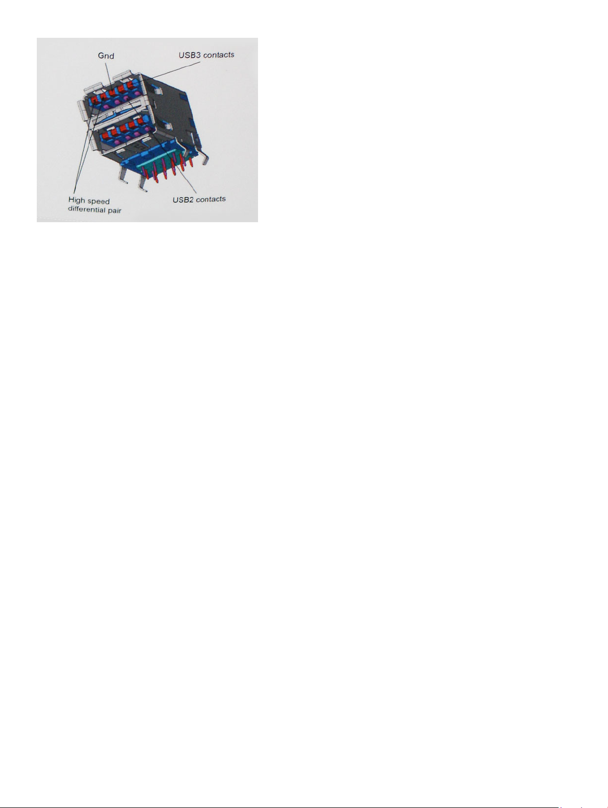
USB 3.0/USB 3.1 Gen 1 achieves the much higher performance by the technical changes below:
• An additional physical bus that is added in parallel with the existing USB 2.0 bus (refer to the picture below).
• USB 2.0 previously had four wires (power, ground, and a pair for dierential data); USB 3.0/USB 3.1 Gen 1 adds four more for two pairs
of dierential signals (receive and transmit) for a combined total of eight connections in the connectors and cabling.
• USB 3.0/USB 3.1 Gen 1 utilizes the bidirectional data interface, rather than USB 2.0's half-duplex arrangement. This gives a 10-fold
increase in theoretical bandwidth.
Technology and components
9
With today's ever increasing demands placed on data transfers with high-denition video content, terabyte storage devices, high megapixel
count digital cameras etc., USB 2.0 may not be fast enough. Furthermore, no USB 2.0 connection could ever come close to the 480Mbps
theoretical maximum throughput, making data transfer at around 320Mbps (40MB/s) — the actual real-world maximum. Similarly, USB
3.0/USB 3.1 Gen 1 connections will never achieve 4.8Gbps. We will likely see a real-world maximum rate of 400MB/s with overheads. At this
speed, USB 3.0/USB 3.1 Gen 1 is a 10x improvement over USB 2.0.
Applications
USB 3.0/USB 3.1 Gen 1 opens up the laneways and provides more headroom for devices to deliver a better overall experience. Where USB
video was barely tolerable previously (both from a maximum resolution, latency, and video compression perspective), it's easy to imagine
that with 5-10 times the bandwidth available, USB video solutions should work that much better. Single-link DVI requires almost 2Gbps
throughput. Where 480Mbps was limiting, 5Gbps is more than promising. With its promised 4.8Gbps speed, the standard will nd its way
into some products that previously weren't USB territory, like external RAID storage systems.
Listed below are some of the available SuperSpeed USB 3.0/USB 3.1 Gen 1 products:
• External Desktop USB 3.0/USB 3.1 Gen 1 Hard Drives
• Portable USB 3.0/USB 3.1 Gen 1 Hard Drives
• USB 3.0/USB 3.1 Gen 1 Drive Docks & Adapters
• USB 3.0/USB 3.1 Gen 1 Flash Drives & Readers
• USB 3.0/USB 3.1 Gen 1 Solid-state Drives
• USB 3.0/USB 3.1 Gen 1 RAIDs
• Optical Media Drives
• Multimedia Devices
• Networking
• USB 3.0/USB 3.1 Gen 1 Adapter Cards & Hubs
Compatibility
The good news is that USB 3.0/USB 3.1 Gen 1 has been carefully planned from the start to peacefully co-exist with USB 2.0. First of all,
while USB 3.0/USB 3.1 Gen 1 species new physical connections and thus new cables to take advantage of the higher speed capability of
the new protocol, the connector itself remains the same rectangular shape with the four USB 2.0 contacts in the exact same location as
before. Five new connections to carry receive and transmitted data independently are present on USB 3.0/USB 3.1 Gen 1 cables and only
come into contact when connected to a proper SuperSpeed USB connection.
Windows 8/10 will be bringing native support for USB 3.1 Gen 1 controllers. This is in contrast to previous versions of Windows, which
continue to require separate drivers for USB 3.0/USB 3.1 Gen 1 controllers.
Technology and components
10

Microsoft announced that Windows 7 would have USB 3.1 Gen 1 support, perhaps not on its immediate release, but in a subsequent Service
Pack or update. It is not out of the question to think that following a successful release of USB 3.0/USB 3.1 Gen 1 support in Windows 7,
SuperSpeed support would trickle down to Vista. Microsoft has conrmed this by stating that most of their partners share the opinion that
Vista should also support USB 3.0/USB 3.1 Gen 1.
HDMI 1.4- HDMI 2.0
This topic explains the HDMI 1.4/2.0 and its features along with the advantages.
HDMI (High-Denition Multimedia Interface) is an industry-supported, uncompressed, all-digital audio/video interface. HDMI provides an
interface between any compatible digital audio/video source, such as a DVD player, or A/V receiver and a compatible digital audio and/or
video monitor, such as a digital TV (DTV). The intended applications for HDMI TVs, and DVD players. The primary advantage is cable
reduction and content protection provisions. HDMI supports standard, enhanced, or high-denition video, plus multichannel digital audio on
a single cable.
NOTE: The HDMI 1.4 will provide 5.1 channel audio support.
HDMI 1.4- HDMI 2.0 Features
• HDMI Ethernet Channel - Adds high-speed networking to an HDMI link, allowing users to take full advantage of their IP-enabled
devices without a separate Ethernet cable
• Audio Return Channel - Allows an HDMI-connected TV with a built-in tuner to send audio data "upstream" to a surround audio system,
eliminating the need for a separate audio cable
• 3D - Denes input/output protocols for major 3D video formats, paving the way for true 3D gaming and 3D home theater applications
• Content Type - Real-time signaling of content types between display and source devices, enabling a TV to optimize picture settings
based on content type
• Additional Color Spaces - Adds support for additional color models used in digital photography and computer graphics
• 4K Support - Enables video resolutions far beyond 1080p, supporting next-generation displays that will rival the Digital Cinema systems
used in many commercial movie theaters
• HDMI Micro Connector - A new, smaller connector for phones and other portable devices, supporting video resolutions up to 1080p
• Automotive Connection System - New cables and connectors for automotive video systems, designed to meet the unique demands of
the motoring environment while delivering true HD quality
Advantages of HDMI
• Quality HDMI transfers uncompressed digital audio and video for the highest, crispest image quality.
• Low -cost HDMI provides the quality and functionality of a digital interface while also supporting uncompressed video formats in a
simple, cost-eective manner
• Audio HDMI supports multiple audio formats from standard stereo to multichannel surround sound
• HDMI combines video and multichannel audio into a single cable, eliminating the cost, complexity, and confusion of multiple cables
currently used in A/V systems
• HDMI supports communication between the video source (such as a DVD player) and the DTV, enabling new functionality
Technology and components
11
Disassembly and reassembly
Base cover
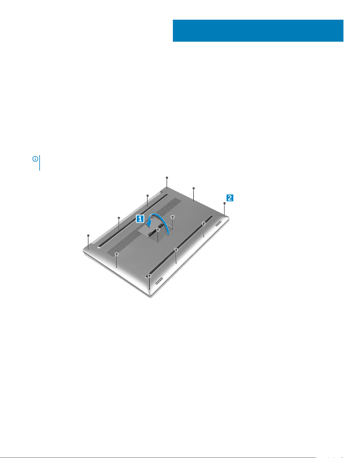
Removing the Base Cover
1 Follow the procedures in Before Working Inside Your Computer.
2 Close the display and turn the computer over.
3 Turn the system badge ap over and then remove the M2x3 T5 (10), M2x8 (2) screws that secure the base cover to the computer
[1,2].
NOTE: Use a Torx #5 screwdriver for the base screws and a Philips screwdriver for the two M2x8 screws inside the badge
ap.
3
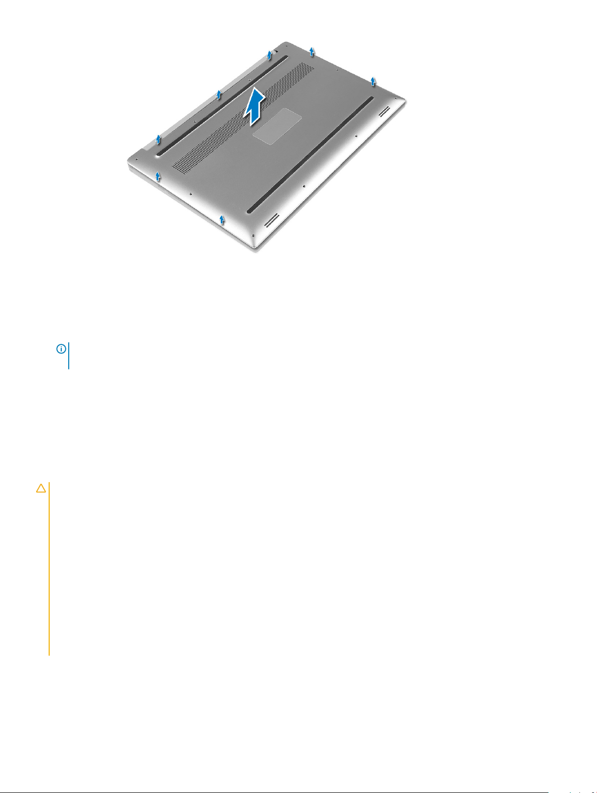
4 Pry the edges of the base cover and lift it to remove it from the computer.
12 Disassembly and reassembly
Installing the Base Cover
1 Place the base cover on the computer and snap it in place.
2 Tighten the M2x3 T5 (10), M2x8 (2) screws to secure the base cover to the computer.
NOTE
: Ensure you use a Torx #5 screwdriver for the base screws and a Philips screwdriver for the two M2x8 system badge
screws.
3 Turn the system badge ap over and snap it in place.
4 Follow the procedures in After Working Inside Your Computer.
Battery
Lithium-ion battery precautions
CAUTION
• Exercise caution when handling Lithium-ion batteries.
• Discharge the battery as much as possible before removing it from the system. This can be done by disconnecting the AC adapter
• Do not crush, drop, mutilate, or penetrate the battery with foreign objects.
• Do not expose the battery to high temperatures, or disassemble battery packs and cells.
• Do not apply pressure to the surface of the battery.
• Do not bend the battery.
• Do not use tools of any kind to pry on or against the battery.
• If a battery gets stuck in a device as a result of swelling, do not try to free it as puncturing, bending, or crushing a Lithium-ion
• Always purchase genuine batteries from https://www.dell.com or authorized Dell partners and re-sellers.
:
from the system to allow the battery to drain.
battery can be dangerous. In such an instance, the entire system should be replaced. Contact https://www.dell.com/support for
assistance and further instructions.
Disassembly and reassembly 13
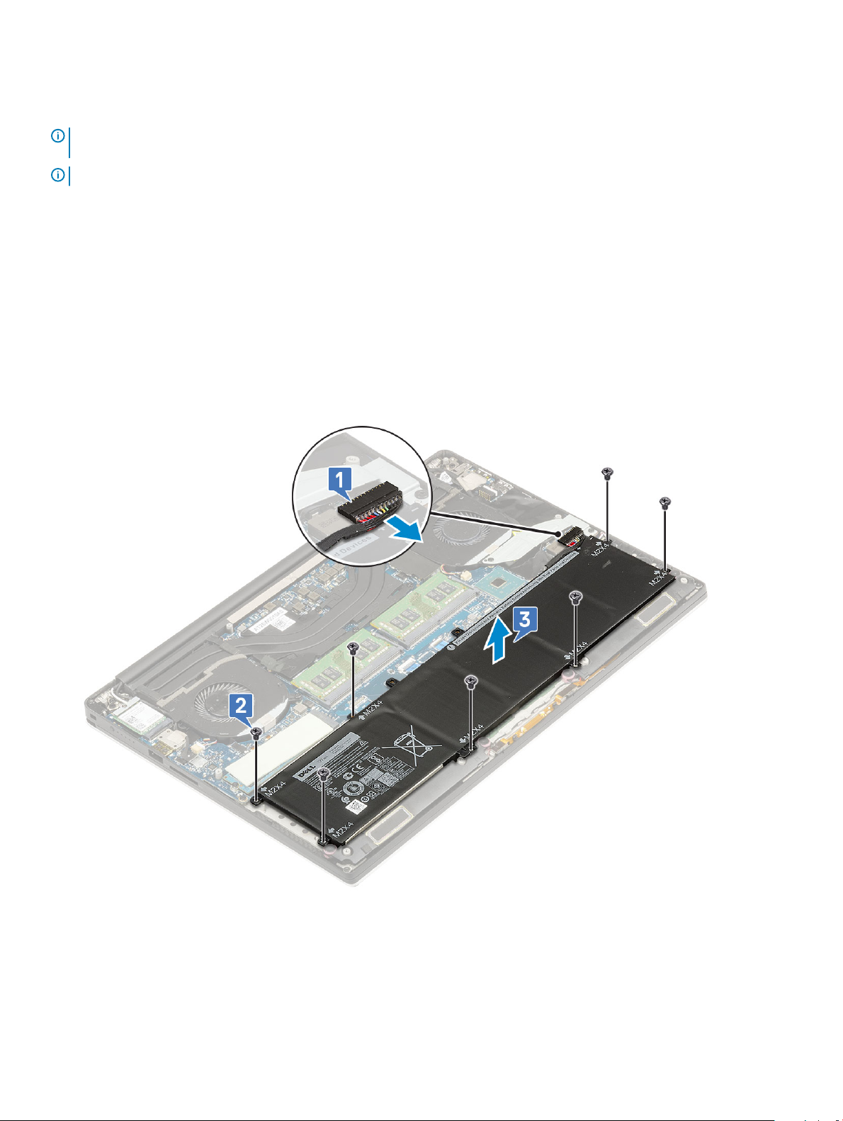
Removing the Battery
NOTE: Discharge the battery as much as possible before removing from the system. This can be done by disconnecting the A/C
adapter from the system (while the system is turned on) to allow the system to drain the battery.
NOTE: System shipped with 3-Cell battery has 4 screws, the hard drive will be part of the conguration (Optional).
1 Follow the procedures in Before Working Inside Your Computer.
2 Remove the base cover
3 Perform the following steps to remove the battery:
a Disconnect the battery cable from the system board [1].
b Remove the M2x4 (7) screws that secure the battery to the computer [2].
c Lift the battery o the computer [3].
• Do not apply pressure to the surface of the battery
• Do not bend
• Do not use tools of any kind to pry on or against the battery
• If a battery cannot be removed within the constraints above, please contact Dell technical support
Installing the Battery
1 Place and align the battery in the battery bay.
2 Tighten the M2x4 (7) screws that secure the battery to the computer.
Disassembly and reassembly
14
 Loading...