


Dell Precision 5520
Owner's Manual
Regulatory Model: P56F
Regulatory Type: P56F001

Notes, cautions, and warnings
NOTE: A NOTE indicates important information that helps you make better use of your product.
CAUTION: A CAUTION indicates either potential damage to hardware or loss of data and tells you how to avoid the
problem.
WARNING: A WARNING indicates a potential for property damage, personal injury, or death.
© 2019 Dell Inc. or its subsidiaries. All rights reserved. Dell, EMC, and other trademarks are trademarks of Dell Inc. or its subsidiaries.
Other trademarks may be trademarks of their respective owners.
2019 - 05
Rev. A02

Contents
1 Working on your computer............................................................................................................ 5
Turning off Your Computer.................................................................................................................................................. 5
Before working inside your computer................................................................................................................................. 5
After working inside your computer....................................................................................................................................5
2 Chassis........................................................................................................................................7
System Overview...................................................................................................................................................................7
Hot key combinations............................................................................................................................................................9
3 Disassembly and reassembly........................................................................................................ 11
Recommended Tools............................................................................................................................................................11
Base cover............................................................................................................................................................................. 11
Removing the Base Cover............................................................................................................................................. 11
Installing the Base Cover...............................................................................................................................................12
Battery...................................................................................................................................................................................12
Lithium-ion battery precautions................................................................................................................................... 12
Removing the Battery....................................................................................................................................................13
Installing the Battery...................................................................................................................................................... 13
PCIe Solid State Drive (SSD)............................................................................................................................................. 13
Removing the Solid State Drive (SSD)........................................................................................................................13
Installing the solid-state drive....................................................................................................................................... 14
Hard drive..............................................................................................................................................................................14
Removing the Hard Drive.............................................................................................................................................. 14
Installing the Hard Drive................................................................................................................................................ 16
Speaker..................................................................................................................................................................................16
Removing the Speakers ........................................................................................................................................... 16
Installing the Speakers................................................................................................................................................... 17
Coin-cell battery................................................................................................................................................................... 17
Removing the Coin-Cell Battery...................................................................................................................................17
Installing the Coin-Cell Battery..................................................................................................................................... 18
Keyboard lattice and Keyboard.......................................................................................................................................... 18
Removing the Keyboard................................................................................................................................................ 18
Installing the Keyboard..................................................................................................................................................20
WLAN card...........................................................................................................................................................................20
Removing the WLAN Card...........................................................................................................................................20
Installing the WLAN Card.............................................................................................................................................. 21
Memory modules..................................................................................................................................................................21
Removing the Memory Module(s)............................................................................................................................... 21
Installing the Memory Module(s).................................................................................................................................22
System fan........................................................................................................................................................................... 22
Removing the Fans .......................................................................................................................................................22
Installing the Fans.......................................................................................................................................................... 23
Heat sink ..............................................................................................................................................................................24
Removing the Heatsink.................................................................................................................................................24
Contents 3

Installing the Heatsink................................................................................................................................................... 25
Power connector port........................................................................................................................................................ 25
Removing the DC-in Connector.................................................................................................................................. 25
Installing the DC-in Adapter Port................................................................................................................................ 26
Antenna cover......................................................................................................................................................................26
Removing the antenna cover.......................................................................................................................................26
Installing the antenna cover..........................................................................................................................................27
Display Assembly................................................................................................................................................................. 28
Removing the Display Assembly.................................................................................................................................. 28
Installing the Display Assembly.....................................................................................................................................29
System board.......................................................................................................................................................................29
Removing the System Board....................................................................................................................................... 29
Installing the System Board...........................................................................................................................................31
Palm rest............................................................................................................................................................................... 31
Removing the Palmrest Assembly................................................................................................................................31
Installing the Palm rest Assembly................................................................................................................................ 32
4 Diagnostics................................................................................................................................ 33
Enhanced Pre-Boot System Assessment — ePSA diagnostics................................................................................... 33
Device Status Lights........................................................................................................................................................... 33
5 System Setup Options................................................................................................................35
6 Technical Specifications............................................................................................................. 39
7 Contacting Dell.......................................................................................................................... 44
4
Contents
Working on your computer
Turning off Your Computer
CAUTION: To avoid losing data, save and close all open files and exit all open programs before you turn off your
computer.
You can turn off your computer in two ways :
1. Using the power button
2. Using the charms menu
Using power button
1. Press and hold the Power button to turn off the screen.
Using charms
1. Swipe from the right edge of the display to access the Charms menu.
1
2. Touch Settings —> Power —> Shut down to turn off the computer.
Before working inside your computer
1. Ensure that your work surface is flat and clean to prevent the computer cover from being scratched.
2. Turn off your computer.
3. Disconnect all network cables from the computer (if available).
CAUTION:
computer.
4. Disconnect your computer and all attached devices from their electrical outlets.
5. Open the display.
6. Press and hold the power button for few seconds, to ground the system board.
CAUTION:
# 8.
CAUTION: To avoid electrostatic discharge, ground yourself by using a wrist grounding strap or by periodically
touching an unpainted metal surface at the same time as touching a connector on the back of the computer.
7. Remove any installed ExpressCards or Smart Cards from the appropriate slots.
If your computer has an RJ45 port, disconnect the network cable by first unplugging the cable from your
To guard against electrical shock unplug your computer from the electrical outlet before performing Step
After working inside your computer
After you complete any replacement procedure, ensure you connect any external devices, cards, and cables before turning on your
computer.
CAUTION:
batteries designed for other Dell computers.
1. Connect any external devices, such as a port replicator, battery slice, or media base, and replace any cards, such as an ExpressCard.
2. Connect any telephone or network cables to your computer.
To avoid damage to the computer, use only the battery designed for this particular Dell computer. Do not use
Working on your computer 5

CAUTION: To connect a network cable, first plug the cable into the network device and then plug it into the
computer.
3. Replace the battery.
4. Connect your computer and all attached devices to their electrical outlets.
5. Turn on your computer.
6 Working on your computer
Chassis
This chapter illustrates the multiple chassis views along with the ports and connectors and also explains the FN hot key combinations.
Topics:
• System Overview
• Hot key combinations
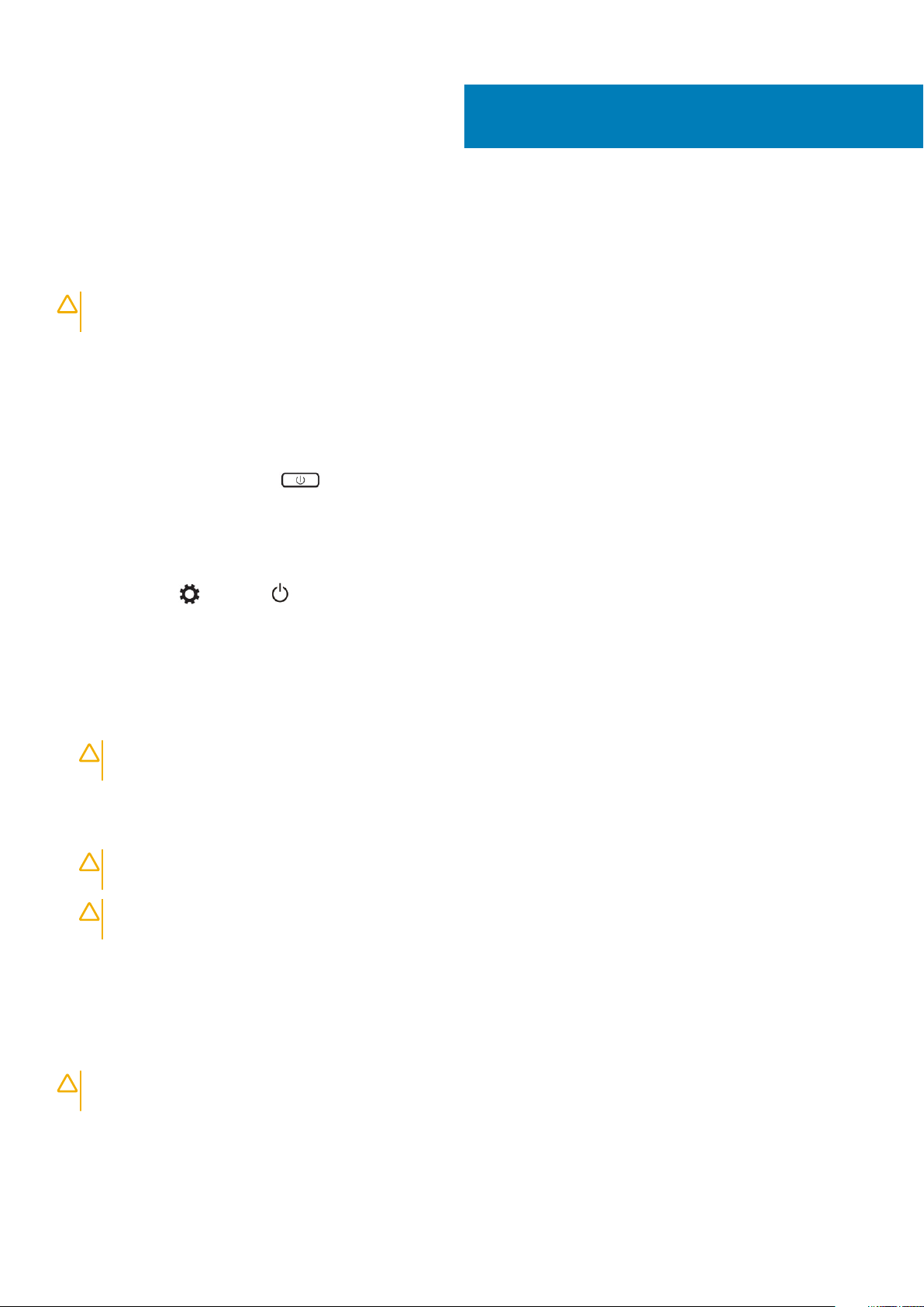
System Overview
2
Figure 1. Inside View — Back
power connector 2. system fan
1.
3. system board 4. hard drive
5. speakers 6. battery
7. I/O board cable 8. I/O board
9. WLAN card 10. video-card fan
11. memory modules 12. heatsink
Chassis 7
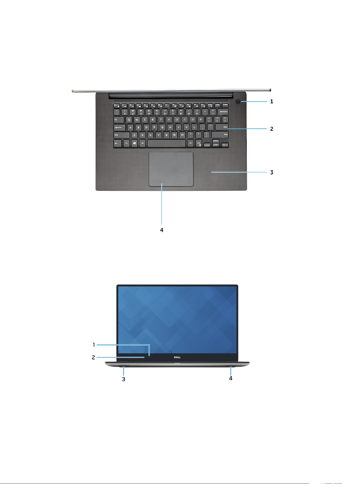
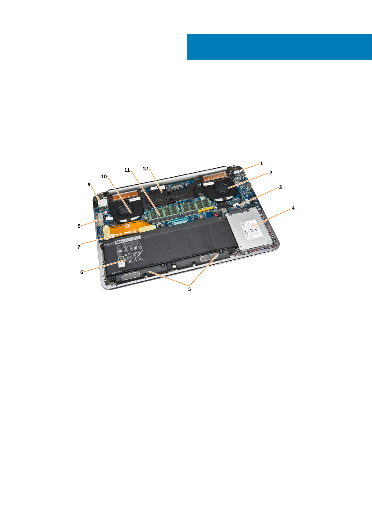
Figure 2. Front View
Power button 2. Keyboard
1.
3. Palmrest 4. Touchpad
Figure 3. Front Open View
1.
Camera 2. Camera-status light
3. Left speaker 4. Right speaker
8 Chassis
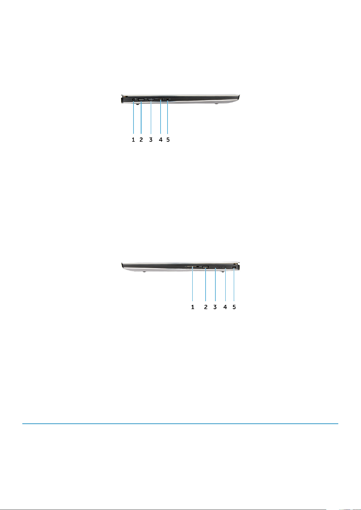
Figure 4. Left View
1. Power port 2. USB 3.0 port with PowerShare
3. HDMI port 4. Thunderbolt 3 port
5. Headset port
Figure 5. Right View
Memory card reader 2. USB 3.0 port with PowerShare
1.
3. Battery status lights 4. Battery status button
5. Kensington security slot
Hot key combinations
The table below details the hot key combinations.
Table 1. Hot key combination
Fn key combination Precision 5520
Fn+ESC Fn Toggle
Fn+ F1 Speaker Mute
Fn+ F2 Volume Down
Fn+ F3 Volume Up
Chassis 9

Fn key combination Precision 5520
Fn+ F4 Rewind
Fn+ F5 Play/Pause
Fn+ F6 Forward
Fn+ F8 Display Toggle (Win + P)
Fn+ F9 Search
Fn+ F10 Increase Keyboard Back light Brightness
Fn+ F11 Panel Brightness Down
Fn+ F12 Panel Brightness Up
Fn+ PrtScr Wireless
10 Chassis
Disassembly and reassembly
Recommended Tools
The procedures in this document may require the following tools:
• Small flat-blade screwdriver
• #0 Phillips screwdriver
• #1 Phillips screwdriver
• T5 Torx screwdriver
• Small plastic scribe
Base cover
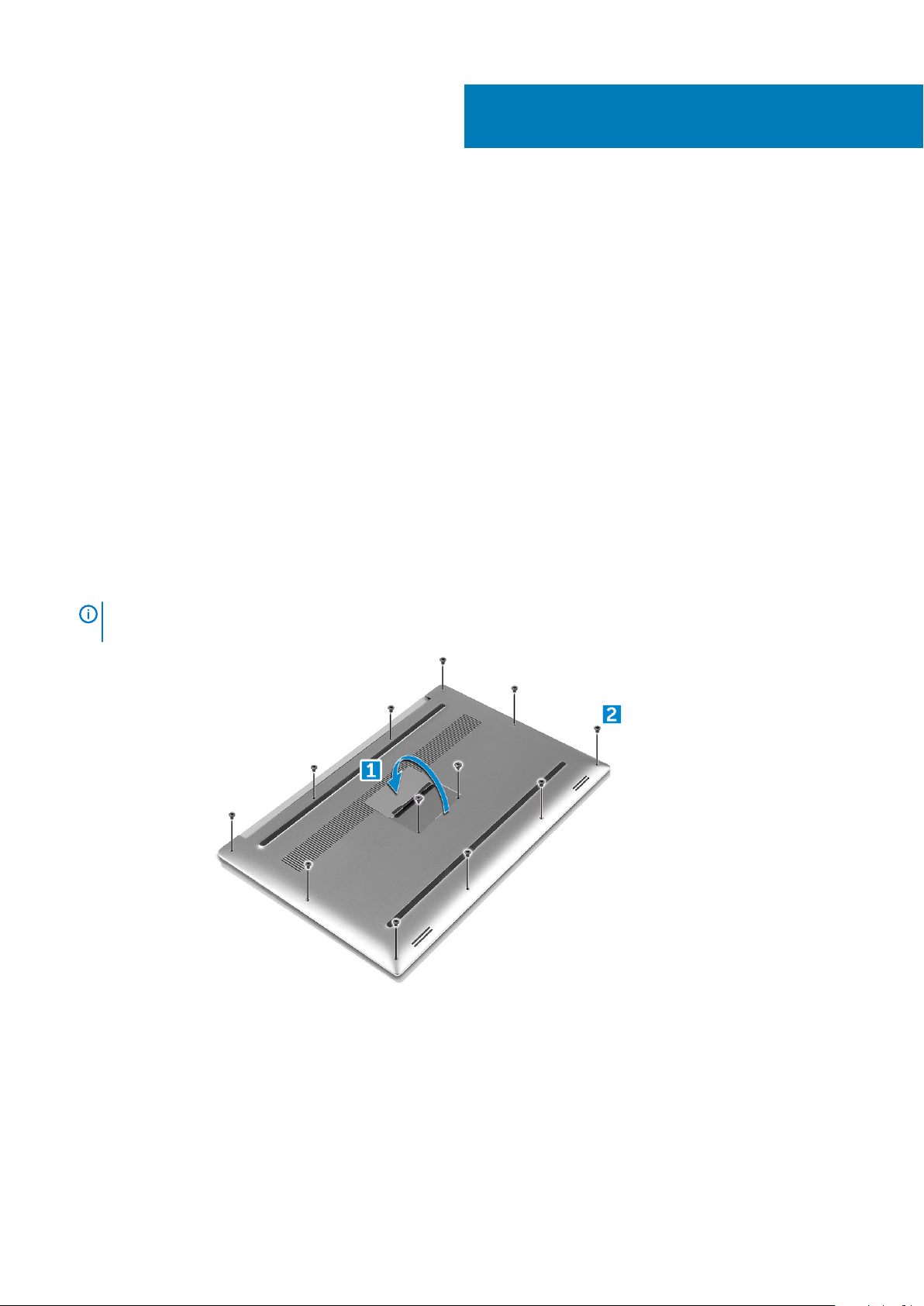
Removing the Base Cover
1. Follow the procedures in Before Working Inside Your Computer.
2. Close the display and turn the computer over.
3. Turn the system badge flap over (1) and then remove the ten M2x3 screws that secure the base cover to the computer (2).
NOTE:
badge flap.
Use a Torx #5 screwdriver for the base screws and a Philips screwdriver for the two M2x8 screws inside the
3
4. Pry the edges of the base cover and lift it to remove it from the computer.
Disassembly and reassembly 11
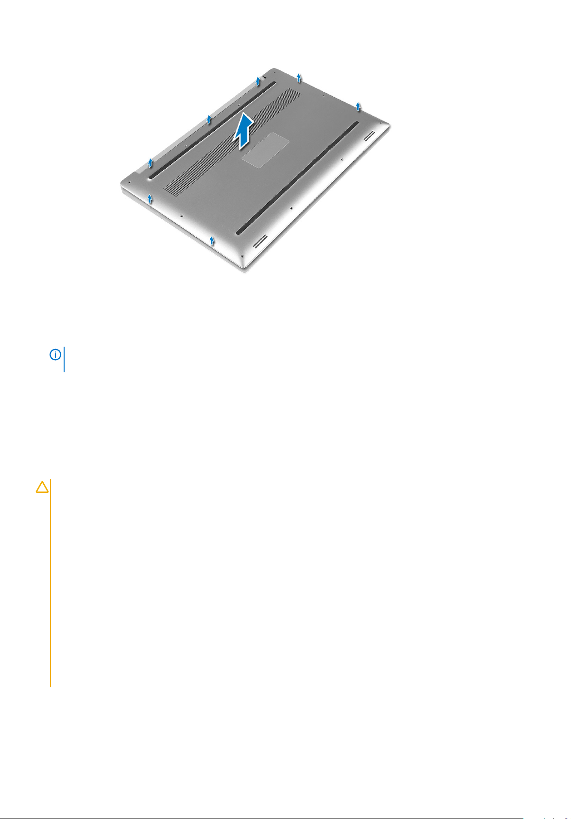
Installing the Base Cover
1. Place the base cover on the computer and snap it in place.
2. Tighten the ten M2x3 screws to secure the base cover to the computer.
NOTE:
badge screws.
3. Turn the system badge flap over and snap it in place.
4. Follow the procedures in After Working Inside Your Computer.
Ensure you use a Torx #5 screwdriver for the base screws and a Philips screwdriver for the two M2x8 system
Battery
Lithium-ion battery precautions
CAUTION:
• Exercise caution when handling Lithium-ion batteries.
• Discharge the battery as much as possible before removing it from the system. This can be done by disconnecting
the AC adapter from the system to allow the battery to drain.
• Do not crush, drop, mutilate, or penetrate the battery with foreign objects.
• Do not expose the battery to high temperatures, or disassemble battery packs and cells.
• Do not apply pressure to the surface of the battery.
• Do not bend the battery.
• Do not use tools of any kind to pry on or against the battery.
• Ensure any screws during the servicing of this product are not lost or misplaced, to prevent accidental puncture or
damage to the battery and other system components.
• If the battery gets stuck inside your computer as a result of swelling, do not try to release it as puncturing, bending,
or crushing a lithium-ion battery can be dangerous. In such an instance, contact Dell technical support for
assistance. See www.dell.com/contactdell.
• Always purchase genuine batteries from www.dell.com or authorized Dell partners and resellers.
12 Disassembly and reassembly
Removing the Battery
NOTE: Discharge the battery as much as possible before removing from the system. This can be done by disconnecting
the A/C adapter from the system (while the system is turned on) to allow the system to drain the battery.
1. Follow the procedures in Before Working Inside Your Computer.
2. Remove the Base cover
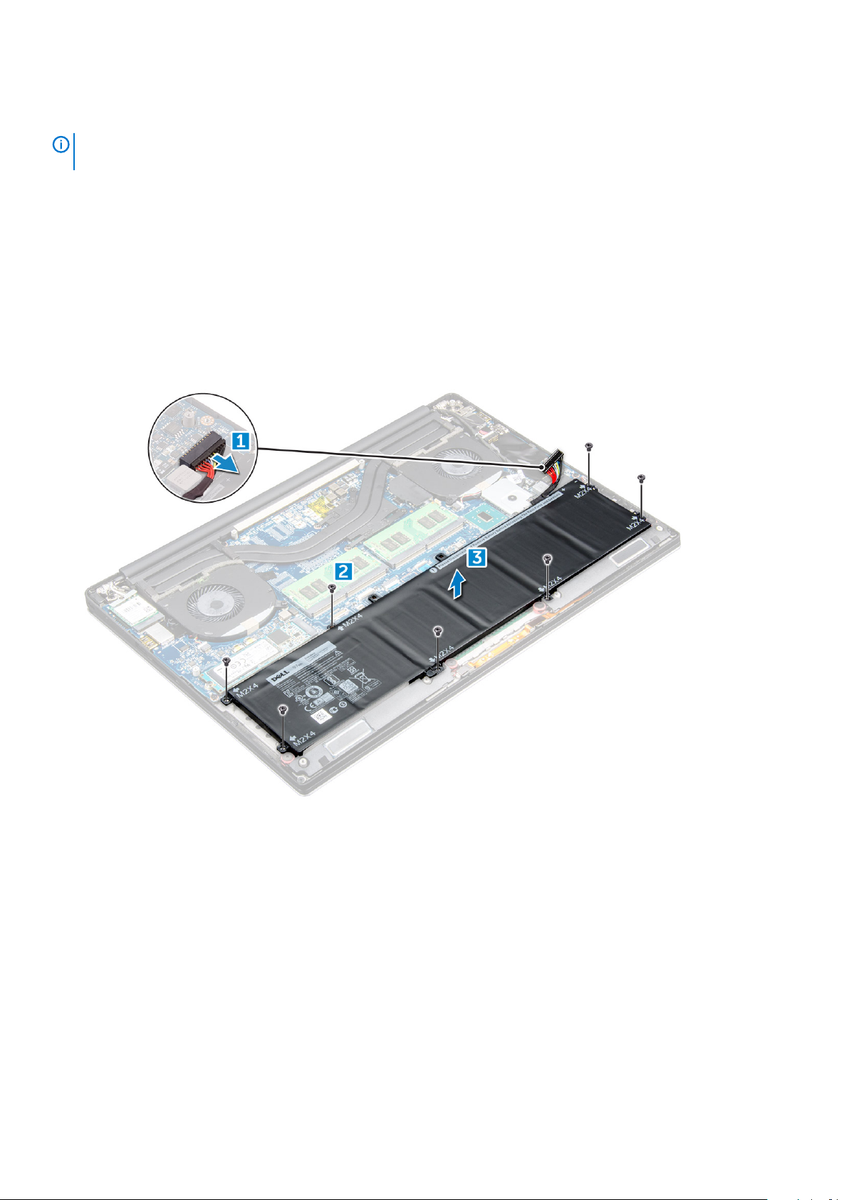
3. Perform the following steps to remove the battery:
a) Disconnect the battery cable from the system board [1].
b) Remove the seven M2x4 screws that secure the battery to the computer [2].
c) Lift the battery off the computer [3].
• Do not apply pressure to the surface of the battery
• Do not bend
• Do not use tools of any kind to pry on or against the battery
• If a battery cannot be removed within the constraints above, please contact Dell technical support
Installing the Battery
1. Place and align the battery in the battery bay.
2. Tighten the seven M2x4 screws that secure the battery to the computer.
3. Connect the battery cable to the system board.
4. Install the base cover.
5. Follow the procedures in After Working Inside Your Computer.
PCIe Solid State Drive (SSD)
Removing the Solid State Drive (SSD)
1. Follow the procedures in Before Working Inside Your Computer
Disassembly and reassembly
13
2. Remove the:
a) Base cover
b) battery
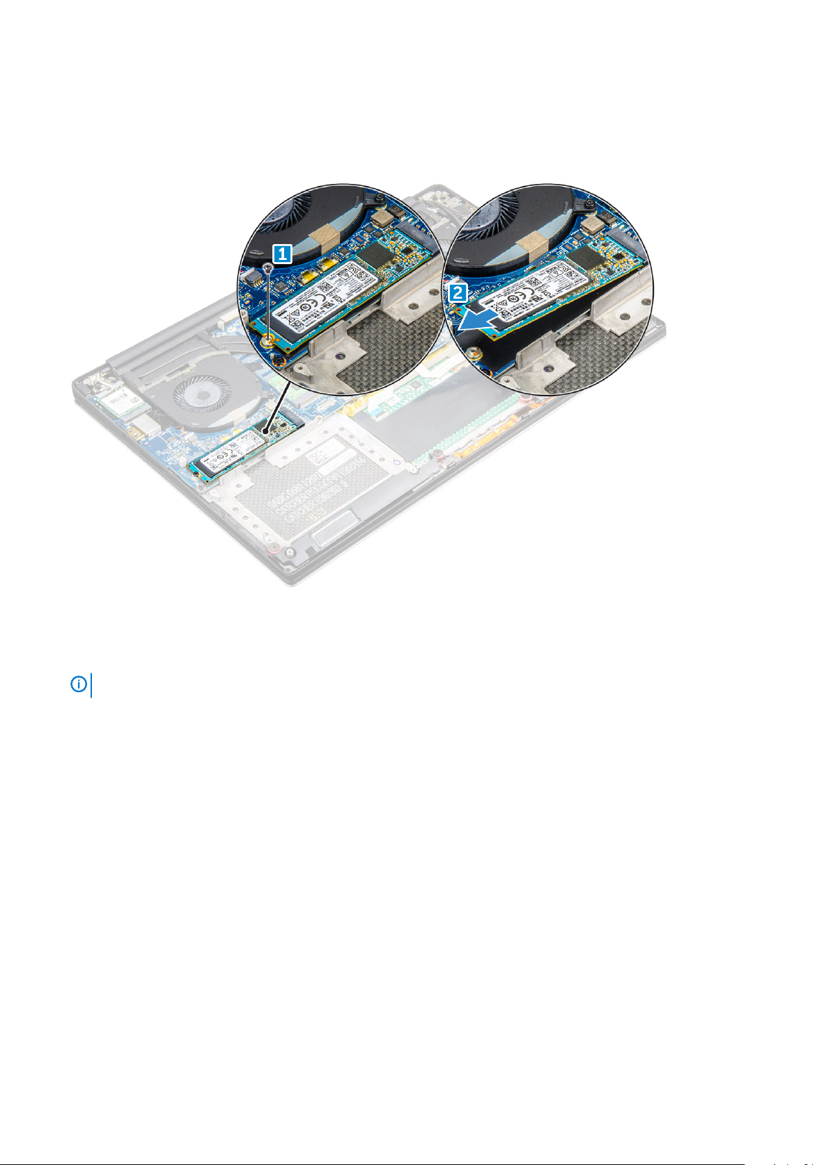
3. Remove the screw that secures the solid-state drive (SSD) to the system board [1]. Then, slide the SSD out from its connector on the
system board [2].
Installing the solid-state drive
1. Adhere the thermal pad to the solid-state drive.
NOTE:
2. Slide the solid-state drive at an angle into the solid-state drive slot.
3. Press the other end of the solid-state drive down and replace the M2 x 3 screw that secures the solid-state drive to the system board.
4. Install the:
a) battery
b) base cover
5. Follow the procedures in After Working Inside Your Computer.
The thermal pad is applicable only for a PCIe SSD card.
Hard drive
Removing the Hard Drive
1. Follow the procedures in Before Working Inside Your Computer.
2. Remove the:
a) Base cover
b) battery
3. Perform the following steps to remove the hard-drive bracket from the computer:
a) Remove the four M2x4 screws securing the hard-drive bracket to the computer [1].
b) Lift the hard-drive cage [2] off the hard drive assembly [3].
14
Disassembly and reassembly

4. Perform the following steps to remove the hard-drive:
a) Disconnect the hard-drive cable from the system board [1].
b) Lift the hard drive off the palm rest assembly [2].
5. Disconnect the hard drive interposer from the hard drive assembly and then remove the hard drive covers away from the hard drive.
Disassembly and reassembly
15

Installing the Hard Drive
1. Replace the hard-drive covers on the hard drive.
2. Connect the hard-drive interposer to the hard-drive assembly.
3. Place the hard-drive assembly on the palm-rest assembly.
4. Connect the hard-drive cable to the system board.
5. Align the screw holes on the hard-drive cage with the screw holes on the hard-drive assembly.
6. Replace the four M2x4 screws that secure the hard-drive cage to the palm-rest assembly.
7. Install the:
a) battery
b) base cover
8. Follow the procedures in After Working Inside Your Computer.
Speaker
Removing the Speakers
1. Follow the procedures in Before Working Inside Your Computer.
2. Remove the:
a) Base cover
b) battery
3. Perform the following steps to remove the speaker:
a) Disconnect the speaker cable from the audio board [1].
b) Remove the 4 M2x2 screws that secure the speakers to the computer [2].
c) Lift the speakers, along with the speaker cable, off the computer [3].
16
Disassembly and reassembly

Installing the Speakers
1. Using the alignment posts, place the speakers on the palm-rest assembly.
2. Replace the four M2x2 screws that secure the speakers to the palm-rest assembly.
3. Route the speaker cables through the routing guides on the palm-rest assembly.
4. Connect the speaker cable to the system board.
5. Install the:
a) battery
b) base cover
6. Follow the procedures in After Working Inside Your Computer.
Coin-cell battery
Removing the Coin-Cell Battery
1. Follow the procedures in Before Working Inside Your Computer.
CAUTION:
BIOS settings before removing the coin-cell battery.
2. Remove the:
a) base cover
b) battery
c) WLAN card
d) hard drive
e) fans
f) heatsink assembly
g) memory modules
h) system board
3. Perform the following steps to remove the coin-cell battery:
Removing the coin-cell battery re-sets the BIOS settings to default. It is recommended that you note the
Disassembly and reassembly
17

a) Turn the system board over.
b) Lift up the coin cell battery [1]
c) Disconnect the coin cell battery cable [2] from the system board [3].
Installing the Coin-Cell Battery
1. Replace the coin-cell battery in its slot in the computer.
2. Connect the coin-cell battery cable to the system board.
3. Turn the system board over.
4. Install the:
a) System Board
b) Memory
c) Heatsink assembly
d) Fans
e) Hard drive
f) WLAN card
g) Battery
h) Base cover
5. Follow the procedures in After Working Inside Your Computer.
Keyboard lattice and Keyboard
Removing the Keyboard
1. Follow the procedures in Before Working Inside Your Computer.
2. Remove the:
a) base cover
b) battery
c) fans
d) heatsink
e) SSD
f) memory module
g) system board
3. Perform the following steps to disconnect the keyboard and backlight connectors from the computer.
a) Lift up the connector lock [1] and the disconnect the cables from the connectors [2].
b) Peel back the screw shields [3].
18
Disassembly and reassembly

4. Un-route the LVDS cable [1] and then remove the 31 M1.6 x 1.5 screws that secure the keyboard to the computer [2].
5. Lift and remove the keyboard from the computer.
Disassembly and reassembly
19

Installing the Keyboard
1. Adhere the Mylar to the keyboard.
2. Align the screw holes on the keyboard with the screw holes on the palm-rest assembly.
3. Replace the 31 M1.6 x 1.5 screws that secure the keyboard to the palm-rest assembly.
4. Adhere the Mylar to the screws that secure the keyboard to the palm-rest assembly.
5. Connect the keyboard cable and keyboard-backlight cable to the keyboard-controls board.
6. Install the:
a) system board
b) hard drive
c) base cover
7. Follow the procedures in After Working Inside Your Computer.
WLAN card
Removing the WLAN Card
1. Follow the procedures in Before Working Inside Your Computer.
2. Remove the:
a) Base cover
b) battery
3. Perform the following steps to remove the WLAN card:
a) Remove the screw to release the bracket that secures the WLAN card to the computer [1] and lift the bracket away from the
computer [2].
b) Disconnect the antenna cables from the WLAN card [3].
c) Slide and remove the WLAN card from its connector on the board [4].
20
Disassembly and reassembly

Installing the WLAN Card
1. Align the notch on the WLAN card with the tab on the WLAN-card connector on the system board.
2. Align the bracket which secures the WLAN card to the palmrest assembly.
3. Connect the antenna cables to the WLAN card.
CAUTION:
NOTE: The color of the antenna cables is visible near the tip of the cables. The antenna-cable color scheme for the
WLAN card supported by your computer is as follows:
Table 2. Antenna-Cable Color Scheme for the WLAN Card
Connectors on the WLAN card Antenna-cable color
Main (white triangle) white
Auxiliary (black triangle) black
Multiple input, multiple output (grey triangle) Grey (optional)
4. Tighten the screw to secure the bracket and the WLAN card to the palmrest assembly.
5. Install the:
a) battery
b) base cover
6. Follow the procedures in After Working Inside Your Computer.
To avoid damage to the WLAN card, do not place any cables under it.
Memory modules
Removing the Memory Module(s)
1. Follow the procedures in Before Working Inside Your Computer.
2. Remove the:
Disassembly and reassembly
21

a) Base cover
b) battery
3. Pry the securing clips away from the memory module until it pops-up [1]. Then, remove the memory module from its connector on the
system board [2].
Installing the Memory Module(s)
1. Insert the memory module into the memory socket.
2. Press the memory module down until it clicks into place.
NOTE:
3. Install the:
a) battery
b) base cover
4. Follow the procedures in After Working Inside Your Computer.
If you do not hear the click, remove the memory module and re-install it.
System fan
Removing the Fans
1. Follow the procedures in Before Working Inside Your Computer.
2. Remove the:
a) Base cover
b) battery
3. Perform the following steps to remove the left video-card fan:
a) Disconnect the fan cable from the system board [1].
b) Remove the two M2x4 screws that secure the fan to the system board[2].
c) Lift the fan away from the computer [3]
22
Disassembly and reassembly

4. Perform the following steps to remove the right system fan:
a) Un-thread the LVDS cable from its restraints [1].
b) Disconnect the fan cable from the system board [2]
c) Remove the two M2x4 screws that secure the fan to the computer [3].
d) Lift the fan away from the computer [4].
Installing the Fans
1. Perform the following steps to install the system fan:
a) Align the screw holes on the left fan with the screw holes on the palm-rest assembly.
b) Connect the left fan cable to the system board.
c) Route the display cable through the routing guides on the left fan.
d) Replace the four M2x4 screws that secure the left fan to the system board.
e) Connect the right fan cable to the system board.
f) Route the touch-screen cable through the routing guides on the right fan.
g) Adhere the tape that secures the touch-screen cable to the right fan.
h) Connect the display cable to the system board.
i) Replace the four M2x4 screws that secure the right fan to the system board.
2. Follow the procedures in After Working Inside Your Computer.
Disassembly and reassembly
23

Heat sink
Removing the Heatsink
1. Follow the procedures in Before Working Inside Your Computer.
2. Remove the:
a) Base cover
b) battery
3. Remove the four M2x3 screws that secure the heatsink to the system board.
Lift the heatsink off the computer.
4.
24
Disassembly and reassembly

Installing the Heatsink
1. Align the screw holes on the heatsink with the screw holes on the system board.
2. Replace the screws to secure the heatsink to the system board.
3. Install the:
a) battery
b) base cover
4. Follow the procedures in After Working Inside Your Computer.
Power connector port
Removing the DC-in Connector
1. Follow the procedures in Before Working Inside Your Computer.
2. Remove the:
a) Base cover
b) battery
3. Perform the following steps to remove the I/O board:
a) Disconnect the DC-in cable from the system board [1].
b) Remove the M2x3 screw that secures the DC-in cable to the computer.
c) Remove the DC-in connector from the computer.
Disassembly and reassembly
25

Installing the DC-in Adapter Port
1. Place the DC-in adapter port into the slot on the palm-rest assembly.
2. Route the power-adapter port cable through its routing guides on the palm-rest assembly.
3. Replace the M2x3 screw that secures the power-adapter port to the palm-rest assembly.
4. Connect the power-adapter port cable to the system board.
5. Install the:
a) battery
b) base cover
6. Follow the procedures in After Working Inside Your Computer.
Antenna cover
Removing the antenna cover
1. Follow the procedures in Before Working Inside Your Computer.
2. Remove the:
a) base cover
b) battery
c) WLAN Card
d) display assembly
3. Carefully turn the display hinges at an angle.
26
Disassembly and reassembly

Figure 6. Turning the display hinge
a. display assembly
b. display hinges (2)
4. Slide and lift the antenna cover away from the display assembly.
Figure 7. Removing the antenna cover
a. display assembly
b. antenna cover
Installing the antenna cover
1. Replace the antenna cover on the display assembly.
2. Turn the display hinges to the normal position.
3. Install the:
a) display assembly
b) wireless card
c) battery
d) base cover
4. Follow the procedures in After Working Inside Your Computer.
Disassembly and reassembly
27

Display Assembly
Removing the Display Assembly
1. Follow the procedures in Before Working Inside Your Computer.
2. Remove the:
a) Base cover
b) battery
3. Perform the following steps:
a) Remove the screw securing the metal bracket [1].
b) Lift the metal bracket off the computer [2].
c) Disconnect the LVDS cable from the system board [3].
4. Place the computer at the edge of a table as shown and remove the six M2.5x5 screws [1] securing the display assembly to the
computer. Then, lift the display assembly off the computer [2].
28
Disassembly and reassembly

Installing the Display Assembly
1. Place the palm-rest assembly at the edge of the table with the speakers facing away from the edge.
2. Align the screw holes on the palm-rest assembly with the screw holes on the display hinges.
3. Replace the six M2.5 x 5 screws that secure the display hinges to the palm-rest assembly.
4. Adhere the tape and route the touch-screen cable through the routing guides on the fan.
5. Connect the touch-screen cable and display cable to the system board.
6. Replace the screw that secures the display-cable bracket to the system board.
7. Follow the procedures in After Working Inside Your Computer.
System board
Removing the System Board
1. Follow the procedures in Before Working Inside Your Computer.
2. Remove the:
a) base cover
b) battery
c) fans
d) heatsink
e) SSD
f) memory module
Disassembly and reassembly
29

NOTE: Your computer’s Service Tag is located under the system badge flap. You must enter the Service Tag in the
BIOS after you replace the system board.
NOTE: Before disconnecting the cables from the system board, note the location of the connectors so that you can
re-connect them correctly after you replace the system board.
3. Remove the M2x2 screw securing the metal bracket for the LVDS to the system board [1] and remove the bracket off the computer
[2]. Then, disconnect the LVDS cable from the system board [3].
4. Slide out the connector latches to disconnect all the cables from the system board.
5. Perform the following steps to remove the system board from the computer:
a) Remove the five M2x4 screws that secure the system board to the computer [1].
b) Lift the system board off the computer [2].
30
Disassembly and reassembly

Installing the System Board
1. Align the system board on the computer.
2. Replace the five M2x4 screws that secure the system board to the palm-rest assembly.
3. Connect the power-adapter port cable, speaker cable, keyboard-control board cable, touch-pad cable, and touch-screen cable to the
system board.
4. Connect the display cable to the system board.
5. Align the screw hole on the display-cable bracket with the screw hole on the system board.
6. Follow the procedures in After Working Inside Your Computer.
Palm rest
Removing the Palmrest Assembly
1. Follow the procedures in Before Working Inside Your Computer.
2. Remove the:
a) base cover
b) battery
c) memory modules
d) hard drive
e) WLAN card
f) speakers
g) heatsink assembly
h) fans
i) display assembly
j) power adapter port
k) system board
l) keyboard
Disassembly and reassembly
31

3. After performing the above steps, we are left with the palmrest assembly [1].
Installing the Palm rest Assembly
1. Align the palm rest assembly on the display assembly.
2. Tighten the screws to secure the display hinges to the palm rest assembly.
3. Press down on the palm rest assembly to close the display.
4. Install the:
a) keyboard
b) system board
c) power connector port
d) display assembly
e) fans
f) heatsink assembly
g) speakers
h) WLAN card
i) hard drive(optional)
j) memory modules
k) battery
l) base cover
5. Follow the procedures in After Working Inside Your Computer
32
Disassembly and reassembly

4
Diagnostics
If you experience a problem with your computer, run the ePSA diagnostics before contacting Dell for technical assistance. The purpose of
running diagnostics is to test your computer's hardware without requiring additional equipment or risking data loss. If you are unable to fix
the problem yourself, service and support personnel can use the diagnostics results to help you solve the problem.
Topics:
• Enhanced Pre-Boot System Assessment — ePSA diagnostics
• Device Status Lights
Enhanced Pre-Boot System Assessment — ePSA diagnostics
The ePSA diagnostics (also known as system diagnostics) performs a complete check of your hardware. The ePSA is embedded with the
BIOS and is launched by the BIOS internally. The embedded system diagnostics provides a set of options for particular devices or device
groups allowing you to:
The ePSA diagnostics can be initiated by the FN+PWR buttons while powering on the computer.
• Run tests automatically or in an interactive mode
• Repeat tests
• Display or save test results
• Run thorough tests to introduce additional test options to provide extra information about the failed device(s)
• View status messages that inform you if tests are completed successfully
• View error messages that inform you of problems encountered during testing
NOTE:
terminal when the diagnostic tests are performed.
Some tests for specific devices require user interaction. Always ensure that you are present at the computer
Device Status Lights
Table 3.
Icon Description
Turns on when you turn on the computer.
Battery status lights
If the computer is connected to an electrical outlet, the battery light operates as follows:
Alternately
blinking amber
light and white
light
Alternately
blinking amber
light with steady
white light
Constantly
blinking amber
light
An unauthenticated or unsupported non-Dell AC adapter is attached to your laptop. Replug battery connector,
replace battery if the issue recurs.
Temporary battery failure with AC adapter present. Replug battery connector, replace battery if the issue recurs.
Fatal battery failure with AC adapter present. Fatal battery, replace the battery.
Diagnostics 33

Light off Battery in full charge mode with AC adapter present.
White light on Battery in charge mode with AC adapter present.
Diagnostic LED
Occasionally the computer may indicate bicolor flashes on Battery Charge LED. A specific blink pattern, flashing a pattern of amber,
followed by white, and then the same pattern repeats.
NOTE: The diagnostic pattern consists of a two-digit number that is represented by a first group of amber LED blinks (1
through 9), followed by a 1.5-second pause with the LED off, and then a second group of LED blinks (1 through 9) in
white. Followed by a three-second pause, with the LED off, before repeating over again. Each LED blink takes 0.5 s.
The system does not shut down when displaying the Diagnostic Error Codes. Diagnostic Error Codes supersedes any other use of the
LED. For instance, on laptops, battery codes for Low Battery or Battery Failure situations are not displayed when the Diagnostic Error
Codes are being displayed:
Table 4. LED pattern
Blinking pattern Problem Description Suggested Resolution
AmberWhite
2 1 processor processor failure
2 2 system board, BIOS ROM system board, covers BIOS corruption or ROM error
2 3 memory no memory/no RAM detected
2 4 memory memory failure/RAM failure
2 5 memory invalid memory installed
2 6 system board; chipset system board/ chipset error
2 7 display display failure
3 1 RTC power failure coin-cell battery failure
3 2 PCI/Video PCI/Video card/chip failure
3 3 BIOS recovery 1 recovery image nor found
3 4 BIOS recovery 2 recovery image found but invalid
34 Diagnostics

System Setup Options
NOTE: Depending on your computer and its installed devices, the items listed in this section may or may not appear.
Table 5. Main
Option Description
System Time/Date Allows you to set the date and time.
BIOS Version Displays the BIOS version.
Product Name Displays the product name.
Dell Precision 5520 (Default Setting)
Service Tag Displays the service tag.
Asset Tag Displays the asset tag.
None (Default Setting)
CPU Type Displays the CPU type.
CPU Speed Displays the CPU speed.
CPU ID Displays the CPU ID.
CPU Cache Displays the sizes of the CPU caches.
Fixed HDD Displays the type and size of the HDD.
mSATA Device Displays the type and size of the mSATA device.
AC Adapter Type Displays the type of the AC adapter.
None (Default Setting)
5
System Memory Displays the size of the system memory.
Extended Memory Displays the size of the extended memory.
Memory Speed Displays the speed of the memory.
Keyboard Type Displays the type of keyboard.
Backlite (Default Setting)
Table 6. Advanced
Option Description
Intel (R) SpeedStep (TM) Allows you to enable or disable the Intel (R) SpeedStep (TM) feature.
Enabled (Default Setting)
Virtualization This option specifies whether a Virtual Machine Monitor (VMM) can utilize the additional hardware
capabilities provided by Intel Virtualization technology. Allows you to enable or disable the
Virtualization feature.
Enabled (Default Setting)
Multi Core Support Specifies whether the processor will have one or more cores enabled. All (Default Setting)
Intel TurboBoost Enables or disables the Intel TurboBoost mode of the processor. Enabled (Default Setting)
C-States Control This option enables or disables additional processor sleep states. Enabled (Default Setting)
Audio Enables or disables the integrated audio controller. Enabled (Default Setting)
System Setup Options 35

Option Description
Keyboard Illumination This field lets you choose the operating mode of the keyboard illumination feature. Disabled
(Default Setting)
USB Configuration
Touchscreen This field controls whether the touchscreen is enabled or disabled. Enabled (Default Setting)
AC Behavior Allows the system (if OFF or in Hibernate) to power-on automatically when AC is inserted.
Wake On LAN Allows the computer to power up from the off state when triggered by special LAN. Disabled
Advanced Battery Charge
Configuration
Block Sleep Lets you to block entering to sleep (S3 state) in OS environment. Disabled (Default Setting)
Auto On Time Sets the time of day when you would like the system to turn on automatically. Disabled (Default
Peak Shift Minimizes AC power usage at times of peak demand. Disabled (Default Setting)
USB Wake Support Allows you to enable USB devices to wake the system from Standby. Enabled (Default Setting)
LCD Brightness This options sets the panel brightness independently for Battery and AC power.
USB Emulation Allows you to enable or disable the USB Emulation feature.
Allows you to configure the integrated USB controller.
Default Enabled: Enable Boot Support, Enable Thunderbolt Ports; Always Allow Dell Docks; Enable
External USB Port
(Default Setting)
Maximizes battery health while still supporting heavy use during the work day. Disabled (Default
Setting)
Setting)
Enabled (Default Setting)
USB PowerShare Allows you to enable or disable the USB PowerShare feature.
Enabled (Default Setting)
USB Wake Support This option allows you to enable USB devices to wake the system from Standby.
Disable(Default Setting)
SATA Operation Displays the SATA Operation information.
Adapter Warnings Allows you to enable or disable the adapter warnings feature.
Multimedia Key Behaviour
Battery Health Displays the battery health information.
Battery Charge Configuration
Miscellaneous Devices Allows you enable or disable the various on board devices. The options are:
Table 7. Security
Option Description
Unlock Setup Status
Admin Password Status Displays the status of the admin password.
Function Key (Default Setting)
Adaptive (Default Setting)
• External USB Ports - Enabled (Default Setting)
• USB Debug - Disabled (Default Setting)
Unlocked (Default Setting)
Default Setting: Not set
System Password Status Displays the status of the system password.
Default Setting: Not set
HDD Password Status Displays the status of the system password.
Default Setting: Not set
36 System Setup Options

Option Description
Asset Tag Allows you to set the asset tag.
Admin Password Allows you to set, change, or delete the administrator (admin) password.
NOTE: You must set the admin password before you set the system or hard drive
password.
NOTE: Successful password changes take effect immediately.
NOTE: Deleting the admin password automatically deletes the system password
and the hard drive password.
NOTE: Successful password changes take effect immediately.
System Password Allows you to set, change or delete the system password.
NOTE: Successful password changes take effect immediately.
HDD Password Allows you to set, change or delete the administrator password.
Strong Password This field enforces strong passwords that contain at least one uppercase character, one
lowercase character, and be at least 8 characters long.
Password Change Allows you to enable or disable permissions to set a System password and a Hard Drive
password when the admin password is set.
Default Setting: Permitted
Password Bypass This option lets you bypass the System (Boot) password and the internal HDD password
prompts during system re-start. Disabled (Default Setting)
Password configuration These fields control the minimum and maximum number of characters allowed for Admin and
System passwords.
Computrace Allows you to activate or disable the optional Computrace software The options are:
• Deactivate (Default Setting)
• Activate
NOTE: The Activate and Disable options will permanently activate or disable the
feature and no further changes will be allowed.
TPM Security This option lets you control whether the Trusted Platform Module (TPM) in the system is
enabled and visible to the operating system. When disabled the BIOS will not turn On the TPM
During POST. The TPM will be non-functional and invisible to the operating system. When
enabled, the BIOS will turn On the TPM during POST so that it can be used by the operating
system. This option is
NOTE: Disabling this option does not change any settings you may have made to
the TPM, nor does it delete or change any information or keys you may have
stored there. It simply turns Off the TPM so that it cannot be used. When you reenable this option, the TPM will function exactly as it did before it was disabled.
NOTE: Changes to this option take effect immediately.
UEFI Capsule Firmware Updates This option controls whether this system allows BIOS updates via UEFI capsule update
packages. Enabled (Default Setting)
CPU XD Support This option enables or disables the Execute Disable mode for the processor. Enabled (Default
Setting)
OROM Keyboard Access This option determines whether users are able to enter Option ROM configuration screens via
hotkeys during boot.
Table 8. Boot
Option Description
Boot List Option
Secure Boot This option enables or disables the Secure Boot feature.
Default Setting: Legacy
Enable by default.
System Setup Options 37

Option Description
• Disabled (Default Setting) - Windows 7 (Intel Core Xeon E3–1505M v5 and Intel Core i7–
6820HQ processors)
• Enabled - Windows 8.1 and Windows 10 (Intel Core Xeon E3–1505M; Intel Core i7–7820HQ;
Intel Core i7–7700HQ; Intel Core i5–7440HQ; and Intel Core i5–7300HQ processors)
Load Legacy Option ROM This option enables or disables the Load Legacy Option ROM feature.
• Enabled (Default Setting) - Windows 7
• Disabled - Windows 8.1 and Windows 10
Expert Key Management Expert Key Management allows the PK, KEK, db, and dbx security key databases to be
manipulated. Disabled (Default Setting)
Intel Software Guard Extensions Intel SGX Enabled: Enables Intel Software Guard Extensions (SGX) to provide a secured
environment for running code/storing sensitive information in the context of the main OS.
Software Controlled (Default Setting)
Set Boot Priority Allows you to change the order in which the computer attempts to find an operating system:
• 1 st Boot Priority [ CD/DVD/CD-RW Drive]
• 2nd Boot Priority [Network]
• 3rd Boot Priority [mini SSD]
• 4th Boot Priority [USB Storage Device
• 5th Boot Priority [Hard Drive]
• 6th Boot Priority [Diskette Drive]
Adapter Warnings Lets you choose whether the system displays warning messages when you use certain power
adapters. Enabled (Default Setting)
SupportAssist OS Recovery Enables for disables the boot flow for SupportAssist OS Recovery tool in the event of certain
errors. Enabled (Default Setting)
Keypad (embedded) Lets you choose one of two methods to enable the keypad that is embedded in the internal
keyboard. Fn Key Only Enabled by default.
Fastboot This option can speed up the boot process by bypassing some compatibility steps. Minimal
(Default Setting)
Extend BIOS POST Time Creates an additional pre-boot delay to see POST messages.
Warnings and Errors This option cause the boot process to only pause when warnings or errors are detected.
Enabled (Default Setting)
Wireless Switch Determines which wireless devices can be controlled by the Wireless Switch. WLAN and
Bluetooth Enabled (Default Setting)
SupportAssist System Resolution Auto OS Recovery Threshold: Controls the automatic boot flow for SupportAssist System
Resolution Console and for Dell OS Recovery Tool. Setting 2 default
Table 9. Exit
Option Description
Save Changes and Reset Allows you to save the changes you made.
Discard Changes and Reset Allows you to discard the changes you made.
Restore Defaults Allows you to restore the default options.
Discard Changes Allows you to discard the changes you made.
Save Changes Allows you to save the changes you made.
38 System Setup Options

Technical Specifications
NOTE: Offerings may vary by region. For more information regarding the configuration of your computer, click Start
(Start icon) > Help and Support, and then select the option to view information about your computer.
Table 10. System Information
Feature Specification
System Chipset Mobile Intel HM175 Express Chipset / Intel CM238
DMA Channels two VT-d DMA remap engines
Interrupt Levels Intel 64 and IA-32 Architecture
BIOS Chip (NVRAM) 32 MB SPI ROM
Table 11. Processor
Feature Specification
Processor type 6th Generation:
• Intel Core Xeon E3–1505M v5
• Intel Core i7–6820HQ
7th Generation
• Intel Core Xeon E3–1505M v6
• Intel Core i7–7820HQ
• Intel Core i7–7700HQ
• Intel Core i5–7440HQ
• Intel Core i5–7300HQ
6
L1 cache up to 256 KB cache depending on processor type
L2 cache up to 1024 KB cache depending on processor type
L3 cache up to 6144 KB cache depending on processor type
Table 12. Memory
Feature Specification
Type DDR4
Speed 2400 MHz
NOTE: 2133 MHz with 6th Generation processors
Connectors 2 SoDIMM Sockets
Capacity 8 GB, 16 GB, and 32 GB
Minimum Memory 8 GB (2 x 4 GB)
Maximum memory 32 GB
Table 13. Video
Feature Specification
Type
Discrete NVIDIA Quadro M1200 / 4 GB GDDR5
Technical Specifications 39

Feature Specification
Integrated
Data bus PCIE x16, Gen3
Memory
Discrete Up to 4 GB GDDR5
Integrated Shared system memory
Table 14. Audio
Feature Specification
Integrated dual-channel High-Definition audio
Table 15. Communication
Feature Specification
Network adapter Ethernet via USB-to-Ethernet Dongle (Optional).
• Intel HD Graphics 630/P630 with 7th Generation processors
• Intel HD Graphics 530 with 6th Generation processors
NOTE: No RJ45 (10/100/1000Base-T, IPv6) provided.
Wireless
Table 16. Ports and Connectors
Feature Specification
Audio
USB 3.0
Video
Memory card reader SD 4.0
Table 17. Display
Feature Specification
Type 1920 x 1080 FHD
• Wi-Fi 802.11ac
• Wi-Fi 802.11a/g/n
• Bluetooth 4.2
• Miracast
• One headset port (headphone and microphone combo)
• two USB 3.0 ports with PowerShare
• One Thunderbolt 3 port (USB-C)
• one HDMI 1.4
3840 x 2160 UltraHD Touch
100% Adobe Color gamut minimum
Size 15.6 inches FHD
15.6 inches UltraHD
Dimensions:
Height 194.50 mm (7.66 in)
Width 345.60 mm (13.61 in)
Diagonal 396.52 mm (15.61 in)
Active area (X/Y) 194.50 mm (7.66 in) x 345.60 mm (13.61 in) x 396.52 mm (15.61 in)
Maximum resolution 1920 X 1080 pixels / 3840 X 2160 pixels
Maximum Brightness 400 nits
40 Technical Specifications

Feature Specification
Operating angle 0° (closed) to 135°
Refresh rate 60 Hz
Minimum viewing angles:
Horizontal 80/80
Vertical 80/80
Table 18. Keyboard
Feature Specification
Number of keys
Layout QWERTY/AZERTY/Kanji
Table 19. Touchpad
Feature Specification
Active Area:
X-axis 105 mm
Y-axis 80 mm
• United States: 80 keys
• United Kingdom: 81 keys
• Brazil: 80 keys
• Japan: 84 keys
Table 20. Camera
Feature Specification
Type HD Camera / Digital Array Microphone
Still Resolution 0.92 megapixels (Maximum)
Video Resolution 1280 x 720 pixels (HD) at 30 frames per second (Maximum)
Diagonal 74 degrees
Table 21. Storage
Feature Specification
Storage:
Storage Interface SATA 3 Gbps
SATA 6 Gbps
PCIe 8 Gbps
Drives configurations:
Hard Drives (optional) one internal 2.5 inch SATA HDD (supports Intel Smart Response Technology)
Solid State Drives (optional) one Solid State Drive (SSD), with Intel Cache support
Size: 512 GB / 1 TB/ 2 TB HDD
256 GB / 360 GB / 512 GB / 1 TB SSD
Table 22. Battery
Feature Specification
Type Li-polymer 3-cell (56 Whr) / 6-cell (97 Whr)
Dimensions :
56 Whr :
Technical Specifications 41

Feature Specification
Depth 223.20 mm (8.79 in)
Height 7.20 mm (0.28 in)
Width 71.80 mm (2.83 in)
Weight 0.54 lb (0.24 kg)
84 Whr :
Depth 330.50 mm (13.01 in)
Height 7.20 mm (0.28 in)
Width 71.80 mm (2.83 in)
Weight 0.76 lb (0.34 kg)
Voltage 11.4 V
Life span 300 discharge/charge cycles
Temperature range:
Operating (approximate)
Non-operating –40 °C to 65 °C (–40 °F to 149 °F)
Coin-cell battery ML1220
• Operating: 0 °C to 35 °C (32 °F to 95 °F)
• Charge : 0 °C to 50 °C (32 °F to 122 °F)
• Discharge: 0 °C to 70 °C (32 °F to 158 °F)
Table 23. AC Adapter
Feature Specification
Input voltage 100 VAC to 240 VAC
Input current (maximum) 1.80 A
Input frequency 50 Hz to 60 Hz
Output power 130 W
Output current 6.67 A
Rated output voltage 19.50 VDC
Dimensions:
Height 22 mm (0.86 inches)
Width 66 mm (2.59 inches)
Depth 143 mm (5.62 inches)
Temperature range:
Operating 0 °C to 40 °C (32 °F to 104 °F)
Non Operating –40 °C to 70 °C (–40 °F to 158 °F)
Table 24. Physical Dimensions
Physical Specification
Height: 17 mm (0.66 in)
Width 357 mm (14.06 in)
Depth 235 mm (9.27 in)
Weight (Minimum) 2 kg (4.41 lb)
42 Technical Specifications

Table 25. Environmental
Feature Specification
Temperature range:
Operating 0 °C to 40 °C (32 °F to 104°F)
Storage –40 °C to 70 °C (–40 °F to 158 °F)
Relative humidity (maximum):
Operating 10 % to 90 % (non-condensing)
Storage 10 % to 95 % (non-condensing)
Maximum vibration:
Operating 0.66 GRMS, 2 Hz - 600 Hz
Storage 1.3 GRMS, 2 Hz - 600 Hz
Maximum shock:
Operating 110 G, 2 ms
Non-operating 160 G, 2 ms
Altitude:
Operating
Storage 15.2 m to 10,668 m (–50 ft to 35,000 ft)
Airborne contaminant level G1 as defined by ISA-S71.04-1985
–15.2 m to 30482000 m (–50 to 10,0006560 ft)
Technical Specifications 43

7
Contacting Dell
NOTE: If you do not have an active Internet connection, you can find contact information on your purchase invoice,
packing slip, bill, or Dell product catalog.
Dell provides several online and telephone-based support and service options. Availability varies by country and product, and some services
may not be available in your area. To contact Dell for sales, technical support, or customer service issues:
1. Go to Dell.com/support.
2. Select your support category.
3. Verify your country or region in the Choose a Country/Region drop-down list at the bottom of the page.
4. Select the appropriate service or support link based on your need.
44 Contacting Dell
 Loading...