


Dell Precision 5510
Owner's Manual
Regulatory Model: P56F
Regulatory Type: P56F001

Notas, precauciones y advertencias
NOTA: Una NOTA indica información importante que le ayuda a hacer un mejor uso de su producto.
PRECAUCIÓN: Una ADVERTENCIA indica un potencial daño al hardware o pérdida de datos y le informa cómo evitar el
problema.
AVISO: Una señal de PRECAUCIÓN indica la posibilidad de sufrir daño a la propiedad, heridas personales o la muerte.
Copyright © 2017 Dell Inc. o sus subsidiarias. Todos los derechos reservados. Dell, EMC y otras marcas comerciales son marcas
comerciales de Dell Inc. o sus subsidiarias. Puede que otras marcas comerciales sean marcas comerciales de sus respectivos propietarios.
2015 - 10
Rev. A00

Contents
1 Manipulación del equipo................................................................................................................ 5
Apagado del equipo............................................................................................................................................................... 5
Antes de manipular el interior del equipo............................................................................................................................ 5
Después de manipular el interior del equipo....................................................................................................................... 5
2 Extracción e instalación de componentes....................................................................................... 7
Herramientas recomendadas................................................................................................................................................7
Removing the Base Cover.................................................................................................................................................... 7
Installing the Base Cover...................................................................................................................................................... 8
Removing the Battery...........................................................................................................................................................8
Installing the Battery............................................................................................................................................................. 9
Removing the Hard Drive..................................................................................................................................................... 9
Installing the Hard Drive...................................................................................................................................................... 10
Removing the Solid-State Drive (half-length)................................................................................................................. 10
Installing the Solid-State Drive (half-length).....................................................................................................................11
Removing the Solid-State Drive (full-length)....................................................................................................................11
Installing the Solid-State Drive (full-length)..................................................................................................................... 12
Removing the Speakers ................................................................................................................................................. 13
Installing the Speakers.........................................................................................................................................................13
Removing the WLAN Card..................................................................................................................................................13
Installing the WLAN Card.................................................................................................................................................... 14
Removing the Fans ............................................................................................................................................................. 14
Installing the Fans.................................................................................................................................................................15
Removing the Heatsink....................................................................................................................................................... 16
Installing the Heatsink..........................................................................................................................................................16
Removing the Memory Module(s)..................................................................................................................................... 17
Installing the Memory Module(s)....................................................................................................................................... 17
Removing the System Board.............................................................................................................................................. 17
Installing the System Board................................................................................................................................................ 19
Removing the Audio Daughter Board................................................................................................................................19
Installing the audio daughter board...................................................................................................................................20
Removing the Keyboard......................................................................................................................................................21
Installing the Keyboard........................................................................................................................................................22
Removing the Display Assembly........................................................................................................................................ 22
Installing the Display Assembly.......................................................................................................................................... 23
Removing the DC-in Connector........................................................................................................................................ 24
Installing the DC-in Adapter Port...................................................................................................................................... 24
Removing the antenna cover.............................................................................................................................................24
Installing the antenna cover............................................................................................................................................... 25
Removing the display hinges..............................................................................................................................................26
Installing the display hinges................................................................................................................................................ 26
Removing the antenna module.......................................................................................................................................... 27
Installing the antenna module.............................................................................................................................................27
Removing the palm-rest assembly.................................................................................................................................... 28
Contents 3

Installing the palm-rest assembly...................................................................................................................................... 28
3 System Setup (Configuración del sistema)...................................................................................30
Secuencia de arranque....................................................................................................................................................... 30
Teclas de navegación..........................................................................................................................................................30
System Setup Options.........................................................................................................................................................31
Actualización de BIOS en Windows.................................................................................................................................. 33
Contraseña del sistema y de configuración......................................................................................................................34
Asignación de contraseña del sistema y de configuración....................................................................................... 34
Eliminación o modificación de una contraseña del sistema y de configuración existente....................................35
4 Diagnóstico................................................................................................................................36
Diagnósticos Enhanced Pre-boot System Assessment (Evaluación del sistema de preinicio ePSA)...................... 36
Device Status Light.............................................................................................................................................................36
5 Technical Specifications............................................................................................................. 37
6 Cómo ponerse en contacto con Dell............................................................................................. 42
4 Contents
Manipulación del equipo
Apagado del equipo
PRECAUCIÓN: Para evitar la pérdida de datos, guarde todos los archivos que tenga abiertos y ciérrelos, y salga de todos
los programas antes de apagar el equipo.
Puede apagar el equipo de dos maneras:
1. Uso del botón de encendido
2. Uso del menú de accesos
Uso del botón de encendido
1. Presione y mantenga presionado el del botón Alimentación para apagar la pantalla.
Uso de accesos
1. Deslice el dedo desde el borde derecho de la pantalla para acceder al menú Charms (accesos).
1
2. Toque Configuración —> Alimentación —> Apagar para apagar el equipo.
Antes de manipular el interior del equipo
1. Asegúrese de que la superficie de trabajo sea plana y esté limpia para evitar que se raye la cubierta del equipo.
2. Apague el equipo.
3. Si el equipo está conectado a un dispositivo de acoplamiento (acoplado), desacóplelo.
4. Desconecte todos los cables de red de la computadora (si está disponible).
PRECAUCIÓN:
desenchufar el cable del equipo.
5. Desconecte su equipo y todos los dispositivos conectados de las tomas de alimentación eléctrica.
6. Abra la pantalla.
7. Mantenga presionado el botón de encendido durante varios segundos para conectar a tierra la placa base.
PRECAUCIÓN:
realizar el Paso n.º 8.
PRECAUCIÓN: Para evitar descargas electrostáticas, descargue la electricidad estática de su cuerpo mediante el uso
de un brazalete antiestático o toque periódicamente una superficie metálica sin pintar al mismo tiempo que toca un
conector de la parte posterior del equipo.
8. Extraiga todas las tarjetas ExpressCard o inteligentes instaladas de sus ranuras.
Si su computadora cuenta con un puerto RJ45, desconecte el cable de red pero, primero, debe
Para protegerse de las descargas eléctricas, desconecte la computadora de la toma eléctrica antes de
Después de manipular el interior del equipo
Una vez finalizado el procedimiento de instalación, asegúrese de conectar los dispositivos externos, las tarjetas y los cables antes de
encender el equipo.
PRECAUCIÓN:
computadora Dell. No utilice baterías diseñadas para otros equipos Dell.
Para evitar daños en la computadora, utilice únicamente la batería diseñada específicamente para esta
Manipulación del equipo 5

1. Conecte los dispositivos externos, como un replicador de puerto, la batería auxiliar o la base para medios, y vuelva a colocar las tarjetas,
como una tarjeta ExpressCard.
2. Conecte los cables telefónicos o de red al equipo.
PRECAUCIÓN: Para conectar un cable de red, enchúfelo primero en el dispositivo de red y, después, en el equipo.
3. Coloque la batería.
4. Conecte el equipo y todos los dispositivos conectados a la toma eléctrica.
5. Encienda el equipo.
6 Manipulación del equipo
Extracción e instalación de componentes
Herramientas recomendadas
Los procedimientos de este documento podrían requerir el uso de las siguientes herramientas:
• Un pequeño destornillador de cabeza plana
• Un destornillador Phillips del n.º 0
• Un destornillador Phillips del n.º 1
• Un destornillador Torx T5
• Un objeto puntiagudo de plástico
Removing the Base Cover
1. Follow the procedures in Before Working Inside Your Computer.
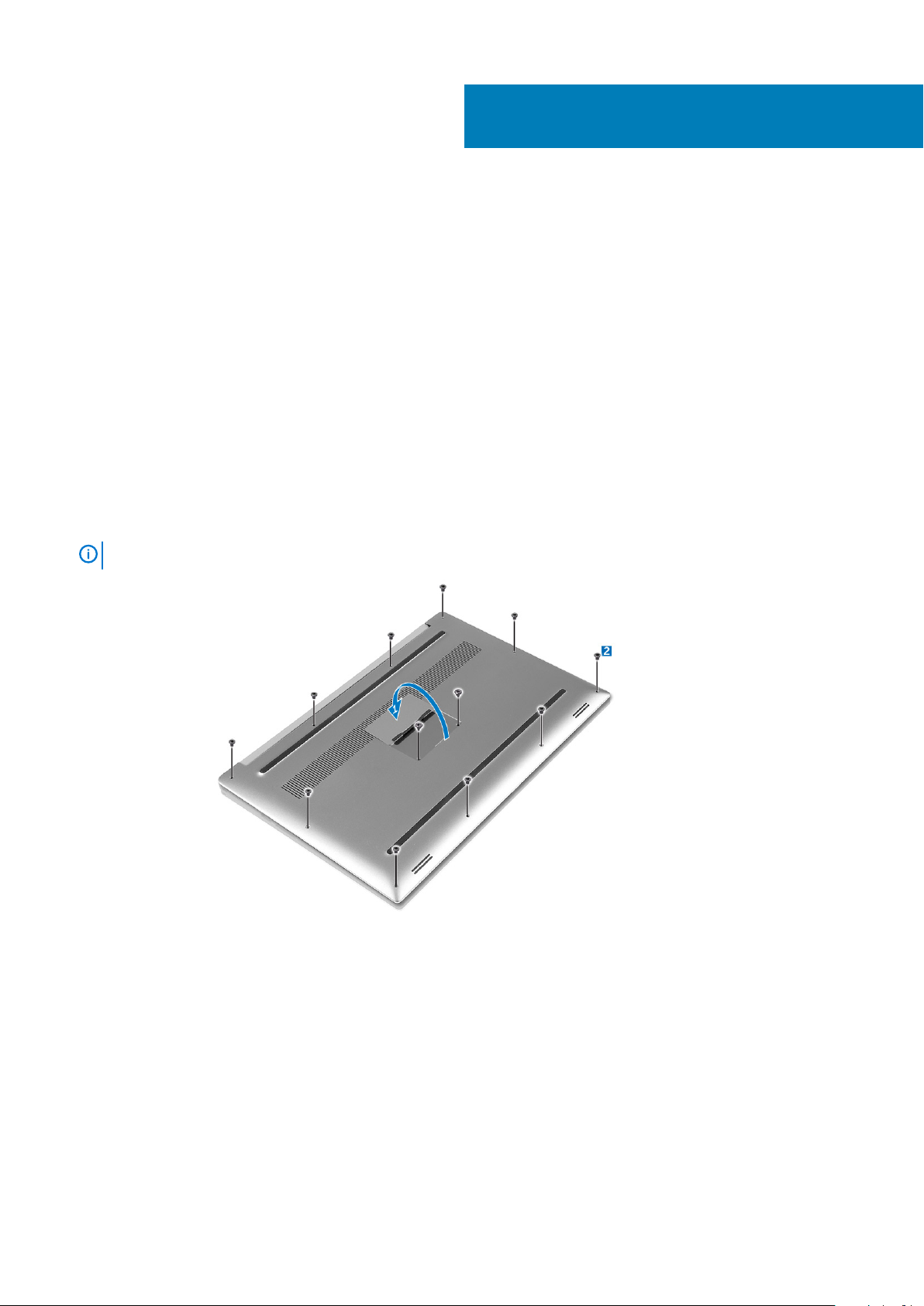
2. Close the display and turn the computer over.
3. Turn the system badge flap over (1) and then remove the screws that secure the base cover to the computer (2).
2
NOTE:
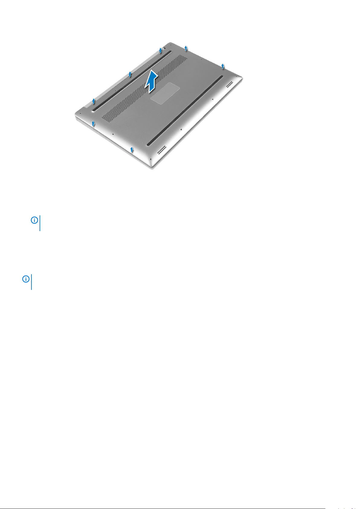
4. Pry the edges base cover and lift it to remove it from computer .
Use a Torx #5 screwdriver for the base screws and a Philips screwdriver for the screws inside the badge flap.
Extracción e instalación de componentes 7
Installing the Base Cover
1. Place the base cover on the computer and snap it in place.
2. Tighten the screws to secure the base cover to the computer.
NOTE:
screws.
3. Turn the system badge flap over and snap it in place.
4. Follow the procedures in After Working Inside Your Computer.
Ensure you use a Torx #5 screwdriver for the base screws and a Philips screwdriver for the system badge
Removing the Battery
NOTE:
the A/C adapter from the system (while the system is turned on) to allow the system to drain the battery.
1. Follow the procedures in Before Working Inside Your Computer.
2. Remove the base cover.
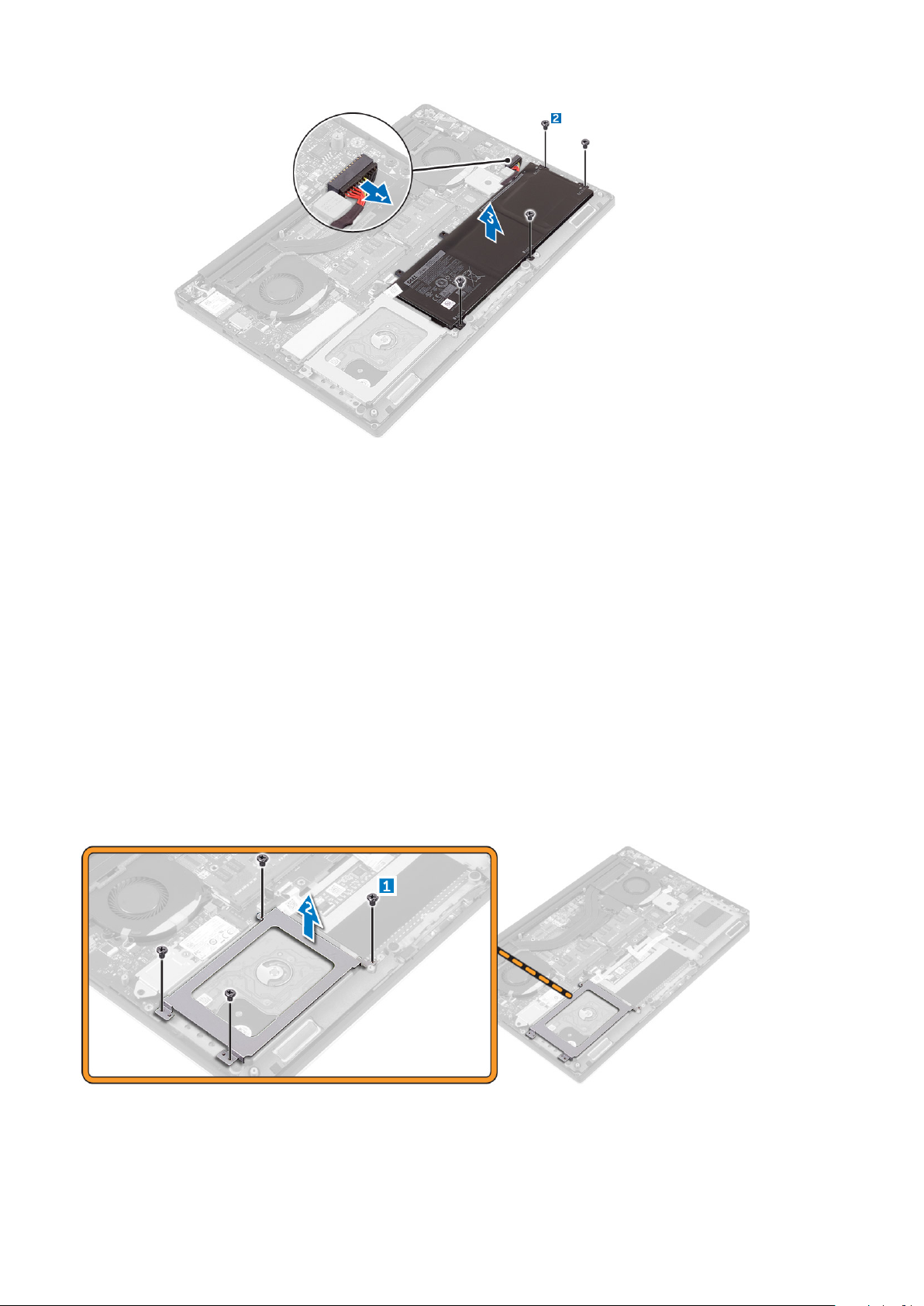
3. Perform the following steps to remove the battery:
a) Disconnect the battery cable from the system board [1].
b) Remove the screws that secure the battery to the computer [2].
c) Lift the battery off the computer [3].
• Do not apply pressure to the surface of the battery
• Do not bend
• Do not use tools of any kind to pry on or against the battery
• If a battery cannot be removed within the constraints above, please contact Dell technical support
Discharge the battery as much as possible before removing from the system. This can be done by disconnecting
8
Extracción e instalación de componentes
Installing the Battery
1. Place and align the battery in the battery bay.
2. Tighten the screws that secure the battery to the computer.
3. Connect the battery cable to the system board.
4. Install the base cover.
5. Follow the procedures in After Working Inside Your Computer.
Removing the Hard Drive
1. Follow the procedures in Before Working Inside Your Computer.
2. Remove the:
a) base cover
b) battery
3. Perform the following steps to remove the hard-drive bracket from the computer:
a) Remove the screws securing the hard-drive bracket to the computer [1].
b) Lift the hard-drive bracket off the computer [2].
4. Perform the following steps to remove the hard-drive:
a) Disconnect the hard-drive cable from the system board [1].
b) Lift the hard drive off the computer [2].
Extracción e instalación de componentes
9
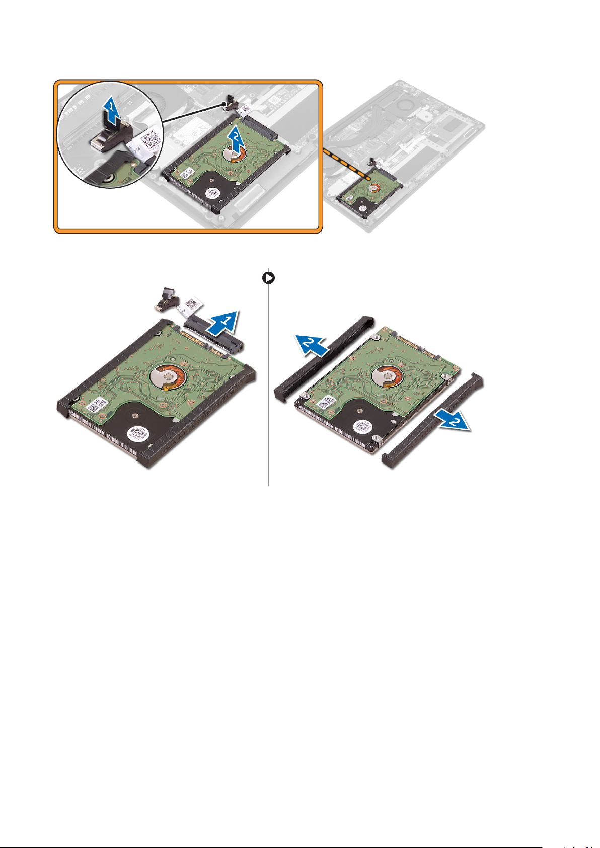
5. Remove the data-cable connector [1] and then slide out the two end brackets [2].
Installing the Hard Drive
1. Replace the hard-drive covers on the hard drive.
2. Connect the hard-drive interposer to the hard-drive assembly.
3. Place the hard-drive assembly on the palm-rest assembly.
4. Connect the hard-drive cable to the system board.
5. Align the screw holes on the hard-drive cage with the screw holes on the hard-drive assembly.
6. Replace the screws that secure the hard-drive cage to the palm-rest assembly.
7. Install the:
a) battery
b) base cover
8. Follow the procedures in After Working Inside Your Computer.
Removing the Solid-State Drive (half-length)
1. Follow the procedures in Before Working Inside Your Computer.
2. Remove the:
a) base cover
b) battery
10
Extracción e instalación de componentes
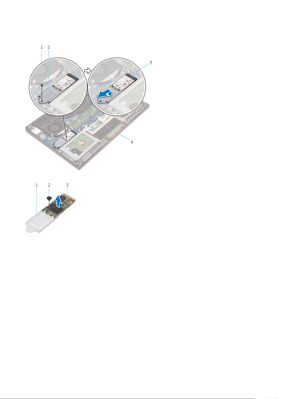
3. Remove the screw that secures the solid-state drive assembly to the system board [1, 2].
4. Lift and slide the solid-state drive assembly from the system board [3].
5. Remove the screw that secures the solid-state drive to the solid-state drive bracket [1, 2, 3].
6. Lift the solid-state drive off the solid-state drive bracket.
Installing the Solid-State Drive (half-length)
1. Align the screw hole on the solid-state drive bracket with the screw hole on the solid-state drive.
2. Replace the screw that secures the solid-state drive to the solid-state drive bracket.
3. Align the notches on the solid-state drive assembly with the tabs in the solid-state drive slot.
4. Slide the solid-state drive assembly at an angle into the solid-state drive slot.
5. Press the other end of the solid-state drive down and replace the screw that secures the solid-state drive to the system board.
6. Install the:
a) battery
b) base cover
7. Follow the procedures in After Working Inside Your Computer.
Removing the Solid-State Drive (full-length)
1. Follow the procedures in Before Working Inside Your Computer
2. Remove the:
a) base cover
b) battery
Extracción e instalación de componentes
11
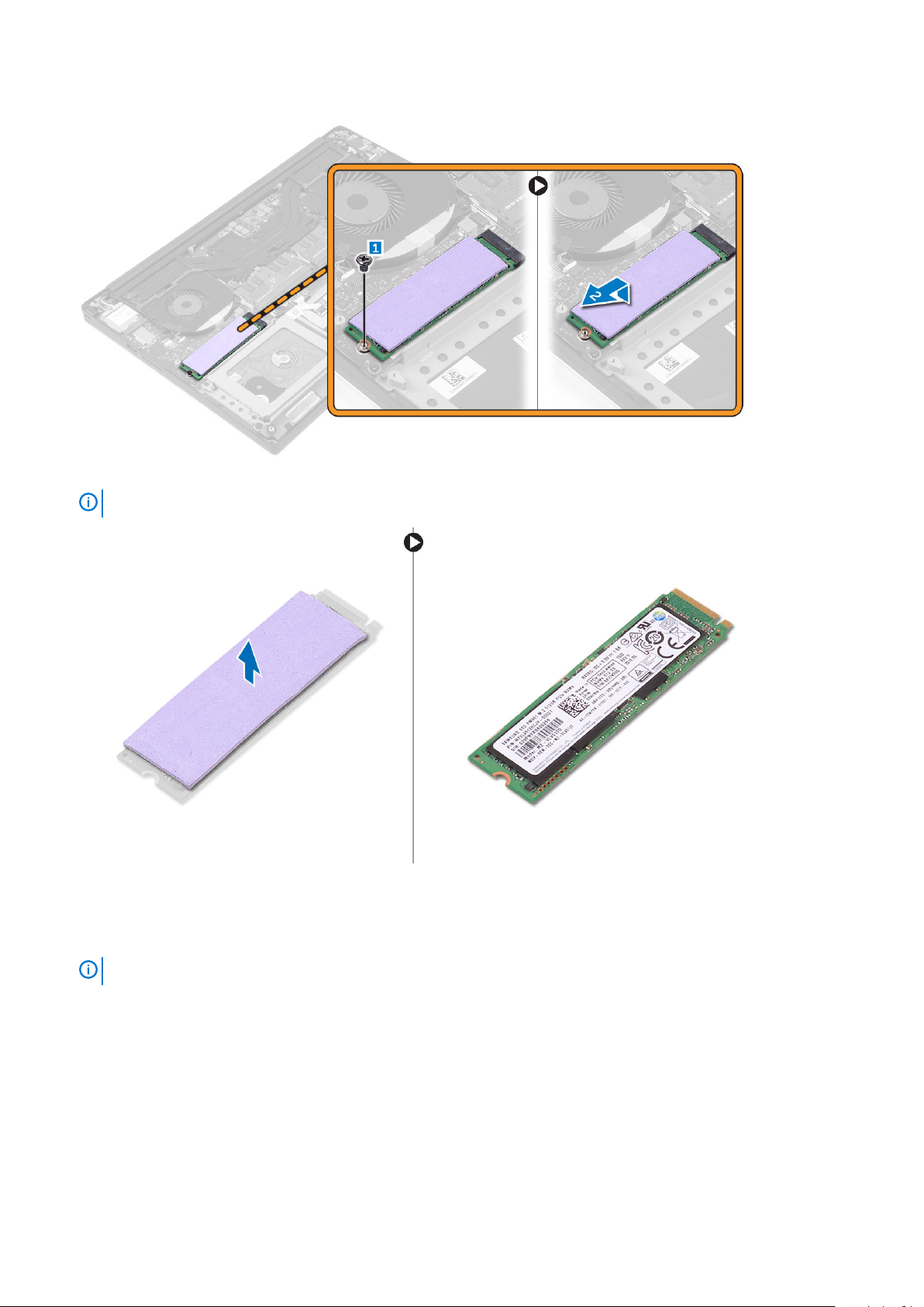
3. Remove the screw that secures the solid-state drive to the system board.
4. Remove the thermal pad from the SSD.
NOTE:
The thermal pad is applicable only for a PCIe SSD card.
Installing the Solid-State Drive (full-length)
1. Adhere the thermal pad to the solid-state drive.
NOTE:
2. Slide the solid-state drive at an angle into the solid-state drive slot.
3. Press the other end of the solid-state drive down and replace the screw that secures the solid-state drive to the system board.
4. Install the:
a) battery
b) base cover
5. Follow the procedures in After Working Inside Your Computer.
12
The thermal pad is applicable only for a PCIe SSD card.
Extracción e instalación de componentes
Removing the Speakers
1. Follow the procedures in Before Working Inside Your Computer.
2. Remove the:
a) base cover
b) battery
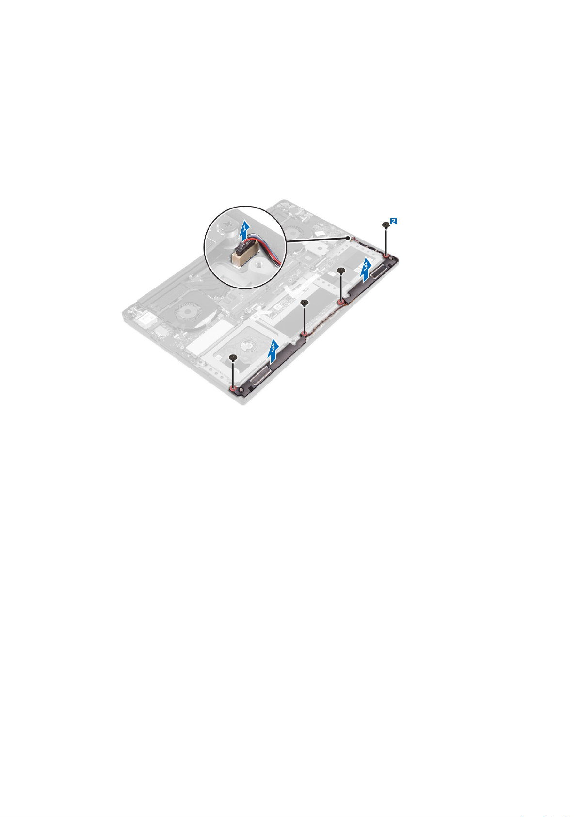
3. Perform the following steps to remove the speaker:
a) Disconnect the speaker cable from the system board [1].
b) Remove the screws that secure the speakers to the computer [2].
c) Lift the speakers, along with the speaker cable, off the computer [3].
Installing the Speakers
1. Using the alignment posts, place the speakers on the palm-rest assembly.
2. Replace the screws that secure the speakers to the palm-rest assembly.
3. Route the speaker cables through the routing guides on the palm-rest assembly.
4. Connect the speaker cable to the system board.
5. Install the:
a) battery
b) base cover
6. Follow the procedures in After Working Inside Your Computer.
Removing the WLAN Card
1. Follow the procedures in Before Working Inside Your Computer.
2. Remove the:
a) base cover
b) battery
3. Perform the following steps to remove the WLAN card:
a) Remove the screw to release the bracket that secures the WLAN card to the computer [1] and lift the bracket away from the
computer [2].
b) Disconnect the antenna cables from the WLAN card [3].
c) Slide and remove the WLAN card from its connector on the board [4].
Extracción e instalación de componentes
13

Installing the WLAN Card
1. Align the notch on the WLAN card with the tab on the WLAN-card connector on the I/O board.
2. Align the bracket which secures the WLAN card to the palmrest assembly.
3. Connect the antenna cables to the WLAN card.
CAUTION:
NOTE: The color of the antenna cables is visible near the tip of the cables. The antenna-cable color scheme for the
WLAN card supported by your computer is as follows:
Table 1. Antenna-Cable Color Scheme for the WLAN Card
Connectors on the WLAN card Antenna-cable color
Main (white triangle) white
Auxiliary (black triangle) black
Multiple input, multiple output (grey triangle) Grey (optional)
4. Tighten the screw to secure the bracket and the WLAN card to the palmrest assembly.
5. Install the:
a) battery
b) base cover
6. Follow the procedures in After Working Inside Your Computer.
To avoid damage to the WLAN card, do not place any cables under it.
Removing the Fans
1. Follow the procedures in Before Working Inside Your Computer.
2. Remove the:
a) base cover
b) battery
3. Perform the following steps to remove the left video-card fan:
a) Un-thread the LVDS cable from its restraints [1] and [2].
b) Disconnect the fan cable from the system board [3]
c) Remove the screws that secure the fan to the computer [4].
d) Lift the fan away from the computer [5].
14
Extracción e instalación de componentes

4. Perform the following steps to remove the right system fan:
a) Un-thread the LVDS cable from its restraints [1].
b) Disconnect the fan cable from the system board [2]
c) Remove the screws that secure the fan to the computer [3].
d) Lift the fan away from the computer [4].
Installing the Fans
1. Perform the following steps to install the system fan:
a) Align the screw holes on the left fan with the screw holes on the palm-rest assembly.
b) Connect the left fan cable to the system board.
c) Route the display cable through the routing guides on the left fan.
d) Replace the screws that secure the left fan to the system board.
e) Connect the right fan cable to the system board.
f) Route the touch-screen cable through the routing guides on the right fan.
g) Adhere the tape that secures the touch-screen cable to the right fan.
h) Connect the display cable to the system board.
i) Replace the screws that secure the right fan to the system board.
2. Follow the procedures in After Working Inside Your Computer.
Extracción e instalación de componentes
15

Removing the Heatsink
1. Follow the procedures in Before Working Inside Your Computer.
2. Remove the:
a) base cover
b) battery
3. Remove the screws that secure the heatsink to the system board.
4. Lift the heatsink off the computer.
Installing the Heatsink
1. Align the screw holes on the heatsink with the screw holes on the system board.
2. Replace the screws to secure the heatsink to the system board.
3. Install the:
a) battery
b) base cover
4. Follow the procedures in After Working Inside Your Computer.
16
Extracción e instalación de componentes

Removing the Memory Module(s)
1. Follow the procedures in Before Working Inside Your Computer.
2. Remove the:
a) base cover
b) battery
3. Pry the securing clips away from the memory module until it pops-up. Remove the memory module from its connector on the system
board.
Installing the Memory Module(s)
1. Insert the memory module into the memory socket.
2. Press the memory module down until it clicks into place.
NOTE:
3. Install the:
a) battery
b) base cover
4. Follow the procedures in After Working Inside Your Computer.
If you do not hear the click, remove the memory module and re-install it.
Removing the System Board
1. Follow the procedures in Before Working Inside Your Computer.
2. Remove the:
a) base cover
b) battery
c) fans
d) heatsink
e) SSD
f) memory modules
NOTE:
BIOS after you replace the system board.
NOTE: Before disconnecting the cables from the system board, note the location of the connectors so that you can
re-connect them correctly after you replace the system board.
Your computer’s Service Tag is located under the system badge flap. You must enter the Service Tag in the
Extracción e instalación de componentes 17

3. Remove the screw securing the metal bracket for the LVDS to the system board [1] and remove the bracket off the computer [2].
Then, disconnect the LVDS cable from the system board [3].
4. Slide out the connector latches to disconnect all the cables from the system board.
5. Perform the following steps to remove the system board from the computer:
a) Remove the screws that secure the system board to the computer [1].
b) Lift the system board off the computer [2].
18
Extracción e instalación de componentes

Installing the System Board
1. Align the system board on the computer.
2. Replace the screws that secure the system board to the palm-rest assembly.
3. Connect the power-adapter port cable, speaker cable, keyboard-control board cable, touch-pad cable, and touch-screen cable to the
system board.
4. Connect the display cable to the system board.
5. Align the screw hole on the display-cable bracket with the screw hole on the system board.
6. Follow the procedures in After Working Inside Your Computer.
Removing the Audio Daughter Board
1. Follow the procedures in Before Working Inside Your Computer.
2. Remove the:
a) base cover
b) battery
c) WLAN card
d) hard drive
e) SSD (half length)
f) SSD (full length)
g) fans
h) heatsink
i) memory modules
j) system board
3. Remove the two screws that secure the audio daughter board to the system board.
Extracción e instalación de componentes
19

a. system board
b. screws
4. Flip the system board over, then lift the audio daughter board from the system board.
a. audio daughter board
Installing the audio daughter board
1. Align the screw holes on the audio daughter board with the screw holes on the system board.
2. Flip the system board over, then replace the screws that secure the audio daughter board to the system board.
3. Install the:
a) system board
b) memory modules
c) heat-sink assembly
d) fans
e) solid-state drive (half-length)
f) solid-state drive (full-length)
g) hard drive
h) wireless card
i) battery
20
Extracción e instalación de componentes

j) base cover
4. Follow the procedures in After Working Inside Your Computer.
Removing the Keyboard
1. Follow the procedures in Before Working Inside Your Computer.
2. Remove the:
a) base cover
b) battery
c) fans
d) heatsink
e) SSD
f) memory modules
g) system board
3. Perform the following steps to disconnect the keyboard and backlight connectors from the computer.
a) Lift up the connector lock [1] and the disconnect the cables from the connectors [2].
b) Peel back the screw shields [3].
4. Un-route the LVDS cable [1] and then remove the screws that secure the keyboard to the computer [2].
5. Lift and remove the keyboard from the computer.
Extracción e instalación de componentes
21

Installing the Keyboard
1. Adhere the Mylar to the keyboard.
2. Align the screw holes on the keyboard with the screw holes on the palm-rest assembly.
3. Replace the screws that secure the keyboard to the palm-rest assembly.
4. Adhere the Mylar to the screws that secure the keyboard to the palm-rest assembly.
5. Connect the keyboard cable and keyboard-backlight cable to the keyboard-controls board.
6. Install the:
a) system board
b) hard drive
c) base cover
7. Follow the procedures in After Working Inside Your Computer.
Removing the Display Assembly
1. Follow the procedures in Before Working Inside Your Computer.
2. Remove the:
a) base cover
b) battery
3. Perform the following steps:
a) Disconnect the left LVDS cable [1].
b) Remove the screw securing the metal bracket [2] and lift the bracket off the computer [3].
c) Disconnect the right LVDS cable from the system board [4].
22
Extracción e instalación de componentes

4. Place the computer at the edge of a table as shown and remove the screws [1] securing the display assembly to the computer. Then,
lift the display assembly off the computer [2].
Installing the Display Assembly
1. Place the palm-rest assembly at the edge of the table with the speakers facing away from the edge.
2. Align the screw holes on the palm-rest assembly with the screw holes on the display hinges.
Extracción e instalación de componentes
23

3. Replace the screws that secure the display hinges to the palm-rest assembly.
4. Adhere the tape and route the touch-screen cable through the routing guides on the fan.
5. Connect the touch-screen cable and display cable to the system board.
6. Replace the screw that secures the display-cable bracket to the system board.
7. Follow the procedures in After Working Inside Your Computer.
Removing the DC-in Connector
1. Follow the procedures in Before Working Inside Your Computer.
2. Remove the:
a) base cover
b) battery
3. Perform the following steps to remove the I/O board:
a) Disconnect the DC-in cable from the system board [1].
b) Remove the screw that secures the DC-in cable to the computer.
c) Remove the DC-in connector from the computer.
Installing the DC-in Adapter Port
1. Place the DC-in adapter port into the slot on the palm-rest assembly.
2. Route the power-adapter port cable through its routing guides on the palm-rest assembly.
3. Replace the screw that secures the power-adapter port to the palm-rest assembly.
4. Connect the power-adapter port cable to the system board.
5. Install the:
a) battery
b) base cover
6. Follow the procedures in After Working Inside Your Computer.
Removing the antenna cover
1. Follow the procedures in Before Working Inside Your Computer.
2. Remove the:
a) base cover
b) battery
c) WLAN Card
24
Extracción e instalación de componentes

d) display assembly
3. Carefully turn the display hinges at an angle.
Figure 1. Turning the display hinge
a. display assembly
b. display hinges (2)
4. Slide and lift the antenna cover away from the display assembly.
Figure 2. Removing the antenna cover
a. display assembly
b. antenna cover
Installing the antenna cover
1. Replace the antenna cover on the display assembly.
2. Turn the display hinges to the normal position.
3. Install the:
a) display assembly
b) wireless card
c) battery
d) base cover
4. Follow the procedures in After Working Inside Your Computer.
Extracción e instalación de componentes
25

Removing the display hinges
1. Follow the procedures in Before Working Inside Your Computer.
2. Remove the:
a) base cover
b) battery
c) WLAN Card
d) display assembly
e) antenna cover
3. Peel off the tape to access the screws on the display hinges.
a. tape
b. display hinges (2)
4. Remove the screws that secure the display hinges to the display assembly.
5. Carefully lift the display hinges off the display assembly.
a. screws (6)
b. display hinges (2)
Installing the display hinges
1. Align the screw holes on the display hinges with the screw holes on the display assembly.
26
Extracción e instalación de componentes

2. Replace the screws that secure the display hinges to the display assembly.
3. Adhere the tape to the display hinges.
4. Install the:
a) antenna cover
b) display assembly
c) wireless card
d) battery
e) base cover
5. Follow the procedures in After Working Inside Your Computer.
Removing the antenna module
1. Follow the procedures in Before Working Inside Your Computer.
2. Remove the:
a) base cover
b) battery
c) wireless card
d) display assembly
e) antenna cover
f) display hinges
3. Peel the tape that covers the antenna cables.
4. Remove the screws that secure the antenna module to the display assembly.
5. Lift the antenna module away from the display assembly.
tape 2. antenna cable
1.
3. screws (4) 4. antenna module
5. display assembly
Installing the antenna module
1. Align the screw holes on the antenna module with the screw holes on the display assembly.
2. Replace the screws that secure the antenna module to the display assembly.
3. Adhere the tape that covers the antenna cable.
4. Install the:
a) display hinges
Extracción e instalación de componentes
27

b) antenna cover
c) display assembly
d) wireless card
e) battery
f) base cover
5. Follow the procedures in After Working Inside Your Computer.
Removing the palm-rest assembly
1. Follow the procedures in Before Working Inside Your Computer.
2. Remove the:
a) base cover
b) battery
c) memory modules
d) Follow the procedure from step 1 to step 4 in “Removing the hard drive
e) wireless card
f) speakers
g) heat-sink
h) fans
i) display assembly
j) power-adapter port
k) system board
l) keyboard
After performing the steps in the prerequisites we are left with the palm-rest assembly.
a. palm-rest assembly
Installing the palm-rest assembly
1. Place the palm-rest assembly on a clean and flat surface.
2. Install the:
a) keyboard
b) system board
c) power-adapter port
d) display assembly
e) fans
f) heat-sink assembly
g) speakers
h) wireless card
i) Follow the procedure from step 3 to step 6 in “Replacing the hard drive”.
28
Extracción e instalación de componentes

j) memory modules
k) battery
l) base cover
3. Follow the procedures in After Working Inside Your Computer.
Extracción e instalación de componentes 29

3
System Setup (Configuración del sistema)
System Setup (Configuración del sistema) le permite administrar el hardware de la tabletacomputadoralaptop y especificar las opciones de
nivel de BIOS. En System Setup (Configuración del sistema), puede:
• Modificar la configuración de la NVRAM después de añadir o eliminar hardware.
• Ver la configuración de hardware del sistema.
• Habilitar o deshabilitar los dispositivos integrados.
• Definir umbrales de administración de energía y de rendimiento.
• Administrar la seguridad del equipo.
Temas:
• Secuencia de arranque
• Teclas de navegación
• System Setup Options
• Actualización de BIOS en Windows
• Contraseña del sistema y de configuración
Secuencia de arranque
La secuencia de arranque le permite omitir el orden de dispositivos de arranque definido en la configuración del sistema y arrancar
directamente desde un dispositivo específico (por ejemplo, la unidad óptica o la unidad de disco duro). Durante la autoprueba de encendido
(POST), cuando aparezca el logotipo de Dell, podrá hacer lo siguiente:
• Acceder al programa de configuración del sistema al presionar la tecla F2
• Activar el menú de inicio de una vez al presionar la tecla F12
El menú de arranque de una vez muestra los dispositivos desde los que puede arrancar, incluida la opción de diagnóstico. Las opciones del
menú de arranque son las siguientes:
• Unidad extraíble (si está disponible)
• Unidad STXXXX
NOTA:
• Unidad óptica (si está disponible)
• Diagnóstico
NOTA:
La pantalla de secuencia de inicio también muestra la opción de acceso a la pantalla de la configuración del sistema.
XXX denota el número de la unidad SATA.
Al elegir Diagnósticos, aparecerá la pantalla Diagnósticos de ePSA.
Teclas de navegación
NOTA:
aplican hasta que se reinicia el sistema.
Teclas Navegación
Para la mayoría de las opciones de configuración del sistema, se registran los cambios efectuados, pero no se
Flecha hacia arriba Se desplaza al campo anterior.
Flecha hacia abajo Se desplaza al campo siguiente.
Intro Permite introducir un valor en el campo seleccionado, si se puede, o seguir el vínculo del campo.
Barra espaciadora Amplía o contrae una lista desplegable, si procede.
Lengüeta Se desplaza a la siguiente área de enfoque.
NOTA: Solo para el explorador de gráficos estándar.
30 System Setup (Configuración del sistema)

Teclas Navegación
Esc Cambia a la página anterior hasta visualizar la pantalla principal. Si presiona la tecla Esc en la pantalla principal,
aparecerá un mensaje que le solicitará guardar los cambios y reiniciar el sistema.
System Setup Options
NOTE: Depending on your computer and its installed devices, the items listed in this section may or may not appear.
Table 2. Main
Option Description
System Time/Date Allows you to set the date and time.
BIOS Version Displays the BIOS version.
Product Name Displays the product name.
Dell Precision M3800 (Default Setting)
Service Tag Displays the service tag.
Asset Tag Displays the asset tag.
None (Default Setting)
CPU Type Displays the CPU type.
CPU Speed Displays the CPU speed.
CPU ID Displays the CPU ID.
CPU Cache Displays the sizes of the CPU caches.
Fixed HDD Displays the type and size of the HDD.
WDC WD10SPCX-75HWSTO (1000 GB) (Default Setting)
mSATA Device Displays the type and size of the mSATA device.
AC Adapter Type Displays the type of the AC adapter.
None (Default Setting)
System Memory Displays the size of the system memory.
Extended Memory Displays the size of the extended memory.
Memory Speed Displays the speed of the memory.
Keyboard Type Displays the type of keyboard.
Backlite (Default Setting)
Table 3. Advanced
Option Description
Intel (R) SpeedStep (TM) Allows you to enable or disable the Intel (R) SpeedStep (TM) feature.
Enabled (Default Setting)
Virtualization This option specifies whether a Virtual Machine Monitor (VMM) can utilize the additional hardware
capabilities provided by Intel Virtualization technology. Allows you to enable or disable the
Virtualization feature.
Enabled (Default Setting)
USB Emulation Allows you to enable or disable the USB Emulation feature.
Enabled (Default Setting)
USB PowerShare Allows you to enable or disable the USB PowerShare feature.
System Setup (Configuración del sistema) 31

Option Description
Enabled (Default Setting)
USB Wake Support This option allows you to enable USB devices to wake the system from Standby.
Disable(Default Setting)
SATA Operation Displays the SATA Operation information.
Adapter Warnings Allows you to enable or disable the adapter warnings feature.
Multimedia Key Behaviour
Battery Health Displays the battery health information.
Battery Charge Configuration
Miscellaneous Devices Allows you enable or disable the various on board devices. The options are:
Table 4. Security
Option Description
Unlock Setup Status
Admin Password Status Displays the status of the admin password.
Function Key (Default Setting)
Adaptive (Default Setting)
• External USB Ports - Enabled (Default Setting)
• USB Debug - Disabled (Default Setting)
Unlocked (Default Setting)
Default Setting: Not set
System Password Status Displays the status of the system password.
Default Setting: Not set
HDD Password Status Displays the status of the system password.
Default Setting: Not set
Asset Tag Allows you to set the asset tag.
Admin Password Allows you to set, change, or delete the administrator (admin) password.
NOTE: You must set the admin password before you set the system or hard drive
password.
NOTE: Successful password changes take effect immediately.
NOTE: Deleting the admin password automatically deletes the system password
and the hard drive password.
NOTE: Successful password changes take effect immediately.
System Password Allows you to set, change or delete the system password.
NOTE: Successful password changes take effect immediately.
HDD Password Allows you to set, change or delete the administrator password.
Password Change Allows you to enable or disable permissions to set a System password and a Hard Drive
password when the admin password is set.
Default Setting: Permitted
Computrace Allows you to activate or disable the optional Computrace software The options are:
• Deactivate (Default Setting)
• Activate
NOTE: The Activate and Disable options will permanently activate or disable the
feature and no further changes will be allowed.
32 System Setup (Configuración del sistema)

Option Description
TPM Security This option lets you control whether the Trusted Platform Module (TPM) in the system is
enabled and visible to the operating system. When disabled the BIOS will not turn On the TPM
During POST. The TPM will be non-functional and invisible to the operating system. When
enabled, the BIOS will turn On the TPM during POST so that it can be used by the operating
system. This option is
NOTE: Disabling this option does not change any settings you may have made to
the TPM, nor does it delete or change any information or keys you may have
stored there. It simply turns Off the TPM so that it cannot be used. When you reenable this option, the TPM will function exactly as it did before it was disabled.
NOTE: Changes to this option take effect immediately.
Table 5. Boot
Option Description
Boot List Option
Secure Boot This option enables or disables the Secure Boot feature.
Load Legacy Option ROM This option enables or disables the Load Legacy Option ROM feature.
Default Setting: Legacy
• Disabled (Default Setting) - Windows 7
• Enabled - Windows 8.1
• Enabled (Default Setting) - Windows 7
• Disabled - Windows 8.1
Enable by default.
Set Boot Priority Allows you to change the order in which the computer attempts to find an operating system:
• 1 st Boot Priority [ CD/DVD/CD-RW Drive]
• 2nd Boot Priority [Network]
• 3rd Boot Priority [mini SSD]
• 4th Boot Priority [USB Storage Device
• 5th Boot Priority [Hard Drive]
• 6th Boot Priority [Diskette Drive]
Table 6. Exit
Option Description
Save Changes and Reset Allows you to save the changes you made.
Discard Changes and Reset Allows you to discard the changes you made.
Restore Defaults Allows you to restore the default options.
Discard Changes Allows you to discard the changes you made.
Save Changes Allows you to save the changes you made.
Actualización de BIOS en Windows
Se recomienda actualizar el BIOS (configuración del sistema) si se sustituye la placa base o si hay una actualización disponible. Para
laptops, asegúrese de que la batería de su computadora esté totalmente cargada y conectada a una toma de corriente.
NOTA:
continuación, debe volver a activarse después de que se complete la actualización de BIOS.
1. Reinicie la computadora.
2. Vaya a Dell.com/support.
• Escriba la Service Tag (etiqueta de servicio) o Express Service Code (código de servicio rápido) y haga clic en Submit
• Haga clic en Detectar el producto y siga las instrucciones que aparecen en la pantalla.
Si BitLocker está activado, se debe estar suspendido antes de la actualización de BIOS del sistema y, a
(enviar).
System Setup (Configuración del sistema)
33

3. Si no puede detectar o encontrar la etiqueta de servicio, haga clic en Elegir entre todos los productos
4. Elija la categoría Products (Productos) de la lista.
NOTA: Seleccione la categoría adecuada para llegar a la página del producto.
Seleccione el modelo del equipo y aparecerá la página Product Support (Soporte técnico del producto) de su equipo.
5.
6. Haga clic en Get drivers (Obtener controladores) y en Drivers and Downloads (Controladores y descargas).
Se abre la sección de controladores y descargas.
7. Haga clic en Buscarlo yo mismo.
8. Haga clic en BIOS para ver las versiones del BIOS.
9. Identifique la última versión de archivo BIOS y haga clic en Download (Descargar).
10. Seleccione su método de descarga preferido en la ventana Please select your download method below (Seleccione el método
de descarga a continuación) y haga clic en Download File (Descargar archivo).
Aparecerá la ventana File Download (Descarga de archivos).
11. Haga clic en Save (Guardar) para guardar el archivo en su equipo.
12. Haga clic en Run (ejecutar) para instalar las configuraciones del BIOS actualizado en su equipo.
Siga las instrucciones que aparecen en pantalla.
NOTA: Se recomienda no actualizar la versión del BIOS a más de 3 revisiones. Por ejemplo, si desea actualizar el BIOS
desde 1.0 a 7.0, instale la versión 4.0 en primer lugar y, a continuación, instale la versión 7.0 .
Contraseña del sistema y de configuración
Puede crear una contraseña del sistema y una contraseña de configuración para proteger su equipo.
Tipo de
Descripción
contraseña
System Password Es la contraseña que debe introducir para iniciar sesión en el sistema.
Setup password
(Contraseña de
configuración)
PRECAUCIÓN: Las funciones de contraseña ofrecen un nivel básico de seguridad para los datos del equipo.
PRECAUCIÓN: Cualquier persona puede tener acceso a los datos almacenados en el equipo si no se bloquea y se deja
desprotegido.
NOTA: La computadora se entrega con la función de contraseña de configuración y de sistema desactivada.
Es la contraseña que debe introducir para acceder y realizar cambios a la configuración de BIOS del equipo.
Asignación de contraseña del sistema y de configuración
Puede asignar una nueva contraseña del sistema solo cuando el estado se encuentra en Not Set (No establecido).
Para acceder a System Setup (Configuración del sistema), presione <F2> inmediatamente después del encendido o el reinicio.
1. En la pantalla System BIOS (BIOS del sistema) o System Setup (Configuración del sistema), seleccione Security
(Seguridad) y presione <Intro>.
Aparece la pantalla Security (Seguridad).
2. Seleccione System Password (Contraseña del sistema) y cree una contraseña en el campo Enter the new password
(Introduzca la nueva contraseña).
Utilice las siguientes pautas para asignar la contraseña del sistema:
• Una contraseña puede tener hasta 32 caracteres.
• La contraseña puede contener números del 0 al 9.
• Solo se permiten letras en minúsculas. Las mayúsculas no están permitidas.
• Solo se permiten los siguientes caracteres especiales: espacio, (”), (+), (,), (-), (.), (/), (;), ([), (\), (]), (`).
3. Introduzca la contraseña del sistema que especificó anteriormente en el campo Confirm new password (Confirmar nueva
contraseña) y haga clic en OK (Aceptar).
4. Presione Esc y aparecerá un mensaje para que guarde los cambios.
34
System Setup (Configuración del sistema)

5. Presione Y para guardar los cambios.
El equipo se reiniciará.
Eliminación o modificación de una contraseña del sistema y de configuración existente
Asegúrese de que Password Status (Estado de la contraseña ) esté Unlocked (Desbloqueado) en System Setup (Configuración del
sistema), antes de intentar eliminar o modificar la contraseña del sistema o de configuración existente. No se puede eliminar ni modificar
una contraseña existente del sistema o de configuración si
Para acceder a la Configuración del sistema, presione F2 inmediatamente después del encendido o el reinicio.
1. En la pantalla System BIOS (BIOS del sistema) o System Setup (Configuración del sistema), seleccione System Security
(Seguridad del sistema) y presione Intro.
Aparecerá la ventana System Security (Seguridad del sistema).
2. En la pantalla System Security (Seguridad del sistema), compruebe que la opción Password Status (Estado de la contraseña)
está en modo Unlocked (Desbloqueado).
3. Seleccione System Password (Contraseña del sistema), modifique o elimine la contraseña del sistema existente y presione Intro o
Tab.
4. Seleccione Setup Password (Contraseña de configuración), modifique o elimine la contraseña de configuración existente y
presione Intro o Tab.
NOTA: Si cambia la contraseña del sistema o de configuración, introduzca la nueva contraseña cuando se lo soliciten.
Si elimina la contraseña del sistema o de configuración, confirme la eliminación cuando se lo soliciten.
5. Presione Esc y aparecerá un mensaje para que guarde los cambios.
6. Presione "Y" para guardar los cambios y salir de System Setup (Configuración del sistema).
El equipo se reiniciará.
Password Status (Estado de la contraseña) está en Locked (Bloqueado).
System Setup (Configuración del sistema)
35

4
Diagnóstico
Si tiene un problema con el equipo, ejecute el diagnóstico de ePSA antes de ponerse en contacto con Dell para recibir asistencia técnica. El
propósito de ejecutar el diagnóstico es probar el hardware del equipo sin la ayuda de equipo adicional y sin riesgo de perder datos. Si no
puede corregir el problema, el personal de servicio y asistencia puede utilizar los resultados de las pruebas de diagnóstico para ayudarlo a
resolver el problema.
Temas:
• Diagnósticos Enhanced Pre-boot System Assessment (Evaluación del sistema de preinicio ePSA)
• Device Status Light
Diagnósticos Enhanced Pre-boot System Assessment (Evaluación del sistema de preinicio ePSA)
Los diagnósticos de ePSA (también conocidos como diagnósticos del sistema) realizan una revisión completa de su hardware. El ePSA
cuenta con el BIOS incorporado y es activado internamente por el BIOS. Los diagnósticos incorporados del sistema ofrecen un conjunto de
opciones para determinados dispositivos o grupos de dispositivos, que le permiten:
• Ejecutar pruebas automáticamente o en modo interactivo
• Repetir las pruebas
• Visualizar o guardar los resultados de las pruebas
• Ejecutar pruebas exhaustivas para introducir pruebas adicionales que ofrezcan más información sobre los dispositivos que han
presentado errores
• Ver mensajes de estado que indican si las pruebas se han completado correctamente
• Ver mensajes de error que informan de los problemas que se han encontrado durante las pruebas
PRECAUCIÓN:
computadoras, es posible que se obtengan mensajes de error o resultados no válidos.
NOTA: Algunas pruebas para determinados dispositivos requieren de la interacción con el usuario. Siempre asegúrese de
estar presente en la terminal del equipo cuando se estén realizando las pruebas de diagnóstico.
Utilizar los diagnósticos del sistema para probar sólo su computadora. Si utiliza este programa con otras
Device Status Light
Table 7.
Icon Description
Turns on when you turn on the computer.
36 Diagnóstico

Technical Specifications
NOTE: Offerings may vary by region. For more information regarding the configuration of your computer, click Start
(Start icon) > Help and Support, and then select the option to view information about your computer.
Table 8. System Information
Feature Specification
System Chipset Mobile Intel HM170 Express Chipset / Intel CM236
DMA Channels two VT-d DMA remap engines
Interrupt Levels Intel 64 and IA-32 Architecture
BIOS Chip (NVRAM) 8 MB
Table 9. Processor
Feature Specification
Processor type 6th Generation Intel Core i3/ 6th Generation Intel Quad Core i5/ 6th Generation
Intel Quad Core i7
L1 cache up to 256 KB cache depending on processor type
L2 cache up to 1024 KB cache depending on processor type
L3 cache up to 6144 KB cache depending on processor type
5
Table 10. Memory
Feature Specification
Type DDR4
Speed 2133 MHz
Connectors 2 SoDIMM Sockets
Capacity 8 GB, 16 GB, and 32GB
Minimum Memory 8 GB
Maximum memory 32 GB
Table 11. Video
Feature Specification
Type
Discrete NVIDIA GeForce GTX 960M
Integrated Intel HD Graphics 530
Data bus PCIE x16, Gen3
Memory
Discrete Up to 2 GB GDDR5
Integrated Shared system memory
Technical Specifications 37

Table 12. Audio
Feature Specification
Integrated dual-channel High-Definition audio
Table 13. Communication
Feature Specification
Network adapter Ethernet via USB-to-Ethernet Dongle provided in box.
NOTE: No RJ45 (10/100/1000Base-T, IPv6) provided.
Wireless
Table 14. Ports and Connectors
Feature Specification
Audio
USB 3.0
Video
Memory card reader SD 4.0
Table 15. Display
Feature Specification
Type 1920 x 1080 FHD
Size 15.6 inches FHD
• Wi-Fi 802.11ac
• Wi-Fi 802.11a/g/n
• Bluetooth 4.1
• Intel WiDi (optional)
• One headset port (headphone and microphone combo)
• two USB 3.0 ports with PowerShare
• One Thunderbolt 3 port with PowerShare (USB-C)
• one HDMI 1.4
3840 x 2160 UltraHD
15.6 inches UltraHD
Dimensions:
Height 194.50 mm (7.66 in)
Width 345.60 mm (13.61 in)
Diagonal 396.52 mm (15.61 in)
Active area (X/Y) 194.50 mm (7.66 in) x 345.60 mm (13.61 in) x 396.52 mm (15.61 in)
Maximum resolution 1920 X 1080 pixels / 3840 X 2160 pixels
Maximum Brightness 400 nits
Operating angle 0° (closed) to 135°
Refresh rate 60 Hz
Minimum viewing angles:
Horizontal 80/80
Vertical 80/80
38 Technical Specifications

Table 16. Keyboard
Feature Specification
Number of keys
Layout QWERTY/AZERTY/Kanji
Table 17. Touchpad
Feature Specification
Active Area:
X-axis 105 mm
Y-axis 80 mm
Table 18. Camera
Feature Specification
Type HD Camera / Digital Array Microphone
Still Resolution 0.92 megapixels (Maximum)
Video Resolution 1280 x 720 pixels (HD) at 30 frames per second (Maximum)
Diagonal 74 degrees
• United States: 80 keys
• United Kingdom: 81 keys
• Brazil: 81 keys
• Japan: 84 keys
Table 19. Storage
Feature Specification
Storage:
Storage Interface SATA 3 Gbps
SATA 6 Gbps
Drives configurations:
Hard Drives (optional) one internal 2.5 inch SATA HDD (supports Intel Smart Response Technology)
Solid State Drives (optional) one Solid State Drive (SSD), with Intel Cache support
Size: 512 GB and 1 TB
Table 20. Battery
Feature Specification
Type Li-polymer 3-cell (56 Whr) / 6-cell (84 Whr)
Dimensions :
56 Whr :
Depth 223.20 mm (8.79 in)
Height 7.20 mm (0.28 in)
Width 71.80 mm (2.83 in)
Weight 0.54 lb (0.24 kg)
84 Whr :
Depth 330.50 mm (13.01 in)
Height 7.20 mm (0.28 in)
Width 71.80 mm (2.83 in)
Technical Specifications 39

Feature Specification
Weight 0.76 lb (0.34 kg)
Voltage 11.4 V
Life span 300 discharge/charge cycles
Temperature range:
Operating (approximate)
Non-operating –40 °C to 65 °C (–40 °F to 149 °F)
Coin-cell battery ML1220
Table 21. AC Adapter
Feature Specification
Input voltage 100 VAC to 240 VAC
Input current (maximum) 1.80 A
Input frequency 50 Hz to 60 Hz
Output power 130 W
Output current 6.67 A
Rated output voltage 19.50 VDC
Dimensions:
Height 22 mm (0.86 inches)
Width 66 mm (2.59 inches)
Depth 143 mm (5.62 inches)
Temperature range:
Operating 0 °C to 40 °C (32 °F to 104 °F)
Non Operating –40 °C to 70 °C (–40 °F to 158 °F)
• Charge : 0 °C to 50 °C (32 °F to 158 °F)
• Discharge: 0 °C to 70 °C (32 °F to 122 °F)
• Operating: 0 °C to 35 °C (32 °F to 95 °F)
Table 22. Physical Dimensions
Physical Specification
Height: 17 mm (0.66 in)
Width 357 mm (14.06 in)
Depth 235 mm (9.27 in)
Weight (Minimum) 2 kg (4.41 lb)
Table 23. Environmental
Feature Specification
Temperature range:
Operating 0 °C to 40 °C (32 °F to 104°F)
Storage –40 °C to 70 °C (–40 °F to 158 °F)
Relative humidity (maximum):
Operating 10 % to 90 % (non-condensing)
Storage 10 % to 95 % (non-condensing)
Maximum vibration:
40 Technical Specifications

Feature Specification
Operating 0.66 GRMS, 2 Hz - 600 Hz
Storage 1.3 GRMS, 2 Hz - 600 Hz
Maximum shock:
Operating 110 G, 2 ms
Non-operating 160 G, 2 ms
Altitude:
Operating
Storage 15.2 m to 10,668 m (–50 ft to 35,000 ft)
Airborne contaminant level G1 as defined by ISA-S71.04-1985
–15.2 m to 30482000 m (–50 to 10,0006560 ft)
Technical Specifications 41

Cómo ponerse en contacto con Dell
NOTA: Si no tiene una conexión a Internet activa, puede encontrar información de contacto en su factura de compra, en
su albarán de entrega, en su recibo o en el catálogo de productos Dell.
Dell proporciona varias opciones de servicio y asistencia en línea y por teléfono. La disponibilidad varía según el país y el producto y es
posible que algunos de los servicios no estén disponibles en su área. Si desea ponerse en contacto con Dell para tratar cuestiones
relacionadas con las ventas, la asistencia técnica o el servicio de atención al cliente:
1. Vaya a Dell.com/support.
2. Seleccione la categoría de soporte.
3. Seleccione su país o región en la lista desplegable Elija un país o región que aparece al final de la página.
4. Seleccione el enlace de servicio o asistencia apropiado en función de sus necesidades.
6
42 Cómo ponerse en contacto con Dell
 Loading...