


Dell Precision 5510
Owner's Manual
Regulatory Model: P56F
Regulatory Type: P56F001

メモ、注意、警告
メモ: 製品を使いやすくするための重要な情報を説明しています。
注意: ハードウェアの損傷やデータの損失の可能性を示し、その危険を回避するための方法を説明しています。
警告: 物的損害、けが、または死亡の原因となる可能性があることを示しています。
著作権 © 2017 すべての著作権は Dell Inc. またはその子会社にあります。 Dell、EMC、およびその他の商標は、Dell Inc. またはそ
の子会社の商標です。その他の商標は、それぞれの所有者の商標である場合があります。
2015 - 10
Rev. A00

Contents
1 コンピュータ内部の作業................................................................................................................. 5
コンピュータの電源を切る................................................................................................................................................ 5
コンピュータ内部の作業を始める前に........................................................................................................................... 5
コンピュータ内部の作業を終えた後に........................................................................................................................... 5
2 コンポーネントの取り外しと取り付け.............................................................................................. 7
奨励するツール..................................................................................................................................................................... 7
ベースカバーの取り外し..................................................................................................................................................... 7
ベースカバーの取り付け..................................................................................................................................................... 8
Removing the Battery...........................................................................................................................................................8
バッテリーの取り付け........................................................................................................................................................ 9
ハードドライブの取り外し................................................................................................................................................ 9
ハードドライブの取り付け...............................................................................................................................................10
Removing the Solid-State Drive (half-length)................................................................................................................. 10
Installing the Solid-State Drive (half-length).....................................................................................................................11
Removing the Solid-State Drive (full-length)....................................................................................................................11
Installing the Solid-State Drive (full-length)..................................................................................................................... 12
スピーカーの取り外し ...................................................................................................................................................... 13
スピーカーの取り付け........................................................................................................................................................13
WLAN カードの取り外し...................................................................................................................................................13
WLAN カードの取り付け...................................................................................................................................................14
ファンの取り外し ..............................................................................................................................................................14
ファンの取り付け...............................................................................................................................................................15
ヒートシンクの取り外し...................................................................................................................................................16
ヒートシンクの取り付け...................................................................................................................................................16
メモリモジュールの取り外し...........................................................................................................................................17
メモリモジュールの取り付け...........................................................................................................................................17
システム基板の取り外し.................................................................................................................................................. 17
システム基板の取り付け.................................................................................................................................................. 19
Removing the Audio Daughter Board................................................................................................................................19
Installing the audio daughter board...................................................................................................................................20
キーボードの取り外し........................................................................................................................................................21
キーボードの取り付け....................................................................................................................................................... 22
ディスプレイアセンブリの取り外し.............................................................................................................................22
ディスプレイアセンブリの取り付け.............................................................................................................................23
DC 入力コネクタの取り外し...........................................................................................................................................24
DC 入力アダプタポートの取り付け............................................................................................................................... 24
Removing the antenna cover.............................................................................................................................................24
Installing the antenna cover............................................................................................................................................... 25
Removing the display hinges..............................................................................................................................................26
Installing the display hinges................................................................................................................................................ 26
Removing the antenna module.......................................................................................................................................... 27
Installing the antenna module.............................................................................................................................................27
Removing the palm-rest assembly.................................................................................................................................... 28
Contents 3

Installing the palm-rest assembly...................................................................................................................................... 28
3 セットアップユーティリティ........................................................................................................ 30
起動順序.............................................................................................................................................................................. 30
ナビゲーションキー........................................................................................................................................................... 30
セットアップユーティリティのオプション..................................................................................................................31
Windows での BIOS のアップデート ............................................................................................................................. 33
システムパスワードおよびセットアップパスワード.................................................................................................34
システムパスワードおよびセットアップパスワードの割り当て...................................................................... 34
既存のシステムパスワードおよび / またはセットアップパスワードの削除または変更............................ 35
4 診断...........................................................................................................................................36
ePSA(強化された起動前システムアセスメント)診断..........................................................................................36
デバイスステータスライト..............................................................................................................................................36
5 技術仕様.................................................................................................................................... 37
6 デルへのお問い合わせ..................................................................................................................42
4 Contents
コンピュータ内部の作業
コンピュータの電源を切る
注意: データの損失を防ぐため、コンピュータの電源を切る前に、開いているファイルはすべて保存して閉じ、実行中のプロ
グラムはすべて終了してください。
お使いのコンピュータの電源を切るには、次の 2 つの方法があります。
1. 電源ボタンを使う
2. チャームメニューを使う
電源ボタンを使う
1. 電源ボタン を長押しして、画面をオフにします。
チャームを使う
1. ディスプレイの右端からスワイプして、チャームメニューにアクセスします。
1
2. 設定 —> 電源 —> シャットダウン の順にタッチして、コンピュータの電源を切ります。
コンピュータ内部の作業を始める前に
1. コンピュータのカバーに傷がつかないように、作業台が平らであり、汚れていないことを確認します。
2. コンピュータの電源を切ります。
3. コンピュータがドッキングデバイスに接続されている場合、ドッキングを解除します。
4. コンピュータからすべてのネットワークケーブルを外します(可能な場合)。
注意
: お使いのコンピュータに RJ45 ポートがある場合は、まずコンピュータからケーブルを外して、ネットワークケーブ
ルを外します。
5. コンピュータおよび取り付けられているすべてのデバイスをコンセントから外します。
6. ディスプレイを開きます。
7. システム基板の静電気を逃がすため、電源ボタンを数秒間押し続けます。
感電防止のため、手順 8 を実行する前にコンピュータの電源プラグを必ずコンセントから抜いてください。
注意:
注意: 静電気による損傷を避けるため、静電気防止用リストバンドを使用するか、またはコンピュータの裏面にあるコネ
クタに触れながら塗装されていない金属面に定期的に触れて、静電気を身体から除去してください。
8. 適切なスロットから、取り付けられている ExpressCard または Smart Card を取り外します。
コンピュータ内部の作業を終えた後に
交換(取り付け)作業が完了したら、コンピュータの電源を入れる前に、外付けデバイス、カード、ケーブルなどが接続されてい
ることを確認してください。
: コンピューターへの損傷を防ぐため、本製品専用のバッテリーのみを使用してください。他のデル製コンピューター用の
注意
バッテリーは使用しないでください。
1. ポートレプリケーター、バッテリースライス、メディアベースなどの外部デバイスを接続し、ExpressCard などのカードを交換
します。
2. 電話線、またはネットワークケーブルをコンピュータに接続します。
コンピュータ内部の作業 5

注意: ネットワークケーブルを接続するには、まずケーブルをネットワークデバイスに差し込み、次に、コンピュータに差
し込みます。
3. バッテリーを取り付けます。
4. コンピュータ、および取り付けられているすべてのデバイスをコンセントに接続します。
5. コンピュータの電源を入れます。
6 コンピュータ内部の作業
コンポーネントの取り外しと取り付け
奨励するツール
この文書で説明する操作には、以下のツールが必要です。
• 細めのマイナスドライバ
• #0 プラスドライバ
• #1 プラスドライバ
• T5 トルクスドライバ
• 小型のプラスチックスクライブ
ベースカバーの取り外し
1. 「
コンピュータ内部の作業を始める前に
2. ディスプレイを閉じて、コンピュータを裏返します。
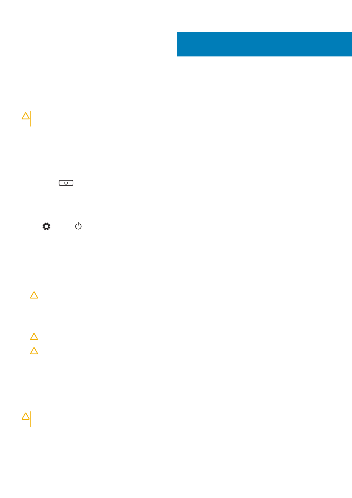
3. システムバッジフラップを裏返して [1]、ベースカバーをコンピュータに固定しているネジを外します [2]。
ベースネジにはトルクス #5 ドライバを、バッジフラップの内側にあるネジにはプラスドライバを使用します。
メモ:
」の手順に従います。
2
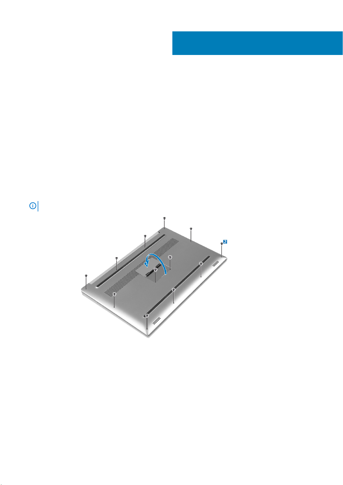
4. ベースカバーの端をてこの作用で持ち上げてコンピュータから取り外します。
コンポーネントの取り外しと取り付け 7
ベースカバーの取り付け
1. ベースカバーをコンピュータにセットして、所定の位置にカチッとはめ込みます。
2. ネジを締めてベースカバーをコンピュータに固定します。
ベースネジにはトルクス #5 ドライバを、システムバッジネジにはプラスドライバを使用するようにしてください。
メモ:
3. システムバッジフラップを裏返して、所定の位置にカチッとはめ込みます。
4. 「
コンピュータ内部の作業を終えた後に
」の手順に従います。
Removing the Battery
NOTE:
the A/C adapter from the system (while the system is turned on) to allow the system to drain the battery.
1. Follow the procedures in Before Working Inside Your Computer.
2. Remove the base cover.
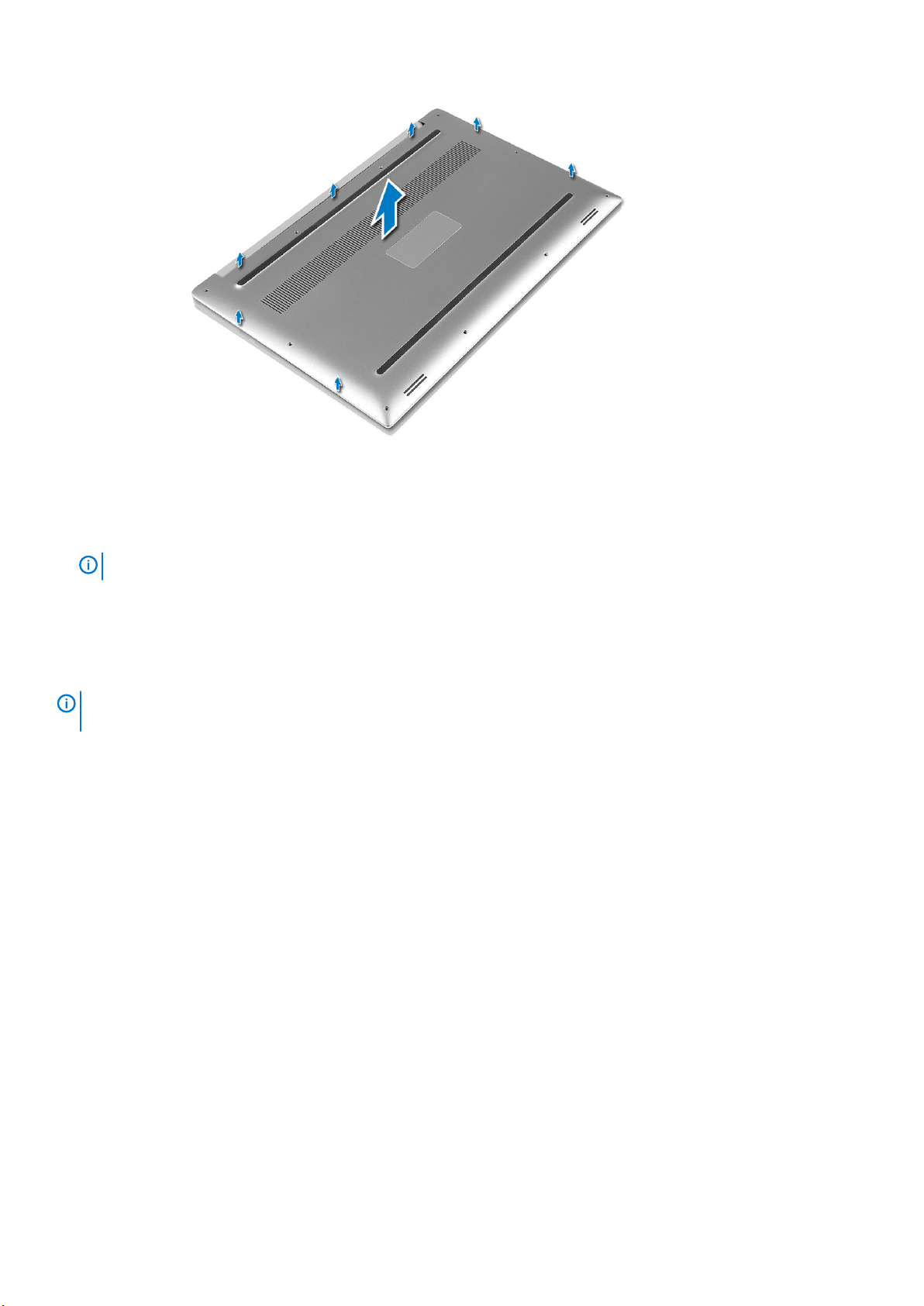
3. Perform the following steps to remove the battery:
a) Disconnect the battery cable from the system board [1].
b) Remove the screws that secure the battery to the computer [2].
c) Lift the battery off the computer [3].
• Do not apply pressure to the surface of the battery
• Do not bend
• Do not use tools of any kind to pry on or against the battery
• If a battery cannot be removed within the constraints above, please contact Dell technical support
Discharge the battery as much as possible before removing from the system. This can be done by disconnecting
8
コンポーネントの取り外しと取り付け
バッテリーの取り付け
1. バッテリーをバッテリーベイにセットして位置を合わせます。
2. バッテリーをコンピュータに固定するネジを締めます。
3. バッテリーケーブルをシステム基板に接続します。
4. ベースカバーを取り付けます。
5.
「コンピュータ内部の作業を終えた後に」
の手順に従います。
ハードドライブの取り外し
1. 「
コンピュータ内部の作業を始める前に
2. 次のコンポーネントを取り外します。
a) ベースカバー
b) バッテリー
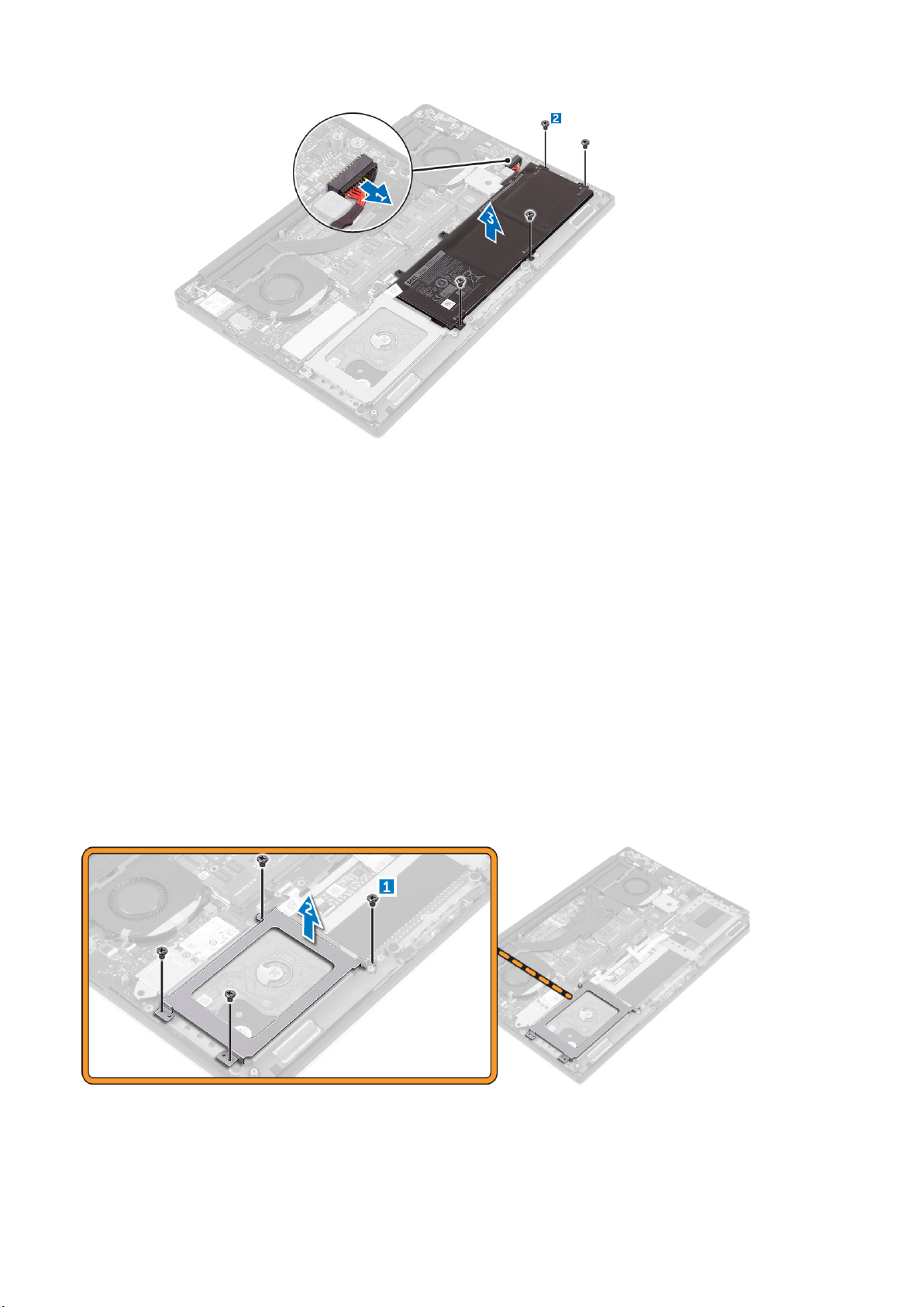
3. 次の手順を実行して、ハードドライブブラケットをコンピュータから取り外します。
a) ハードドライブブラケットをコンピュータに固定しているネジを外します [1]。
b) ハードドライブブラケットを持ち上げて、コンピュータから取り外します [2]。
」の手順に従います。
4. 次の手順を実行して、ハードドライブを取り外します。
a) ハードドライブケーブルをシステム基板から外します [1]。
b) ハードドライブを持ち上げて、コンピュータから取り外します [2]。
ーネントの取り外しと取り付け 9
コンポ
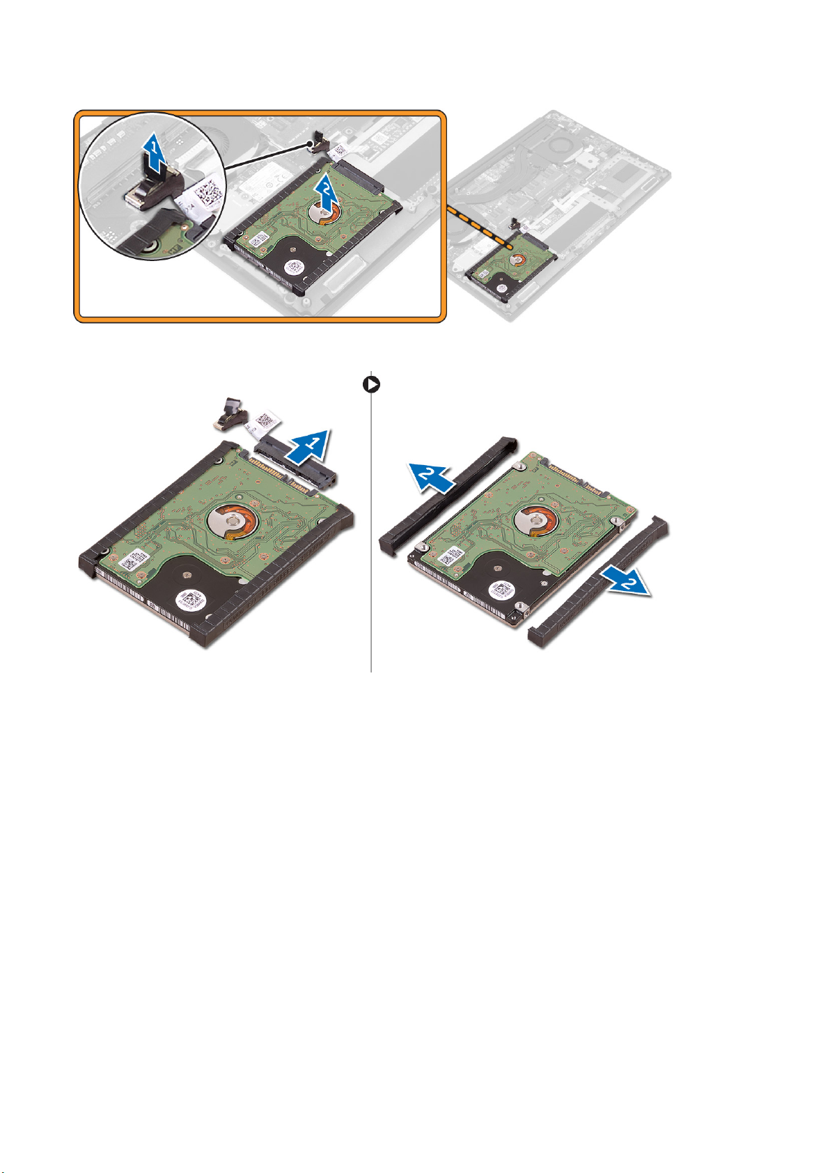
5. データケーブルコネクタを取り外し [1]、次に 2 つのエンドブラケットを引き出します [2]。
ハードドライブの取り付け
1. ハードドライブカバーをハードドライブに取り付けます。
2. ハードドライブインターポーザをハードドライブアセンブリに接続します。
3. ハードドライブアセンブリをパームレストアセンブリにセットします。
4. システム基板にハードドライブケーブルを接続します。
5. ハードドライブケージのネジ穴をハードドライブアセンブリのネジ穴の位置に合わせます。
6. ハードドライブケージをパームレストアセンブリに固定するネジを取り付けます。
7. 次のコンポーネントを取り付けます。
a) バッテリー
b) ベースカバー
8.
「コンピュータ内部の作業を終えた後に」
の手順に従います。
Removing the Solid-State Drive (half-length)
1. Follow the procedures in Before Working Inside Your Computer.
2. Remove the:
a) base cover
b) battery
10
コンポーネントの取り外しと取り付け
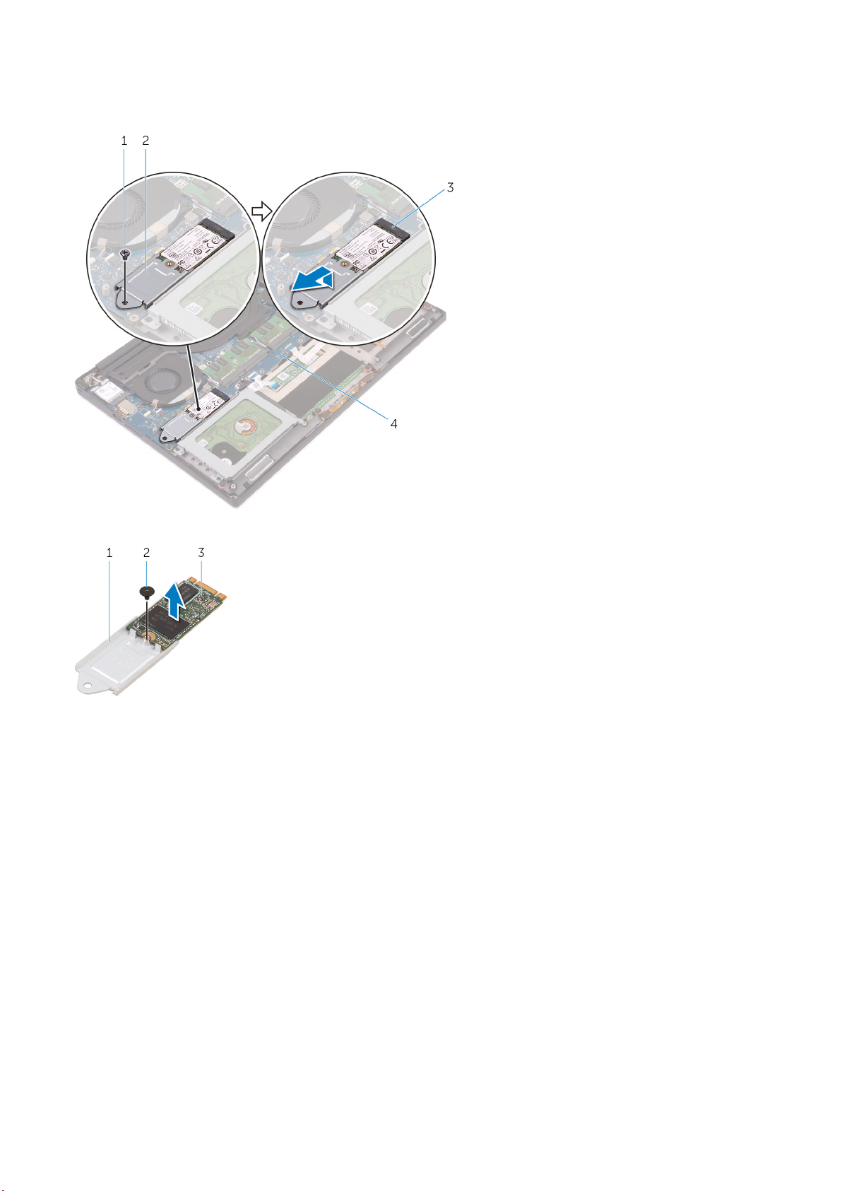
3. Remove the screw that secures the solid-state drive assembly to the system board [1, 2].
4. Lift and slide the solid-state drive assembly from the system board [3].
5. Remove the screw that secures the solid-state drive to the solid-state drive bracket [1, 2, 3].
6. Lift the solid-state drive off the solid-state drive bracket.
Installing the Solid-State Drive (half-length)
1. Align the screw hole on the solid-state drive bracket with the screw hole on the solid-state drive.
2. Replace the screw that secures the solid-state drive to the solid-state drive bracket.
3. Align the notches on the solid-state drive assembly with the tabs in the solid-state drive slot.
4. Slide the solid-state drive assembly at an angle into the solid-state drive slot.
5. Press the other end of the solid-state drive down and replace the screw that secures the solid-state drive to the system board.
6. Install the:
a) battery
b) base cover
7. Follow the procedures in After Working Inside Your Computer.
Removing the Solid-State Drive (full-length)
1. Follow the procedures in Before Working Inside Your Computer
2. Remove the:
a) base cover
b) battery
ーネントの取り外しと取り付け 11
コンポ
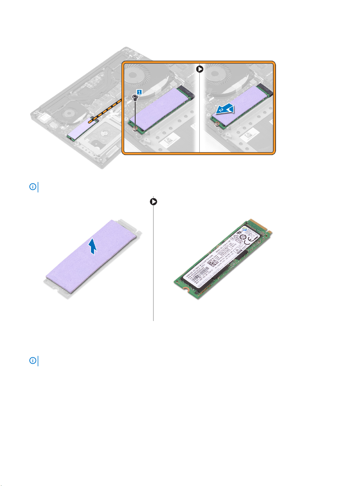
3. Remove the screw that secures the solid-state drive to the system board.
4. Remove the thermal pad from the SSD.
NOTE:
The thermal pad is applicable only for a PCIe SSD card.
Installing the Solid-State Drive (full-length)
1. Adhere the thermal pad to the solid-state drive.
NOTE:
2. Slide the solid-state drive at an angle into the solid-state drive slot.
3. Press the other end of the solid-state drive down and replace the screw that secures the solid-state drive to the system board.
4. Install the:
a) battery
b) base cover
5. Follow the procedures in After Working Inside Your Computer.
12
The thermal pad is applicable only for a PCIe SSD card.
コンポーネントの取り外しと取り付け
スピーカーの取り外し
1.
「コンピュータ内部の作業を始める前に」
2. 次のコンポーネントを取り外します。
a) ベースカバー
b) バッテリー
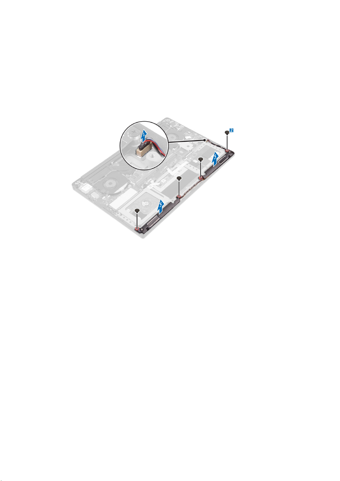
3. 次の手順を行って、スピーカーを取り外します。
a) スピーカーケーブルをシステム基板から外します [1]。
b) スピーカーをコンピュータに固定しているネジを外します [2]。
c) スピーカーをスピーカーケーブルとともに持ち上げ、コンピュータから取り外します [3]。
の手順に従います。
スピーカーの取り付け
1. 位置合わせポストを使用して、スピーカーをパームレストアセンブリにセットします。
2. スピーカーをパームレストアセンブリに固定するネジを取り付けます。
3. スピーカーケーブルをパームレストアセンブリの配線ガイドに沿って配線します。
4. システム基板にスピーカーケーブルを接続します。
5. 次のコンポーネントを取り付けます。
a) バッテリー
b) ベースカバー
6. 「
コンピュータ内部の作業を終えた後に
」の手順に従います。
WLAN カードの取り外し
1. 「
コンピュータ内部の作業を始める前に
2. 次のコンポーネントを取り外します。
a) ベースカバー
b) バッテリー
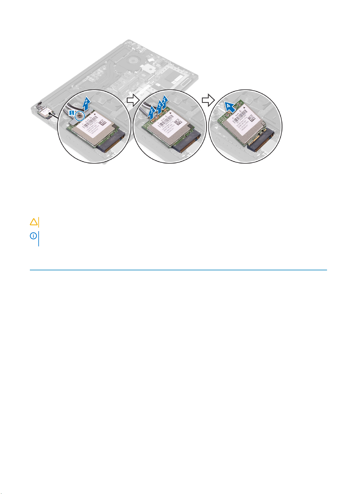
3. 以下の手順を行って、WLAN カードを取り外します。
a) ネジを外して WLAN カードをコンピュータに固定しているブラケットを外し [1]、ブラケットを持ち上げてコンピュータか
ら取り外します [2]。
b) アンテナケーブルを WLAN カードから外します [3]。
c) WLAN カードをスライドさせて、ボードのコネクタから取り外します [4]。
」の手順に従います。
ーネントの取り外しと取り付け 13
コンポ
WLAN カードの取り付け
1. WLAN カードの切り込みを I/O ボードの WLAN カードコネクタのタブに合わせます。
2. WLAN カードをパームレストアセンブリに固定するブラケットの位置を合わせます。
3. WLAN カードにアンテナケーブルを接続します。
WLAN カードへの損傷を避けるため、カードの下にケーブルを置かないでください。
注意:
メモ: アンテナケーブルの色はケーブルの先端の近くで確認できます。お使いのコンピュータがサポートする WLAN カード
用のアンテナケーブルの色分けは、次のとおりです。
表 1. WLAN カード用アンテナケーブルの色分け
WLAN カードのコネクタ アンテナケーブルの色
メイン(白色の三角形) 白色
補助(黒色の三角形) 黒色
多重入出力(グレーの三角形) グレー(オプション)
4. ネジを締め、ブラケットと WLAN カードをパームレストアセンブリに固定します。
5. 次のコンポーネントを取り付けます。
a) バッテリー
b) ベースカバー
6.
「コンピュータ内部の作業を終えた後に」
の手順に従います。
ファンの取り外し
1. 「
コンピュータ内部の作業を始める前に
2. 次のコンポーネントを取り外します。
a) ベースカバー
b) バッテリー
3. 次の手順を実行して、左側のビデオカードファンを取り外します。
a) LVDS ケーブルを拘束から外します [1][2]。
b) ファンケーブルをシステム基板から外します [3]。
c) ファンをコンピュータに固定しているネジを外します [4]。
d) ファンを持ち上げてコンピュータから取り外します [5]。
14
コンポーネントの取り外しと取り付け
」の手順に従います。

4. 次の手順を実行して、右側のシステムファンを取り外します。
a) LVDS ケーブルを拘束から外します [1]。
b) ファンケーブルをシステム基板から外します [2]。
c) ファンをコンピュータに固定しているネジを外します [3]。
d) ファンを持ち上げてコンピュータから取り外します [4]。
ファンの取り付け
1. 次の手順を実行し、システムファンを取り付けます。
a) 左側のファンのネジ穴をパームレストアセンブリのネジ穴に合わせます。
b) 左側のファンケーブルをシステム基板に接続します。
c) ディスプレイケーブルを左側のファンの配線ガイドに沿って配線します。
d) 左側のファンをシステム基板に固定するネジを取り付けます。
e) 右側のファンケーブルをシステム基板に接続します。
f) タッチスクリーンケーブルを右側のファンの配線ガイドに沿って配線します。
g) タッチスクリーンケーブルを右側のファンに固定するテープを貼り付けます。
h) ディスプレイケーブルをシステム基板に接続します。
i) 右側のファンをシステム基板に固定するネジを取り付けます。
2. 「
コンピュータ内部の作業を終えた後に
」の手順に従います。
ーネントの取り外しと取り付け 15
コンポ

ヒートシンクの取り外し
1. 「
コンピュータ内部の作業を始める前に
2. 次のコンポーネントを取り外します。
a) ベースカバー
b) バッテリー
3. ヒートシンクをシステム基板に固定しているネジを外します。
」の手順に従います。
4. ヒートシンクを持ち上げてコンピュータから取り外します。
ヒートシンクの取り付け
1. ヒートシンクのネジ穴をシステム基板のネジ穴の位置に合わせます。
2. ネジを取り付けてヒートシンクをシステム基板に固定します。
3. 次のコンポーネントを取り付けます。
a) バッテリー
b) ベースカバー
4.
「コンピュータ内部の作業を終えた後に」
の手順に従います。
16
コンポーネントの取り外しと取り付け

メモリモジュールの取り外し
1. 「
コンピュータ内部の作業を始める前に
2. 次のコンポーネントを取り外します。
a) ベースカバー
b) バッテリー
3. メモリモジュールが飛び出すまで、メモリモジュールから固定クリップを引き出します。メモリモジュールをシステム基板の
コネクタから取り外します。
」の手順に従います。
メモリモジュールの取り付け
1. メモリモジュールをメモリソケットに差し込みます。
2. 所定の位置にカチッと収まるまで、メモリモジュールを押し込みます。
メモ:
カチッという感触がない場合は、メモリモジュールを取り外して、もう一度取り付けてください。
3. 次のコンポーネントを取り付けます。
a) バッテリー
b) ベースカバー
4. 「
コンピュータ内部の作業を終えた後に
」の手順に従います。
システム基板の取り外し
1. 「
コンピュータ内部の作業を始める前に
2. 次のコンポーネントを取り外します。
a) ベースカバー
b) バッテリー
c) ファン
d) ヒートシンク
e) SSD
f) メモリモジュール
メモ
: お使いのコンピュータのサービスタグはシステムバッジフラップの下にあります。 システム基板の取り付け後に、
BIOS にサービスタグを入力する必要があります。
メモ: システム基板からケーブルを外す前に、各コネクタの位置をメモしておき、システム基板の取り付け後に正しく元
の場所に戻すことができるようにしてください。
」の手順に従います。
コンポーネントの取り外しと取り付け 17
3. LVDS の金属ブラケットをシステム基板に固定しているネジを外して [1]、ブラケットをコンピュータから取り外します [2]。次
に、LVDS ケーブルをシステム基板から外します [3]。
4. コネクタラッチを引き出して、すべてのケーブルをシステム基板から外します。
5. 次の手順を実行して、システム基板をコンピュータから取り外します。
a) システム基板をコンピュータに固定しているネジを外します [1]。
b) システム基板を持ち上げてコンピュータから取り外します [2]。
18
コンポーネントの取り外しと取り付け

システム基板の取り付け
1. コンピュータ上でシステム基板の位置を合わせます。
2. システム基板をパームレストアセンブリに固定するネジを取り付けます。
3. 電源アダプタポートケーブル、スピーカーケーブル、キーボードコントロールボードケーブル、タッチパッドケーブル、タッチス
クリーンケーブルをシステム基板に接続します。
4. ディスプレイケーブルをシステム基板に接続します。
5. ディスプレイケーブルブラケットのネジ穴をシステム基板のネジ穴に合わせます。
6.
「コンピュータ内部の作業を終えた後に」
の手順に従います。
Removing the Audio Daughter Board
1. Follow the procedures in Before Working Inside Your Computer.
2. Remove the:
a) base cover
b) battery
c) WLAN card
d) hard drive
e) SSD (half length)
f) SSD (full length)
g) fans
h) heatsink
i) memory modules
j) system board
3. Remove the two screws that secure the audio daughter board to the system board.
ーネントの取り外しと取り付け 19
コンポ

a. system board
b. screws
4. Flip the system board over, then lift the audio daughter board from the system board.
a. audio daughter board
Installing the audio daughter board
1. Align the screw holes on the audio daughter board with the screw holes on the system board.
2. Flip the system board over, then replace the screws that secure the audio daughter board to the system board.
3. Install the:
a) system board
b) memory modules
c) heat-sink assembly
d) fans
e) solid-state drive (half-length)
f) solid-state drive (full-length)
g) hard drive
h) wireless card
i) battery
20
コンポーネントの取り外しと取り付け

j) base cover
4. Follow the procedures in After Working Inside Your Computer.
キーボードの取り外し
1. 「
コンピュータ内部の作業を始める前に
2. 次のコンポーネントを取り外します。
a) ベースカバー
b) バッテリー
c) ファン
d) ヒートシンク
e) SSD
f) メモリモジュール
g) システム基板
3. 次の手順を実行して、キーボードとバックライトコネクタをコンピュータから取り外します。
a) コネクタのロックを持ち上げて [1]、ケーブルをコネクタから外します [2]。
b) ネジシールドをはがします [3]。
」の手順に従います。
4. LVDS ケーブルの配線を外して [1]、キーボードをコンピュータに固定しているネジを外します [2]。
5. キーボードを持ち上げて、コンピュータから取り外します。
ーネントの取り外しと取り付け 21
コンポ

キーボードの取り付け
1. 透明シートをキーボードに貼り付けます。
2. キーボードのネジ穴をパームレストアセンブリのネジ穴の位置に合わせます。
3. キーボードをパームレストアセンブリに固定するネジを取り付けます。
4. キーボードをパームレストアセンブリに固定しているネジに透明シートを貼り付けます。
5. キーボードケーブルとキーボードバックライトケーブルをキーボードコントロールボードに接続します。
6. 次のコンポーネントを取り付けます。
a) システム基板
b) ハードドライブ
c) ベースカバー
7.
「コンピュータ内部の作業を終えた後に」
の手順に従います。
ディスプレイアセンブリの取り外し
1. 「
コンピュータ内部の作業を始める前に
2. 次のコンポーネントを取り外します。
a) ベースカバー
b) バッテリー
3. 次の手順を実行します。
a) 左側の LVDS ケーブルを外します [1]。
b) 金属ブラケットを固定しているネジを外し [2]、ブラケットを持ち上げてコンピュータから取り外します [3]。
c) 右側の LVDS ケーブルをシステム基板から外します [4]。
」の手順に従います。
22
コンポーネントの取り外しと取り付け

4. 図に示すようにコンピュータをテーブルの端にセットして、ディスプレイアセンブリをコンピュータに固定しているネジを外
します [1]。次に、ディスプレイアセンブリを持ち上げてコンピュータから取り外します [2]。
ディスプレイアセンブリの取り付け
1. スピーカーが端を向かないようにパームレストアセンブリをテーブルの端に置きます。
2. パームレストアセンブリのネジ穴をディスプレイヒンジのネジ穴の位置に合わせます。
コンポ
ーネントの取り外しと取り付け 23

3. ディスプレイヒンジをパームレストアセンブリに固定するネジを取り付けます。
4. テープを貼り付けて、タッチスクリーンケーブルをファンの配線ガイドに沿って配線します。
5. タッチスクリーンケーブルとディスプレイケーブルをシステム基板に接続します。
6. ディスプレイケーブルブラケットをシステム基板に固定するネジを取り付けます。
7.
「コンピュータ内部の作業を終えた後に」
の手順に従います。
DC 入力コネクタの取り外し
1. 「
コンピュータ内部の作業を始める前に
2. 次のコンポーネントを取り外します。
a) ベースカバー
b) バッテリー
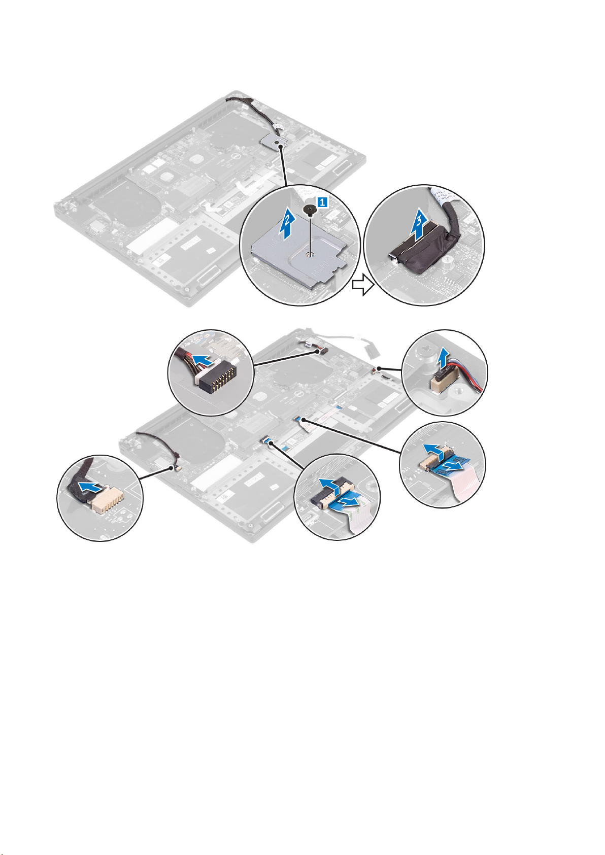
3. 以下の手順を行って、I/O ボードを取り外します。
a) DC 入力ケーブルをシステム基板から外します [1]。
b) DC 入力ケーブルをコンピュータに固定しているネジを外します。
c) DC 入力コネクタをコンピュータから取り外します。
」の手順に従います。
DC 入力アダプタポートの取り付け
1. DC 入力アダプタポートをパームレストアセンブリのスロットにセットします。
2. 電源アダプタポートケーブルをパームレストアセンブリの配線ガイドに沿って配線します。
3. 電源アダプタポートをパームレストアセンブリに固定するネジを取り付けます。
4. 電源アダプタポートケーブルをシステム基板に接続します。
5. 次のコンポーネントを取り付けます。
a) バッテリー
b) ベースカバー
6. 「
コンピュータ内部の作業を終えた後に
」の手順に従います。
Removing the antenna cover
1. Follow the procedures in Before Working Inside Your Computer.
2. Remove the:
a) base cover
b) battery
c) WLAN Card
24
コンポーネントの取り外しと取り付け

d) display assembly
3. Carefully turn the display hinges at an angle.
Figure 1. Turning the display hinge
a. display assembly
b. display hinges (2)
4. Slide and lift the antenna cover away from the display assembly.
Figure 2. Removing the antenna cover
a. display assembly
b. antenna cover
Installing the antenna cover
1. Replace the antenna cover on the display assembly.
2. Turn the display hinges to the normal position.
3. Install the:
a) display assembly
b) wireless card
c) battery
d) base cover
4. Follow the procedures in After Working Inside Your Computer.
ーネントの取り外しと取り付け 25
コンポ

Removing the display hinges
1. Follow the procedures in Before Working Inside Your Computer.
2. Remove the:
a) base cover
b) battery
c) WLAN Card
d) display assembly
e) antenna cover
3. Peel off the tape to access the screws on the display hinges.
a. tape
b. display hinges (2)
4. Remove the screws that secure the display hinges to the display assembly.
5. Carefully lift the display hinges off the display assembly.
a. screws (6)
b. display hinges (2)
Installing the display hinges
1. Align the screw holes on the display hinges with the screw holes on the display assembly.
26
コンポーネントの取り外しと取り付け

2. Replace the screws that secure the display hinges to the display assembly.
3. Adhere the tape to the display hinges.
4. Install the:
a) antenna cover
b) display assembly
c) wireless card
d) battery
e) base cover
5. Follow the procedures in After Working Inside Your Computer.
Removing the antenna module
1. Follow the procedures in Before Working Inside Your Computer.
2. Remove the:
a) base cover
b) battery
c) wireless card
d) display assembly
e) antenna cover
f) display hinges
3. Peel the tape that covers the antenna cables.
4. Remove the screws that secure the antenna module to the display assembly.
5. Lift the antenna module away from the display assembly.
tape 2. antenna cable
1.
3. screws (4) 4. antenna module
5. display assembly
Installing the antenna module
1. Align the screw holes on the antenna module with the screw holes on the display assembly.
2. Replace the screws that secure the antenna module to the display assembly.
3. Adhere the tape that covers the antenna cable.
4. Install the:
a) display hinges
コンポ
ーネントの取り外しと取り付け 27

b) antenna cover
c) display assembly
d) wireless card
e) battery
f) base cover
5. Follow the procedures in After Working Inside Your Computer.
Removing the palm-rest assembly
1. Follow the procedures in Before Working Inside Your Computer.
2. Remove the:
a) base cover
b) battery
c) memory modules
d) Follow the procedure from step 1 to step 4 in “Removing the hard drive
e) wireless card
f) speakers
g) heat-sink
h) fans
i) display assembly
j) power-adapter port
k) system board
l) keyboard
After performing the steps in the prerequisites we are left with the palm-rest assembly.
a. palm-rest assembly
Installing the palm-rest assembly
1. Place the palm-rest assembly on a clean and flat surface.
2. Install the:
a) keyboard
b) system board
c) power-adapter port
d) display assembly
e) fans
f) heat-sink assembly
g) speakers
h) wireless card
i) Follow the procedure from step 3 to step 6 in “Replacing the hard drive”.
28
コンポーネントの取り外しと取り付け

j) memory modules
k) battery
l) base cover
3. Follow the procedures in After Working Inside Your Computer.
コンポーネントの取り外しと取り付け 29

3
セットアップユーティリティ
セットアップユーティリティでは、タブレットデスクトップノートパソコンハードウェアの管理と BIOS レベルオプションの指定
を行うことができます。セットアップユーティリティから実行できる操作は次のとおりです。
• ハードウェアの追加または削除後に NVRAM 設定を変更する。
• システムハードウェアの構成を表示する。
• 内蔵デバイスの有効 / 無効を切り替える。
• パフォーマンスと電力管理のしきい値を設定する。
• コンピュータのセキュリティを管理する。
トピック:
• 起動順序
• ナビゲーションキー
• セットアップユーティリティのオプション
• Windows での BIOS のアップデート
• システムパスワードおよびセットアップパスワード
起動順序
起動順序を利用すると、セットアップユーティリティで定義されたデバイス起動順序をバイパスし、特定のデバイス(例:オプテ
ィカルドライブまたはハードドライブ)から直接起動することができます。パワーオンセルフテスト(POST)中にデルのロゴが
表示されたら、次の操作ができます。
• <F2> を押してセットアップユーティリティにアクセスする
• <F12> を押して 1 回限りの起動メニューを立ち上げる
1 回限りの起動メニューでは診断オプションを含むオプションから起動可能なデバイスを表示します。起動メニューのオプション
は以下のとおりです。
• リムーバブルドライブ(利用可能な場合)
• STXXXX ドライブ
XXX は、SATA ドライブの番号を意味します。
メモ:
• オプティカルドライブ(利用可能な場合)
• 診断
Diagnostics(診断)を選択すると ePSA 診断 画面が表示されます。
メモ:
起動順序画面ではシステムセットアップ画面にアクセスするオプションを表示することも可能です。
ナビゲーションキー
: ほとんどのセットアップユーティリティオプションで、変更内容は記録されますが、システムを再起動するまでは有効
メモ
になりません。
キー ナビゲーション
上矢印 前のフィールドに移動します。
下矢印 次のフィールドへ移動します。
<Enter> 選択したフィールドの値を選択するか(該当する場合)、フィールド内のリンクに移動します。
スペースバー ドロップダウンリストがある場合は、展開したり折りたたんだりします。
Tab 次のフォーカス対象領域に移動します。
メモ: 標準グラフィックブラウザ用に限られます。
30 セットアップユーティリティ

キー ナビゲーション
<Esc> メイン画面が表示されるまで、前のページに移動します。メイン画面で <Esc> を押すと、未保存の変更内
容を保存するよう求めるメッセージが表示され、システムが再起動されます。
セットアップユーティリティのオプション
メモ: お使いのコンピュータおよび取り付けられているデバイスによっては、このセクションに記載されている項目の一部が
表示されない場合があります。
表 2. メイン
オプション 説明
System Time/Date 日付と時刻を設定できます。
BIOS Version BIOS のバージョンが表示されます。
Product Name 製品名を表示します。
Dell Precision M3800(デフォルト設定)
Service Tag サービスタグを表示します。
Asset Tag アセットタグを表示します。
None(なし)(デフォルト設定)
CPU Type CPU のタイプを表示します。
CPU Speed CPU のスピードを表示します。
CPU ID CPU ID を表示します。
CPU Cache CPU キャッシュのサイズを表示します。
Fixed HDD HDD のタイプとサイズを表示します。
WDC WD10SPCX-75HWSTO(1000 GB)(デフォルト設定)
mSATA Device mSATA デバイスのタイプとサイズを表示します。
AC Adapter Type AC アダプタのタイプを表示します。
None(なし)(デフォルト設定)
System Memory システムメモリのサイズを表示します。
Extended Memory 拡張メモリのサイズを表示します。
Memory Speed メモリのスピードを表示します。
Keyboard Type キーボードのタイプが表示されます。
Backlite(バックライト)(デフォルト設定)
表 3. 拡張機能
オプション 説明
Intel (R) SpeedStep (TM) Intel (R) SpeedStep (TM) の機能を有効または無効にすることができます。
Enabled(有効)(デフォルト設定)
Virtualization このオプションでは、Intel 仮想化テクノロジにより提供される追加のハードウェア機能を仮想
マシンモニタ(VMM)で使用できるかどうかを指定します。仮想化機能を有効または無効に
することができます。
Enabled(有効)(デフォルト設定)
USB Emulation USB エミュレーション機能を有効または無効にすることができます。
Enabled(有効)(デフォルト設定)
セットアップユーティリティ 31

オプション 説明
USB PowerShare USB PowerShare 機能を有効または無効にすることができます。
Enabled(有効)(デフォルト設定)
USB Wake Support このオプションでは、USB デバイスでシステムを待機状態からウェイクさせることができま
す。
Disable(無効)(デフォルト設定)
SATA Operation SATA オペレーションの情報を表示します。
Adapter Warnings アダプタ警告機能を有効または無効にすることができます。
Multimedia Key Behaviour
Battery Health バッテリーの状態 を表示します。
Battery Charge Configuration
Miscellaneous Devices 各種オンボードデバイスを有効または無効にすることができます。オプションは次の通りで
表 4. セキュリティ
オプション 説明
Unlock Setup Status
Function Key(ファンクションキー)(デフォルト設定)
Adaptive(適応) (デフォルト設定)
す。
• 外付け USB ポート - Enabled(有効)(デフォルト設定)
• USB デバッグ - Disabled(無効) (デフォルト設定)
Unlocked(アンロック) (デフォルト設定)
Admin Password Status 管理者パスワードのステータスを表示します。
デフォルト設定:Not set(設定なし)
System Password Status システムパスワードのステータスを表示します。
デフォルト設定:Not set(設定なし)
HDD Password Status システムパスワードのステータスを表示します。
デフォルト設定:Not set(設定なし)
Asset Tag アセットタグを設定できます。
Admin Password 管理者(Admin)パスワードを設定、変更、または削除することができます。
メモ: システムパスワードまたはハードドライブパスワードを設定する前に、管理者
パスワードを設定してください。
メモ: パスワードが正常に変更されると、すぐに反映されます。
メモ: 管理者パスワードを削除すると、システムパスワードとハードドライブパスワ
ードも自動的に削除されます。
メモ: パスワードが正常に変更されると、すぐに反映されます。
System Password システムパスワードを設定、変更、または削除することができます。
メモ: パスワードが正常に変更されると、すぐに反映されます。
HDD Password 管理者パスワードの設定、変更、または削除を行うことができます。
Password Change 管理者パスワードが設定されている場合に、システムパスワードとハードドライブパスワ
ードを設定する許可を有効または無効にすることができます。
デフォルト設定:Permitted(許可)
Computrace オプションである Computrace ソフトウェアをアクティブまたは無効にすることができ
ます。オプションは次の通りです。
• Deactivate(非アクティブ)(デフォルト設定)
32 セットアップユーティリティ

オプション 説明
• Activate(アクティブ)
メモ: Activate(アクティブ)および Disable(無効)オプションでは機能を永久的
に起動または無効にするため、その後の変更はできません。
TPM Security このオプションでは、システムの TPM(Trusted Platform Module)を有効にし、オペレ
ーティングシステムで認識されるか否かをコントロールします。無効にすると、BIOS は
POST 中に TPM をオンにしません。TPM は機能せず、オペレーティングシステムによっ
て認識されなくなります。有効にした場合、BIOS は POST 中に TPM をオンにし、オペ
レーティングシステムで使用できるようになります。このオプションはデフォルトで
効に設定されています。
メモ: このオプションを無効にすると、TPM を設定を変更したり、TPM に保存して
いる情報やキーを削除、または変更することができなくなります。TPM がオフにな
るので、使用できなくなります。このオプションを有効にすると、TPM を無効にす
る前と同様、機能するようになります。
メモ: このオプションへの変更はすぐに反映されます。
表 5. 起動
オプション 説明
Boot List Option
Secure Boot このオプションは、安全起動機能を有効または無効にします。
デフォルト設定: Legacy(レガシー)
• Disabled(無効)(デフォルト設定)- Windows 7
• Enabled(有効)- Windows 8.1
有
Load Legacy Option ROM このオプションでは、レガシーオプション ROM のロード機能を有効または無効にしま
す。
• Enabled(有効)(デフォルト設定)- Windows 7
• Disabled(無効)- Windows 8.1
Set Boot Priority コンピュータの OS 検出の順序を変更することができます。
• 1 番目の 起動優先[CD/DVD/CD-RW ドライブ]
• 2 番目の起動優先[ネットワーク]
• 3 番目の起動優先[ミニ SSD]
• 4 番目の起動優先[USB ストレージデバイス]
• 5 番目の起動優先[ハードドライブ ]
• 6 番目の起動優先[ディスケットドライブ ]
表 6. 終了
オプション 説明
Save Changes and Reset 変更を保存できます。
Discard Changes and Reset 変更を破棄できます。
Restore Defaults デフォルトオプションに戻すことができます。
Discard Changes 変更を破棄できます。
Save Changes 変更を保存できます。
Windows での BIOS のアップデート
システム基板を交換する場合やアップデートが入手できる場合は、お使いの BIOS(セットアップユーティリティ)のアップデート
を推奨しています。ラップトップの場合、お使いのコンピュータのバッテリーがフル充電されていてコンセントに接続されている
ことを確認してください。
セットアップユ
ーティリティ 33

メモ: BitLocker が有効になっている場合は、システム BIOS のアップデート前に BitLocker を一時停止して、BIOS アップデ
ートの完了後に再び有効にする必要があります。
1. コンピュータを再起動します。
2. Dell.com/support にアクセスしてください。
• サービスタグやエクスプレスサービスコードを入力し、Submit(送信)をクリックします。
• Detect Product(製品を検出)をクリックして、画面の指示に従います。
3. サービスタグの検索または検出ができない場合は、Choose from all products(すべての製品から選択)をクリックします。
4. リストから Products(製品) カテゴリを選択します。
メモ: 製品ページに到達するための該当カテゴリを選択します。
5. お使いのコンピュータモデルを選択すると、そのコンピュータの製品サポートページが表示されます。
6. Get drivers(ドライバを取得)をクリックし、Drivers and Downloads(ドライバとダウンロード)をクリックします。
Drivers and Downloads(ドライバとダウンロード)セクションが開きます。
7. Find it myself(自分で検索)をクリックします。
8. BIOS をクリックして、BIOS のバージョンを表示します。
9. 最新の BIOS ファイルを選択し、Download(ダウンロード)をクリックします。
10. ダウンロード方法を以下から選択してください ウィンドウで希望のダウンロード方法を選択し、Download File(ファイルの
ダウンロード)をクリックします。
ファイルのダウンロードウィンドウが表示されます。
11. ファイルをコンピュータに保存する場合は、Save(保存)をクリックします。
12. Run(実行)をクリックしてお使いのコンピュータに更新された BIOS 設定をインストールします。
画面の指示に従います。
メモ
: BIOS のバージョンを 3 つを超えるリビジョンにアップデートしないことをお勧めします。例:BIOS を 1.0 から 7.0 に
アップデートする場合は、まずバージョン 4.0 をインストールしてからバージョン 7.0 をインストールします。
システムパスワードおよびセットアップパスワード
システムパスワードとセットアップパスワードを作成してお使いのコンピュータを保護することができます。
パスワードの種
類
システムパスワードシステムにログオンする際に入力が必要なパスワードです。
セットアップパス
ワード
注意: パスワード機能は、コンピュータ内のデータに対して基本的なセキュリティを提供します。
注意: コンピュータをロックせずに放置すると、コンピュータ上のデータにアクセスされる可能性があります。
メモ: お使いのコンピュータは、出荷時にシステムパスワードとセットアップパスワードの機能が無効に設定されています。
システムパスワードおよびセットアップパスワードの割り当
説明
お使いのコンピュータの BIOS 設定にアクセスして変更をする際に入力が必要なパスワードです。
て
ステータスが未設定の場合のみ、新しいシステムパスワードを割り当てることができます。
セットアップユーティリティを起動するには、電源投入または再起動の直後に <F2> を押します。
1. システム BIOS 画面またはセットアップユーティリティ画面で、セキュリティを選択し、<Enter> を押します。
セキュリティ画面が表示されます。
2. システムパスワードを選択し、新しいパスワードを入力フィールドでパスワードを作成します。
以下のガイドラインに従ってシステムパスワードを設定します。
34
セットアップユーティリティ

• パスワードの文字数は 32 文字までです。
• 0 から 9 までの数字を含めることができます。
• 小文字のみ有効です。大文字は使用できません。
• 特殊文字は、次の文字のみが利用可能です:スペース、(”)、(+)、(,)、(-)、(.)、(/)、(;)、([)、
(\)、(])、(`)。
3. 新しいパスワードの確認フィールドで以前入力したシステムパスワードを入力し、OK をクリックします。
4. <Esc> を押すと、変更の保存を求めるメッセージが表示されます。
5. <Y> を押して変更を保存します。
コンピュータが再起動します。
既存のシステムパスワードおよび / またはセットアップパス ワードの削除または変更
既存のシステムパスワードおよび/またはセットアップパスワードを削除または変更する前に Password Status(パスワードステー
タス)がロック解除(システムセットアップで)になっていることを確認します。
ロック されている場合、既存のシステムパスワードまたはセットアップパスワードを削除または変更することはできません。
セットアップユーティリティを起動するには、電源投入または再起動の直後に <F2> を押します。
1. システム BIOS 画面またはセットアップユーティリティ画面で、システムセキュリティを選択し、<Enter> を押します。
システムセキュリティ画面が表示されます。
2. システムセキュリティ画面でパスワードステータスがロック解除に設定されていることを確認します。
3. System Password(システムパスワード)を選択し、既存のシステムパスワードを変更または削除して、<Enter> または
<Tab> を押します。
4. Setup Password(セットアップパスワード)を選択し、既存のセットアップパスワードを変更または削除して、<Enter> また
は <Tab> を押します。
メモ
: システムパスワードおよび/またはセットアップパスワードを変更する場合、プロンプトが表示されたら新しいパス
ワードを再度入力してください。システムパスワードおよび/またはセットアップパスワードを削除する場合、プロンプト
が表示されたら削除を確認してください。
5. <Esc> を押すと、変更の保存を求めるメッセージが表示されます。
6. <Y> を押して変更を保存しセットアップユーティリティを終了します。
コンピュータが再起動します。
Password Status(パスワードステータス)が
セットアップユ
ーティリティ 35

4
診断
コンピューターに問題が起こった場合、デルのテクニカルサポートに電話する前に ePSA 診断を実行してください。診断プログラ
ムを実行する目的は、特別な装置を使用せず、データが失われる心配をすることなくコンピューターのハードウェアをテストする
ことです。お客様がご自分で問題を解決できない場合でも、サービスおよびサポート担当者が診断プログラムの結果を使って問題
解決の手助けを行うことができます。
トピック:
• ePSA(強化された起動前システムアセスメント)診断
• デバイスステータスライト
ePSA(強化された起動前システムアセスメント)診 断
ePSA 診断(システム診断としても知られている)ではハードウェアの完全なチェックを実施します。ePSA には BIOS が組み込ま
れており、BIOS によって内部的に起動されます。組み込み型システム診断プログラムには、特定のデバイスやデバイスグループ
用の一連のオプションが用意されており、以下の処理が可能です。
• テストを自動的に、または対話モードで実行
• テストの繰り返し
• テスト結果の表示または保存
• 詳細なテストで追加のテストオプションを実行し、障害の発生したデバイスに関する詳しい情報を得る
• テストが問題なく終了したかどうかを知らせるステータスメッセージを表示
• テスト中に発生した問題を通知するエラーメッセージを表示
注意
: システム診断プログラムは、お使いのコンピュータをテストする場合にのみ使用してください。このプログラムを他の
コンピュータで使用すると、無効な結果やエラーメッセージが発生する場合があります。
メモ: 特定のデバイスのテストではユーザー操作が必要となる場合があります。診断テストを実行する際には、常にコンピュ
ータ端末の前にいるようにしてください。
デバイスステータスライト
7.
表
アイコン 説明
コンピュータの電源を入れると点灯します。
36 診断

技術仕様
メモ: 提供される内容は地域により異なる場合があります。コンピュータの構成の詳細を確認するには、スタート (スタ
ートアイコン) > ヘルプとサポートの順にクリックし、お使いのコンピュータに関する情報を表示するオプションを選択して
ください。
表 8. システム情報
機能 仕様
システムチップセット Mobile Intel HM170 Express チップセット / Intel CM236
DMA チャネル VT-d DMA リマップエンジン(2)
割り込みレベル インテル 64 および IA-32 アーキテクチャ
BIOS チップ(NVRAM) 8 MB
表 9. プロセッサ
機能 仕様
プロセッサのタイプ 第 6 世代 Intel Core i3/ 第 6 世代 Intel Quad Core i5/ 第 6 世代 Intel Quad Core
i7
L1 キャッシュ プロセッサのタイプに応じて最大 256 KB キャッシュ
L2 キャッシュ プロセッサのタイプに応じて最大 1024 KB キャッシュ
L3 キャッシュ プロセッサのタイプに応じて最大 6144 KB キャッシュ
5
表 10. メモリ
機能 仕様
タイプ DDR4
速度 2133 MHz
コネクタ SoDIMM ソケット(2)
容量 8 GB、16 GB、および 32 GB
最小メモリ 8 GB
最大メモリ 32 GB
表 11. ビデオ
機能 仕様
タイプ
ディスクリート NVIDIA GeForce GTX 960M
内蔵 Intel HD グラフィックス 530
データバス PCIE x16、Gen3
メモリ
ディスクリート 最大 2 GB GDDR5
内蔵 共有システムメモリ
技術仕様 37

表 12. オーディオ
機能 仕様
内蔵 デュアルチャネルハイデフィニションオーディオ
表 13. 通信
機能 仕様
ネットワークアダプタ 付属の USB-to-Ethernet ドングルを使ったイーサネット
メモ: 付属の RJ-45(10/100/1000 Base-T、IPv 6)はありません。
ワイヤレス
表 14. ポートとコネクタ
機能 仕様
オーディオ
USB 3.0
ビデオ
メモリカードリーダー SD 4.0
表 15. ディスプレイ
機能 仕様
タイプ 1920 x 1080 FHD
サイズ 15.6 インチ FHD
• Wi-Fi 802.11ac
• Wi-Fi 802.11a/g/n
• Bluetooth 4.1
• Intel WiDi(オプション)
• ヘッドセットポート(ヘッドフォンとマイクのコンボ)(1)
• PowerShare 機能付き USB 3.0 ポート(2)
• PowerShare 機能付き Thunderbolt 3 ポート(USB-C)(1)
• HDMI 1.4(1)
3840 x 2160 UltraHD
15.6 インチ UltraHD
寸法:
高さ 194.50 mm(7.66 インチ)
幅 345.60 mm(13.61 インチ)
対角線 396.52 mm(15.61 インチ)
有効領域(X/Y) 194.50 mm(7.66 インチ)x 345.60 mm(13.61 インチ)x 396.52 mm(15.61 イ
ンチ)
最大解像度 1920 X 1080 ピクセル / 3840 X 2160 ピクセル
最大輝度 400 ニット
動作角度 0°(閉じた状態) ~ 135°
リフレッシュレート 60 Hz
最小視野角:
水平方向 80/80
垂直方向 80/80
38 技術仕様

表 16. キーボード
機能 仕様
キー数
レイアウト QWERTY/AZERTY/ 漢字
表 17. タッチパッド
機能 仕様
動作領域:
X 軸 105 mm
Y 軸 80 mm
表 18. カメラ
機能 仕様
タイプ HD カメラ / デジタルアレイマイク
静止画像の解像度 0.92 メガピクセル(最大)
動画の解像度 30 フレーム / 秒で 1280 x 720 ピクセル(HD)(最大)
対角線 74 度
• アメリカ:80 キー
• イギリス:81 キー
• ブラジル:81 キー
• 日本:84 キー
表 19. ストレージ
機能 仕様
ストレージ:
ストレージインタフェース SATA 3 Gbps
SATA 6 Gbps
ドライブ構成:
ハードドライブ(オプション) 内蔵 2.5 インチ SATA HDD(Intel Smart Response Technology をサポート)
ソリッドステートドライブ(オプション)Intel Cache 対応ソリッドステートドライブ(SSD)(1)
サイズ: 512 GB および 1 TB
表 20. バッテリー
機能 仕様
タイプ リチウムポリマー 3 セル(56 Whr)/ 6 セル(84 Whr)
寸法:
56 Whr:
奥行き 223.20 mm(8.79 インチ)
高さ 7.20 mm(0.28 インチ)
幅 71.80 mm(2.83 インチ)
重量 0.24 kg(0.54 ポンド)
84 Whr:
奥行き 330.50 mm(13.01 インチ)
高さ 7.20 mm(0.28 インチ)
幅 71.80 mm(2.83 インチ)
技術仕様 39

機能 仕様
重量 0.34 kg(0.76 ポンド)
電圧 11.4 V
寿命 300 サイクル(充電 / 放電)
温度範囲:
動作時(概算)
非動作時 –40 ~ 65 °C(–40 ~ 149 °F)
コイン型電池 ML1220
表 21. AC アダプタ
機能 仕様
入力電圧 100 ~ 240 VAC
入力電流(最大) 1.80 A
入力周波数 50 ~ 60 Hz
出力電力 130 W
出力電流 6.67 A
定格出力電圧 19.50 VDC
寸法:
高さ 22 mm(0.86 インチ)
幅 66 mm(2.59 インチ)
奥行き 143 mm(5.62 インチ)
温度範囲:
動作時 0 °C ~ 40 °C(32 °F ~ 104 °F)
非動作時 –40 °C ~ 70 °C(–40 °F ~ 158 °F)
• 充電:0 °C ~ 50 °C(32 °F ~ 158 °F)
• 放電: 0 °C ~ 70 °C(32 °F ~ 122 °F)
• 動作時:0 °C ~ 35°C(32°F ~ 95°F)
表 22. 外形寸法
寸法 仕様
高さ: 17 mm(0.66 インチ)
幅 357 mm(14.06 インチ)
奥行き 235 mm(9.27 インチ)
重量(最小) 2 kg(4.41 ポンド)
表 23. 環境
機能 仕様
温度範囲:
動作時 0 °C ~ 40 °C(32 °F ~ 104°F)
保管時 –40 °C ~ 70 °C(–40 °F ~ 158 °F)
相対湿度(最大):
動作時 10 ~ 90 %(結露しないこと)
保管時 10 ~ 95 %(結露しないこと)
最大振動:
40 技術仕様

機能 仕様
動作時 0.66 GRMS、2 ~ 600 Hz
保管時 1.3 GRMS、2 ~ 600 Hz
最大衝撃:
動作時 110 G(2 ms)
非動作時 160 G(2 ms)
高度:
動作時
保管時 –15.2 m ~ 10,668 m(–50 ~ 35,000 フィート)
空気中浮遊汚染物質レベル G1(ISA-S71.04-1985 の定義による)
–15.2 m ~ 30482000 m(–50 ~10,0006560 フィート)
技術仕様 41

6
デルへのお問い合わせ
メモ: お使いのコンピュータがインターネットに接続されていない場合は、購入時の納品書、出荷伝票、請求書、またはデル
の製品カタログで連絡先をご確認ください。
デルでは、オンラインまたは電話によるサポートとサービスのオプションを複数提供しています。サポートやサービスの提供状況
は国や製品ごとに異なり、国 / 地域によってはご利用いただけないサービスもございます。デルのセールス、テクニカルサポー
ト、またはカスタマーサービスへは、次の手順でお問い合わせいただけます。
1. Dell.com/support にアクセスします。
2. サポートカテゴリを選択します。
3. ページの下部にある 国 / 地域の選択 ドロップダウンリストで、お住まいの国または地域を確認します。
4. 必要なサービスまたはサポートのリンクを選択します。
42 デルへのお問い合わせ
 Loading...