

Page 1

Dell Precision 5510
Owner's Manual
Regulatory Model: P56F
Regulatory Type: P56F001
Page 2

Notes, cautions, and warnings
NOTE: A NOTE indicates important information that helps you make better use of your product.
CAUTION: A CAUTION indicates either potential damage to hardware or loss of data and tells you how to avoid the
problem.
WARNING: A WARNING indicates a potential for property damage, personal injury, or death.
Copyright © 2017 Dell Inc. or its subsidiaries. All rights reserved. Dell, EMC, and other trademarks are trademarks of Dell Inc. or its
subsidiaries. Other trademarks may be trademarks of their respective owners.
2015 - 10
Rev. A00
Page 3

Contents
1 Working on your computer............................................................................................................ 5
Turning off Your Computer.................................................................................................................................................. 5
Before working inside your computer................................................................................................................................. 5
After working inside your computer....................................................................................................................................5
2 Removing and installing components............................................................................................. 7
Recommended Tools.............................................................................................................................................................7
Removing the Base Cover.................................................................................................................................................... 7
Installing the Base Cover...................................................................................................................................................... 8
Removing the Battery...........................................................................................................................................................8
Installing the Battery............................................................................................................................................................. 9
Removing the Hard Drive..................................................................................................................................................... 9
Installing the Hard Drive...................................................................................................................................................... 10
Removing the Solid-State Drive (half-length)................................................................................................................. 10
Installing the Solid-State Drive (half-length).....................................................................................................................11
Removing the Solid-State Drive (full-length)....................................................................................................................11
Installing the Solid-State Drive (full-length)..................................................................................................................... 12
Removing the Speakers ................................................................................................................................................. 13
Installing the Speakers.........................................................................................................................................................13
Removing the WLAN Card..................................................................................................................................................13
Installing the WLAN Card.................................................................................................................................................... 14
Removing the Fans ............................................................................................................................................................. 14
Installing the Fans.................................................................................................................................................................15
Removing the Heatsink....................................................................................................................................................... 16
Installing the Heatsink..........................................................................................................................................................16
Removing the Memory Module(s)..................................................................................................................................... 17
Installing the Memory Module(s)....................................................................................................................................... 17
Removing the System Board.............................................................................................................................................. 17
Installing the System Board................................................................................................................................................ 19
Removing the Audio Daughter Board................................................................................................................................19
Installing the audio daughter board...................................................................................................................................20
Removing the Keyboard......................................................................................................................................................21
Installing the Keyboard........................................................................................................................................................22
Removing the Display Assembly........................................................................................................................................ 22
Installing the Display Assembly.......................................................................................................................................... 23
Removing the DC-in Connector........................................................................................................................................ 24
Installing the DC-in Adapter Port...................................................................................................................................... 24
Removing the antenna cover.............................................................................................................................................24
Installing the antenna cover............................................................................................................................................... 25
Removing the display hinges..............................................................................................................................................26
Installing the display hinges................................................................................................................................................ 26
Removing the antenna module.......................................................................................................................................... 27
Installing the antenna module.............................................................................................................................................27
Removing the palm-rest assembly.................................................................................................................................... 28
Contents 3
Page 4

Installing the palm-rest assembly...................................................................................................................................... 28
3 System setup.............................................................................................................................30
Boot Sequence.................................................................................................................................................................... 30
Navigation keys....................................................................................................................................................................30
System Setup Options.........................................................................................................................................................31
Updating the BIOS in Windows ........................................................................................................................................ 33
System and setup password..............................................................................................................................................34
Assigning a system password and setup password.................................................................................................. 34
Deleting or changing an existing system and/or setup password.......................................................................... 35
4 Diagnostics................................................................................................................................36
Enhanced Pre-Boot System Assessment (ePSA) diagnostics......................................................................................36
Device Status Light.............................................................................................................................................................36
5 Technical Specifications............................................................................................................. 37
6 Contacting Dell.......................................................................................................................... 42
4 Contents
Page 5
Working on your computer
Turning off Your Computer
CAUTION: To avoid losing data, save and close all open files and exit all open programs before you turn off your
computer.
You can turn off your computer in two ways :
1. Using the power button
2. Using the charms menu
Using power button
1. Press and hold the Power button to turn off the screen.
Using charms
1. Swipe from the right edge of the display to access the Charms menu.
1
2. Touch Settings —> Power —> Shut down to turn off the computer.
Before working inside your computer
1. Ensure that your work surface is flat and clean to prevent the computer cover from being scratched.
2. Turn off your computer.
3. If the computer is connected to a docking device (docked), undock it.
4. Disconnect all network cables from the computer (if available).
CAUTION:
computer.
5. Disconnect your computer and all attached devices from their electrical outlets.
6. Open the display.
7. Press and hold the power button for few seconds, to ground the system board.
CAUTION:
# 8.
CAUTION: To avoid electrostatic discharge, ground yourself by using a wrist grounding strap or by periodically
touching an unpainted metal surface at the same time as touching a connector on the back of the computer.
8. Remove any installed ExpressCards or Smart Cards from the appropriate slots.
If your computer has an RJ45 port, disconnect the network cable by first unplugging the cable from your
To guard against electrical shock unplug your computer from the electrical outlet before performing Step
After working inside your computer
After you complete any replacement procedure, ensure you connect any external devices, cards, and cables before turning on your
computer.
CAUTION:
batteries designed for other Dell computers.
1. Connect any external devices, such as a port replicator, battery slice, or media base, and replace any cards, such as an ExpressCard.
2. Connect any telephone or network cables to your computer.
To avoid damage to the computer, use only the battery designed for this particular Dell computer. Do not use
Working on your computer 5
Page 6

CAUTION: To connect a network cable, first plug the cable into the network device and then plug it into the
computer.
3. Replace the battery.
4. Connect your computer and all attached devices to their electrical outlets.
5. Turn on your computer.
6 Working on your computer
Page 7
Removing and installing components
Recommended Tools
The procedures in this document may require the following tools:
• Small flat-blade screwdriver
• #0 Phillips screwdriver
• #1 Phillips screwdriver
• T5 Torx screwdriver
• Small plastic scribe
Removing the Base Cover
1. Follow the procedures in Before Working Inside Your Computer.
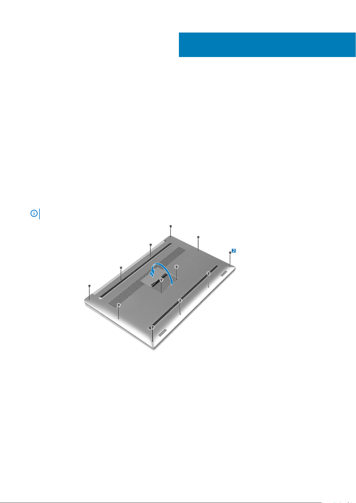
2. Close the display and turn the computer over.
3. Turn the system badge flap over (1) and then remove the screws that secure the base cover to the computer (2).
2
NOTE:
4. Pry the edges base cover and lift it to remove it from computer .
Use a Torx #5 screwdriver for the base screws and a Philips screwdriver for the screws inside the badge flap.
Removing and installing components 7
Page 8

Installing the Base Cover
1. Place the base cover on the computer and snap it in place.
2. Tighten the screws to secure the base cover to the computer.
NOTE:
screws.
3. Turn the system badge flap over and snap it in place.
4. Follow the procedures in After Working Inside Your Computer.
Ensure you use a Torx #5 screwdriver for the base screws and a Philips screwdriver for the system badge
Removing the Battery
NOTE:
the A/C adapter from the system (while the system is turned on) to allow the system to drain the battery.
1. Follow the procedures in Before Working Inside Your Computer.
2. Remove the base cover.
3. Perform the following steps to remove the battery:
a) Disconnect the battery cable from the system board [1].
b) Remove the screws that secure the battery to the computer [2].
c) Lift the battery off the computer [3].
• Do not apply pressure to the surface of the battery
• Do not bend
• Do not use tools of any kind to pry on or against the battery
• If a battery cannot be removed within the constraints above, please contact Dell technical support
Discharge the battery as much as possible before removing from the system. This can be done by disconnecting
8
Removing and installing components
Page 9

Installing the Battery
1. Place and align the battery in the battery bay.
2. Tighten the screws that secure the battery to the computer.
3. Connect the battery cable to the system board.
4. Install the base cover.
5. Follow the procedures in After Working Inside Your Computer.
Removing the Hard Drive
1. Follow the procedures in Before Working Inside Your Computer.
2. Remove the:
a) base cover
b) battery
3. Perform the following steps to remove the hard-drive bracket from the computer:
a) Remove the screws securing the hard-drive bracket to the computer [1].
b) Lift the hard-drive bracket off the computer [2].
4. Perform the following steps to remove the hard-drive:
a) Disconnect the hard-drive cable from the system board [1].
b) Lift the hard drive off the computer [2].
Removing and installing components
9
Page 10
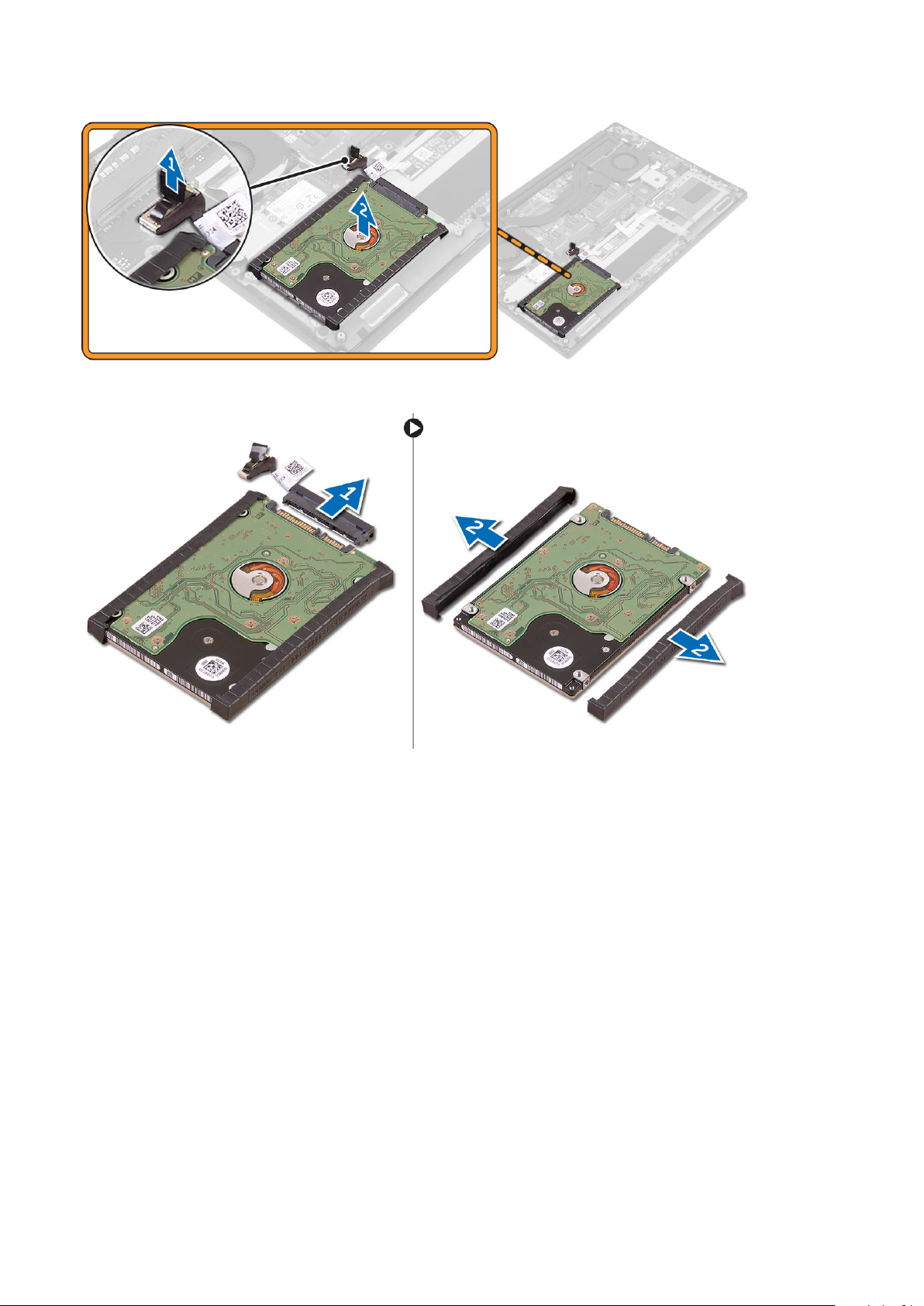
5. Remove the data-cable connector [1] and then slide out the two end brackets [2].
Installing the Hard Drive
1. Replace the hard-drive covers on the hard drive.
2. Connect the hard-drive interposer to the hard-drive assembly.
3. Place the hard-drive assembly on the palm-rest assembly.
4. Connect the hard-drive cable to the system board.
5. Align the screw holes on the hard-drive cage with the screw holes on the hard-drive assembly.
6. Replace the screws that secure the hard-drive cage to the palm-rest assembly.
7. Install the:
a) battery
b) base cover
8. Follow the procedures in After Working Inside Your Computer.
Removing the Solid-State Drive (half-length)
1. Follow the procedures in Before Working Inside Your Computer.
2. Remove the:
a) base cover
b) battery
10
Removing and installing components
Page 11
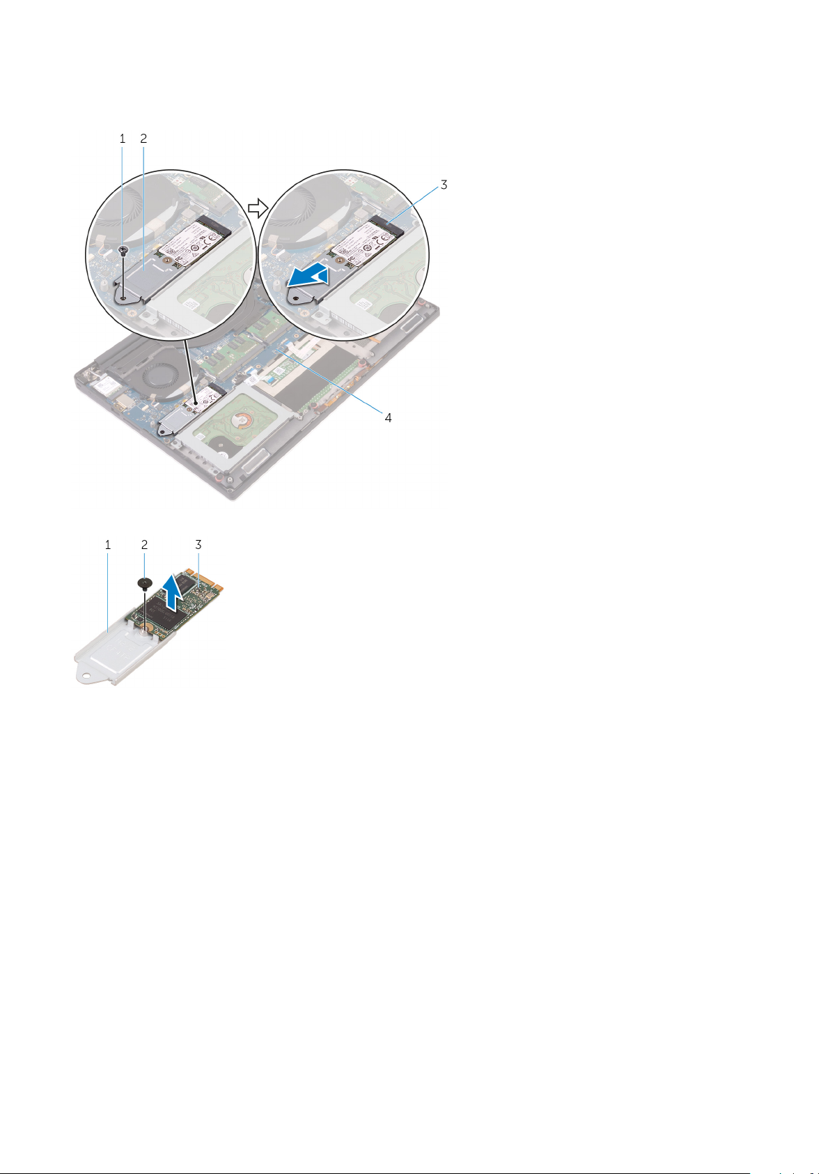
3. Remove the screw that secures the solid-state drive assembly to the system board [1, 2].
4. Lift and slide the solid-state drive assembly from the system board [3].
5. Remove the screw that secures the solid-state drive to the solid-state drive bracket [1, 2, 3].
6. Lift the solid-state drive off the solid-state drive bracket.
Installing the Solid-State Drive (half-length)
1. Align the screw hole on the solid-state drive bracket with the screw hole on the solid-state drive.
2. Replace the screw that secures the solid-state drive to the solid-state drive bracket.
3. Align the notches on the solid-state drive assembly with the tabs in the solid-state drive slot.
4. Slide the solid-state drive assembly at an angle into the solid-state drive slot.
5. Press the other end of the solid-state drive down and replace the screw that secures the solid-state drive to the system board.
6. Install the:
a) battery
b) base cover
7. Follow the procedures in After Working Inside Your Computer.
Removing the Solid-State Drive (full-length)
1. Follow the procedures in Before Working Inside Your Computer
2. Remove the:
a) base cover
b) battery
Removing and installing components
11
Page 12
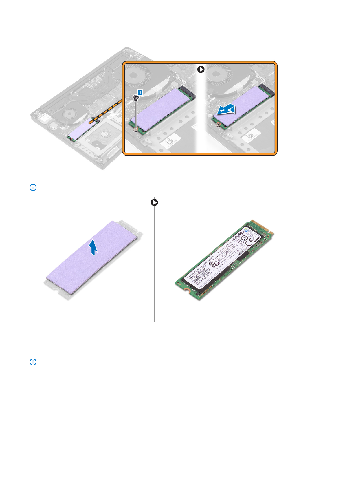
3. Remove the screw that secures the solid-state drive to the system board.
4. Remove the thermal pad from the SSD.
NOTE:
The thermal pad is applicable only for a PCIe SSD card.
Installing the Solid-State Drive (full-length)
1. Adhere the thermal pad to the solid-state drive.
NOTE:
2. Slide the solid-state drive at an angle into the solid-state drive slot.
3. Press the other end of the solid-state drive down and replace the screw that secures the solid-state drive to the system board.
4. Install the:
a) battery
b) base cover
5. Follow the procedures in After Working Inside Your Computer.
12
The thermal pad is applicable only for a PCIe SSD card.
Removing and installing components
Page 13
Removing the Speakers
1. Follow the procedures in Before Working Inside Your Computer.
2. Remove the:
a) base cover
b) battery
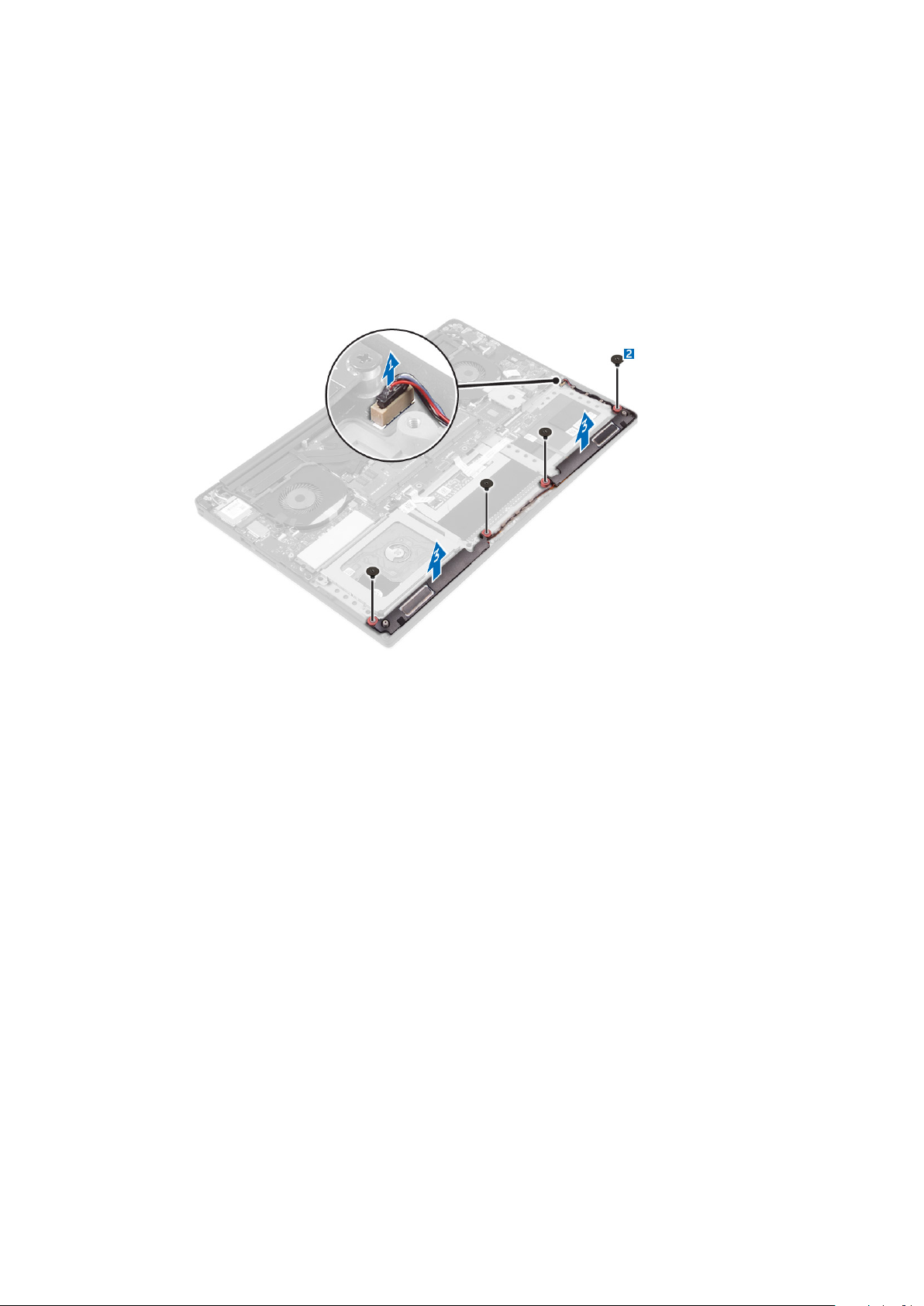
3. Perform the following steps to remove the speaker:
a) Disconnect the speaker cable from the system board [1].
b) Remove the screws that secure the speakers to the computer [2].
c) Lift the speakers, along with the speaker cable, off the computer [3].
Installing the Speakers
1. Using the alignment posts, place the speakers on the palm-rest assembly.
2. Replace the screws that secure the speakers to the palm-rest assembly.
3. Route the speaker cables through the routing guides on the palm-rest assembly.
4. Connect the speaker cable to the system board.
5. Install the:
a) battery
b) base cover
6. Follow the procedures in After Working Inside Your Computer.
Removing the WLAN Card
1. Follow the procedures in Before Working Inside Your Computer.
2. Remove the:
a) base cover
b) battery
3. Perform the following steps to remove the WLAN card:
a) Remove the screw to release the bracket that secures the WLAN card to the computer [1] and lift the bracket away from the
computer [2].
b) Disconnect the antenna cables from the WLAN card [3].
c) Slide and remove the WLAN card from its connector on the board [4].
Removing and installing components
13
Page 14

Installing the WLAN Card
1. Align the notch on the WLAN card with the tab on the WLAN-card connector on the I/O board.
2. Align the bracket which secures the WLAN card to the palmrest assembly.
3. Connect the antenna cables to the WLAN card.
CAUTION:
NOTE: The color of the antenna cables is visible near the tip of the cables. The antenna-cable color scheme for the
WLAN card supported by your computer is as follows:
Table 1. Antenna-Cable Color Scheme for the WLAN Card
Connectors on the WLAN card Antenna-cable color
Main (white triangle) white
Auxiliary (black triangle) black
Multiple input, multiple output (grey triangle) Grey (optional)
4. Tighten the screw to secure the bracket and the WLAN card to the palmrest assembly.
5. Install the:
a) battery
b) base cover
6. Follow the procedures in After Working Inside Your Computer.
To avoid damage to the WLAN card, do not place any cables under it.
Removing the Fans
1. Follow the procedures in Before Working Inside Your Computer.
2. Remove the:
a) base cover
b) battery
3. Perform the following steps to remove the left video-card fan:
a) Un-thread the LVDS cable from its restraints [1] and [2].
b) Disconnect the fan cable from the system board [3]
c) Remove the screws that secure the fan to the computer [4].
d) Lift the fan away from the computer [5].
14
Removing and installing components
Page 15

4. Perform the following steps to remove the right system fan:
a) Un-thread the LVDS cable from its restraints [1].
b) Disconnect the fan cable from the system board [2]
c) Remove the screws that secure the fan to the computer [3].
d) Lift the fan away from the computer [4].
Installing the Fans
1. Perform the following steps to install the system fan:
a) Align the screw holes on the left fan with the screw holes on the palm-rest assembly.
b) Connect the left fan cable to the system board.
c) Route the display cable through the routing guides on the left fan.
d) Replace the screws that secure the left fan to the system board.
e) Connect the right fan cable to the system board.
f) Route the touch-screen cable through the routing guides on the right fan.
g) Adhere the tape that secures the touch-screen cable to the right fan.
h) Connect the display cable to the system board.
i) Replace the screws that secure the right fan to the system board.
2. Follow the procedures in After Working Inside Your Computer.
Removing and installing components
15
Page 16

Removing the Heatsink
1. Follow the procedures in Before Working Inside Your Computer.
2. Remove the:
a) base cover
b) battery
3. Remove the screws that secure the heatsink to the system board.
4. Lift the heatsink off the computer.
Installing the Heatsink
1. Align the screw holes on the heatsink with the screw holes on the system board.
2. Replace the screws to secure the heatsink to the system board.
3. Install the:
a) battery
b) base cover
4. Follow the procedures in After Working Inside Your Computer.
16
Removing and installing components
Page 17

Removing the Memory Module(s)
1. Follow the procedures in Before Working Inside Your Computer.
2. Remove the:
a) base cover
b) battery
3. Pry the securing clips away from the memory module until it pops-up. Remove the memory module from its connector on the system
board.
Installing the Memory Module(s)
1. Insert the memory module into the memory socket.
2. Press the memory module down until it clicks into place.
NOTE:
3. Install the:
a) battery
b) base cover
4. Follow the procedures in After Working Inside Your Computer.
If you do not hear the click, remove the memory module and re-install it.
Removing the System Board
1. Follow the procedures in Before Working Inside Your Computer.
2. Remove the:
a) base cover
b) battery
c) fans
d) heatsink
e) SSD
f) memory modules
NOTE:
BIOS after you replace the system board.
NOTE: Before disconnecting the cables from the system board, note the location of the connectors so that you can
re-connect them correctly after you replace the system board.
Your computer’s Service Tag is located under the system badge flap. You must enter the Service Tag in the
Removing and installing components 17
Page 18

3. Remove the screw securing the metal bracket for the LVDS to the system board [1] and remove the bracket off the computer [2].
Then, disconnect the LVDS cable from the system board [3].
4. Slide out the connector latches to disconnect all the cables from the system board.
5. Perform the following steps to remove the system board from the computer:
a) Remove the screws that secure the system board to the computer [1].
b) Lift the system board off the computer [2].
18
Removing and installing components
Page 19

Installing the System Board
1. Align the system board on the computer.
2. Replace the screws that secure the system board to the palm-rest assembly.
3. Connect the power-adapter port cable, speaker cable, keyboard-control board cable, touch-pad cable, and touch-screen cable to the
system board.
4. Connect the display cable to the system board.
5. Align the screw hole on the display-cable bracket with the screw hole on the system board.
6. Follow the procedures in After Working Inside Your Computer.
Removing the Audio Daughter Board
1. Follow the procedures in Before Working Inside Your Computer.
2. Remove the:
a) base cover
b) battery
c) WLAN card
d) hard drive
e) SSD (half length)
f) SSD (full length)
g) fans
h) heatsink
i) memory modules
j) system board
3. Remove the two screws that secure the audio daughter board to the system board.
Removing and installing components
19
Page 20

a. system board
b. screws
4. Flip the system board over, then lift the audio daughter board from the system board.
a. audio daughter board
Installing the audio daughter board
1. Align the screw holes on the audio daughter board with the screw holes on the system board.
2. Flip the system board over, then replace the screws that secure the audio daughter board to the system board.
3. Install the:
a) system board
b) memory modules
c) heat-sink assembly
d) fans
e) solid-state drive (half-length)
f) solid-state drive (full-length)
g) hard drive
h) wireless card
i) battery
20
Removing and installing components
Page 21

j) base cover
4. Follow the procedures in After Working Inside Your Computer.
Removing the Keyboard
1. Follow the procedures in Before Working Inside Your Computer.
2. Remove the:
a) base cover
b) battery
c) fans
d) heatsink
e) SSD
f) memory modules
g) system board
3. Perform the following steps to disconnect the keyboard and backlight connectors from the computer.
a) Lift up the connector lock [1] and the disconnect the cables from the connectors [2].
b) Peel back the screw shields [3].
4. Un-route the LVDS cable [1] and then remove the screws that secure the keyboard to the computer [2].
5. Lift and remove the keyboard from the computer.
Removing and installing components
21
Page 22

Installing the Keyboard
1. Adhere the Mylar to the keyboard.
2. Align the screw holes on the keyboard with the screw holes on the palm-rest assembly.
3. Replace the screws that secure the keyboard to the palm-rest assembly.
4. Adhere the Mylar to the screws that secure the keyboard to the palm-rest assembly.
5. Connect the keyboard cable and keyboard-backlight cable to the keyboard-controls board.
6. Install the:
a) system board
b) hard drive
c) base cover
7. Follow the procedures in After Working Inside Your Computer.
Removing the Display Assembly
1. Follow the procedures in Before Working Inside Your Computer.
2. Remove the:
a) base cover
b) battery
3. Perform the following steps:
a) Disconnect the left LVDS cable [1].
b) Remove the screw securing the metal bracket [2] and lift the bracket off the computer [3].
c) Disconnect the right LVDS cable from the system board [4].
22
Removing and installing components
Page 23

4. Place the computer at the edge of a table as shown and remove the screws [1] securing the display assembly to the computer. Then,
lift the display assembly off the computer [2].
Installing the Display Assembly
1. Place the palm-rest assembly at the edge of the table with the speakers facing away from the edge.
2. Align the screw holes on the palm-rest assembly with the screw holes on the display hinges.
Removing and installing components
23
Page 24

3. Replace the screws that secure the display hinges to the palm-rest assembly.
4. Adhere the tape and route the touch-screen cable through the routing guides on the fan.
5. Connect the touch-screen cable and display cable to the system board.
6. Replace the screw that secures the display-cable bracket to the system board.
7. Follow the procedures in After Working Inside Your Computer.
Removing the DC-in Connector
1. Follow the procedures in Before Working Inside Your Computer.
2. Remove the:
a) base cover
b) battery
3. Perform the following steps to remove the I/O board:
a) Disconnect the DC-in cable from the system board [1].
b) Remove the screw that secures the DC-in cable to the computer.
c) Remove the DC-in connector from the computer.
Installing the DC-in Adapter Port
1. Place the DC-in adapter port into the slot on the palm-rest assembly.
2. Route the power-adapter port cable through its routing guides on the palm-rest assembly.
3. Replace the screw that secures the power-adapter port to the palm-rest assembly.
4. Connect the power-adapter port cable to the system board.
5. Install the:
a) battery
b) base cover
6. Follow the procedures in After Working Inside Your Computer.
Removing the antenna cover
1. Follow the procedures in Before Working Inside Your Computer.
2. Remove the:
a) base cover
b) battery
c) WLAN Card
24
Removing and installing components
Page 25

d) display assembly
3. Carefully turn the display hinges at an angle.
Figure 1. Turning the display hinge
a. display assembly
b. display hinges (2)
4. Slide and lift the antenna cover away from the display assembly.
Figure 2. Removing the antenna cover
a. display assembly
b. antenna cover
Installing the antenna cover
1. Replace the antenna cover on the display assembly.
2. Turn the display hinges to the normal position.
3. Install the:
a) display assembly
b) wireless card
c) battery
d) base cover
4. Follow the procedures in After Working Inside Your Computer.
Removing and installing components
25
Page 26

Removing the display hinges
1. Follow the procedures in Before Working Inside Your Computer.
2. Remove the:
a) base cover
b) battery
c) WLAN Card
d) display assembly
e) antenna cover
3. Peel off the tape to access the screws on the display hinges.
a. tape
b. display hinges (2)
4. Remove the screws that secure the display hinges to the display assembly.
5. Carefully lift the display hinges off the display assembly.
a. screws (6)
b. display hinges (2)
Installing the display hinges
1. Align the screw holes on the display hinges with the screw holes on the display assembly.
26
Removing and installing components
Page 27

2. Replace the screws that secure the display hinges to the display assembly.
3. Adhere the tape to the display hinges.
4. Install the:
a) antenna cover
b) display assembly
c) wireless card
d) battery
e) base cover
5. Follow the procedures in After Working Inside Your Computer.
Removing the antenna module
1. Follow the procedures in Before Working Inside Your Computer.
2. Remove the:
a) base cover
b) battery
c) wireless card
d) display assembly
e) antenna cover
f) display hinges
3. Peel the tape that covers the antenna cables.
4. Remove the screws that secure the antenna module to the display assembly.
5. Lift the antenna module away from the display assembly.
tape 2. antenna cable
1.
3. screws (4) 4. antenna module
5. display assembly
Installing the antenna module
1. Align the screw holes on the antenna module with the screw holes on the display assembly.
2. Replace the screws that secure the antenna module to the display assembly.
3. Adhere the tape that covers the antenna cable.
4. Install the:
a) display hinges
Removing and installing components
27
Page 28

b) antenna cover
c) display assembly
d) wireless card
e) battery
f) base cover
5. Follow the procedures in After Working Inside Your Computer.
Removing the palm-rest assembly
1. Follow the procedures in Before Working Inside Your Computer.
2. Remove the:
a) base cover
b) battery
c) memory modules
d) Follow the procedure from step 1 to step 4 in “Removing the hard drive
e) wireless card
f) speakers
g) heat-sink
h) fans
i) display assembly
j) power-adapter port
k) system board
l) keyboard
After performing the steps in the prerequisites we are left with the palm-rest assembly.
a. palm-rest assembly
Installing the palm-rest assembly
1. Place the palm-rest assembly on a clean and flat surface.
2. Install the:
a) keyboard
b) system board
c) power-adapter port
d) display assembly
e) fans
f) heat-sink assembly
g) speakers
h) wireless card
i) Follow the procedure from step 3 to step 6 in “Replacing the hard drive”.
28
Removing and installing components
Page 29

j) memory modules
k) battery
l) base cover
3. Follow the procedures in After Working Inside Your Computer.
Removing and installing components 29
Page 30

3
System setup
System setup enables you to manage your tabletdesktopnotebook hardware and specify BIOS level options. From the System setup, you
can:
• Change the NVRAM settings after you add or remove hardware
• View the system hardware configuration
• Enable or disable integrated devices
• Set performance and power management thresholds
• Manage your computer security
Topics:
• Boot Sequence
• Navigation keys
• System Setup Options
• Updating the BIOS in Windows
• System and setup password
Boot Sequence
Boot Sequence allows you to bypass the System Setup–defined boot device order and boot directly to a specific device (for example:
optical drive or hard drive). During the Power-on Self Test (POST), when the Dell logo appears. you can:
• Access System Setup by pressing F2 key
• Bring up the one-time boot menu by pressing F12 key
The one-time boot menu displays the devices that you can boot from including the diagnostic option. The boot menu options are:
• Removable Drive (if available)
• STXXXX Drive
NOTE:
• Optical Drive (if available)
• Diagnostics
NOTE:
The boot sequence screen also displays the option to access the System Setup screen.
XXX denotes the SATA drive number.
Choosing Diagnostics, will display the ePSA diagnostics screen.
Navigation keys
NOTE:
restart the system.
Keys Navigation
Up arrow Moves to the previous field.
Down arrow Moves to the next field.
Enter Selects a value in the selected field (if applicable) or follow the link in the field.
Spacebar Expands or collapses a drop‐down list, if applicable.
Tab Moves to the next focus area.
For most of the System Setup options, changes that you make are recorded but do not take effect until you
NOTE: For the standard graphics browser only.
30 System setup
Page 31

Keys Navigation
Esc Moves to the previous page until you view the main screen. Pressing Esc in the main screen displays a message
that prompts you to save any unsaved changes and restarts the system.
System Setup Options
NOTE: Depending on your computer and its installed devices, the items listed in this section may or may not appear.
Table 2. Main
Option Description
System Time/Date Allows you to set the date and time.
BIOS Version Displays the BIOS version.
Product Name Displays the product name.
Dell Precision M3800 (Default Setting)
Service Tag Displays the service tag.
Asset Tag Displays the asset tag.
None (Default Setting)
CPU Type Displays the CPU type.
CPU Speed Displays the CPU speed.
CPU ID Displays the CPU ID.
CPU Cache Displays the sizes of the CPU caches.
Fixed HDD Displays the type and size of the HDD.
WDC WD10SPCX-75HWSTO (1000 GB) (Default Setting)
mSATA Device Displays the type and size of the mSATA device.
AC Adapter Type Displays the type of the AC adapter.
None (Default Setting)
System Memory Displays the size of the system memory.
Extended Memory Displays the size of the extended memory.
Memory Speed Displays the speed of the memory.
Keyboard Type Displays the type of keyboard.
Backlite (Default Setting)
Table 3. Advanced
Option Description
Intel (R) SpeedStep (TM) Allows you to enable or disable the Intel (R) SpeedStep (TM) feature.
Enabled (Default Setting)
Virtualization This option specifies whether a Virtual Machine Monitor (VMM) can utilize the additional hardware
capabilities provided by Intel Virtualization technology. Allows you to enable or disable the
Virtualization feature.
Enabled (Default Setting)
USB Emulation Allows you to enable or disable the USB Emulation feature.
Enabled (Default Setting)
USB PowerShare Allows you to enable or disable the USB PowerShare feature.
System setup 31
Page 32

Option Description
Enabled (Default Setting)
USB Wake Support This option allows you to enable USB devices to wake the system from Standby.
Disable(Default Setting)
SATA Operation Displays the SATA Operation information.
Adapter Warnings Allows you to enable or disable the adapter warnings feature.
Multimedia Key Behaviour
Battery Health Displays the battery health information.
Battery Charge Configuration
Miscellaneous Devices Allows you enable or disable the various on board devices. The options are:
Table 4. Security
Option Description
Unlock Setup Status
Admin Password Status Displays the status of the admin password.
Function Key (Default Setting)
Adaptive (Default Setting)
• External USB Ports - Enabled (Default Setting)
• USB Debug - Disabled (Default Setting)
Unlocked (Default Setting)
Default Setting: Not set
System Password Status Displays the status of the system password.
Default Setting: Not set
HDD Password Status Displays the status of the system password.
Default Setting: Not set
Asset Tag Allows you to set the asset tag.
Admin Password Allows you to set, change, or delete the administrator (admin) password.
NOTE: You must set the admin password before you set the system or hard drive
password.
NOTE: Successful password changes take effect immediately.
NOTE: Deleting the admin password automatically deletes the system password
and the hard drive password.
NOTE: Successful password changes take effect immediately.
System Password Allows you to set, change or delete the system password.
NOTE: Successful password changes take effect immediately.
HDD Password Allows you to set, change or delete the administrator password.
Password Change Allows you to enable or disable permissions to set a System password and a Hard Drive
password when the admin password is set.
Default Setting: Permitted
Computrace Allows you to activate or disable the optional Computrace software The options are:
• Deactivate (Default Setting)
• Activate
NOTE: The Activate and Disable options will permanently activate or disable the
feature and no further changes will be allowed.
32 System setup
Page 33

Option Description
TPM Security This option lets you control whether the Trusted Platform Module (TPM) in the system is
enabled and visible to the operating system. When disabled the BIOS will not turn On the TPM
During POST. The TPM will be non-functional and invisible to the operating system. When
enabled, the BIOS will turn On the TPM during POST so that it can be used by the operating
system. This option is
NOTE: Disabling this option does not change any settings you may have made to
the TPM, nor does it delete or change any information or keys you may have
stored there. It simply turns Off the TPM so that it cannot be used. When you reenable this option, the TPM will function exactly as it did before it was disabled.
NOTE: Changes to this option take effect immediately.
Table 5. Boot
Option Description
Boot List Option
Secure Boot This option enables or disables the Secure Boot feature.
Load Legacy Option ROM This option enables or disables the Load Legacy Option ROM feature.
Default Setting: Legacy
• Disabled (Default Setting) - Windows 7
• Enabled - Windows 8.1
• Enabled (Default Setting) - Windows 7
• Disabled - Windows 8.1
Enable by default.
Set Boot Priority Allows you to change the order in which the computer attempts to find an operating system:
• 1 st Boot Priority [ CD/DVD/CD-RW Drive]
• 2nd Boot Priority [Network]
• 3rd Boot Priority [mini SSD]
• 4th Boot Priority [USB Storage Device
• 5th Boot Priority [Hard Drive]
• 6th Boot Priority [Diskette Drive]
Table 6. Exit
Option Description
Save Changes and Reset Allows you to save the changes you made.
Discard Changes and Reset Allows you to discard the changes you made.
Restore Defaults Allows you to restore the default options.
Discard Changes Allows you to discard the changes you made.
Save Changes Allows you to save the changes you made.
Updating the BIOS in Windows
It is recommended to update your BIOS (System Setup), on replacing the system board or if an update is available. For laptops, ensure
that your computer battery is fully charged and connected to a power outlet
NOTE:
BIOS update is completed.
1. Restart the computer.
2. Go to Dell.com/support.
• Enter the Service Tag or Express Service Code and click Submit.
• Click Detect Product and follow the instructions on screen,
3. If you are unable to detect or find the Service Tag, click the Choose from all products.
If BitLocker is enabled, it must be suspended prior to updating the system BIOS, and then re-enabled after the
System setup
33
Page 34

4. Choose the Products category from the list.
NOTE: Choose the appropriate category to reach the product page
5. Select your computer model and the Product Support page of your computer appears.
6. Click Get drivers and click Drivers and Downloads.
The Drivers and Downloads section opens.
7. Click Find it myself.
8. Click BIOS to view the BIOS versions.
9. Identify the latest BIOS file and click Download.
10. Select your preferred download method in the Please select your download method below window, click Download File.
The File Download window appears.
11. Click Save to save the file on your computer.
12. Click Run to install the updated BIOS settings on your computer.
Follow the instructions on the screen.
NOTE: It is recommended not to update the BIOS version for more than 3 revisions. For example: If you want to update
the BIOS from 1.0 to 7.0, then install version 4.0 first and then install version 7.0.
System and setup password
You can create a system password and a setup password to secure your computer.
Password type
System password Password that you must enter to log on to your system.
Setup password Password that you must enter to access and make changes to the BIOS settings of your computer.
CAUTION: The password features provide a basic level of security for the data on your computer.
CAUTION: Anyone can access the data stored on your computer if it is not locked and left unattended.
NOTE: Your computer is shipped with the system and setup password feature is disabled.
Description
Assigning a system password and setup password
You can assign a new System Password only when the status is in Not Set.
To enter the system setup, press F2 immediately after a power-on or re-boot.
1. In the System BIOS or System Setup screen, select Security and press Enter.
The Security screen is displayed.
2. Select System Password and create a password in the Enter the new password field.
Use the following guidelines to assign the system password:
• A password can have up to 32 characters.
• The password can contain the numbers 0 through 9.
• Only lower case letters are valid, upper case letters are not allowed.
• Only the following special characters are allowed: space, (”), (+), (,), (-), (.), (/), (;), ([), (\), (]), (`).
3. Type the system password that you entered earlier in the Confirm new password field and click OK.
4. Press Esc and a message prompts you to save the changes.
5. Press Y to save the changes.
The computer reboots.
34
System setup
Page 35

Deleting or changing an existing system and/or setup password
Ensure that the Password Status is Unlocked (in the System Setup) before attempting to delete or change the existing System and/or
Setup password. You cannot delete or change an existing System or Setup password, if the Password Status is Locked.
To enter the System Setup, press F2 immediately after a power-on or reboot.
1. In the System BIOS or System Setup screen, select System Security and press Enter.
The System Security screen is displayed.
2. In the System Security screen, verify that Password Status is Unlocked.
3. Select System Password, alter or delete the existing system password and press Enter or Tab.
4. Select Setup Password, alter or delete the existing setup password and press Enter or Tab.
NOTE: If you change the System and/or Setup password, re-enter the new password when promoted. If you delete
the System and/or Setup password, confirm the deletion when promoted.
5. Press Esc and a message prompts you to save the changes.
6. Press Y to save the changes and exit from System Setup.
The computer reboots.
System setup 35
Page 36

4
Diagnostics
If you experience a problem with your computer, run the ePSA diagnostics before contacting Dell for technical assistance. The purpose of
running diagnostics is to test your computer's hardware without requiring additional equipment or risking data loss. If you are unable to fix
the problem yourself, service and support personnel can use the diagnostics results to help you solve the problem.
Topics:
• Enhanced Pre-Boot System Assessment (ePSA) diagnostics
• Device Status Light
Enhanced Pre-Boot System Assessment (ePSA) diagnostics
The ePSA diagnostics (also known as system diagnostics) performs a complete check of your hardware. The ePSA is embedded with the
BIOS and is launched by the BIOS internally. The embedded system diagnostics provides a set of options for particular devices or device
groups allowing you to:
• Run tests automatically or in an interactive mode
• Repeat tests
• Display or save test results
• Run thorough tests to introduce additional test options to provide extra information about the failed device(s)
• View status messages that inform you if tests are completed successfully
• View error messages that inform you of problems encountered during testing
CAUTION:
invalid results or error messages.
NOTE: Some tests for specific devices require user interaction. Always ensure that you are present at the computer
terminal when the diagnostic tests are performed.
Use the system diagnostics to test only your computer. Using this program with other computers may cause
Device Status Light
Table 7.
Icon Description
Turns on when you turn on the computer.
36 Diagnostics
Page 37

Technical Specifications
NOTE: Offerings may vary by region. For more information regarding the configuration of your computer, click Start
(Start icon) > Help and Support, and then select the option to view information about your computer.
Table 8. System Information
Feature Specification
System Chipset Mobile Intel HM170 Express Chipset / Intel CM236
DMA Channels two VT-d DMA remap engines
Interrupt Levels Intel 64 and IA-32 Architecture
BIOS Chip (NVRAM) 8 MB
Table 9. Processor
Feature Specification
Processor type 6th Generation Intel Core i3/ 6th Generation Intel Quad Core i5/ 6th Generation
Intel Quad Core i7
L1 cache up to 256 KB cache depending on processor type
L2 cache up to 1024 KB cache depending on processor type
L3 cache up to 6144 KB cache depending on processor type
5
Table 10. Memory
Feature Specification
Type DDR4
Speed 2133 MHz
Connectors 2 SoDIMM Sockets
Capacity 8 GB, 16 GB, and 32GB
Minimum Memory 8 GB
Maximum memory 32 GB
Table 11. Video
Feature Specification
Type
Discrete NVIDIA GeForce GTX 960M
Integrated Intel HD Graphics 530
Data bus PCIE x16, Gen3
Memory
Discrete Up to 2 GB GDDR5
Integrated Shared system memory
Technical Specifications 37
Page 38

Table 12. Audio
Feature Specification
Integrated dual-channel High-Definition audio
Table 13. Communication
Feature Specification
Network adapter Ethernet via USB-to-Ethernet Dongle provided in box.
NOTE: No RJ45 (10/100/1000Base-T, IPv6) provided.
Wireless
Table 14. Ports and Connectors
Feature Specification
Audio
USB 3.0
Video
Memory card reader SD 4.0
Table 15. Display
Feature Specification
Type 1920 x 1080 FHD
Size 15.6 inches FHD
• Wi-Fi 802.11ac
• Wi-Fi 802.11a/g/n
• Bluetooth 4.1
• Intel WiDi (optional)
• One headset port (headphone and microphone combo)
• two USB 3.0 ports with PowerShare
• One Thunderbolt 3 port with PowerShare (USB-C)
• one HDMI 1.4
3840 x 2160 UltraHD
15.6 inches UltraHD
Dimensions:
Height 194.50 mm (7.66 in)
Width 345.60 mm (13.61 in)
Diagonal 396.52 mm (15.61 in)
Active area (X/Y) 194.50 mm (7.66 in) x 345.60 mm (13.61 in) x 396.52 mm (15.61 in)
Maximum resolution 1920 X 1080 pixels / 3840 X 2160 pixels
Maximum Brightness 400 nits
Operating angle 0° (closed) to 135°
Refresh rate 60 Hz
Minimum viewing angles:
Horizontal 80/80
Vertical 80/80
38 Technical Specifications
Page 39

Table 16. Keyboard
Feature Specification
Number of keys
Layout QWERTY/AZERTY/Kanji
Table 17. Touchpad
Feature Specification
Active Area:
X-axis 105 mm
Y-axis 80 mm
Table 18. Camera
Feature Specification
Type HD Camera / Digital Array Microphone
Still Resolution 0.92 megapixels (Maximum)
Video Resolution 1280 x 720 pixels (HD) at 30 frames per second (Maximum)
Diagonal 74 degrees
• United States: 80 keys
• United Kingdom: 81 keys
• Brazil: 81 keys
• Japan: 84 keys
Table 19. Storage
Feature Specification
Storage:
Storage Interface SATA 3 Gbps
SATA 6 Gbps
Drives configurations:
Hard Drives (optional) one internal 2.5 inch SATA HDD (supports Intel Smart Response Technology)
Solid State Drives (optional) one Solid State Drive (SSD), with Intel Cache support
Size: 512 GB and 1 TB
Table 20. Battery
Feature Specification
Type Li-polymer 3-cell (56 Whr) / 6-cell (84 Whr)
Dimensions :
56 Whr :
Depth 223.20 mm (8.79 in)
Height 7.20 mm (0.28 in)
Width 71.80 mm (2.83 in)
Weight 0.54 lb (0.24 kg)
84 Whr :
Depth 330.50 mm (13.01 in)
Height 7.20 mm (0.28 in)
Width 71.80 mm (2.83 in)
Technical Specifications 39
Page 40

Feature Specification
Weight 0.76 lb (0.34 kg)
Voltage 11.4 V
Life span 300 discharge/charge cycles
Temperature range:
Operating (approximate)
Non-operating –40 °C to 65 °C (–40 °F to 149 °F)
Coin-cell battery ML1220
Table 21. AC Adapter
Feature Specification
Input voltage 100 VAC to 240 VAC
Input current (maximum) 1.80 A
Input frequency 50 Hz to 60 Hz
Output power 130 W
Output current 6.67 A
Rated output voltage 19.50 VDC
Dimensions:
Height 22 mm (0.86 inches)
Width 66 mm (2.59 inches)
Depth 143 mm (5.62 inches)
Temperature range:
Operating 0 °C to 40 °C (32 °F to 104 °F)
Non Operating –40 °C to 70 °C (–40 °F to 158 °F)
• Charge : 0 °C to 50 °C (32 °F to 158 °F)
• Discharge: 0 °C to 70 °C (32 °F to 122 °F)
• Operating: 0 °C to 35 °C (32 °F to 95 °F)
Table 22. Physical Dimensions
Physical Specification
Height: 17 mm (0.66 in)
Width 357 mm (14.06 in)
Depth 235 mm (9.27 in)
Weight (Minimum) 2 kg (4.41 lb)
Table 23. Environmental
Feature Specification
Temperature range:
Operating 0 °C to 40 °C (32 °F to 104°F)
Storage –40 °C to 70 °C (–40 °F to 158 °F)
Relative humidity (maximum):
Operating 10 % to 90 % (non-condensing)
Storage 10 % to 95 % (non-condensing)
Maximum vibration:
40 Technical Specifications
Page 41

Feature Specification
Operating 0.66 GRMS, 2 Hz - 600 Hz
Storage 1.3 GRMS, 2 Hz - 600 Hz
Maximum shock:
Operating 110 G, 2 ms
Non-operating 160 G, 2 ms
Altitude:
Operating
Storage 15.2 m to 10,668 m (–50 ft to 35,000 ft)
Airborne contaminant level G1 as defined by ISA-S71.04-1985
–15.2 m to 30482000 m (–50 to 10,0006560 ft)
Technical Specifications 41
Page 42

6
Contacting Dell
NOTE: If you do not have an active Internet connection, you can find contact information on your purchase invoice,
packing slip, bill, or Dell product catalog.
Dell provides several online and telephone-based support and service options. Availability varies by country and product, and some services
may not be available in your area. To contact Dell for sales, technical support, or customer service issues:
1. Go to Dell.com/support.
2. Select your support category.
3. Verify your country or region in the Choose a Country/Region drop-down list at the bottom of the page.
4. Select the appropriate service or support link based on your need.
42 Contacting Dell
 Loading...