

Page 1

Dell Precision™ WorkStation 530
MICROPROCESSOR REPLACEMENT
Remplacement du microprocesseur
Mikroprozessor-Austausch
Reemplazo del microprocesador
www.dell.com
support.dell.com
Page 2

Page 3

Contents
English . . . . . . . . . . . . . . . . . . . . . . . . . . . . . . . . . . . 5
Français . . . . . . . . . . . . . . . . . . . . . . . . . . . . . . . . . . . 15
Deutsch . . . . . . . . . . . . . . . . . . . . . . . . . . . . . . . . . . . 27
Español . . . . . . . . . . . . . . . . . . . . . . . . . . . . . . . . . . . 39
Page 4

Page 5

Dell Precision™ WorkStation 530
MICROPROCESSOR REPLACEMENT
www.dell.com
support.dell.com
Page 6

Notes, Notices, and Cautions
NOTE: A NOTE indicates important information that helps you make better
use of your computer.
NOTICE: A NOTICE indicates either potential damage to hardware or loss of
data and tells you how to avoid the problem.
CAUTION: A CAUTION indicates a potentially hazardous situation
which, if not avoided, may result in minor or moderate injury.
____________________
Information in this document is subject to change without notice.
© 2001 Dell Computer Corporation. All rights reserved.
Reproduction in any manner whatsoever without the written permission of
Dell Computer Corporation is strictly forbidden.
Trademarks used in this text:
Dell Computer Corporation.
Other trademarks and trade names may be used in this document to refer to either the entities
claiming the marks and names or their products. Dell Computer Corporation disclaims any
proprietary interest in trademarks and trade names other than its own.
May 2001 P/N 960CF Rev. A00
Dell
, the
DELL
logo, and
Dell Precision
are trademarks of
Page 7

Microprocessor Replacement
This document provides instructions on replacing the microprocessor
package on the Dell Precision™ WorkStation 530 computer.
NOTE: Dell recommends that only a technically knowledgeable person
perform this procedure.
NOTE: Dell recommends that you read this entire document before you begin.
For more information on procedures in this document, see the
and
User’s Guide
ResourceCD
reinstalled your operating system.
. You can access these documents from the
or from the User’s Guides icon on your desktop if you have not
Service Manual
Dell Precision
Precautionary Measures
CAUTION: Before you remove the computer cover, perform the
following steps in the sequence indicated.
1
Turn off your computer and any devices.
Disconnect your computer and devices from their power sources. Also,
disconnect any telephone or network lines from the computer.
Doing so reduces the potential for personal injury or shock.
2 If you are disconnecting a device from the computer or are removing a
component from the system board, wait 10 to 20 seconds after
disconnecting the computer from AC power before disconnecting the
device or removing the component to avoid possible damage to the
system board.
3 Wear a wrist grounding strap, and clip it to an unpainted metal
surface, such as the padlock loop on the back of the chassis. If a wrist
grounding strap is not available, touch any unpainted metal surface on
the back of the computer or on the computer chassis, such as the
power supply, to discharge any static charge from your body before
touching anything inside the computer. While you work, periodically
touch an unpainted metal surface on the computer chassis to dissipate
any static electricity that might harm internal components. Also avoid
touching components or contacts on a card and avoid touching pins on
a chip.
Microprocessor Replacement 5
Page 8

4 Verify that the standby power light on the system board is not on. If it
is on, you may need to wait 10 to 30 seconds for it to go out.
Microprocessor Installation Guidelines
• A voltage regulator module (VRM) must be installed for each
microprocessor installed. To locate the VRM and microprocessor
sockets, see "System Board Components" or "Interior Service Label" in
your User’s Guide.
• For single-processor operations, the processor must be installed in
socket 0 and the VRM must be installed in connector 0. Processor
www.dell.com | support. dell.com
socket 1 and VRM connector 1 must be empty. To locate these
components, see "System Board Components" or "Interior Service
Label" in your User’s Guide .
• For dual-processor operations, both processor sockets and both VRM
connectors must be populated.
• For dual-processor operations, the two processors and the two VRMs
must be identical. If the processors do not match, you receive a system
message, the diagnostic lights indicate an error, and the computer may
not start. If the VRMs do not match, the diagnostic lights will indicate
an error.
• If installing a Dell™ processor upgrade kit for either single or dual
processors, remove and discard the original VRM(s). Then install the
VRM(s) from the upgrade kit. If you are not installing a processor
upgrade kit from Dell, reuse the original VRM(s).
• If installing a Dell processor upgrade kit for either single or dual
processors, remove and discard the original heat sink(s) and securing
clips. Then install the heat sink(s) and securing clips from the upgrade
kit. If you are not installing a processor upgrade kit from Dell, reuse the
original heat sink(s) and securing clips.
6 Microprocessor Replacement
Page 9

Upgrading the Microprocessor(s)
. NOTE: Dell recommends that only a technically knowledgeable person
perform this procedure.
CAUTION: The processor can get very hot during normal
operation. Be sure that the processor has had sufficient time to
cool before you touch it.
CAUTION: Before you perform this procedure, see “Precautionary
Measures."
NOTICE: Before disconnecting a device from the computer, wait 10 to
20 seconds after disconnecting the computer from its electrical outlet. Before
removing a component from the system board, verify that the standby power
light on the system board has turned off. To locate this light, see "System Board
Components" or "Interior Service Label"
Remove the microprocessor airflow shroud:
1
a Lay the computer on its right side.
b Open the computer cover.
c Press down and back on the indentations at the top corners of the
shroud.
The top anchor tabs will disengage from the chassis anchor slots.
n your
i
User’s Guide
.
Microprocessor Replacement 7
Page 10
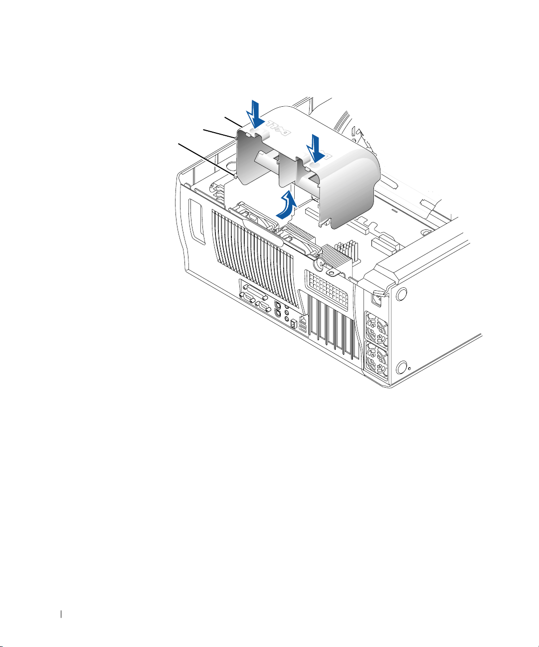
Removing the Microprocessor Airflow Shroud
airflow shroud
top anchor tabs (2)
bottom anchor tabs (2)
www.dell.com | support. dell.com
d Lift the airflow shroud out of the chassis.
2 Remove the microprocessor heat sink:
a For each of the metal clips that secure the heat sink to the
b Lift the heat sink away from the microprocessor.
8 Microprocessor Replacement
microprocessor, press down on the clip’s latch to release it from
the heat-sink retention base. Then lift the clip away from the heat
sink.
Page 11
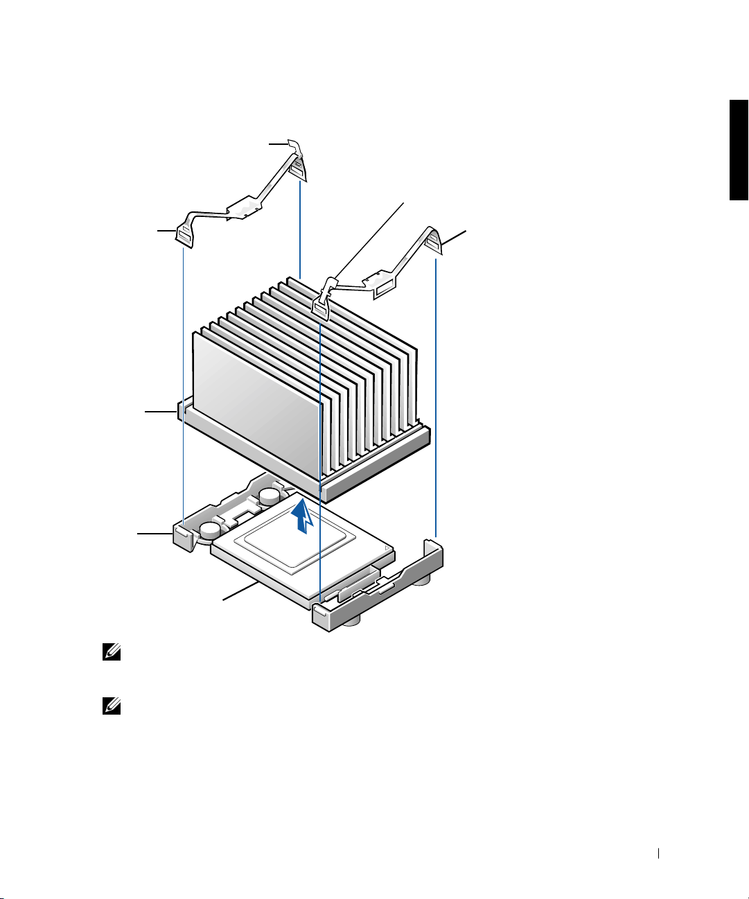
Removing the Microprocessor Heat Sink
g
latch
latch
securing clip
heat sink
retention
base
microprocessor socket
securin
clip
NOTE: If you are upgrading your microprocessor, you may want to keep
the original microprocessor, heat sink, and securing clips for future
troubleshooting.
NOTE: Your microprocessor upgrade kit should include a replacement
microprocessor, heat sink, and two replacement securing clips.
Remove the microprocessor from its connector.
3
Your microprocessor uses a zero insertion force (ZIF) socket with a
lever-type handle that secures or releases the microprocessor.
Microprocessor Replacement 9
Page 12
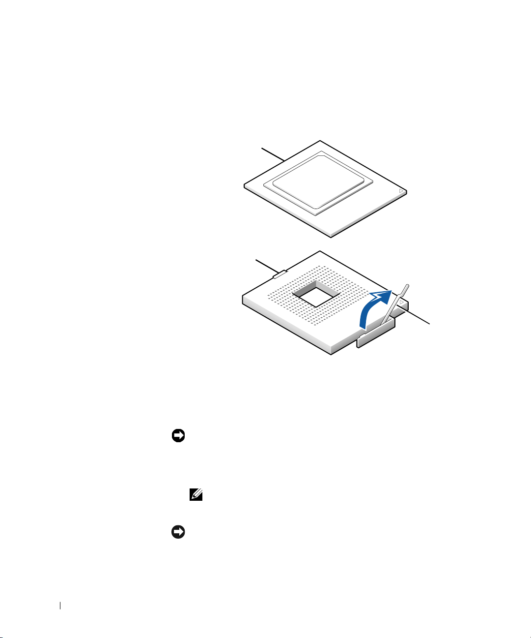
To remove the microprocessor, pull the socket lever up until the
microprocessor is released. Then remove the microprocessor from the
socket.
Removing the Microprocessor
microprocessor
www.dell.com | support. dell.com
microprocessor socket
socket lever
4
Install the new microprocessor in the socket:
a Ensure that the lever on the microprocessor socket is fully
NOTICE: When you place the microprocessor in the socket, ensure that the
microprocessor aligns properly with the socket. To avoid damage, you must
position the microprocessor correctly in the socket.
b Align pin 1 of the new microprocessor with pin 1 of the socket.
NOTICE: The microprocessor pins are delicate. To avoid damage, ensure that
the microprocessor aligns properly with the socket, and do not use excessive
force when installing the processor.
10 Microprocessor Replacement
extended to the release position.
NOTE: Pin 1 of the microprocessor is indicated by a small triangle in one
corner of the microprocessor. Pin 1 of the socket is indicated by a small
triangle in one corner of the socket. See "Installing the Microprocessor."
Page 13
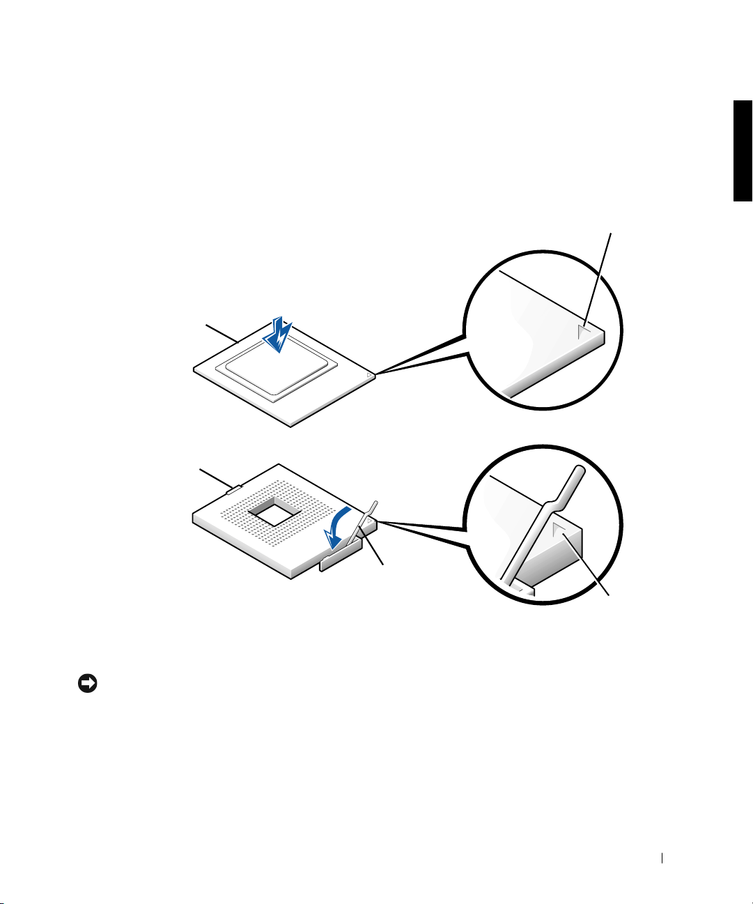
c Carefully set the microprocessor in the socket and press it down
lightly to seat it.
d Rotate the socket lever back toward the socket until it snaps into
place, securing the microprocessor.
Installing the Microprocessor
microprocessor
microprocessor socket
microprocessor
pin-1 indicator
socket lever
5 Install the replacement microprocessor heat sink:
NOTICE: Remove the film covering only when you are ready to replace the
heat sink. Once the film covering has been removed, lay the heat sink down
with the thermal grease facing upward. Do not lay the heat sink down with the
thermal grease touching the work surface.
a Remove the film covering the thermal grease on the bottom of the
heat sink.
socket pin-1
indicator
Microprocessor Replacement 11
Page 14

NOTICE: Carefully align the heat sink with the retention base before making
contact with the base to help avoid spreading the thermal grease to other
components.
b Lower the heat sink to the microprocessor so that the heat sink fits
in the heat sink retention base.
c For each of the replacement metal clips that secure the heat sink
to the microprocessor, fit the end of the clip that does not have the
latch to the heat sink retention base. Then, press down on the
clip’s latch to secure the clip to the heat sink retention base (see
"Removing the Microprocessor Heat Sink").
www.dell.com | support. dell.com
6 Install the airflow shroud:
a Insert the bottom anchor tabs of the shroud into the chassis
anchor slots.
b Press the shroud toward the chassis until the top anchor tabs on
the shroud snap securely into place. See "Removing the
Microprocessor Airflow Shroud."
7 Close the computer cover.
8 Stand the computer upright.
9 Reconnect the computer to the electrical outlet, and turn it on.
NOTE: If enabled, the Chassis Intrusion option will cause the following
message to be displayed at the next system start-up:
ALERT! Cover was previously removed.
Enter system setup, and confirm that the correct microprocessor speed
10
appears in the top left corner of the screen. Also, confirm that the top
line in the System Data area correctly identifies the new
microprocessor.
11 Exit system setup, turn off the computer, and attach the devices to the
computer and electrical outlets.
NOTE: For more information about system setup see your
User’s Guide
.
12 Microprocessor Replacement
Page 15

Dell Precision™ WorkStation 530
REMPLACEMENT DU MICROPROCESSEUR
www.dell.com
support.dell.com
Page 16

Remarques, avis et précautions
REMARQUE : Une REMARQUE indique une information importante qui
peut vous aider à mieux utiliser votre ordinateur.
AVIS : Un AVIS vous avertit d’un risque de dommage matériel ou de perte de
données et vous indique comment éviter le problème.
PRÉCAUTION : Une PRÉCAUTION vous avertit d’une situation
qui, si elle n’est pas évitée, peut entraîner des blessures plus ou
moins graves.
____________________
Les informations contenues dans ce document sont sujettes à modification sans préavis.
© 2001 Dell Computer Corporation. Tous droits réservés.
Toute reproduction, sous quelque forme que ce soit, sans l'autorisation écrite de
Dell Computer Corporation, est strictement interdite.
Marques utilisées dans ce texte :
Dell Computer Corporation.
D’autres marques et noms commerciaux peuvent être utilisés dans ce document pour faire
référence aux entités se réclamant de ces marques et de ces noms ou à leurs produits.
Dell Computer Corporation dénie tout intérêt propriétaire vis-à-vis des marques et des noms
commerciaux autres que les siens.
Mai 2001 P/N 960CF Rév. A00
Dell
, le logo
DELL
et
Dell Precision
sont des marques de
Page 17

Remplacement du microprocesseur
Ce document fournit des instructions sur la remise en place de l'assemblage
du microprocesseur sur l'ordinateur Dell Precision™ WorkStation 530.
REMARQUE : Dell recommande que seul un technicien compétent effectue
cette procédure.
REMARQUE : Dell vous conseille de lire le document d'un bout à l'autre
avant de commencer. Pour plus d'informations sur les procédures décrites
dans ce document, reportez-vous au
Vous pouvez accéder à ces documents à partir du cédérom
ResourceCD
réinstallé votre système d'exploitation.
ou de l'icône Guides d'utilisation du bureau si vous n'avez pas
guide technique
et au
Guide d'utilisation
Dell Precision
.
Mesures de précaution
PRÉCAUTION : Avant de retirer le capot de l'ordinateur, effec-
tuez les étapes suivantes dans l'ordre indiqué.
1
Éteignez votre ordinateur et ses périphériques.
Débranchez votre ordinateur et ses périphériques de leurs sources
d'alimentation. Débranchez également toutes les lignes de téléphone
et de réseau de l'ordinateur.
Cela diminuera le risque de blessure ou de choc.
2 Si vous déconnectez un périphérique de l'ordinateur ou que vous reti-
rez un composant de la carte système, patientez de 10 à 20 secondes
après avoir débranché l'ordinateur de sa source d'alimentation en CA
avant de le faire pour éviter d'endommager la carte système.
3 Portez un bracelet de mise à la terre et accrochez-le à une surface
métallique non peinte, telle que la boucle pour cadenas située à
l'arrière du châssis. Si aucun bracelet de mise à la terre n'est disponible,
touchez une surface métallique non peinte à l'arrière de l'ordinateur ou
sur le châssis de l'ordinateur, telle que le bloc d'alimentation, pour
décharger la charge statique de votre corps avant de toucher des éléments situés à l'intérieur de l'ordinateur. Pendant votre travail à
Remplacement du microprocesseur 15
Page 18

l’intérieur de l’ordinateur, touchez périodiquement une surface métallique non peinte sur le châssis, pour dissiper toute électricité statique
qui pourrait endommager les composants internes. Évitez également
de toucher des composants ou des contacts sur une carte et des broches d'une puce.
4 Vérifiez que le voyant d'alimentation de veille de la carte système est
éteint. S'il est allumé, attendez qu'il s'éteigne, ce qui peut prendre de
10 à 30 secondes.
Consignes d'installation du
www.dell.com | support. dell.com
microprocesseur
• Un VRM (Voltage Regulator Module [module régulateur de tension])
doit être installé pour chaque microprocesseur installé. Pour repérer
les supports du VRM et du microprocesseur, reportez-vous à la section
« Composants de la carte système » ou « Étiquette interne de service »
de votre Guide d'utilisation.
• Pour les opérations à un seul processeur, le processeur doit être installé
dans le support 0 et le VRM doit être installé dans le connecteur 0. Le
support 1 du processeur et le connecteur 1 du VRM doivent être vides.
Pour repérer ces composants, reportez-vous à la section « Composants
de la carte système » ou « Étiquette interne de service » dans votre
Guide d'utilisation.
• Pour les opérations à deux processeurs, les deux supports des processeurs et les deux connecteurs des VRM doivent être occupés.
• Pour les opérations à deux processeurs, les deux processeurs et les deux
VRM doivent être identiques. Si les processeurs ne correspondent pas,
vous recevez un message système, les voyants de diagnostic indiquent
une erreur et l'ordinateur risque de ne pas démarrer. Si les VRM ne
correspondent pas, les voyants de diagnostic indiquent une erreur.
• Si vous installez un kit de mise à niveau de microprocesseur de Dell™
pour un ou deux processeurs, retirez et débarrassez-vous du ou des
VRM d'origine. Installez ensuite le ou les VRM du kit de mise à niveau.
Si vous ne réutilisez pas un kit de mise à niveau de microprocesseur de
Dell, réutilisez le ou les VRM d'origine.
16 Remplacement du microprocesseur
Page 19

• Si vous installez un kit de mise à niveau de microprocesseur de Dell
pour un ou deux processeurs, retirez et débarrassez-vous du ou des dissipateurs de chaleur et des clips de fixation d'origine. Installez ensuite
le ou les dissipateurs de chaleur et les clips de fixation du kit de mise à
niveau. Si vous n'installez pas un kit de mise à niveau de microprocesseur de Dell, réutilisez le ou les dissipateurs de chaleur et les clips de
fixation d'origine.
Mise à niveau du ou des
microprocesseurs
REMARQUE : Dell recommande que seul un technicien compétent effectue
cette procédure.
PRÉCAUTION : Le processeur peut devenir brûlant pendant
l'opération normale. Assurez-vous que le processeur a eu le temps
de refroidir avant de le toucher.
PRÉCAUTION : Avant d'effectuer cette procédure, reportez-vous
à la section « Mesures de précaution ».
AVIS : Avant de déconnecter un périphérique de l'ordinateur, patientez de
10 à 20 secondes après avoir après avoir débranché l'ordinateur de sa prise de
courant. Avant de retirer un composant de la carte système, vérifiez que le
voyant d'alimentation de veille de la carte système s'est éteint. Pour repérer ce
voyant, reportez-vous à la section « Composants de la carte système » ou «
Étiquette interne de service »
ns votre
da
Guide d'utilisation
.
Retirez le carénage de ventilation du microprocesseur :
1
a Couchez l'ordinateur sur son côté droit.
b Ouvrez le capot de l'ordinateur.
c Appuyez sur les parties creuses situées dans les coins supérieurs du
carénage.
Les languettes supérieures de fixation se dégagent des logements
de fixation du châssis.
Remplacement du microprocesseur 17
Page 20

Retrait du carénage de ventilation du microprocesseur
carénage de ventilation
languettes de
fixation (2) supérieures
languettes de fixation
(2) inférieures
www.dell.com | support. dell.com
d Soulevez le carénage de ventilation pour l'écarter du châssis.
2 Retirez le dissipateur de chaleur du microprocesseur :
a Pour chacun des clips métalliques qui fixent le dissipateur de cha-
leur au microprocesseur, appuyez sur le dispositif de blocage du
clip pour le libérer de la base de fixation du dissipateur de chaleur.
Soulevez ensuite le clip pour le retirer du dissipateur de chaleur.
b Soulevez le dissipateur de chaleur pour l'écarter du
microprocesseur.
18 Remplacement du microprocesseur
Page 21

Retrait du dissipateur de chaleur du microprocesseur
loquet
loquet
clip de fixation
dissipateur
de chaleur
base de
fixation
support du microprocesseur
clip de
fixation
REMARQUE : Si vous mettez votre microprocesseur à niveau, vous pou-
vez conserver le microprocesseur, le dissipateur de chaleur et les clips de
fixation d'origine pour un dépannage futur.
REMARQUE : Votre kit de mise à niveau du microprocesseur doit
inclure un microprocesseur, un dissipateur de chaleur de remplacement,
ainsi que deux clips de fixation de remplacement.
Remplacement du microprocesseur 19
Page 22

3 Retirez le microprocesseur de son connecteur.
Votre microprocesseur utilise un support ZIF (Zero Insertion Force
[à force d'insertion nulle]) avec une manette qui fixe ou dégage le
microprocesseur.
Pour retirer le microprocesseur, soulevez la manette du support jusqu'à
ce que le microprocesseur soit libéré. Retirez ensuite le microprocesseur de son support.
Retrait du microprocesseur
microprocesseur
www.dell.com | support. dell.com
support du
microprocesseur
4
Installez le nouveau microprocesseur dans le support :
a Vérifiez que la manette sur le support du microprocesseur est dans
la position de dégagement.
AVIS : Lorsque vous placez le microprocesseur dans le support, vérifiez que le
microprocesseur s'aligne correctement avec le support. Pour éviter tout dommage, vous devez placer le microprocesseur correctement dans le support.
b Alignez la broche 1 du nouveau microprocesseur avec le trou de la
broche 1 du support.
20 Remplacement du microprocesseur
manette du
support
Page 23

REMARQUE : La broche 1 du microprocesseur est indiquée par un petit
triangle situé dans un coin du microprocesseur. La broche 1 du support est
indiquée par un petit triangle situé dans un coin du support. Reportez-vous
à la section « Installation du microprocesseur ».
AVIS : Les broches du microprocesseur sont fragiles. Pour éviter tout dom-
mage, vérifiez que le microprocesseur s'aligne correctement avec le support ;
n'appuyez pas trop fort lorsque vous installez le processeur.
c Placez avec soin le microprocesseur dans le support et appuyez
dessus légèrement pour le mettre en place.
d Faites pivoter la manette du support vers le support jusqu'à ce
qu'elle s'enclenche, fixant ainsi le microprocesseur.
Installation du microprocesseur
microprocesseur
repère de la
broche 1 du
microprocesseur
support du
microprocesseur
manette du
support
repère de la
broche 1 du
support
Remplacement du microprocesseur 21
Page 24

5 Installez le dissipateur de chaleur du microprocesseur de rechange :
AVIS : Ne retirez la pellicule de protection que lorsque vous êtes prêt à rem-
placer le dissipateur de chaleur. Une fois que la pellicule de protection a été
retirée, déposez le dissipateur de chaleur en mettant la graisse thermique vers
le haut. Ne laissez pas la graisse du dissipateur de chaleur entrer en contact
avec le plan de travail.
a Retirez la pellicule qui recouvre la graisse thermique située en-
dessous du dissipateur de chaleur.
AVIS : Alignez soigneusement le dissipateur de chaleur avec la base de fixa-
tion avant de le mettre en contact avec la base pour éviter de répandre la
graisse thermique sur les autres composants.
www.dell.com | support. dell.com
b Déposez le dissipateur de chaleur sur le microprocesseur afin que
le dissipateur de chaleur soit dans sa base de fixation.
c Pour chacun des clips métalliques de remplacement qui fixent le
dissipateur de chaleur au microprocesseur, fixez l'extrémité du clip
qui ne comporte pas de dispositif de blocage à la base de fixation
du dissipateur de chaleur. Appuyez ensuite sur le dispositif de blocage du clip pour fixer le clip à l a base de fixation du dis sipateur de
chaleur (reportez-vous à la section « Retrait du dissipateur de chaleur du microprocesseur »).
6 Installez le carénage de ventilation en place :
a Insérez les languettes inférieures de fixation du carénage dans les
logements de fixation du châssis.
b Appuyez le carénage vers le châssis jusqu'à ce que les languettes de
fixation supérieures s'enclenchent fermement. Reportez-vous à la
section « Retrait du carénage de ventilation du microprocesseur ».
7 Fermez le capot de l'ordinateur.
8 Remettez l'ordinateur debout.
9 Rebranchez l'ordinateur à la prise électrique et allumez-le.
REMARQUE : Si elle est activée, l'option d'intrusion dans le châssis affi-
chera le message suivant au prochain démarrage du système :
ALERT! Cover was previously removed.
(Alerte ! Le capot a été retiré.)
22 Remplacement du microprocesseur
Page 25

10 Accédez au programme de configuration du système et confirmez
que la vitesse correcte du microprocesseur apparaît dans le coin supérieur gauche de l'écran. Confirmez également que la ligne supérieure
de la zone System Data (Données système) identifie correctement le
nouveau microprocesseur.
11 Quittez le programme de configuration du système, mettez
l'ordinateur hors tension et connectez les périphériques à l'ordinateur
et aux prises électriques.
REMARQUE : Pour de plus amples informations sur la configuration du sys-
tème, reportez-vous à votre
Guide d'utilisation
.
Remplacement du microprocesseur 23
Page 26

www.dell.com | support. dell.com
24 Remplacement du microprocesseur
Page 27

Dell Precision™ WorkStation 530
MIKROPROZESSOR-AUSTAUSCH
www.dell.com
support.dell.com
Page 28

Anmerkungen, Hinweise und
Vorsichtshinweise
ANMERKUNG: Eine ANMERKUNG macht auf wichtige Informationen auf-
merksam, mit denen Sie den Computer besser einsetzen können.
HINWEIS: Ein HINWEIS warnt vor möglichen Beschädigungen der Hard-
ware oder Datenverlust und zeigt, wie diese vermieden werden können.
VORSICHTSHINWEIS: Ein VORSICHTSHINWEIS zeigt eine mög-
liche gefährliche Situation an, die bei Nichtbeachtung zu leichten
oder mittelschweren Verletzungen führen könnte.
____________________
Irrtümer und technische Änderungen vorbehalten.
© 2001 Dell Computer Corporation. Alle Rechte vorbehalten.
Nachdrucke jeglicher Art ohne die vorherige schriftliche Genehmigung der
Dell Computer Corporation sind strengstens untersagt.
Warenzeichen in diesem Text:
Dell Computer Corporation.
Alle anderen in dieser Dokumentation genannten Warenzeichen und Handelsbezeichnungen sind
Eigentum der entsprechenden Hersteller und Firmen. Die Dell Computer Corporation verzichtet
auf alle Besitzrechte an Warenzeichen und Handelsbezeichnungen, die nicht ihr Eigentum sind.
Mai 2001 P/N 960CF Rev. A00
Dell
, das
DELL
Logo und
Dell Precision
sind Warenzeichen der
Page 29

Mikroprozessor-Austausch
Dieses Dokument enthält Anleitungen zum Austausch des MikroprozessorPakets auf dem Dell Precision™ WorkStation 530-Computer.
ANMERKUNG: Dell empfiehlt, dieses Verfahren nur von technisch erfahre-
nem Servicepersonal ausführen zu lassen.
ANMERKUNG: Dell empfiehlt, daß Sie das gesamte Dokument durchlesen,
bevor Sie beginnen. Weitere Informationen zu den Verfahren in diesem Dokument finden Sie im
Zugriff auf diese Dokumente, über die
Sie das Betriebssystem nicht neu installiert haben, über das Symbol Benutzer-
handbuch auf dem Desktop.
Service-Handbuch
und im
Benutzerhandbuch
Dell Precision ResourceCD
. Sie haben
oder, wenn
Vorsichtsmaßnahmen
VORSICHTSHINWEIS: Führen Sie vor dem Entfernen der Compu-
terabdeckung folgende Schritte in der angegebenen Reihenfolge
durch.
1
Schalten Sie den Computer und alle Geräte aus.
Trennen Sie den Computer und die Geräte von der Stromquelle.
Trennen Sie außerdem alle Telefon- und Netzwerkverbindungen zum
Computer.
Hierdurch wird die Gefahr von Körperverletzungen oder einem elektrischen Schlag reduziert.
2 Um möglichen Schäden an der Systemplatine vorzubeugen, warten
Sie 10 bis 20 Sekunden, wenn Sie das System vom Netzstrom trennen,
bevor Sie eine Komponente entfernen oder ein Gerät vom Computer
trennen.
3 Tragen Sie ein Erdungsarmband und klemmen Sie es an eine unbe-
handelte Metalloberfläche, wie z. B. den Ring des Vorhängeschlosses
auf der Rückseite des Gehäuses. Wenn Sie kein Erdungsarmband
besitzen, berühren Sie eine unbehandelte Metalloberfläche auf der
Rückseite des Computers oder des Computergehäuses, wie z. B. das
Netzteil, um Ihren Körper zu entladen, bevor Sie Komponenten im
Mikroprozessor-Austausch 27
Page 30

Innern des Computers berühren. Berühren Sie während der Arbeit im
Computer unbeschichtete Metallflächen am Computergehäuse, um
statische Aufladung abzuleiten, die die internen Komponenten
beschädigen könnte. Vermeiden Sie es auch, Komponenten oder Kontakte auf einer Karte und die Pins auf einem Chip zu berühren.
4 Vergewissern Sie sich, daß die Standby-Stromversorgungsleuchte auf
der Systemplatine nicht leuchtet. Falls sie leuchtet, müssen Sie möglicherweise 10 bis 30 Sekunden warten, bis sie erlischt.
Richtlinien für die Installation des
www.dell.com | support. dell.com
Mikroprozessors
• Ein VRM (Voltage Regulator Module [Spannungsreglermodul]) muß
für jeden Mikroprozessor installiert sein. Die Position des VRM und
der Mikroprozessor-Sockel finden Sie unter "Systemplatinen-Komponenten" oder "Innere Servicemarkierung" im Benutzerhandbuch.
• Für Einzelprozessor-Vorgänge muß der Prozessor in Sockel 0 und das
VRM in Anschluß 0 installiert sein. Prozessor-Sockel 1 und VRMAnschluß 1 müssen leer sein. Die Position der Komponenten können
Sie unter "Systemplatinen-Komponenten" oder "Innere Servicemarkierung" im Benutzerhandbuch nachschlagen.
• Für Dual-Prozessor-Vorgänge müssen beide Prozessor-Sockel und
beide VRM-Anschlüsse belegt sein.
• Für Dual-Prozessor-Vorgänge müssen beide Prozessoren und beide
VRMs identisch sein. Wenn die Prozessoren nicht zusammenpassen,
erhalten Sie eine Systemmeldung, die Diagnoseleuchten zeigen einen
Fehler an, und der Computer startet unter Umständen nicht. Wenn
die VRMs nicht zusammenpassen, zeigen die Diagnoseleuchten einen
Fehler an.
• Entfernen und entsorgen Sie die ursprünglichen VRM(s), wenn Sie
einen Dell™ Prozessor-Aufrüstbausatz für Einzel- oder DualProzessoren installieren. Installieren Sie dann die VRM(s) des
Aufrüstbausatzes. Verwenden Sie die ursprünglichen VRM(s), wenn
Sie keinen Prozessor-Aufrüstbausatz von Dell installieren.
28 Mikroprozessor-Austausch
Page 31

• Entfernen und entsorgen Sie die ursprünglichen Kühlkörper und
Sicherungsklammern, wenn Sie einen Dell Prozessor-Aufrüstbausatz
installieren, ganz gleich, ob es sich um einen Einzel- oder einen DualProzessor handelt. Installieren Sie dann den/die Kühlkörper und die
Sicherungsklammern aus dem Aufrüstbausatz. Verwenden Sie den/die
ursprünglichen Kühlkörper und Sicherungsklammern wieder, wenn
Sie keinen Prozessor-Aufrüstbausatz von Dell installieren.
Mikroprozessor(en) aufrüsten
ANMERKUNG: Dell empfiehlt, dieses Verfahren nur von technisch erfahre-
nem Servicepersonal ausführen zu lassen.
VORSICHTSHINWEIS: Der Prozessor kann während des normalen
Betriebs sehr heiß werden. Stellen Sie vor dem Anfassen sicher,
daß der Prozessor ausreichend abkühlen konnte.
VORSICHTSHINWEIS: Lesen Sie die “Vorsichtsmaßnahmen",
bevor Sie dieses Verfahren durchführen.
HINWEIS: Warten Sie nachdem Sie den Computer vom Netz getrennt haben,
10 bis 20 Sekunden, bevor Sie ein Gerät vom Computer trennen. Überprüfen
Sie, ob die Standby-Betriebsanzeige auf der Systemplatine ausgeschaltet ist,
bevor Sie eine Komponente von der Systemplatine entfernen. Die Position der
Leuchte können Sie unter "Systemplatinen-Komponenten" oder "Innere Servicemarkierung"
m
Benutzerhandbuch
i
nachschlagen.
Entfernen Sie die Mikroprozessor-Luftstromverkleidung:
1
a Legen Sie den Computer auf seine rechte Seite.
b Öffnen Sie die Computerabdeckung.
c Drücken Sie die Vertiefungen an den oberen Ecken der Verklei-
dung nach unten und nach hinten.
Die oberen Verankerungsklammern lösen sich von den Gehäuse-
Verankerungsöffnungen.
Mikroprozessor-Austausch 29
Page 32

Mikroprozessor-Luftstromverkleidung entfernen
Luftstromverkleidung
obere Verankerungsklammern (2)
untere
Verankerungsklammern (2)
www.dell.com | support. dell.com
2 Entfernen Sie den Mikroprozessor-Kühlkörper:
30 Mikroprozessor-Austausch
d Heben Sie die Luftstromverkleidung aus dem Gehäuse.
a Der Kühlkörper wird mit Metallklammern am Mikroprozessor
gesichert. Drücken Sie auf den Riegel jeder dieser Klammern, um
sie vom Halterungsgestell des Kühlkörpers zu lösen. Heben Sie
dann die Klammer vom Kühlkörper weg.
b Heben Sie den Kühlkörper vom Mikroprozessor weg.
Page 33

Mikroprozessor-Kühlkörper entfernen
Riegel
SicherungsKlammer
Kühlkörper
Halterungsgestell
Riegel
SicherungsKlammer
Mikroprozessor-Sockel
ANMERKUNG: Wenn Sie den Mikroprozessor aufrüsten, ist es sinnvoll,
den ursprünglichen Mikroprozessor, den Kühlkörper und die Sicherungsklammern für eine zukünftige Fehlerbehebung aufzubewahren.
ANMERKUNG: Der Mikroprozessor-Aufrüstbausatz sollte einen Ersatz-
Mikroprozessor, einen Ersatz-Kühlkörper und zwei Ersatz-Sicherungsklammern enthalten.
Mikroprozessor-Austausch 31
Page 34

3 Nehmen Sie den Mikroprozessor aus seinem Anschluß.
Der Mikroprozessor verwendet einen ZIF-Sockel (Zero Insertion
Force [Einbau ohne Kraftaufwand]) mit einem hebelartigen Griff, der
den Mikroprozessor sichert oder freigibt.
Um den Mikroprozessor zu entfernen, ziehen Sie den Sockelhebel
nach oben, bis der Mikroprozessor frei ist. Nehmen Sie dann den
Mikroprozessor aus dem Sockel.
Mikroprozessor entfernen
Mikroprozessor
www.dell.com | support. dell.com
Mikroprozessor-Sockel
4
32 Mikroprozessor-Austausch
Sockelhebel
Setzen Sie den neuen Mikroprozessor in den Sockel ein.
a Stellen Sie sicher, daß sich der Hebel auf dem Mikroprozessor-
Sockel in der Freigabeposition befindet.
HINWEIS: Vergewissern Sie sich, daß der Mikroprozessor richtig auf den
Sockel ausgerichtet ist, wenn Sie ihn im Sockel plazieren. Um Schäden zu vermeiden, muß der Mikroprozessor ordnungsgemäß in den Sockel eingesetzt
werden.
b Richten Sie Pin 1 des neuen Mikroprozessors auf Pin 1 des Sockels
aus.
Page 35

ANMERKUNG: Pin 1 des Mikroprozessor ist durch ein kleines Dreieck
in einer Ecke des Mikroprozessor gekennzeichnet. Pin 1 des Sockels ist
durch ein kleines Dreieck in einer Ecke des Sockels gekennzeichnet. Siehe
"Mikroprozessor installieren".
HINWEIS: Die Pins des Mikroprozessors sind empfindlich. Um Schäden zu
vermeiden, sollten Sie sicherstellen, daß der Mikroprozessor ordnungsgemäß
auf den Sockel ausgerichtet ist. Wenden Sie außerdem beim Einbau des
Mikroprozessors keine übermäßige Kraft an.
c Setzen Sie den Mikroprozessor vorsichtig in den Sockel ein und
drücken Sie ihn leicht nach unten, um ihn einzupassen.
d Drehen Sie den Sockelhebel nach hinten zum Sockel, bis er einra-
stet und den Mikroprozessor sichert.
Mikroprozessor installieren
Mikroprozessor
Pin-1-Anzeige
des
Mikroprozessors
Mikroprozessor-Sockel
Sockelhebel
Pin-1Anzeige des
Sockels
Mikroprozessor-Austausch 33
Page 36

5 Installieren Sie den Ersatz-Kühlkörper des Mikroprozessors:
HINWEIS: Entfernen Sie die Schutzfolie erst, wenn Sie bereit sind, den
Kühlkörper auszutauschen. Sobald die Schutzfolie entfernt wurde, legen Sie
den Kühlkörper so ab, daß die Wärmeleitpaste nach oben weist. Legen Sie den
Kühlkörper nicht so ab, daß die Wärmeleitpaste die Arbeitsoberfläche berührt.
a Entfernen Sie die Schutzfolie, die die Wärmeleitpaste auf der
Unterseite des Kühlkörpers bedeckt.
HINWEIS: Richten Sie den Kühlkörper vorsichtig auf das Halterungsgestell
aus, bevor er das Gestell berührt, damit möglichst keine Wärmeleitpaste auf
andere Komponenten verteilt wird.
www.dell.com | support. dell.com
b Senken Sie den Kühlkörper so zum Mikroprozessor ab, daß der
Kühlkörper in das Kühlkörper-Halterungsgestell paßt.
c Der Kühlkörper wird mit den Ersatzklammern aus Metall am
Mikroprozessor gesichert. Befestigen Sie das Ende der Klammer,
die keinen Riegel besitzt, am Halterungsgestell des Kühlkörpers.
Drücken Sie dann auf den Riegel der Klammer, um sie am Halterungsgestell des Kühlkörpers zu sichern (siehe "MikroprozessorKühlkörper entfernen").
6 Installieren Sie die Luftstromverkleidung.
a Setzen Sie die unteren Verankerungsklammern der Verkleidung in
die Verankerungsöffnungen des Gehäuses ein.
b Drücken Sie die Verkleidung gegen das Gehäuse, bis die oberen
Verankerungsklammern auf der Verkleidung sicher einrasten.
Siehe "Mikroprozessor-Luftstromverkleidung entfernen".
7 Schließen Sie die Computerabdeckung.
8 Stellen Sie den Computer aufrecht hin.
9 Schließen Sie den Computer wieder an das Stromnetz an und schalten
Sie ihn ein.
ANMERKUNG: Falls sie aktiviert ist, wird die Option Gehäuseeingriff
beim nächsten Systemstart die folgende Meldung veranlassen:
34 Mikroprozessor-Austausch
ALERT! Cover was previously removed.
(Warnung! Abdeckung wurde entfernt.)
Page 37

10 Rufen Sie das System-Setup auf und bestätigen Sie, daß die richtige
Mikroprozessor-Taktrate in der oberen linken Ecke des Bildschirms
erscheint. Bestätigen Sie außerdem, daß die oberste Zeile im System
Data (Systemdaten) bereich den neuen Mikroprozessor richtig identifiziert.
11 Beenden Sie das System-Setup, schalten Sie den Computer aus und
verbinden Sie die Geräte mit dem Computer und dem Stromnetz.
ANMERKUNG: Weitere Informationen zum System-Setup finden Sie im
Benutzerhandbuch
.
Mikroprozessor-Austausch 35
Page 38

www.dell.com | support. dell.com
36 Mikroprozessor-Austausch
Page 39

Dell Precision™ WorkStation 530
REEMPLAZO DEL MICROPROCESADOR
www.dell.com
support.dell.com
Page 40

Notas, avisos y precauciones
NOTA: Una NOTA indica información importante que le ayudar a hacer un
mejor uso del equipo.
AVISO: Un AVISO indica la posibilidad de daños al hardware o pérdida de
datos y le explica cómo evitar el problema.
PRECAUTIÓN: Una PRECAUCIÓN indica una situación potencial-
mente peligrosa que, si no se evita, puede provocar lesiones menores o moderadas.
____________________
La información contenida en este documento puede modificarse sin aviso previo.
© 2001 Dell Computer Corporation. Quedan reservados todos los derechos.
Queda estrictamente prohibida la reproducción de este documento en cualquier forma sin la
autorización por escrito de Dell Computer Corporation.
Marcas comerciales utilizadas en este texto:
comerciales de Dell Computer Corporation.
Otras marcas y otros nombres comerciales pueden utilizarse en este documento para hacer
referencia a las entidades que los poseen o a sus productos. Dell Computer Corporation renuncia
a cualquier interés sobre la propiedad de marcas y nombres comerciales que no sean los suyos.
Mayo de 2001 P/N 960CF Rev. A00
Dell
, el logotipo
DELL
y
Dell Precision
son marcas
Page 41

Reemplazo del microprocesador
Este documento proporciona instrucciones sobre cómo reemplazar el
paquete del microprocesador del equipo de la estación de trabajo
530 Dell Precision™.
NOTA: Dell recomienda que este procedimiento sea realizado únicamente por
una persona con conocimientos técnicos especializados.
NOTA: Dell recomienda que lea todo este documento antes de comenzar. Para
obtener más información sobre los procedimientos descritos en este documento, consulte el
acceso a estos documentos en el
de Guías del usuario ubicado en su pantalla si no ha reinstalado el sistema
operativo.
Manual de servicio
Dell Precision ResourceCD
y la
Guía del usuario
. Puede obtener
o mediante el icono
Medidas de precaución
PRECAUTIÓN: Antes de desmontar la cubierta de la PC, realice
los pasos siguientes en la secuencia indicada.
1
Apague el equipo y todos los dispositivos.
Desconecte el equipo y los dispositivos de sus fuentes de energía. Asi-
mismo, desconecte del equipo las líneas telefónicas o de la red.
Al hacerlo, reduce la posibilidad de lesiones físicas o choques
eléctricos.
2 Si está desconectando un dispositivo del equipo o desmontando un
componente de la placa base, espere de 10 a 20 segundos después de
desconectar el equipo de la corriente alterna antes de desconectar el
dispositivo o desmontar el componente, a fin de evitar un daño posible
a la placa base.
3 Póngase una muñequera de conexión a tierra y sujétela a una superfi-
cie metálica no pintada, por ejemplo, el lazo del candado situado en la
parte posterior del chasis. Si no dispone de una muñequera de
conexión a tierra, toque cualquier superficie metálica no pintada en la
parte posterior del equipo o en el chasis del equipo, por ejemplo, el
suministro de energía, para descargar la electricidad estática del cuerpo
Reemplazo del microprocesador 39
Page 42

antes de tocar algún componente del interior de la PC. Conforme trabaje, toque periódicamente una superficie metálica sin pintura en el
chasis del equipo para disipar la electricidad estática que podría dañar
los componentes internos. Asimismo, evite tocar los componentes o
contactos de una tarjeta y las patas de un chip.
4 Verifique que la luz de la alimentación de reserva situada en la placa
base esté apagada. Si está encendida, es posible que necesite esperar
entre 10 y 30 segundos para que se apague.
Instrucciones de instalación del
www.dell.com | support. dell.com
microprocesador
• Cada microprocesador instalado, a su vez, debe tener instalado un
VRM (voltage regulator module [módulo del regulador de voltaje]).
Para ubicar el VRM y los zócalos del microprocesador, consulte las secciones "Componentes de la placa base" o "Etiqueta de servicio interior"
de la Guía del usuario.
• En el caso de operaciones con un único procesador, éste debe estar instalado en el zócalo 0 y el VRM debe estar instalado en el conector 0. El
zócalo 1 del procesador y el conector 1 del VRM deben estar vacíos.
Para ubicar estos componentes, consulte las secciones "Componentes
de la placa base" o "Etiqueta de servicio interior" de la Guía del usuario.
• En el caso de operaciones con dos procesadores, ambos zócalos de los
procesadores y conectores de los VRM deben estar ocupados.
• En el caso de operaciones con dos procesadores, ambos procesadores y
los dos VRM deben ser idénticos. Si los procesadores no coinciden,
recibe un mensaje del sistema, las luces de diagnóstico indican un
error y es posible que el equipo no se inicie. Si los VRM no son idénticos, las luces de diagnóstico indicarán un error.
• Si instala un paquete de actualización del procesador Dell™ para uno
o dos procesadores, desmonte y retire el o los VRM originales. A continuación, instale el o los VRM del paquete de actualización. Si no va a
instalar un paquete de actualización del procesador de Dell, vuelva a
usar el o los VRM originales.
40 Reemplazo del microprocesador
Page 43

• Si instala un paquete de actualización del procesador Dell para uno o
dos procesadores, desmonte y retire el o los disipadores de calor y los
sujetadores originales. A continuación, instale el o los disipadores de
calor y los sujetadores del paquete de actualización. Si no va a instalar
un paquete de actualización de procesador de Dell, vuelva a usar el o
los disipadores de calor y los sujetadores originales.
Actualización de los microprocesadores
NOTA: Dell recomienda que este procedimiento sea realizado únicamente por
una persona con conocimientos técnicos especializados.
PRECAUTIÓN: El procesador puede alcanzar temperaturas muy
altas durante el funcionamiento normal. Compruebe que el procesador haya tenido suficiente tiempo para enfriarse antes de
tocarlo.
PRECAUTIÓN: Antes de llevar a cabo este procedimiento, con-
sulte “Medidas de precaución."
AVISO: Antes de desconectar un dispositivo del equipo, espere de 10 a
20 segundos después de desconectar el equipo del enchufe eléctrico. Antes de
desmontar un componente de la placa base, cerciórese que se ha apagado la
luz de alimentación en espera en la placa base. Para ubicar esta luz, consulte
las secciones "Componentes de la placa base" o "Etiqueta de servicio interior"
e la
Guía del usuario
d
.
Retire la cubierta para flujo de aire del microprocesador:
1
a Apoye el equipo sobre su lado derecho.
b Abra la cubierta de la PC.
c Presione y apóyese sobre las muescas situadas en las esquinas
superiores de la cubierta.
Las lengüetas superiores del anclaje se separarán de las ranuras del
anclaje del chasis.
Reemplazo del microprocesador 41
Page 44

Desmontaje de la cubierta para flujo de aire del
microprocesador
cubierta para flujo de aire
lengüetas (2)
superiores del anclaje
lengüetas (2)
inferiores del anclaje
www.dell.com | support. dell.com
d Levante y saque del chasis la cubierta para flujo de aire.
2 Retire el disipador de calor del microprocesador:
a En cada uno de los sujetadores metálicos que sujetan el disipador
b Levante y quite el disipador de calor del microprocesador.
42 Reemplazo del microprocesador
de calor en el microprocesador, presione sobre el pestillo del sujetador para desconectarlo de la base de retención del disipador de
calor. A continuación, levante y quite el sujetador del disipador de
calor.
Page 45

Desmontaje del disipador de calor del microprocesador
seguro
seguro
sujetador
disipador
de calor
base de
retención
zócalo del microprocesador
sujetador
de
seguridad
NOTA: Si va a actualizar su microprocesador, le convendrá conservar el
microprocesador, el disipador de calor y los sujetadores originales para la
solución de problemas en el futuro.
NOTA: Su paquete de actualización del microprocesador debe incluir un
microprocesador, un disipador de calor y dos sujetadores de repuesto.
Reemplazo del microprocesador 43
Page 46

3 Retire el microprocesador de su conector.
Su microprocesador utiliza un zócalo ZIF (zero insertion force [fuerza
de inserción cero]) con una manija tipo palanca que sujeta o desconecta el microprocesador.
Para desmontar el microprocesador, levante la palanca del zócalo hasta
que se separe el microprocesador. A continuación, saque el microprocesador del zócalo.
Desmontaje del microprocesador
microprocesador
www.dell.com | support. dell.com
zócalo del
microprocesador
4
Instale el nuevo microprocesador en el zócalo:
a Compruebe que la palanca del zócalo del microprocesador está
AVISO: Cuando coloque el microprocesador en el zócalo, verifique que el
microprocesador se alinee correctamente con el zócalo. Para evitar daños,
debe colocar debidamente el microprocesador en el zócalo.
b Alinee la pata 1 del nuevo microprocesador con la pata 1 del
44 Reemplazo del microprocesador
palanca del
zócalo
totalmente extendida hacia la posición de desconexión.
zócalo.
Page 47

NOTA: La pata 1 del microprocesador está marcada con un pequeño
triángulo en una de las esquinas del microprocesador. La pata 1 del
zócalo está marcada con un pequeño triángulo en una de las esquinas del
zócalo. Consulte, "Instalación del microprocesador".
AVISO: Las patas del microprocesador son delicadas. Para evitar algún daño,
compruebe que el microprocesador se alinee correctamente con el zócalo y no
utilice demasiada fuerza cuando instale el procesador.
c Coloque con cuidado el microprocesador en el zócalo y presione
ligeramente sobre él hasta que quede asentado.
d Gire la palanca del zócalo hacia el zócalo hasta que quede asen-
tada en su lugar, de manera que el microprocesador quede sujeto.
Instalación del microprocesador
microprocesador
indicador de la
pata 1 del
microprocesador
zócalo del
microprocesador
palanca del
zócalo
indicador de
la pata 1 del
zócalo
Reemplazo del microprocesador 45
Page 48

5 Instale el disipador de calor del microprocesador de repuesto:
AVISO: Retire la película que lo cubre sólo cuando esté preparado para susti-
tuir el disipador de calor. Una vez que la película que lo cubre haya sido retirada, coloque el disipador de calor boca abajo de manera que la grasa térmica
apunte hacia arriba. No coloque el disipador de calor boca abajo de manera
que la grasa térmica toque la superficie de trabajo.
a Retire la película que cubre la grasa térmica en la parte inferior del
disipador de calor.
AVISO: Alinee con cuidado el disipador de calor con la base de retención
antes de realizar el contacto con la base para contribuir a evitar que la grasa
térmica se expanda a otros componentes.
www.dell.com | support. dell.com
b Baje el disipador de calor hasta el microprocesador para que el disi-
pador pueda adaptarse al tamaño de la base de retención.
c En el caso de cada uno de los sujetadores metálicos de repuesto
que sujetan el disipador de calor al microprocesador, encaje el
extremo del sujetador que no dispone de pestillo en la base de
retención del disipador de calor. A continuación, presione sobre el
pestillo del sujetador para asegurar el sujetador a la base de retención del disipador de calor (consulte "Desmontaje del disipador de
calor del microprocesador").
6 Instale la cubierta para flujo de aire.
a Inserte las lengüetas inferiores del anclaje de la cubierta en las
b Presione la cubierta hacia el chasis hasta que las lengüetas superio-
7 Cierre la cubierta de la PC.
8 Ponga el equipo en posición vertical.
9 Vuelva a conectar el equipo al enchufe eléctrico y enciéndalo.
NOTA: Si está activada, la opción Intromisión al chasis ocasionará que
ALERT! Cover was previously removed.
(¡Alerta! Se quitó previamente la cubierta.)
46 Reemplazo del microprocesador
ranuras del anclaje del chasis.
res del anclaje de la cubierta queden perfectamente sujetas en el
lugar correcto. Consulte "Desmontaje de la cubierta para flujo de
aire del microprocesador."
se muestre el mensaje siguiente en la pantalla durante el próximo reinicio
del sistema:
Page 49

10 Ejecute el programa Configuración del sistema y confirme que aparece
la velocidad correcta del microprocesador en la esquina superior
izquierda de la pantalla. Asimismo, confirme que la línea superior del
área System Data (Datos del sistema) identifica correctamente el
nuevo microprocesador.
11 Salga de la configuración del sistema, apague el equipo y conecte a
éste y a los enchufes eléctricos los dispositivos.
NOTA: Para obtener más información sobre la configuración del sistema,
consulte la
Guía del usuario
.
Reemplazo del microprocesador 47
Page 50

www.dell.com | support. dell.com
48 Reemplazo del microprocesador
Page 51

Page 52

0960C F A0 0
P/N 960CF Rev. A00
Printed in the U.S.A.
Imprimé aux U.S.A.
Gedruckt in den U.S.A.
Impreso en los EE.UU.
www.dell.com
support.dell.com
 Loading...