

Page 1
DellPrecision™WorkStation420SystemsServiceManual
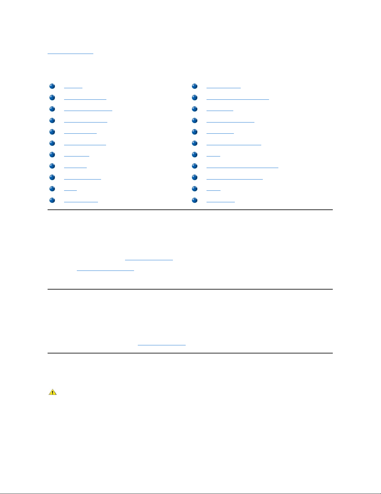
Desktop Chassis — Removing and Replacing Parts
Mini Tower Chassis — Removing and Replacing Parts
NOTE: You can obtain the latest version of this document from the Support section of the Dell Web site at http://www.dell.com.
Notes, Notices, and Cautions
Throughout this guide, blocks of text may be accompanied by an icon and printed in bold type or in italic type. These blocks are notes, notices,
and cautions, and they are used as follows:
Information in this document is subject to change without notice.
©1999 Dell Computer Corporation. All rights reserved.
Reproduction in any manner whatsoever without the written permission of Dell Computer Corporation is strictly forbidden.
Trademarks used in this text: Dell, Dell Precision, and the DELL logo are trademarks of Dell Computer Corporation.
Other trademarks and trade names may be used in this document to refer to either the entities claiming the marks and names or their products.
Dell Computer Corporation disclaims any proprietary interest in trademarks and trade names other than its own.
Initial release: 30 Nov 1999
NOTE: A NOTE indicates important information that helps you make better use of your system.
NOTICE: A NOTICE indicates either potential damage to hardware or loss of data and tells you how to avoid the problem.
CAUTION: A CAUTION indicates a potentially hazardous situation which, if not avoided, may result in minor or moderate
injury.
Page 2
Back to Contents Page
Desktop Chassis — RemovingandReplacingParts:DellPrecision™WorkStation420
Systems Service Manual
Overview
This section provides procedures for removing and replacing the components, assemblies, and subassemblies in the Dell Precision WorkStation
420 desktop chassis system.
Unless otherwise noted, each procedure assumes that the following conditions exist:
l You have performed the steps in "Precautionary Measures."
l You have removed the computer cover.
l You can replace or reinstall a part by performing the removal procedure in reverse order unless additional information is provided.
Recommended Tools
Most of the procedures in this file require the use of one or more of the following tools:
l #2 Phillips-head screwdriver
l A wrist grounding strap as explained in "Precautionary Measures."
Precautionary Measures
Before you perform any procedure in this section, take a few moments to read the following caution for your personal safety and to prevent
damage to the system from electrostatic discharge (ESD).
Overview
Control Panel
Recommended Tools
Chassis Intrusion Switch
Precautionary Measures
Drives
Restarting the System
Power Supply
Computer Cover
System Board Components
Interior Service Label
RIMMs
Internal View
Microprocessor/Heat Sink Assembly
Front-Panel Inserts
Cooling Fan
Expansion Cards
Battery
Expansion-Card Guide
System Board
CAUTION: FOR YOUR PERSONAL SAFETY AND PROTECTION OF THE EQUIPMENT
Before you start to work on the system, perform the following steps in the sequence listed:
1. Turn off the computer and all peripherals.
2. Disconnect the computer and peripherals from their AC power sources. Also, disconnect any telephone or telecommunication lines
from the computer. Doing so reduces the potential for personal injury or shock.
3. If you are disconnecting a peripheral from the computer or are removing a component from the system board, wait 10 to 20 seconds
after disconnecting the computer from AC power before disconnecting the peripheral or removing the component to avoid possible
damage to the system board.
4. Wear a wrist grounding strap, and clip it to an unpainted metal surface, such as the padlock loop on the back of the chassis. If a wrist
grounding strap is not available, touch any unpainted metal surface on the back of the computer or on the computer chassis, such as
Page 3
Restarting the System
To restart the system and reset the chassis intrusion detector, perform the following steps:
1. Replace the computer cover and reconnect the computer and peripherals to their power sources and turn them on.
ALERT! Cover was previously removed.
2. To reset the chassis intrusion detector, enter System Setup, select System Security,andresetChassis Intrusion to Enabled or
Enabled-Silent.
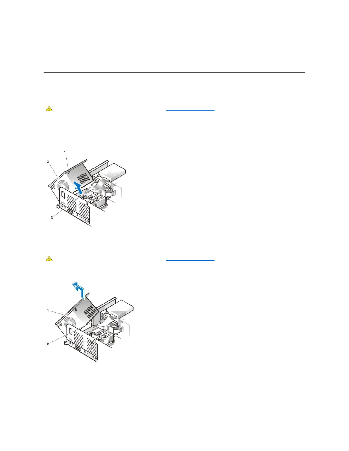
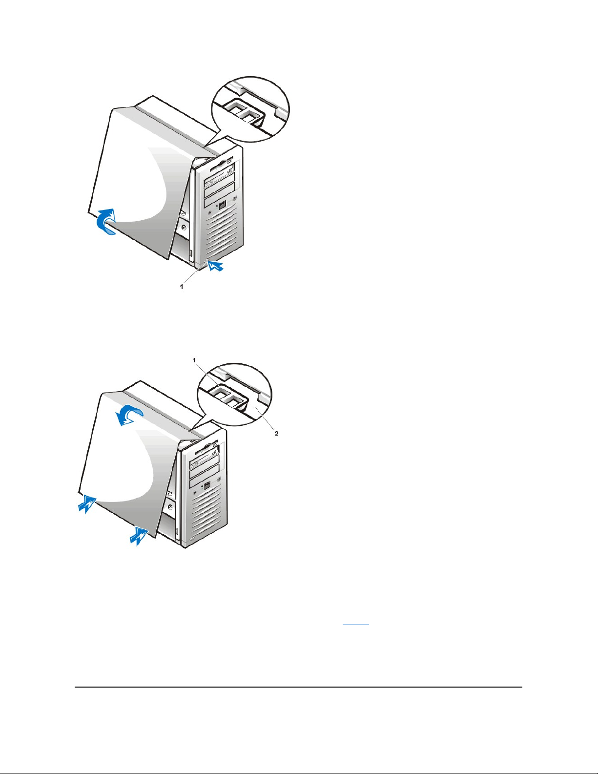
Computer Cover
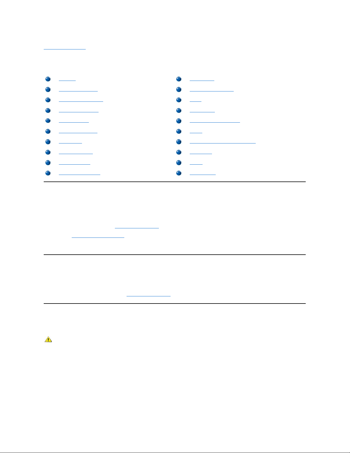
Figure 1. Computer Cover Removal
To remove the desktop chassis computer cover, perform the following steps:
1. Turn off your computer and peripherals, and observe the Caution for Your Personal Safety and Protection of the Equipment described in
"Precautionary Measures."
2. If you have installed a padlock through the padlock ring on the back panel, remove the padlock.
3. Press in on the two securing buttons until the cover is free to swing up (see Figure 1).
4. Raise the back of the cover, and pivot it toward the front of the computer.
5. Lift the cover off the hooks at the front of the chassis.
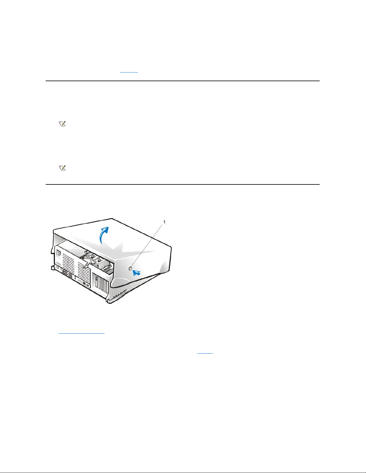
Figure 2. Computer Cover Replacement
thepowersupply,todischargeanystaticchargefromyourbodybeforetouchinganythinginsidethecomputer.Whileyouwork,
periodically touch an unpainted metal surface on the computer chassis to dissipate any static electricity that might harm internal
components. Also avoid touching components or contacts on a card and avoid touching pins on a chip.
5. Verify that the standby power light-emitting diode (LED) on the system board is not on. If it is on, you may need to wait 10 to 30
seconds for it to go out (see Figure 22 or the internal service label).
NOTE: When you start the system, the chassis intrusion detector will cause the following message to be displayed at the next
system start-up:
NOTE: If a setup password has been assigned by someone else, contact the network administrator for information on resetting the
chassis intrusion detector.
1
Securing buttons (2)
Page 4
To replace the computer cover, perform the following steps:
1. Check all cable connections, especially those that might have come loose during your work. Fold cables out of the way so that they do not
catch on the computer cover. Make sure cables are not routed over the drive bracket—they will prevent the cover from closing properly.
2. Check to see that no tools or extra parts (including screws) are left inside the computer's chassis.
3. Facing the left side of the computer, hold the cover at a slight angle as shown in Figure 2.
4. Fit the three cover hooks into the rectangular slots on the chassis. (It might be helpful to look down into the chassis to verify that the hooks are
in place.)
5. Pivot the cover down toward the back and into position. Make sure that the two securing buttons click into place.
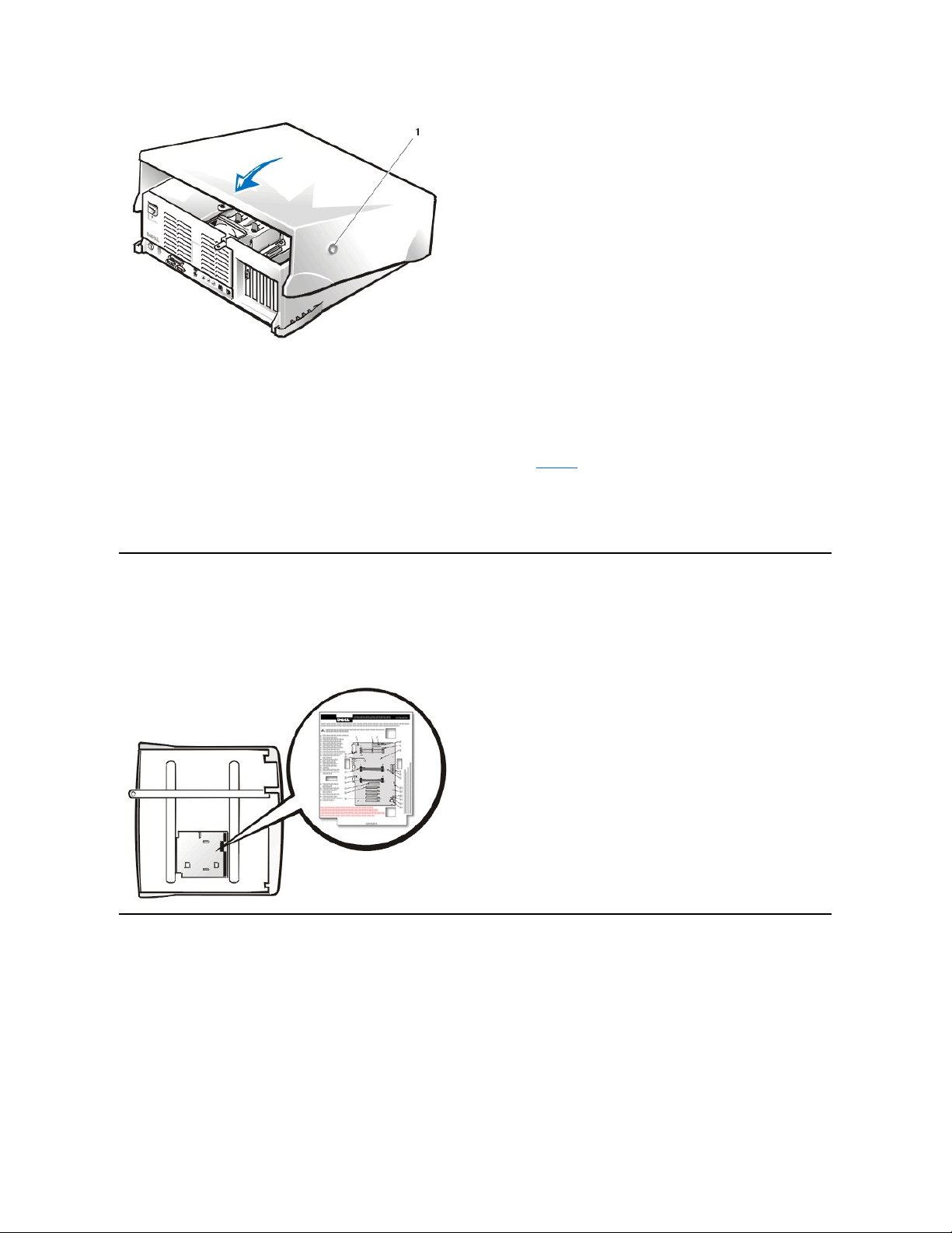
Interior Service Label
Figure 3 shows the location of the interior service label on the inside of the top cover. This label shows the location of components within the
chassis and locations of system board components and connectors. It also contains an important notice that provides instructions you need to
follow to help prevent damage to your system board while you troubleshoot and service the computer system.
Figure 3. Interior Service Label
Internal View
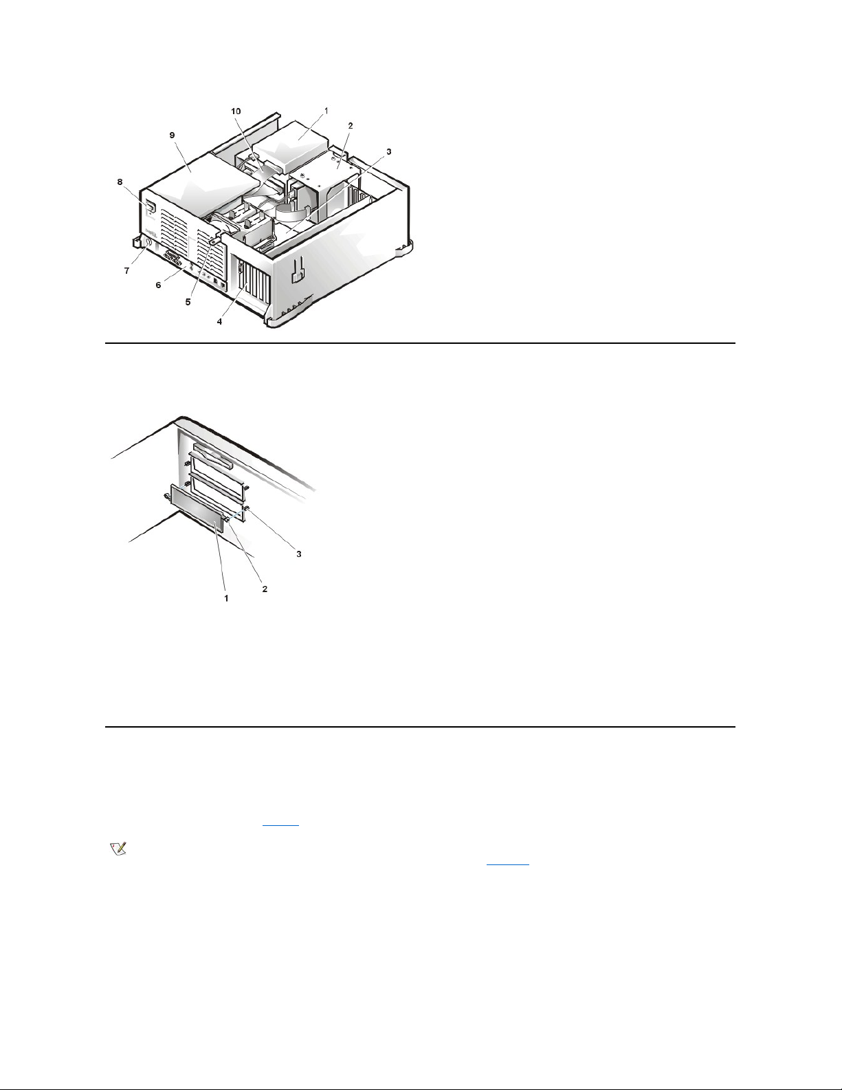
Figure 4 shows the chassis with the top cover removed.
Figure 4. Chassis Orientation View
1
Securing buttons (2)
Page 5
Front-Panel Inserts
Figure5.5.25-Inch Front-Panel Insert Removal
To remove a 5.25-inch front-panel insert, perform the following steps:
1. Hold the inverted top cover with the front facing you.
2. From the front of the top cover, use your thumbs to press inward on the insert until it snaps free of the cover.
To replace a 5.25-inch front-panel insert, position the two ring tabs over the posts on the inside of the bay opening, and then press the ring tabs
over the posts.
Expansion Cards
The Dell Precision 420 systems provide five 32-bit Peripheral Component Interconnect (PCI) expansion card slots. Slot 5 is shared with the RAID
port function.
The system contains five 32-bit expansion slots and a 32-bit AGP Pro 50 (4X) slot. If you use an AGP Pro 50 card, it occupies the AGP slot and
may occupy PCI slots 1 and 2. (See Figure6 for examples of these cards.)
Figure 6. Expansion Cards
1
Externally accessible drive bays
2
Hard-disk drive bracket
3
System board
4
Expansion card slots
5
Padlock ring
6
I/O panel connectors
7
Security cable slot
8
AC power receptacle
9
Power supply
10
Drive data cable
1
Front-panel insert
2
Ring tabs (2)
3
Posts (2)
NOTE: Before disconnecting a peripheral from the system or removing a component from the system board, verify that the standby
power LED on the system board has turned off. For the location of this LED, see Figure 22.
Page 6
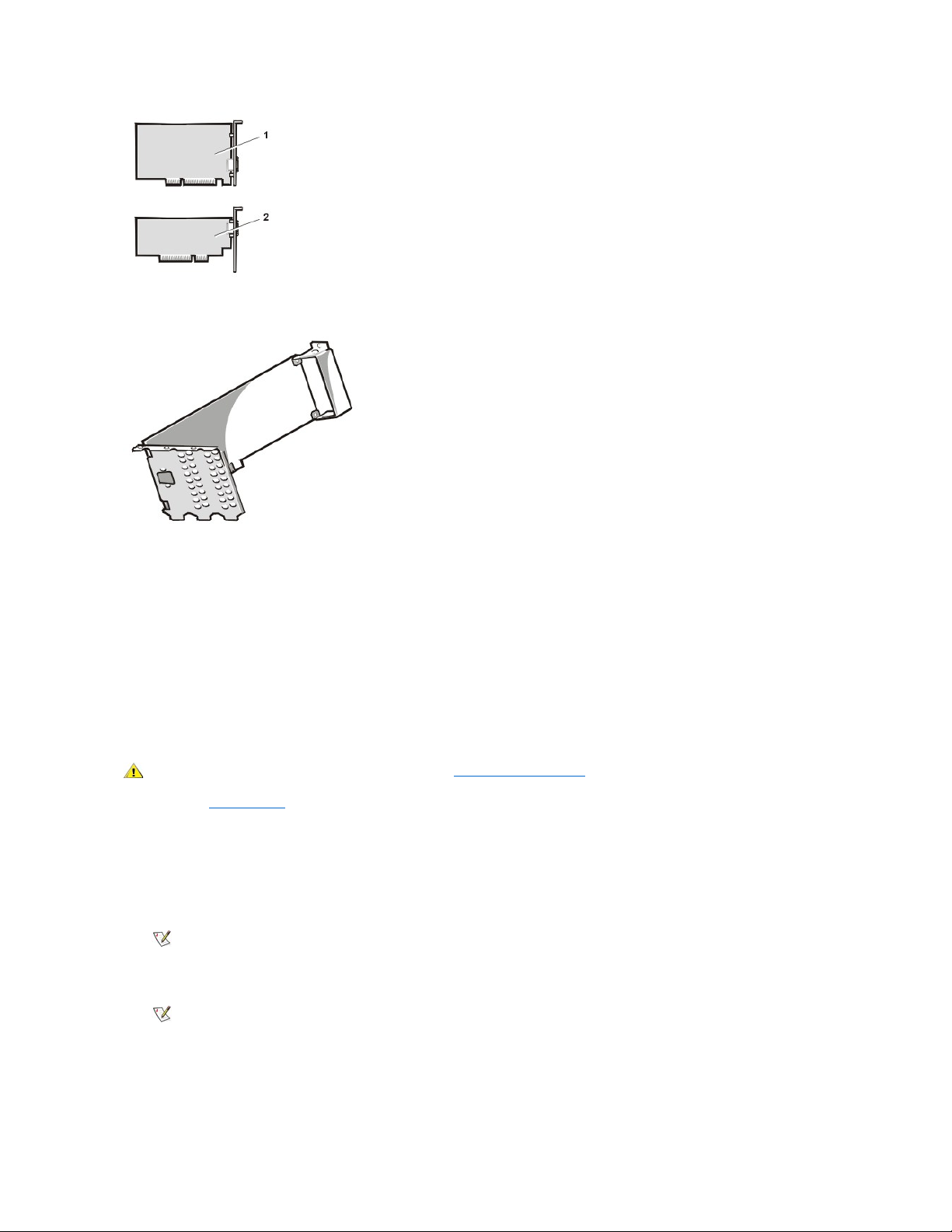
Figure 7. AGP Pro50 Card Extension
Figure 7 shows the card extension that may occupy PCI slots 1 and 2.
The following is a list of valid expansion-card combinations:
l One AGP card and five PCI cards
l One AGP card, four PCI cards, and one RAID card
l One AGP Pro50 card and four PCI cards
l One AGP Pro50 card, three PCI cards, and one RAID card
Expansion Card Removal
To remove an expansion card, perform the following steps.
1. Remove the computer cover.
2. Disconnect any cables connected to the card.
3. Unscrew the mounting bracket of the card you want to remove.
4. Grasp the card by its outside corners, and ease it out of its connector.
5. If you are removing the card permanently, install a metal filler bracket over the empty card-slot opening.
6. Replace the computer cover, and reconnect your computer and peripherals to their power sources and turn them on.
ALERT! Cover was previously removed.
7. To reset the chassis intrusion detector, enter System Setup, select System Security, and reset Chassis Intrusion to Enabled or
Enabled-Silent.
1
32-bit PCI expansion card
2
32-bit AGP card
CAUTION: Before you remove the computer cover, see "Precautionary Measures."
NOTE: Installing filler brackets over empty card-slot openings is necessary to maintain Federal Communications Commission
(FCC) certification of the system. The brackets also keep dust and dirt out of your computer.
NOTE: After you remove and replace the cover, the chassis intrusion detector will cause the following message to be displayed at
the next system start-up:
Page 7
Expansion-Card Guide
Figure 8. Expansion-Card Guide Removal
To remove the expansion-card guide, perform the following steps:
1. Remove the hard-disk drive bracket.
2. Face the computer from the front.
From the outside of the chassis, press in with your fingers on the two tabs on the left side of the expansion-card guide (see Figure8). This
will release the left tabs of the card guide from the chassis.
3. Rotate the released side of the card guide away from the chassis.
The left side of the card guide will swing away from the chassis. With the left side of the card guide away from the chassis, you can then pull
the card guide back and out of the chassis, which releases the two right tabs.
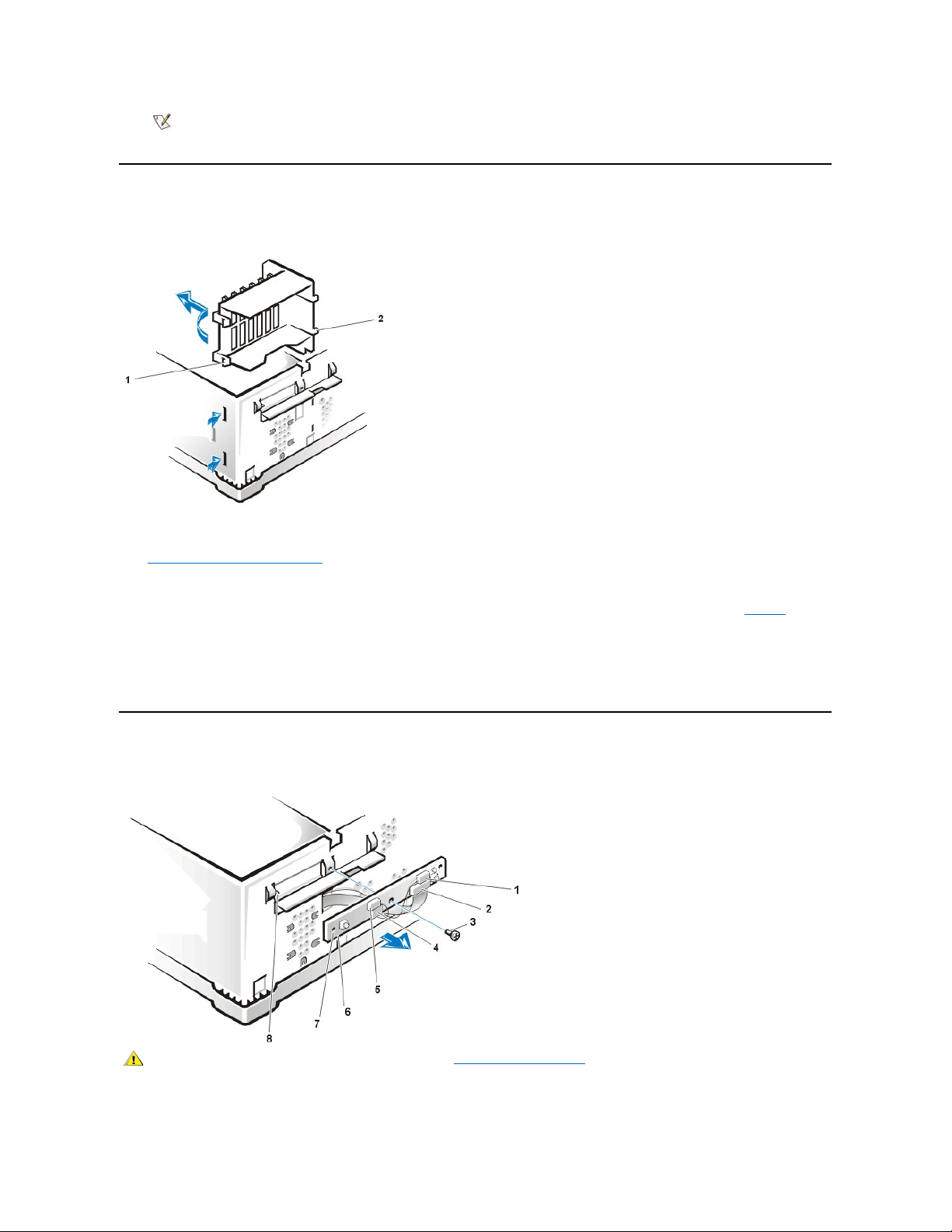
Control Panel
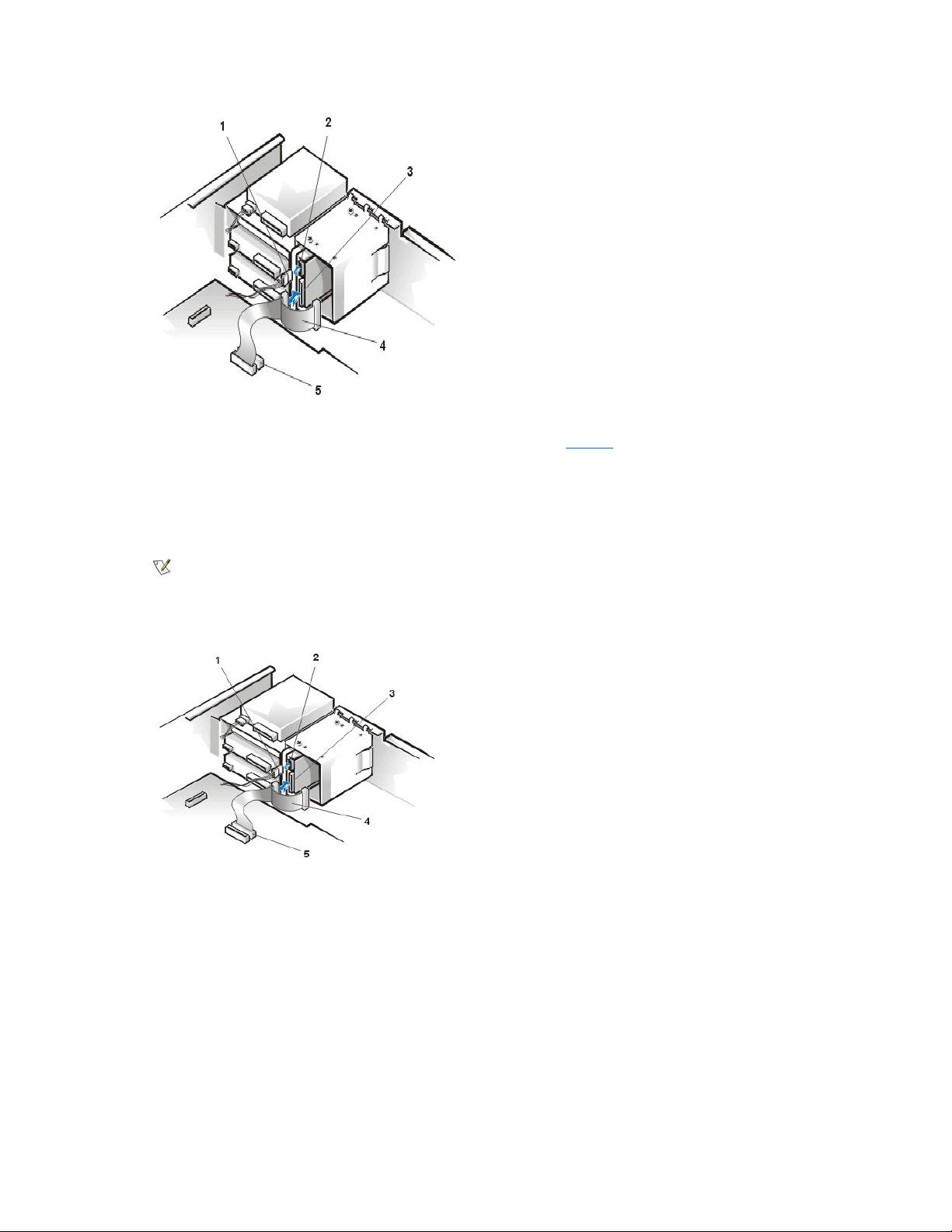
Figure 9. Control Panel Removal
To remove the control panel, perform the following steps:
NOTE: If a setup password has been assigned by someone else, contact your network administrator for information on resetting
the chassis intrusion detector.
1
Left tabs (2)
2
Right tabs (2)
1
Thermal sensor cable
2
Control panel cable
3
Screw
4
Speaker cable
5
Chassis intrusion switch
cable
6
Control panel
7
Alignment hole
8
Guide pin
CAUTION: Before you remove the computer cover, see "Precautionary Measures"
Page 8
1. Disconnect the control panel cable from the PANEL connector on the system board (see Figure 22 for the location of the PANEL connector).
2. Remove the mounting screw that secures the control panel to the chassis.
3. Disconnect the chassis intrusion switch cable connector from the control panel.
4. Disconnect the thermal sensor cable connector from the control panel.
5. Disconnect the speaker cable connector from the control panel.
6. Remove the control panel and cable from the chassis.
To reinstall the control panel, perform the removal procedure in reverse.
When you reinstall the control panel, be sure to align the control panel alignment hole and the guide pin located on the left side of the chassis front.
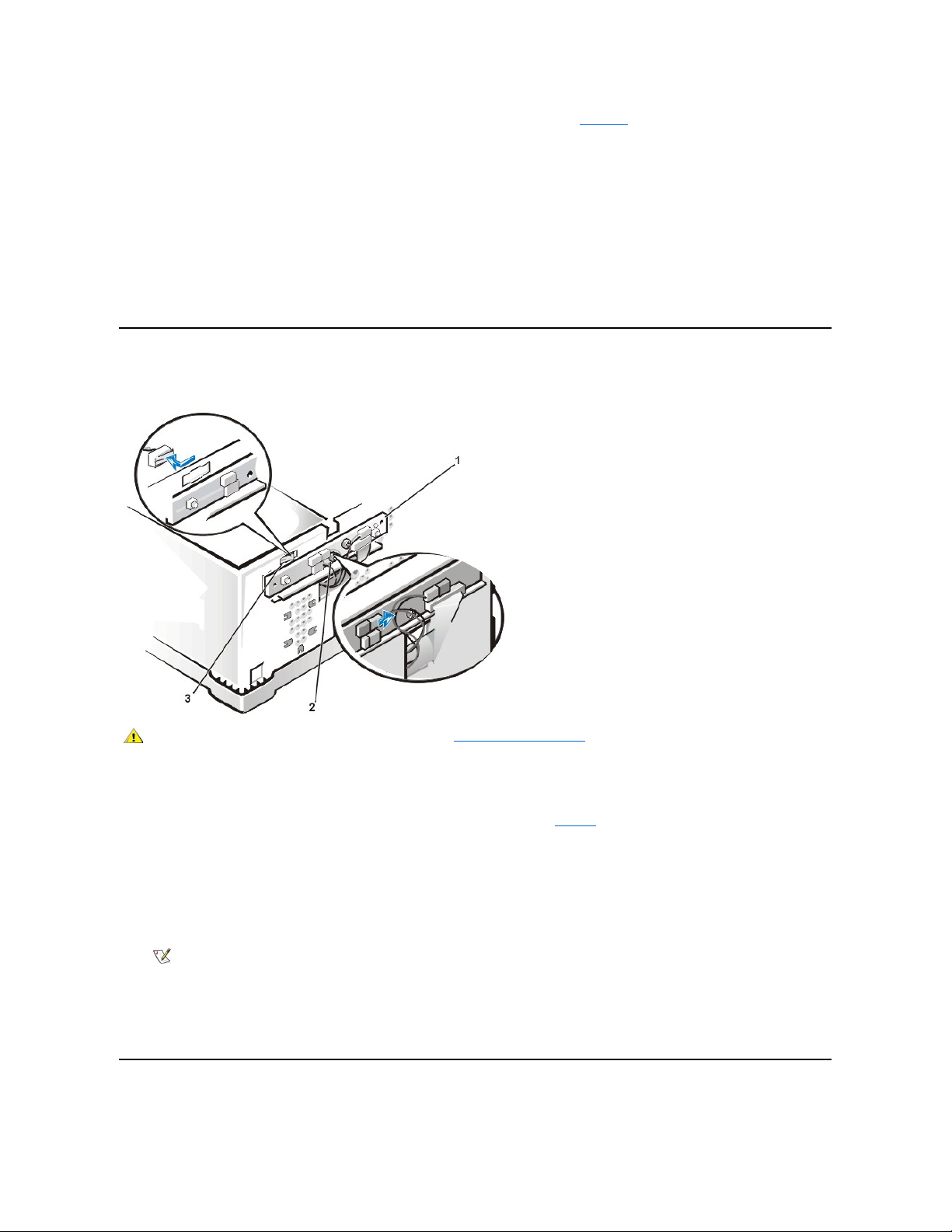
Chassis Intrusion Switch
Figure 10. Chassis Intrusion Switch Removal
To remove the chassis intrusion switch, perform the following steps:
1. From inside the chassis, slide the chassis intrusion switch to the side to release it from the chassis.
2. Disconnect the chassis intrusion switch cable connector from the control panel (see Figure9).
3. Remove the chassis intrusion switch and cable from the chassis.
Note the routing of the chassis intrusion cable to ensure the replacement is routed in the same manner.
4. Install the replacement chassis intrusion switch.
5. Replace the computer cover. Then reconnect your computer and peripherals to their power sources, and turn them on.
6. To reset the chassis intrusion detector, enter System Setup, select System Security,andresetChassis Intrusion to Enabled or
Enabled-Silent.
Drives
1
Control panel
2
Screw
3
Chassis intrusion switch
CAUTION: Before you remove the computer cover, see "Precautionary Measures"
NOTE: After you remove and replace the cover, the chassis intrusion detector will cause the following message to be
displayed at the next system start-up:
ALERT! Cover was previously removed.
Page 9
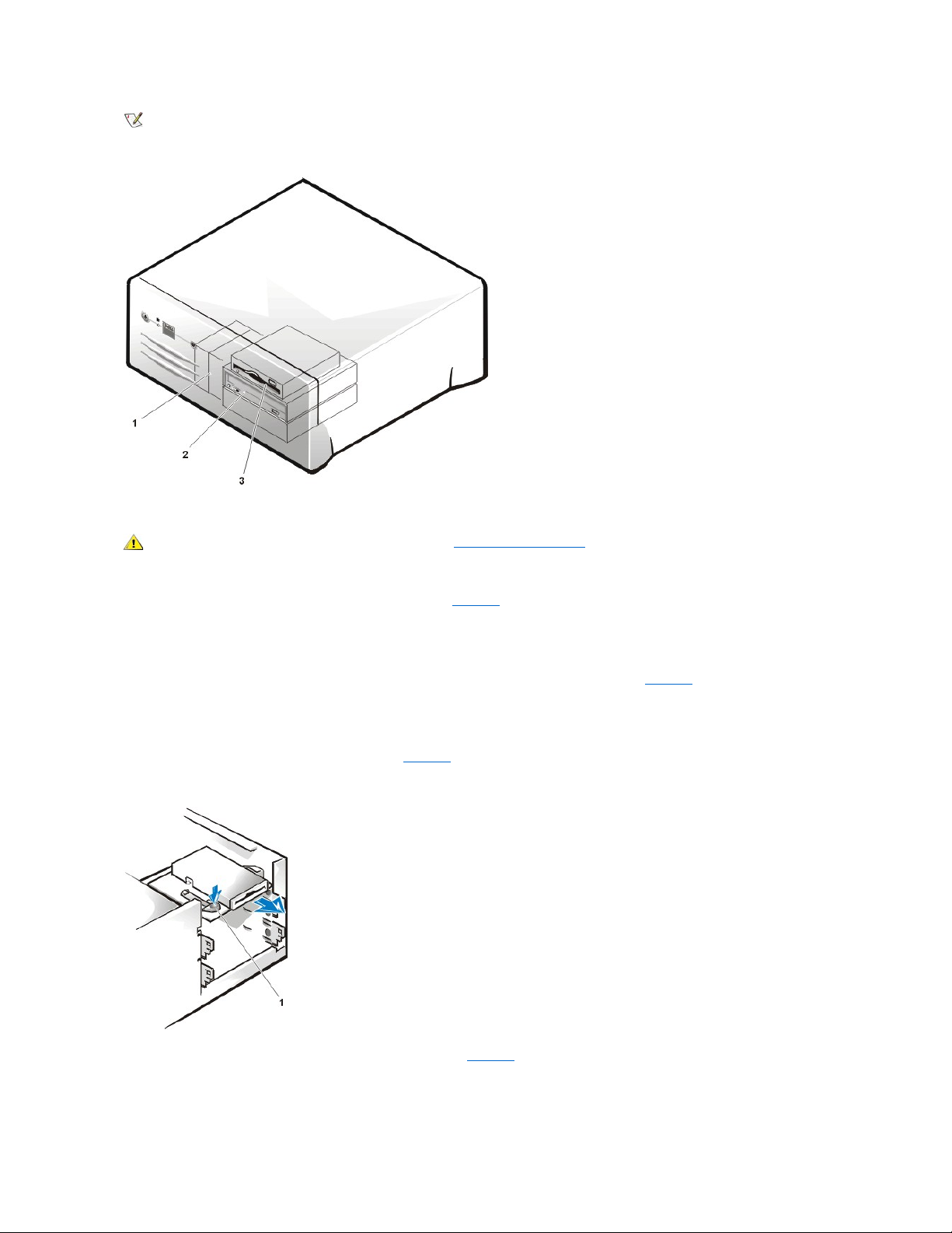
Figure 11. Drive Locations
Diskette Drive Removal
To remove the 3.5-inch diskette drive assembly, perform the following steps:
1. Rotate the system power supply up and out of the system (see Figure 20).
2. Disconnect the DC power cable from the back of the diskette drive.
3. Disconnect the interface ribbon cable from the back of the diskette drive.
The other end of this ribbon cable is connected to the DISKETTE connector on the system board (see Figure 22 for the location of the
DISKETTE connector).
Note the routing of the DC power and interface ribbon cables through the chassis as you disconnect them. It is important to route the cables
properly when you replace them to prevent them from being pinched or crimped.
4. Press down on the retaining-tab release button (see Figure 12) and pull the drive assembly forward to remove it from the chassis.
Figure 12. Diskette Drive Removal
5. Remove the screw securing the diskette drive to the bracket (see Figure 13).
Figure 13. 3.5-Inch Drive Bracket
NOTE: In all of the following procedures, left and right refer to your left and right as you face the front of the computer.
1
Hard-disk drives
2
5.25-inchdrives
(CD-ROM drive
shown)
3
3.5-inch diskette
drive
CAUTION: Before you remove the computer cover, see "Precautionary Measures"
1
Retaining-tab release button
Page 10
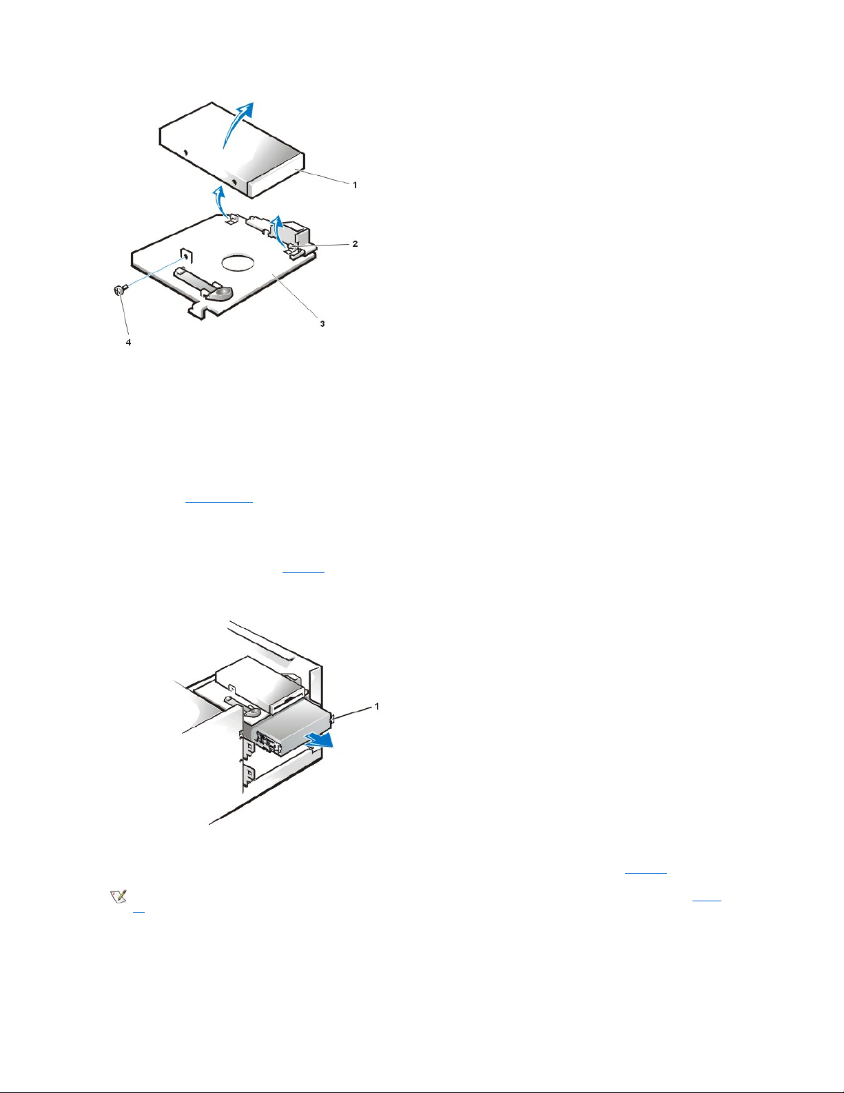
6. Rotate the left side of the diskette drive up until the drive is clear of the retaining tabs.
When you replace the 3.5-inch diskette drive on the bracket, be sure that the two retaining tabs on the right side of the bracket engage the
mounting holes in the side of the 3.5-inch diskette drive. Then replace the screw that holds the diskette drive to the bracket. To replace the 3.5-inch
diskette drive/bracket assembly in the chassis, slide the bracket tabs into the guides on the chassis until the bracket snaps into place. Reconnect
the DC power and interface cables.
5.25-Inch Diskette, LS-120 SuperDisk, Tape, or CD-ROM Drive Removal
To remove a diskette, LS-120 SuperDisk, tape, or CD-ROM drive, perform the following steps:
1. Remove the computer cover.
2. Disconnect the DC power cable and data cable from the back of the drive.
3. Squeeze the metal tabs that extend from each side of the drive bracket toward each other.
4. Pull the bracket out of the bay (see Figure 14).
Figure 14. 5.25-Inch Drive Removal
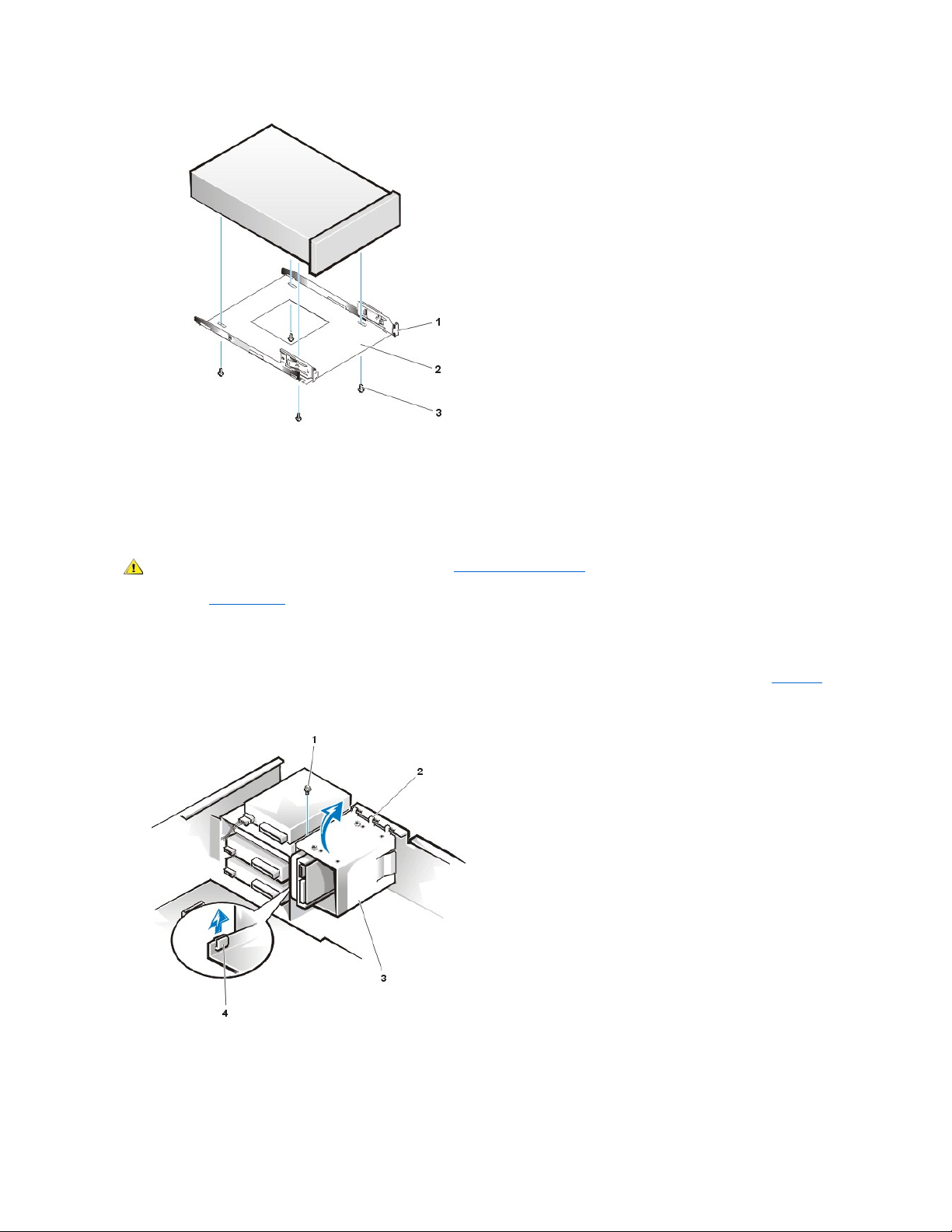
5. Turn the drive/bracket assembly upside down and remove the four screws that secure the drive to the bracket (see Figure 15).
Figure 15. 5.25-Inch Drive Bracket
1
3.5-inch diskette drive
2
Retaining tabs (2)
3
Bracket
4
Screw 1
Bracket tabs (2)
NOTE: For easier access inside the chassis, you may want to rotate the power supply out of the way temporarily. To do so, see Figure
20.
Page 11
Hard-Disk Drive Bracket Removal
To remove the hard-disk drive bracket, perform the following steps.
NOTICE: If you are removing a hard-disk drive that contains data you want to keep, be sure you have a backup of your files before
you begin this procedure.
1. Remove the computer cover.
2. Disconnect the DC power cable and data cable from the drive.
3. Remove the screw holding the drive bracket to the drive bay.
4. Rotate the drive bracket upward to disengage it from the latch on the drive bay, slide it to the left, and lift it out of the chassis (seeFigure16).
Figure 16. Hard-Disk Drive Bracket Removal
Hard-Disk Drive Removal
To remove a hard-disk drive from the drive bracket, perform the following steps.
1
Metal tab
2
Drive bracket
3
Screws (4)
CAUTION: Before you remove the computer cover, see "Precautionary Measures."
1
Screw
2
Hooks (3)
3
Drive bracket
4
Latch on drive bay
Page 12
1. Remove the four screws that secure the hard-disk drive to the drive bracket.
Retain these screws; they will be needed for the replacement drive.
2. Remove the hard-disk drive.
Hard-Disk Drive Replacement
To install a replacement hard-disk drive, perform the following steps.
1. If you are replacing a hard-disk drive that contains data you want to keep, be sure you have a backup of your files before you begin this
procedure.
2. Prepare the replacement drive for installation.
NOTICE: Wear a wrist grounding strap or ground yourself by touching an unpainted metal surface on the back of the
computer.
NOTICE: When you unpack the drive, do not set it on a hard surface, which may damage the drive. Instead, set the drive
on a surface such as a foam pad that will sufficiently cushion it.
Check the documentation for the drive to verify that it is configured for your computer system.
3. Remove the computer cover as instructed in "Computer Cover."
4. Remove the drive bracket from the chassis as instructed in "Hard-Disk Drive Bracket Removal."
5. Slide the drive into the chosen bay of the bracket, oriented so that the connectors on the back of the drive will face the back of the chassis
when the bracket is reinstalled (see Figure16).
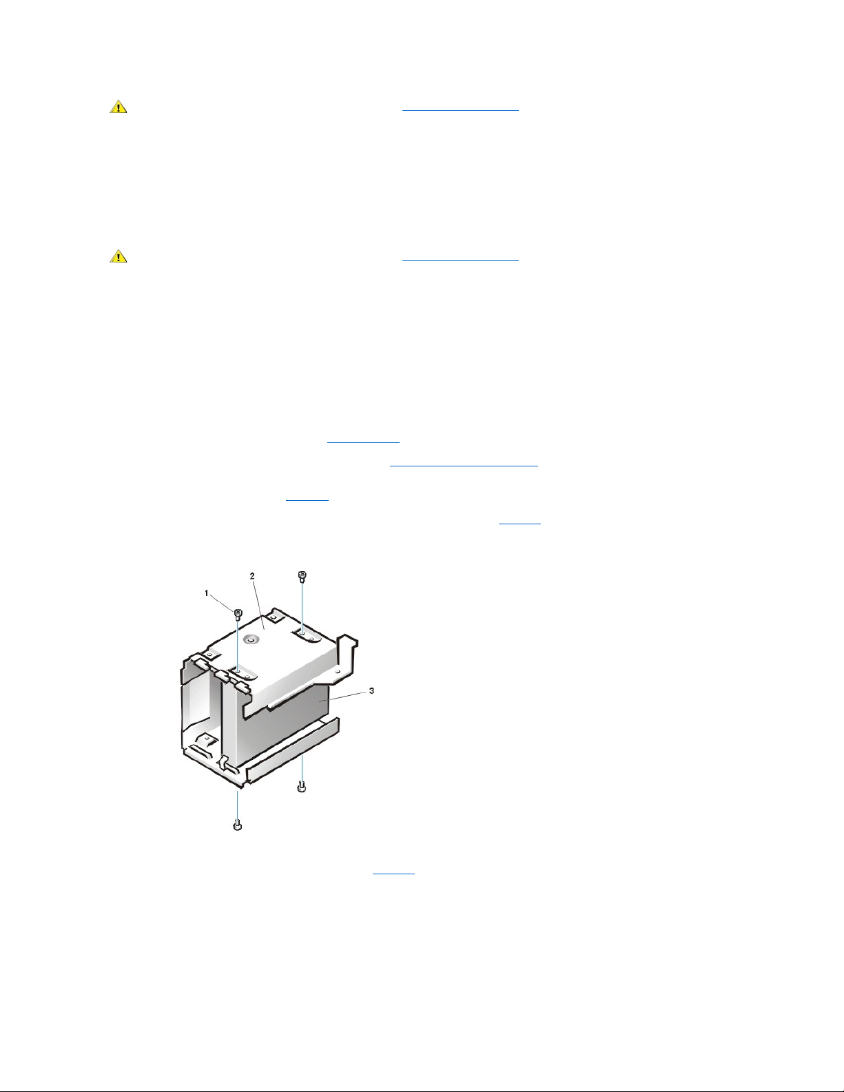
6. Align the four screw holes of the drive and bracket. Insert and tighten the screws (see Figure17).
Figure 17. Installing a Hard-Disk Drive in the Bracket
7. Reinstall the hard-disk drive bracket in the chassis (see Figure18).
Install the bracket into the chassis by inserting the hooks in the slots on the front of the chassis. Then lower the bracket to the bottom of the
chassis, making sure that the latch on the drive bay is engaged. Replace the screw holding the drive bracket to the drive bay.
Figure 18. Installing the Drive Bracket in the Chassis
CAUTION: Before you remove the computer cover, see "Precautionary Measures."
CAUTION: Before you remove the computer cover, see "Precautionary Measures."
1
Screws (4)
2
Drive bracket
3
Drive
Page 13
8. Connect a DC power cable to the power input connector on the back of the drive (see Figure19).
Check all connectors to be certain that they are properly cabled and firmly seated.
9. Connect one of the device connectors on the EIDE cable to the 40-pin interface connector on the back of the hard-disk drive.
NOTICE: You must match the colored strip on the EIDE cable with pin 1 on the drive's interface connector to avoid
possible damage to your system.
Figure 19. Attaching Hard-Disk Drive Cables
10. If it is not already connected, connect the other end of the EIDE cable to the IDE1 connector on the system board.
NOTICE: You must match the colored strip on the EIDE cable with pin 1 on the IDE1 connector to avoid possible damage to
your system.
11. Replace the computer cover. Then reconnect your computer and peripherals to their power sources, and turn them on.
12. If the drive you just installed is the primary drive, insert a bootable diskette into drive A.
13. Enter System Setup, and update Primary Drive 0 or Primary Drive 1.
After you update the System Setup settings, reboot the system.
14. Partition and logically format your drive before proceeding to the next step.
See the documentation for your operating system for instructions.
1
Screw
2
Hooks (3)
3
Drive bracket
4
Latch
NOTE: Ultra ATA/66 hard-disk drives require an 80-conductor cable to transfer data at full speed. The 80-conductor cable
has a 40-pin connector just like the Ultra ATA/33 cable but has twice as many wires within the cable itself. If you use an Ultra
ATA/33 cable with Ultra ATA/66 hard-disk drives, the drives will transfer data at Ultra ATA/33 speeds.
1
DC power cable
2
Power input connector on drive
3
Interface connector on drive
4
EIDE cable
5
IDE1 connector
Page 14
15. Test the hard-disk drive by running the Dell Diagnostics (see the online System User's Guide for more information).
16. If the drive you just installed is the primary drive, install your operating system on the hard-disk drive.
Refer to the documentation that came with your operating system.
Power Supply
To access some components on the system board, you may have to rotate the system power supply out of the way. To rotate the power supply,
perform the following steps.
1. Remove the computer cover as instructed in "Computer Cover."
2. Disconnect the AC power cable from the AC power receptacle on the back of the power supply (see Figure 20).
Figure 20. Rotating the Power Supply
3. Free the power supply by pressing the securing tab labeled "RELEASE" and rotate it upward to a vertical position. See Figure20.
To remove the power supply, perform the following steps.
Figure 21. Removing the Power Supply
1. Remove the computer cover as instructed in "Computer Cover."
2. Disconnect the AC power cable from the AC power receptacle on the back of the power supply.
3. Disconnect the DC power cables that attach to the diskette drive, any installed 5.25-inch drives, and hard-disk drives mounted in the
internally-accessible drive bracket.
CAUTION: Before you remove the computer cover, see "Precautionary Measures."
1
Securing tab
2
Power supply
3
Release latch
CAUTION: Before you remove the computer cover, see "Precautionary Measures"
1
Power supply
2
Slot
Page 15
4. Rotate the power supply up and out of the way of the system board (see Figure 20).
5. Disconnect the power supply connectors from the POWER_1 and POWER_2 connectors on the system board.
6. Carefully fold the DC power supply cables you have disconnected and place them outside the chassis.
7. With the power supply in its rotated position up and away from the system board and chassis, lift up on the front end of the power supply, and
then move that end of the power supply out, away from the chassis (see Figure 21).
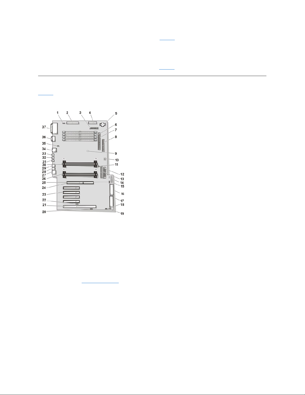
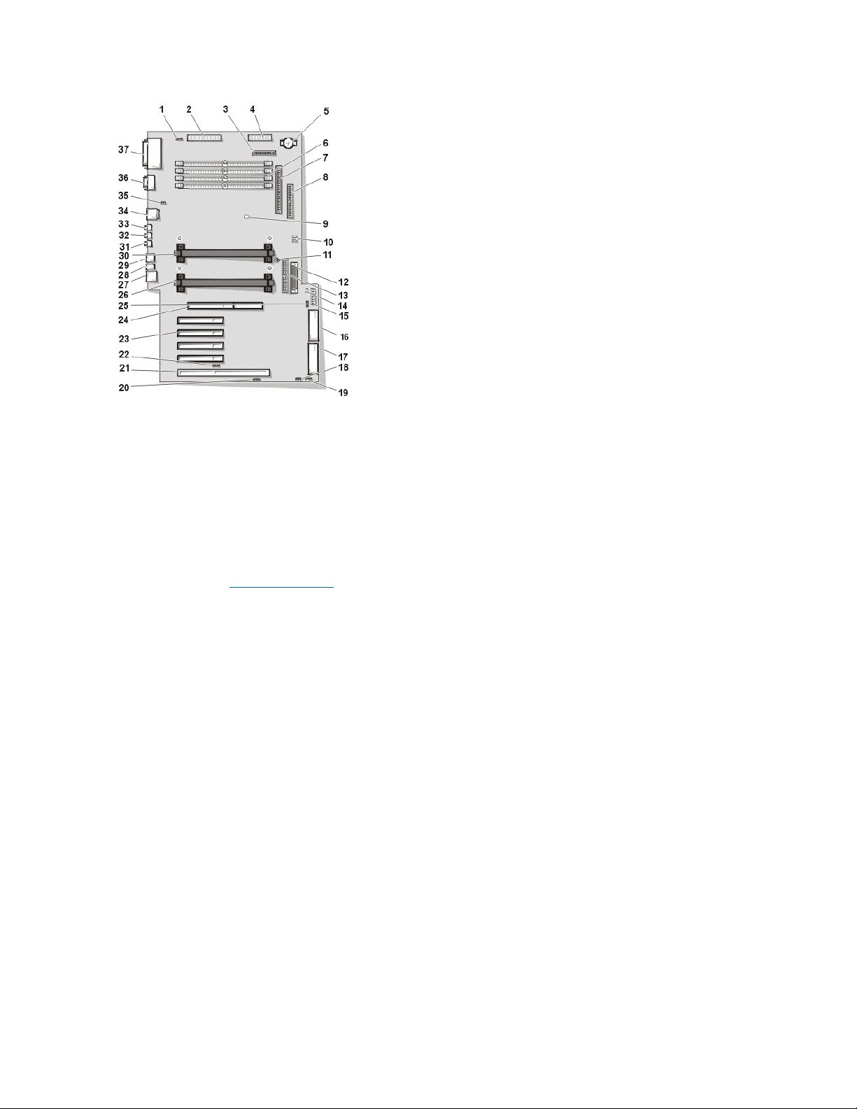
System Board Components
Figure 22 shows the system board and the location of all its sockets and connectors.
Figure 22. System Board Components
1
CD-ROM drive audio connector
2
Main power 1 connector (desktop chassis)
3
Diskette connector
4
Main power 2 connector (desktop chassis)
5
Battery
6
RIMM (memory) sockets
7
SCSI narrow connector
8
Secondary EIDE connector
9
Suspend-To-RAM LED
10
Jumper block (see "System Board Jumpers")
11
System board screw
12
LVD SCSI connector
13
Primary EIDE connector
14
Standby power LED
15
Control panel connector
16
MT power 2 connector (mini tower chassis)
17
MT power 1 connector (mini tower chassis)
18
Modem (TAPI) connector
19
Card-cage fan power connector
20
Auxiliary sound input connector
21
PCI/RAID expansion card connector
Page 16

System Board Jumpers
Figure 23 shows the location of the jumpers on the system board. Table1 lists the system board jumpers and their settings.
Figure 23. System Board Jumpers
Jumpers are small blocks on a circuit board with two or more pins emerging from them. Plastic plugs containing a wire fit down over the pins. The
wire connects the pins and creates a circuit.
NOTICE: Make sure your system is turned off before you change a jumper setting. Otherwise, damage to your system or
unpredictable results may occur.
To change a jumper setting, pull the plug off its pin(s) and carefully fit it down onto the pin(s) indicated.
Table 1. System Board Jumper Settings
22
Auxiliary hard-disk drive access LED connector
23
PCI expansion slots
24
AGP graphics slot
25
Remote wakeup on LAN connector
26
Primary processor 0 socket
27
Network cable connector
28
Diagnostic LEDs
29
USB connectors
30
Secondary processor 1 socket
31
Line-in connector
32
Line-out connector
33
Microphone Connector
34
Mouse/keyboard (stacked)
35
System fan power connector
36
Serial port 1/ serial port 2 (stacked)
37
Parallel port/external SCSI port (stacked)
Jumper
Setting
Description
PSWD
(default)
Password features are enabled.
Password features are disabled.
RTCRST
Real-time clock reset. Can be used for troubleshooting purposes.
jumpered unjumpered
Page 17

System Board Labels
Table 2 lists the labels for connectors and sockets on your system board, and it gives a brief description of their functions.
Table 2. System Board Connector and Socket Labels
RIMMs
Connector or Socket Label
Description
AGP
AGP graphics card slot
AUX_LED
Hard-disk drive LED connector
Battery
Battery socket
CD_IN
CD-ROM audio interface connector
DISKETTE
Diskette/tape drive interface connector
ENET
Integrated NIC connector
EXT_SPKR
External speaker connector
FAN_CCAG
Card cage area fan power connector
FAN_SYS
Microprocessor fan power connector
HD_LED
Hard-disk drive
IDEn
EIDE interface connector
KEYB
Keyboard connector
LINE_OUT
External speaker connector
LINE_IN
Audio input connector
MIC
Microphone connector
MONITOR
Video connector
MOUSE
Mouse connector
MPWR1
Main power 1 connector (desktop)
MPWR2
Main power 2 connector (desktop)
MTPWR1
Main power 1 connector (mini tower)
MTPWR2
Main power 2 connector (mini tower)
PANEL
Control panel connector
PARALLEL
Parallel port connector; sometimes referred to as LPT1
PCIn
PCI expansion-card connector
POWER_1
Main power input connector
POWER_2
3.3-V power input connector
PROC_0
Primary microprocessor connector
PROC_1
Secondary microprocessor connector
RIMM_x
RIMM socket
SCSI
External SCSl port connector
SCSI_LVD
Internal LVD SCSl connector
SCSI_NARROW
Internal SCSl Narrow connector
SERIAL1/2
Serial port connectors
STANDBY_LED
Standby power LED
STR_LED
Suspend-to-RAM LED
USB
USB connectors
TAPI
Modem connector
WOL
Remote Wakeup on LAN power connector
Page 18

To remove a Rambus in-line memory module (RIMM), perform the following steps.
1. Remove the computer cover.
2. PressthesecuringclipsoutwardsimultaneouslyuntiltheRIMMdisengagesandpopsoutslightlyfromthesocket(seeFigure24).
Figure 24. RIMM Removal
To install replacement memory, perform the following steps.
1. Remove the computer cover.
2. If necessary, remove any RIMMs that occupy sockets in which you plan to install the replacement RIMMs.
3. Install the RIMMs:
a. Locate the plastic securing clips at each end of the socket (see Figure 25).
b. Press the clips outward until they snap open.
c. Press the RIMM straight into the slot running down the center of the socket until the securing tabs snap into place around the ends
of the RIMM.
Figure 25. RIMM Installation
4. Replace the computer cover, and reconnect your computer and peripherals to their electrical outlets and turn them on.
CAUTION: Before you remove the computer cover, see "Precautionary Measures"
CAUTION: To avoid the possibility of electric shock, turn off the computer and any peripherals, disconnect them from their
electrical outlets, and then wait at least 5 seconds before you remove the computer cover.
CAUTION: The RIMMs can get extremely hot during system operation. To avoid dangerous burns, be sure that the RIMMs
have had sufficient time to cool before you touch them.
1
Securing clips (2)
CAUTION: To avoid the possibility of electric shock, turn off the computer and any peripherals, disconnect them from their
electrical outlets, and then wait at least 5 seconds before you remove the computer cover. Also, before you replace memory,
see the other precautions in "Precautionary Measures. "
NOTES: If you are not installing a replacement RIMM at this time, you MUST remove the remaining RIMM in the pair and install a pair
of continuity modules (CRIMM).
When operating with a single pair of RIMMs, they MUST occupy sockets RIMMB-1 and RIMMA-2, with CRIMMs installed in RIMMB-3
and RIMMA-4.
1
Securing clips (2)
2
Notches (2)
Page 19

The system detects that the new memory does not match the existing system configuration information and generates the following
message:
The amount of system memory has changed.
Strike the F1 key to continue, F2 to run the setup utility
5. Press <F2> to enter System Setup, and check the value for System Memory.
The system should have already changed the value of System Memory to reflect the newly installed memory. Verify the new total. If it is
correct, skip to step 7.
6. If the memory total is incorrect, turn off and disconnect your computer and peripherals from their electrical outlets. Remove the computer
cover, rotate the power supply, and check the installed RIMMs to make sure that they are seated properly in their sockets. Then repeat steps
3, 4, and 5.
7. Reset the chassis intrusion detector by entering System Setup, selecting System Security, and changing Chassis Intrusion to Enabled
or Enabled-Silent.
8. When the System Memory total is correct, press <Esc> to exit System Setup.
9. Run the Dell Diagnostics to verify that the RIMMs are operating properly.
Microprocessor/Heat Sink Assembly
To replace a microprocessor, perform the following steps.
1. Remove the computer cover according to the instructions in "Computer Cover."
2. Rotate the power supply as described in "Power Supply."
3. Remove the existing microprocessor from its connector.
a. Squeeze in on the two pairs of tabs on the airflow shroud and lift it away.
b. Unscrew and remove the two large thumbscrews that secure the heat sink to the system board.
c. Press outward on the guide bracket release latches.
d. Grasp the processor/heat sink assembly firmly, and pull it away from the guide bracket assembly assembly (see Figure 26).
You must use up to 15 pounds of force to disengage the processor from the connector.
Figure 26. Microprocessor Removal
NOTE: After you remove and replace the cover, the chassis intrusion detector causes the following message to appear on the
screen at the next system start-up:
ALERT! Cover was previously removed.
NOTE: If a setup password has been assigned by someone else, contact your network administrator for information on resetting
the chassis intrusion detector.
CAUTION: The microprocessors can get extremely hot during system operation. To avoid dangerous burns, be sure that the
microprocessors have had sufficient time to cool before you touch them.
CAUTION: To avoid the possibility of electric shock, turn off the computer and any peripherals, disconnect them from their
electrical outlets, and then wait at least 5 seconds before you remove the computer cover.
NOTE: Dell recommends that only a technically knowledgeable person perform this procedure.
CAUTION: Before you remove the computer cover, see "Precautionary Measures"
NOTE: Before disconnecting a peripheral from the system or removing a component from the system board, verify that the standby
power LED on the system board has turned off. For the location of this LED, see Figure 22.
Page 20

Figure 27. Microprocessor Replacement
To insert the new microprocessor/heat sink assembly into the system board connector, perform the following steps (this procedure assumes the
microprocessor removal procedure was just performed).
1. Press the processor firmly into its connector until it is fully seated.
You must use up to 25 lb of force to fully seat the processor in its connector.
2. Install the two large thumbscrews that secure the heat sink to the system board.
3. Replace the airflow shroud.
1
Airflow shroud
2
Thumbscrews (2)
3
Processor/heat sink assembly
4
Guide bracket
5
Second processor
1
Airflow shroud
2
Thumbscrews (2)
3
Processor/heat sink assembly
4
Guide bracket
5
Second processor
NOTE: Dell recommends that only a technically knowledgeable person perform this procedure.
CAUTION: Before you remove the computer cover, see "Precautionary Measures"
NOTE: Before disconnecting a peripheral from the system or removing a component from the system board, verify that the standby
power LED on the system board has turned off. For the location of this LED, see Figure 22.
Page 21

4. Rotate the power supply back into position, making sure that the securing tab snaps into place.
5. Replace the computer cover, and reconnect your computer and peripherals to their power sources and turn them on.
6. Enter System Setup and confirm that the top line in the System Data area correctly identifies the installed processor(s).
7. While in System Setup, select System Security, and reset Chassis Intrusion to Enabled or Enabled-Silent.
8. Run the Dell Diagnostics to verify that the new microprocessor is operating correctly.
Cooling Fan
Figure 28. Cooling Fan Removal
To remove the cooling fan, perform the following steps.
1. Remove the computer cover.
2. Rotate the power supply.
3. Squeeze in on the two pairs of tabs on the airflow shroud and lift it away.
4. Disconnect the fan power cable from the FAN_SYS connector (see Figure 22 for location).
5. Gently pull on the plastic locking tab, and slide the fan toward the power supply to disengage the four latching tabs holding the fan to the back
of the chassis (see Figure 28).
Battery
Figure 29. Battery Removal
NOTE: After you remove and replace the cover, the chassis intrusion detector will cause the following message to be
displayed at the next system start-up:
ALERT! Cover was previously removed.
NOTE: If a setup password has been assigned by someone else, contact your network administrator for information on resetting
the chassis intrusion detector.
1
Fan power cable
2
Fan3Plastic locking tab
CAUTION: Before you remove the computer cover, see "Precautionary Measures"
Page 22

To remove the system battery, perform the following steps:
1. If possible, enter System Setup and print the System Setup screens.
If the settings are lost while you are replacing the battery, you can refer to your written or printed cop of the system configuration information
to restore the correct settings.
2. To access the battery on the system board, rotate the power supply as described in "Rotating the Power Supply."
3. If installed, remove the CD-ROM drive according to the instructions in "Diskette, LS-120 SuperDisk, Tape, or CD-ROM Drive Removal" to
access the battery.
4. Locate the battery and remove it.
The battery is mounted in a socket labeled "BATTERY" at the upper front-right corner of the system board (as you face the side of the
system) (see Figure 22).
NOTICE: If you pry the battery out of its socket with a blunt object, be careful not to touch the system board with the object.
Make certain that the object is inserted between the battery and the socket before attempting to pry out the battery. Otherwise,
you may damage the system board by prying off the socket or by breaking circuit traces on the system board.
5. Remove the system battery by carefully prying it out of its socket with your fingers or with a blunt, nonconducting object such as a plastic
screwdriver.
When you replace the system battery, orient the new battery with the "+" facing up. Insert the battery into its socket and snap it into place.
System Board
Figure 30. System Board Removal
To remove the system board, perform the following steps.
1
Battery
2
Socket
NOTE: Before disconnecting a peripheral from the system or removing a component from the system board, verify that the standby
power LED on the system board has turned off. For the location of this LED, see Figure 22.
CAUTION: There is a danger of the new battery exploding if it is incorrectly installed. Replace the battery only with the same or
equivalent type recommended by the manufacturer. Discard used batteries according to the manufacturer’s instructions.
CAUTION: Before you remove the computer cover, see "Precautionary Measures"
1
System board
2
Screw
Page 23

1. Remove the computer cover.
2. Disconnect all cables from their connectors at the back of the computer.
3. Rotate the power supply.
4. Disconnect all cables from the system board.
5. Remove the RIMMs.
6. Remove the airflow shroud, the primary processor, and the secondary processor or terminator card.
7. Remove all expansion cards from the system.
8. Slide all externally accessible drives and brackets partially out of the chassis.
9. Remove the hard-disk drive bracket from the chassis.
10. Remove the microprocessor cooling fan.
11. Remove the screw that secures the system board to the bottom of the chassis (see Figure30).
12. Slide the system board toward the front of the chassis until it stops.
13. Carefully raise the front of the system board and lift the board out of the chassis at an angle.
To replace the system board, perform the following steps:
1. Carefully replace the system board in the chassis by performing steps 11 through 13 of the removal process in reverse.
2. Push down near each slot to engage the grounding clip onto its corresponding tab.
3. Push evenly on both sides of the system board as you slide and lock it into position (do not twist the system board).
4. Reinstall the mounting screw.
5. Reinstall all components on the system board by performing steps 4 through 10 of the removal process in reverse.
6. Set the jumpers on the new system board so that they are identical to those on the old board, unless you are installing a microprocessor
upgrade.
7. Replace the computer cover, connect all cables, and restart the system. Run System Setup to ensure that your settings are correct and that
all system board components are correctly reported.
8. Run the Dell Diagnostics.
Back to Contents Page
NOTE: Before disconnecting a peripheral from the system or removing a component from the system board, verify that the standby
power LED on the system board has turned off. For the location of this LED, see Figure22.
CAUTION: The microprocessors and RIMMs can get extremely hot during system operation. To avoid dangerous burns, be
sure that the microprocessors and RIMMs have had sufficient time to cool before you touch them.
Page 24
Back to Contents Page
Mini Tower Chassis — RemovingandReplacingParts:DellPrecision™WorkStation
420 Systems Service Manual
Overview
This section provides procedures for removing and replacing the components, assemblies, and subassemblies in the Dell Precision WorkStation
420 mini tower chassis system.
Unless otherwise noted, each procedure assumes that the following conditions exist:
l You have performed the steps in "Precautionary Measures."
l You have removed the computer cover.
l You can replace or reinstall a part by performing the removal procedure in reverse order unless additional information is provided.
Recommended Tools
Most of the procedures in this file require the use of one or more of the following tools:
l Wide flat-blade screwdriver
l #2 Phillips-head screwdriver
l A wrist grounding strap as explained in "Precautionary Measures."
Precautionary Measures
Before you perform any procedure in this section, take a few moments to read the following caution for your personal safety and to prevent
damage to the system from electrostatic discharge (ESD).
Overview
Expansion Cards
Recommended Tools
Expansion-Card Guide and Fan
Precautionary Measures
Control Panel
Restarting the System
Chassis Intrusion Switch
Computer Cover
Power Supply
Interior Service Label
System Board Components
Internal View
RIMMs
Front Panel
Microprocessor/Heat Sink Assembly
Front-Panel Inserts
Microprocessor Cooling Fan
Drives
Battery
AGP Card Brace
System Board
CAUTION: FOR YOUR PERSONAL SAFETY AND PROTECTION OF THE EQUIPMENT
Before you start to work on the system, perform the following steps in the sequence listed:
1. Turn off the computer and all peripherals.
2. Disconnect the computer and peripherals from their AC power sources. Also, disconnect any telephone or telecommunication lines
from the computer. Doing so reduces the potential for personal injury or shock.
3. If you are disconnecting a peripheral from the computer or are removing a component from the system board, wait 10 to 20 seconds
after disconnecting the computer from AC power before disconnecting the peripheral or removing the component to avoid possible
Page 25

Restarting the System
To restart the system and reset the chassis intrusion detector, perform the following steps:
1. Replace the computer cover and reconnect the computer and peripherals to their power sources and turn them on.
ALERT! Cover was previously removed.
2. To reset the chassis intrusion detector, enter System Setup, select System Security, and reset Chassis Intrusion to Enabled or
Enabled-Silent.
Computer Cover
Figure 1. Padlock Ring Release
To remove the mini tower chassis computer cover, perform the following steps:
1. Turn off your computer and peripherals, and observe the Caution for Your Personal Safety and Protection of the Equipment described in
"Precautionary Measures."
2. If you have installed a padlock through the padlock ring on the back panel, remove the padlock and, facing the back of the computer, slide the
padlock ring to the left to unlock the cover release mechanism (see Figure 1).
3. Face the left side cover and press the release button (located at the bottom-left corner of the front panel) (see Figure 2).
Figure 2. Computer Cover Removal
damage to the system board.
4. Wear a wrist grounding strap, and clip it to an unpainted metal surface, such as the padlock loop on the back of the chassis. If a wrist
grounding strap is not available, touch any unpainted metal surface on the back of the computer or on the computer chassis, such as
thepowersupply,todischargeanystaticchargefromyourbodybeforetouchinganythinginsidethecomputer.Whileyouwork,
periodically touch an unpainted metal surface on the computer chassis to dissipate any static electricity that might harm internal
components. Also avoid touching components or contacts on a card and avoid touching pins on a chip.
5. Verify that the standby power light-emitting diode (LED) on the system board is not on. If it is on, you may need to wait 10 to 30
seconds for it to go out (see Figure 28).
NOTE: When you start the system, the chassis intrusion detector will cause the following message to be displayed at the
next system start-up:
NOTE: If a setup password has been assigned by someone else, contact the network administrator for information on
resetting the chassis intrusion detector.
1
Security cable slot
2
Padlock ring
Page 26
4. Lift the bottom of the cover, allowing it to pivot up toward you.
5. Disengage the tabs that secure the cover to the top of the chassis, and lift the cover away.
Figure 3. Computer Cover Replacement
To replace the computer cover, perform the following steps:
1. Check all cable connections, especially those that might have come loose during your work. Fold cables out of the way so that they do not
catch on the computer cover. Make sure cables are not routed over the drive cage—they will prevent the cover from closing properly.
2. Check to see that no tools or extra parts (including screws) are left inside the computer chassis.
3. Face the left side of the computer and hold the cover at a slight angle as shown in Figure3.
4. Align the top of the cover with the top of the chassis and insert the three hooks on the cover into the three recessed slots on the computer
chassis so that the tabs catch the hooks inside the slots.
5. Pivot the cover down toward the bottom of the chassis and into position. Make sure that the securing hooks at the bottom of the cover click
into place.
1
Release button
1
Hook (3)
2
Recessed slot (3)
Page 27

Interior Service Label
Figure 4 shows the location of the interior service label on the inside of the system cover. This label shows the location of components within the
chassis and locations of system board components and connectors. It also contains an important notice that provides instructions you need to
follow to help prevent damage to your system board while you troubleshoot and service the computer system.
Figure 4. Interior Service Label
Internal View
Figure 5 shows the chassis with the cover removed to help you orient yourself when you work inside the computer.
Figure 5. Orientation View
Front Panel
To access some drive bays in the mini tower chassis, you must first remove the front panel. To remove the front panel, you first must remove the
computer cover (see "Computer Cover"). With the cover removed, release the panel by pressing the green tab release marked with the icon (see
Figure 6).
Figure 6. Front Panel Removal
1
Externally
accessible drive
bays
2
Hard-disk drive
cage
3
Chassis
intrusion switch
4
Power supply
5
Hard-disk drive
interface cable
6
DC power cable
7
AGP card brace
8
Security cable
slot
9
Padlock ring
10
AC power
receptacle
11
Expansion card
slots
12
I/O panel
connectors
Page 28

To remove the front panel, perform the following steps:
1. While pressing the tab release marked with the icon, tilt the panel away from the chassis.
2. Disengage the two retaining hooks at the bottom of the panel.
3. Carefully pull the panel away from the chassis.
To replace the front panel, perform the following steps:
1. Fit the two retaining hooks on the panel into their corresponding slots at the bottom of the mini tower chassis (see Figure 6).
2. Rotate the top of the panel toward the chassis until the tabs on the top of the chassis snap into their corresponding slots on the panel.
Front-Panel Inserts
Figure7.Front-Panel Insert Removal
To remove a 5.25-inch front-panel insert, perform the following steps:
1. Hold the front panel with the front facing you.
2. From the front of the front panel, use your thumbs to press inward on the insert until it snaps free of the cover.
To replace a 5.25-inch front-panel insert, position the two ring-tabs over the posts on the inside of the bay opening, and then press the ring tabs
over the posts.
1
Tab
release
2
Retaining
hooks (2)
1
Front panel
2
Posts (2)
3
Ring tabs (2)
4
Front-panel insert
Page 29

Drives
Figure 8. Drive Locations
Diskette Drive Removal
To remove the 3.5-inch diskette drive assembly, perform the following steps:
1. Disconnect the DC power/interface cables from the back of the diskette drive.
Note the routing of the DC power/interface cables through the chassis as you disconnect them. It is important to route the cables properly
when you replace them to prevent the cables from being pinched or crimped.
2. Press the retaining-tab release button (see Figure 9) and pull the diskette drive assembly forward to remove it from the chassis.
3. Remove the screw securing the diskette drive to the bracket (see Figure 10).
4. Rotate the left side of the diskette drive up until the drive is clear of the retaining tabs.
When you replace the 3.5-inch diskette drive on the bracket, be sure that the two retaining tabs on the right side of the bracket engage the
mounting holes in the side of the 3.5-inch diskette drive/bracket. Then replace the screw that holds the diskette drive to the bracket. To replace the
3.5-inch diskette drive assembly in the chassis, slide the bracket tabs into the guides on the chassis until the bracket snaps into place. Reconnect
the DC power/interface cables.
Figure 9. Diskette Drive Removal
CAUTION: Before you remove the computer cover, see "Precautionary Measures."
NOTE: In all of the following procedures, left and right refer to your left and right as you face the front of the computer.
1
3.5-inch diskette drive
2
5.25-inchdrivebays(3)
3
Hard-disk drive
1
Retaining-tab release button
Page 30
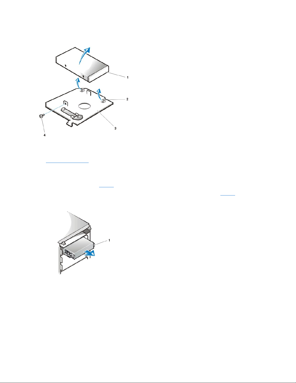
Figure 10. 3.5-Inch Diskette Drive Bracket
5.25-Inch Diskette, LS-120 SuperDisk, Tape, or CD-ROM Drive Removal
To remove a diskette, LS-120 SuperDisk, tape, or CD-ROM drive, perform the following steps:
1. Remove the computer cover.
2. Disconnect the DC power cable and interface cable from the back of the drive.
3. Squeeze the metal tabs that extend from each side of the drive bracket toward each other.
4. Pull the bracket out of the bay (see Figure 11).
5. Turn the drive/bracket assembly upside down and unscrew the four screws that secure the drive to the bracket (see Figure 12).
Figure 11. 5.25-Inch Drive Removal
Figure 12. 5.25-Inch Drive Bracket
1
3.5-inch diskette drive
2
Retaining tabs (2)
3
Bracket
4
Screw 1
Bracket tabs (2)
Page 31

5.25-Inch Diskette, Tape, or CD-ROM Drive Replacement
To install a replacement 5.25-inch diskette, tape, or CD-ROM drive, perform the following steps.
1. Unpack the replacement drive and prepare it for installation.
NOTICE: Ground yourself by either wearing a wrist grounding strap or by touching an unpainted metal surface on the
computer chassis.
Check the documentation that accompanied the drive to verify that the drive is configured for your computer system. Change any
settings necessary for your configuration.
2. If you are installing an enhanced integrated drive electronics (EIDE) drive, configure the drive for the Cable Select setting as described in
the documentation that accompanied your drive.
3. Remove the computer cover if it is not already off.
4. Remove the front panel if it is not already off.
5. Attach the new drive to the drive bracket.
Turn the drive upside down, and locate the four screw holes around its perimeter. Fit the bracket over the drive, and then tilt the front of the
drive up so that the bracket drops down into place. To ensure proper installation, all screw holes should be aligned and the tabs on the front
of the bracket should be flush with the front of the drive (see Figure 13).
To further ensure proper positioning of the drive in the chassis, insert and tighten all four screws in the order in which the holes are
numbered (the holes are marked "1" through "4" on the bracket bottom).
6. Slide the new drive into the drive bay until the drive snaps securely into place (see Figure13).
Make sure that both bracket tabs snap into place in the drive bay.
Figure 13. 5.25-Inch Drive Replacement
1
Metal tab
2
Drive bracket
3
Screws (4)
CAUTION: Before you remove the computer cover, see Precautionary Measures.
Page 32

7. Connect a DC power cable to the power input connector on the back of the drive (see Figure 14).
8. Connect the appropriate interface cable to the interface connector on the back of the drive (see Figure14).
If your system came with an EIDE CD-ROM or tape drive, use the spare connector on the existing interface cable. Otherwise, use the EIDE
interface cable provided in the drive kit.
NOTICE: You must match the colored strip on the cable with pin 1 on the drive's interface connector to avoid possible
damage to your system.
Figure 14. Attaching Cables to 5.25-Inch Drives
9. For an EIDE tape drive or CD-ROM drive, connect the other end of the interface cable to the interface connector labeled "IDE2" on the
system board.
For a diskette drive, connect the cable from the drive to the interface connector labeled "DISKETTE" on the system board.
Check all cable connections. Fold cables out of the way to provide airflow for the fan and cooling vents.
10. If the 5.25-inch drive bay was previously empty, remove the front-panel insert from the front panel.
11. Replace the front panel.
12. Replace the computer cover, reconnect your computer and peripherals to their power sources, and turn them on.
13. If the replacement drive was not identical to the drive you removed you may have to update your system configuration information in System
Setup. See the online User's Guide for more information.
For a diskette drive, update Diskette Drive A or Diskette Drive B to reflect the size and capacity of your new diskette drive.
For EIDE CD-ROM and tape drives, set the appropriate Secondary Drive 0 or Secondary Drive 1 to Auto.
14. Verify that your system works correctly by running the Dell Diagnostics (see the online System User's Guide for more information).
1
Drive
1
DC power cable
2
Power input connector
3
Interface connector
4
Interface cable
Page 33

Hard-Disk Drive Removal
1. Remove the computer cover.
2. Remove the front panel as instructed in "Front Panel."
3. Disconnect the DC power cable and EIDE or small computer system interface (SCSI) cable from the drive.
4. Pull the drive door forward and down until the hard-disk drive bracket is ejected halfway out of the chassis (see Figure 15).
5. Grasp the bracket and pull it completely out of the chassis.
Figure 15. Hard-Disk Drive Bracket Removal
Hard-Disk Drive Installation
To install a hard-disk drive, perform the following steps.
1. Remove the computer cover if it is not already off.
2. Remove the front panel if it is not already off.
3. Remove the drive bracket from the chassis as instructed in "Hard-Disk Drive Removal" if it is not already off.
4. Slide the replacement drive into the slot previously occupied by the drive you removed, oriented so that the connectors on the back of the
drive will face the back of the chassis, with the power connector located above the data/interface connector (see Figure 16).
5. Align the four screw holes of the drive and bracket. Insert and tighten the screws (see Figure16).
Figure 16. Inserting a Hard-Disk Drive in the Bracket
NOTE: Tape drives sold by Dell come with their own operating software and documentation. After you install a tape drive,
refer to the documentation that came with the drive for instructions on installing and using the tape drive software.
CAUTION: Before you remove the computer cover, see "Precautionary Measures."
1
Hard-disk drive bracket
2
Hinge tabs
3
Drive door handle
4
Drive door
CAUTION: Before you remove the computer cover, see "Precautionary Measures."
NOTE: If you are installing a replacement hard-disk drive for one containing data you want to keep, make a backup of your important files
before starting this procedure.
Page 34

6. Reinstall the hard-disk drive bracket in the chassis (see Figure 17).
Insert the bracket into the chassis by sliding it in until the tabs snap into place. Rotate the drive door up and toward the chassis until it snaps
securely into place. Be sure to fold down the drive door handle (see Figure 17) so that the front panel can be replaced on the chassis.
Figure 17. Inserting the Drive Bracket
7. Connect a DC power cable to the power input connector on the back of the drive (see Figure18).
Check all connectors to be certain that they are properly cabled and firmly seated.
8. Connect one of the device connectors on the EIDE cable to the 40-pin interface connector on the back of the hard-disk drive.
NOTICE: You must match the colored strip on the EIDE cable with pin 1 on the drive's interface connector to avoid
possible damage to your system.
Figure 18. Attaching Hard-Disk Drive Cables
1
Drive bracket
2
Drive3Screws (4)
1
Chassis drive cage
2
Drive bracket
3
Tabs
NOTE: Ultra ATA/66 hard-disk drives require an 80-conductor cable to transfer data at full speed. The 80-conductor cable
has a 40-pin connector just like the Ultra ATA/33 cable but has twice as many wires within the cable itself. If you use an Ultra
ATA/33 cable with Ultra ATA/66 hard-disk drives, the drives will transfer data at Ultra ATA/33 speeds.
Page 35

9. If it is not already connected, connect the other end of the EIDE cable to the IDE1 connector on the system board.
NOTICE: You must match the colored strip on the EIDE cable with pin 1 on the IDE1 connector to avoid possible damage to
your system.
10. Replace the computer cover and the front panel. Then reconnect your computer and peripherals to their power sources, and turn them on.
11. If the drive you just installed is the primary drive, insert a bootable diskette into drive A.
12. Enter System Setup, and update Primary Drive 0 or Primary Drive 1.
After you update the System Setup settings, reboot the system.
13. Partition and logically format your drive before proceeding to the next step.
See the documentation for your operating system for instructions.
14. Test the hard-disk drive by running the Dell Diagnostics (see the online System User's Guide for more information).
15. If the drive you just installed is the primary drive, install your operating system on the hard-disk drive.
Refer to the documentation that came with your operating system.
AGP Card Brace
To access any expansion cards and components on the system board, you must first remove the accelerated graphics port (AGP) card brace that
secures an AGP card in the AGP socket.
1. Remove the computer cover.
2. Remove the screw securing the AGP card brace through the AGP expansion card's mounting bracket to the back of the chassis (see Figure
19).
Figure 19. AGP Card Brace Removal
1
EIDE cable
2
Power input connector
3
Interface connector
4
DC power cable
CAUTION: Before you remove the computer cover, see "Precautionary Measures."
Page 36

3. Slide the card brace forward until it disengages from the slot in the card guide, then rotate the brace up and lift it away from the chassis.
To replace the card brace, perform the following steps:
1. Insert the tab on the end of the card brace into the slot above the card guide at the front of the chassis (see Figure 19).
2. Lower the card brace, ensuring that the plastic card guide on the bottom of the card brace spring engages the AGP card.
3. Slide the card brace toward the back of the system until the tab at the end engages the slot in the chassis.
4. Replace the screw that secures the AGP card brace to the chassis (see Figure19).
Expansion Cards
The Dell Precision 420 systems provide five 32-bit Peripheral Component Interconnect (PCI) expansion card slots. Slot 5 is shared with the RAID
port function.
The system contains five 32-bit expansion slots and a 32-bit AGP Pro 110 (4X) slot. If you use an AGP Pro 50 or Pro110 card, it occupies the
AGP slot and may occupy PCI slots 1 and 2. (See Figure20 for examples of these cards.)
Industry-standard architecture (ISA) expansion cads are not supported in this system.
Figure 20. Expansion Cards
Figure 21. AGP Pro110 Card Extension
1
Card guide (front of chassis)
2
AGP card brace
3
Card brace spring
4
Screw
5
Plastic card guide
6
Slot7Tab on AGP card brace
NOTE: Before disconnecting a peripheral from the system or removing a component from the system board, verify that the standby
power LED on the system board has turned off. For the location of this LED, see Figure 28.
1
32-bit PCI expansion card
2
32-bit AGP card
Page 37

Figure 21 shows the AGP card extension that occludes PCI slots 1 and 2.
The following is a list of valid expansion-card combinations:
l One AGP card and five PCI cards
l One AGP card, four PCI cards, and one RAID card
l One AGP Pro50 card and four PCI cards
l One AGP Pro50 card, three PCI cards, and one RAID card
One AGP Pro110 card and three PCI cards
l One AGP Pro110 card, two PCI cards, and one RAID card
Expansion-Card Removal
To remove an expansion card, perform the following steps.
1. Remove the computer cover.
2. Rotate the power supply away from the system board.
3. Remove the AGP card brace.
4. Disconnect any cables connected to the card.
5. Unscrew the mounting bracket screw of the card you want to remove.
6. Grasp the card by its outside corners, and ease it out of its connector.
7. If you are removing the card permanently, install a metal filler bracket over the empty card-slot opening.
Expansion-Card Installation
To install a replacement expansion card, perform the following steps.
1. Remove the computer cover.
2. Rotate the power supply away from the system board.
3. Prepare the card as necessary, using the instructions provided with the card.
4. Insert the expansion card into the expansion-card connector.
5. If the expansion card is full-length, insert the front end of the card into the corresponding card guide on the inside front of the chassis as you
insert the card into its connector. Insert the card's edge connector firmly into the expansion-card slot. Gently press the card into the connector
until it is fully seated (see Figure 22).
CAUTION: Before you remove the computer cover, see "Precautionary Measures."
NOTE: Installing filler brackets over empty card-slot openings is necessary to maintain Federal Communications Commission
(FCC) certification of the system. The brackets also keep dust and dirt out of your computer.
CAUTION: Before you remove the computer cover, see "Precautionary Measures."
Page 38
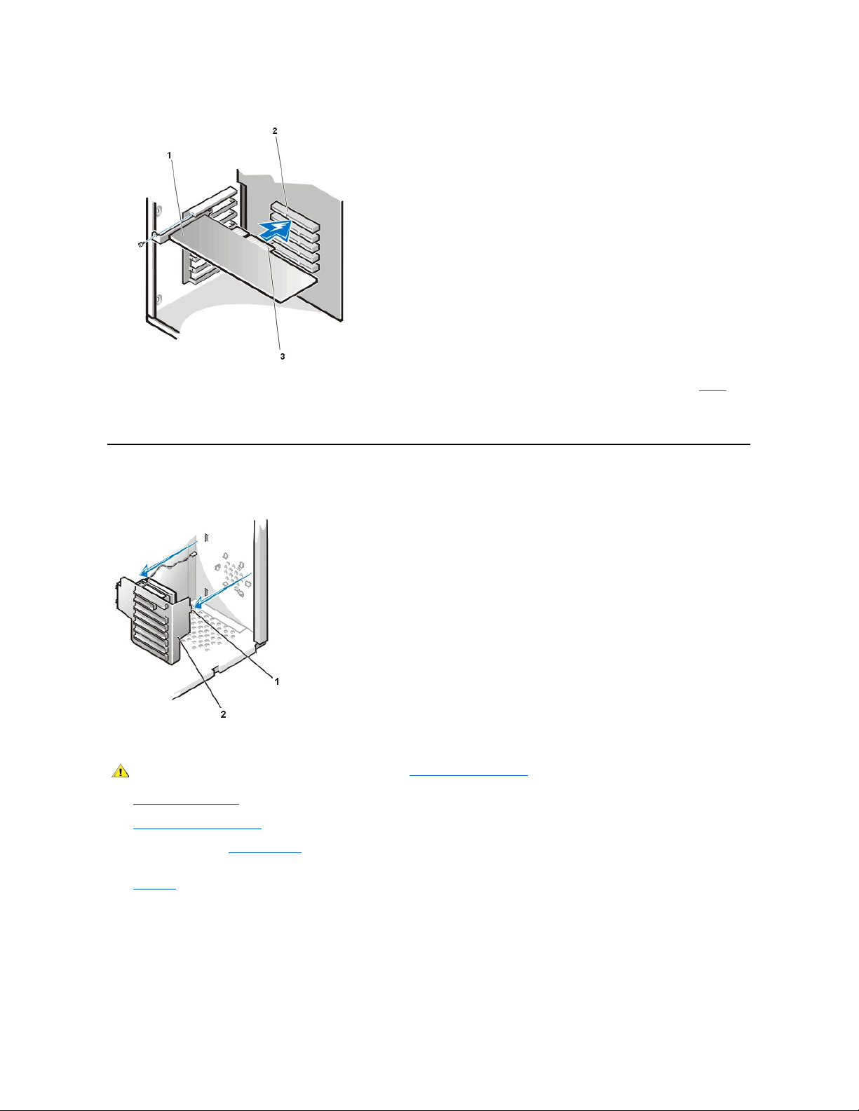
Figure 22. Installing an Expansion Card
5. When the card is firmly seated in the connector, secure the card's mounting bracket to the chassis with the screw you removed in step 5 of
the removal procedure.
6. Connect any cables that should be attached to the card.
Expansion-Card Guide and Fan
Figure 23. Expansion-Card Guide and Fan Removal
To remove the expansion-card guide and fan, perform the following steps.
1. Rotate the power supply away from the system board.
2. Remove the AGP card brace.
3. Remove all full-length expansion cards.
4. Press down on the top of the card guide to release the tab from its slot, located on the lower-left area on the front of the chassis (see
Figure23).
5. Rotate the top of the card guide away from the chassis front.
6. Disconnect the fan power cable from its connector on the system board.
7. Lift the expansion-card guide and its attached fan out of the chassis.
Figure 24. Expansion-Card Guide Fan Removal
1
Expansion card
2
Expansion-card connector
3
Card edge connector
1
Tab2Expansion-card guide
CAUTION: Before you remove the computer cover, see "Precautionary Measures."
Page 39

To remove an expansion-card guide cooling fan, perform the following steps.
1. Remove the computer cover according to the instructions in "Computer Cover."
2. Rotate the power supply.
3. Remove the expansion-card guide and fan.
4. Squeeze the tabs on the end of the fan bracket and slide the fan off of the expansion-card guide (see Figure 24).
Control Panel
Figure 25. Control Panel Removal
To remove the control panel, perform the following steps:
1. Disconnect the control panel cable from the PANEL connector on the system board (see Figure 28 for the location of the PANEL connector).
2. Remove the mounting screw that secures the control panel to the hard-disk drive cage door.
3. Disconnect the chassis intrusion switch cable connector from the control panel.
4. Disconnect the thermal cable connector from the control panel.
5. Disconnect the speaker cable connector from the control panel.
6. Remove the control panel from the chassis.
Chassis Intrusion Switch
Figure 26. Chassis Intrusion Switch Removal
1
Fan power cable
2
Fan3Plastic locking tabs (2)
CAUTION: Before you remove the computer cover, see "Precautionary Measures."
1
Control panel
2
Thermal cable connector
3
Control panel cable
4
Screw
5
Speaker cable connector
6
Chassis intrusion switch cable
connector
7
Chassis intrusion switch
8
Hard-disk drive cage door
Page 40

To remove the chassis intrusion switch and install a replacement, perform the following steps:
1. Disconnectthechassisintrusionswitchcablefromthecontrolpanel(seeFigure 26).
Note the routing of the chassis intrusion cable as you remove the cable from the chassis. The cable is routed through an enlarged hole in the
chassis and through a hole in the disk-drivecagedoor.Thechassisintrusionswitchismountedontheleftfrontofthechassis(see
Figure26).
2. Slide the chassis intrusion switch out of its slot on the chassis and carefully remove the switch and its attached cable from the chassis.
3. Install the replacement chassis intrusion switch and cable.
4. Replace the computer cover. Then reconnect your computer and peripherals to their power sources, and turn them on.
5. To reset the chassis intrusion detector, enter System Setup, select System Security, and reset Chassis Intrusion to Enabled or
Enabled-Silent (see your User's Guide for instructions).
Power Supply
To access some components on the system board, you may have to rotate the system power supply out of the way. Use this procedure to rotate
the supply out of the chassis, or to completely remove it.
To rotate or remove the power supply, perform the following steps.
1. Remove the computer cover.
2. Lay the computer on its right side (as viewed from the front).
3. Disconnect the AC power cable from the AC power receptacle on the back of the power supply (see Figure 27).
Figure 27. Rotating the Power Supply
1
Chassis intrusion cable connector
2
Control panel chassis intrusion connector
3
Enlarged hole for cable
4
Switch slot
5
Chassis intrusion switch
CAUTION: Before you remove the computer cover, see "Precautionary Measures."
NOTE: After you remove and replace the cover, the chassis intrusion detector will cause the following message to be displayed at
the next system start-up:
ALERT! Cover was previously removed.
CAUTION: Before you remove the computer cover, see "Precautionary Measures."
Page 41

4. Lift the release latch and slide the power supply about 25 mm (1 inch) toward the front of the system.
5. Continue to apply pressure on the release latch while pulling the power supply towards the front of the computer and rotating the power
supply out of the chassis.
See the instruction label on the side of the power supply for additional information.
5. To completely remove the power supply from the chassis:
a. Remove the AGP brace.
b. Remove all full-length expansion cards.
c. Remove the expansion-card guide.
d. Disconnect the DC cables connected to the drives and to the system board.
e. Using a flat-tipped screwdriver, pry out the power supply hinge pin from the chassis foot.
f. While supporting the weight of the power supply, pull the power supply hinge pin completely out to release the power supply from the
chassis.
When installing a replacement power supply, remember to rotate and secure the "L" end of the hinge pin into the groove on the chassis foot
after installing the hinge pin.
System Board Components
Figure 28 shows the system board and the location of all its sockets and connectors.
Figure 28. System Board Components
1
Power supply
2
Release latch
3
AC power receptacle
4
AC power cable
NOTE: Perform the next step only if you are completely removing the power supply from the chassis.
Page 42
1
CD-ROM drive audio connector
2
Main power 1 connector (desktop chassis)
3
Diskette connector
4
Main power 2 connector (desktop chassis)
5
Battery
6
RIMM (memory) sockets
7
SCSI narrow connector
8
Secondary EIDE connector
9
Suspend-To-RAM LED
10
Jumper block (see "System Board Jumpers")
11
System board screw
12
LVD SCSI connector
13
Primary EIDE connector
14
Standby power LED
15
Control panel connector
16
MT power 2 connector (mini tower chassis)
17
MT power 1 connector (mini tower chassis)
18
Modem (TAPI) connector
19
Card-cage fan power connector
20
Auxiliary sound input connector
21
PCI/RAID expansion card connector
22
Auxiliary hard-disk drive access LED connector
23
PCI expansion slots
24
AGP graphics slot
25
Remote wakeup on LAN connector
26
Primary processor 0 socket
27
Network cable connector
28
Diagnostic LEDs
29
USB connectors
30
Secondary processor 1 socket
31
Line-in connector
32
Line-out connector
Page 43

System Board Jumpers
Figure 29 shows the location of the jumpers on the system board. Table1 lists the system board jumpers and their settings.
Figure 29. System Board Jumpers
Jumpers are small blocks on a circuit board with two or more pins emerging from them. Plastic plugs containing a wire fit down over the pins. The
wire connects the pins and creates a circuit.
NOTICE: Make sure your system is turned off before you change a jumper setting. Otherwise, damage to your system or
unpredictable results may occur.
To change a jumper setting, pull the plug off its pin(s) and carefully fit it down onto the pin(s) indicated.
Table 1. System Board Jumper Settings
System Board Labels
Table 2 lists the labels for connectors and sockets on your system board, and it gives a brief description of their functions.
Table 2. System Board Connector and Socket Labels
33
Microphone connector
34
Mouse/keyboard (stacked)
35
System fan power connector
36
Serial port 1/ serial port 2 (stacked)
37
Parallel port/external SCSI port (stacked)
Jumper
Setting
Description
PSWD
(default)
Password features are enabled.
Password features are disabled.
RTCRST
Real-time clock reset. Can be used for troubleshooting purposes.
jumpered unjumpered
Connector or Socket Label
Description
AGP
Accelerated graphics port card socket
BATTERY
Battery socket
CD_IN
CD-ROM audio interface connector
DISKETTE
Diskette/tape drive interface connector
ENET
Integrated NIC connector
Page 44

RIMMs
To remove a Rambus in-line memory module (RIMM), perform the following steps.
1. Remove the computer cover according to the instructions in "Computer Cover."
2. Press the securing clips outward simultaneously until the RIMM disengages and pops out slightly from the socket (see Figure 30).
Figure 30. RIMM Removal
To install a RIMM, perform the following steps.
1. Remove the computer cover according to the instructions in "Computer Cover."
FAN_SYS
Microprocessor fan connector
HD_LED
Hard-disk drive LED connector
IDEn
EIDE interface connector
KYB
Keyboard connector
LINE_IN
External microphone connector
LINE_OUT
External speaker connector
MOUSE
Mouse connector
PANEL
Control panel connector
PARALLEL
Parallel port connector
PCIn
PCI expansion-card connector
POWER_1
Main power input connector
POWER_2
3.3-V power input connector
RIMMx_y
RIMM socket
SERIAL 1/2
Serial port connectors
SLOT1_PRI
Primary microprocessor connector
SLOT1_SEC
Secondary microprocessor connector
STANDBY
Standby power LED
STR_LED
Suspend-to-RAM LED
USB
USB connectors
TAPI
Telephony connector
WOL
Remote Wakeup on LAN power connector
CAUTION: Before you remove the computer cover, see "Precautionary Measures."
CAUTION: To avoid the possibility of electric shock, turn off the computer and any peripherals, disconnect them from their
electrical outlets, and then wait at least 5 seconds before you remove the computer cover.
CAUTION: The RIMMs can get extremely hot during system operation. To avoid dangerous burns, be sure that the RIMMs
have had sufficient time to cool before you touch them.
NOTE: Before disconnecting a peripheral from the system or removing a component from the system board, verify that the standby
power LED on the system board has turned off. For the location of this LED, see Figure 28.
1
Securing clips (2)
CAUTION: To avoid the possibility of electric shock, turn off the computer and any peripherals, disconnect them from their
electrical outlets, and then wait at least 5 seconds before you remove the computer cover. Also, before you upgrade memory,
see the other precautions in "Precautionary Measures. "
Page 45

2. If necessary, remove any RIMMs that occupy sockets in which you plan to install the RIMMs.
3. Install the RIMMs.
a. Locate the plastic securing clips at each end of the socket (see Figure 31).
b. Press the clips outward until they snap open.
c. Press the RIMM straight into the slot running down the center of the socket until the securing tabs snap into place around the ends
of the RIMM.
Figure 31. RIMM Installation
4. Replace the computer cover, and reconnect your computer and peripherals to their electrical outlets and turn them on.
The system detects that the new memory does not match the existing system configuration information and generates the following
message:
The amount of system memory has changed.
Strike the F1 key to continue, F2 to run the setup utility
5. Press <F2> to enter System Setup, and check the value for System Memory.
The system should have already changed the value of System Memory to reflect the newly installed memory. Verify the new total. If it is
correct, skip to step 7.
6. If the memory total is incorrect, turn off and disconnect your computer and peripherals from their electrical outlets. Remove the computer
cover, rotate the power supply, and check the installed RIMMs to make sure that they are seated properly in their sockets. Then repeat steps
3, 4, and 5.
7. Reset the chassis intrusion detector by changing Chassis Intrusion to Enabled or Enabled-Silent.
8. When the System Memory total is correct, press <Esc> to exit System Setup.
9. Run the Dell Diagnostics to verify that the RIMMs are operating properly.
Microprocessor/Heat Sink Assembly
To replace a microprocessor, perform the following steps.
NOTES: If you are not installing a replacement RIMM at this time, you MUST remove the remaining RIMM in the pair and install a pair
of continuity modules (CRIMM).
When operating with a single pair of RIMMs, they MUST occupy sockets RIMMB-1 and RIMMA-2, with CRIMMs installed in RIMMB-3
and RIMMA-4.
1
Securing clips (2)
2
Notches (2)
NOTE: After you remove and replace the cover, the chassis intrusion detector causes the following message to appear on the
screen at the next system start-up:
ALERT! Cover was previously removed.
NOTE: If a setup password has been assigned by someone else, contact your network administrator for information on resetting
the chassis intrusion detector.
NOTE: Dell recommends that only a technically knowledgeable person perform this procedure.
CAUTION: Before you remove the computer cover, see "Precautionary Measures."
Page 46

1. Remove the computer cover.
2. Rotate the power supply.
3. Remove the existing microprocessor from its connector.
Squeeze in on the two pairs of tabs on the airflow shroud and lift it away. Press outward on the guide bracket tabs to release them from the
processor/heat sink assembly. Remove the two thumbscrews. Then pull the processor/heat sink assembly out of its connector (see Figure
32). You must use up to 15 lb of force to disengage the processor from the connector.
Figure 32. Microprocessor Removal
Figure 33. Microprocessor Replacement
4. Insert the new microprocessor into the system board connector (see Figure 33).
NOTE: Before disconnecting a peripheral from the system or removing a component from the system board, verify that the standby
power LED on the system board has turned off. For the location of this LED, see Figure 28.
1
Airflow shroud
2
Thumbscrews (2)
3
Processor/heat sink assembly
4
Guide bracket
5
Second processor
1
Airflow shroud
2
Thumbscrews (2)
3
Processor/heat sink assembly
4
Guide bracket
5
Second processor
Page 47

Press the processor firmly into its connector until it is fully seated. You must use up to 25 lb of force to fully seat the processor in its connector.
5. Install the two thumbscrews.
6. Replace the airflow shroud.
7. Rotate the power supply back into position, making sure that the securing tab snaps into place.
8. Replace the computer cover, and reconnect your computer and peripherals to their power sources and turn them on.
9. Enter System Setup, and confirm that the top line in the System Data area correctly identifies the installed processor(s).
10. While in System Setup, reset the chassis intrusion detector by changing Chassis Intrusion to Enabled or Enabled-Silent.
11. Run the Dell Diagnostics to verify that the new microprocessor is operating correctly.
Microprocessor Cooling Fan
Figure 34. Microprocessor Cooling Fan Removal
To remove a microprocessor cooling fan, perform the following steps.
1. Remove the computer cover according to the instructions in "Computer Cover."
2. Rotate the power supply.
3. Remove the airflow shroud by squeezing in on the two pairs of tabs on the shroud and lift it away.
4. Remove the fan power cable from its connector (see Figure 28 for the location of the system FAN connector).
5. Gently pull the plastic locking tab, and push down on the fan to disengage the four latching tabs holding the fan to the back of the chassis.
6. Pull the fan forward (toward the microprocessor slots) to remove it.
NOTE: After you remove and replace the cover, the chassis intrusion detector will cause the following message to be
displayed at the next system start-up:
ALERT! Cover was previously removed.
NOTE: If a setup password has been assigned by someone else, contact your network administrator for information on resetting
the chassis intrusion detector.
1
Fan power cable
2
Fan3Plastic locking tab
4
Latching tabs (4)
CAUTION: Before you remove the computer cover, see "Precautionary Measures."
Page 48
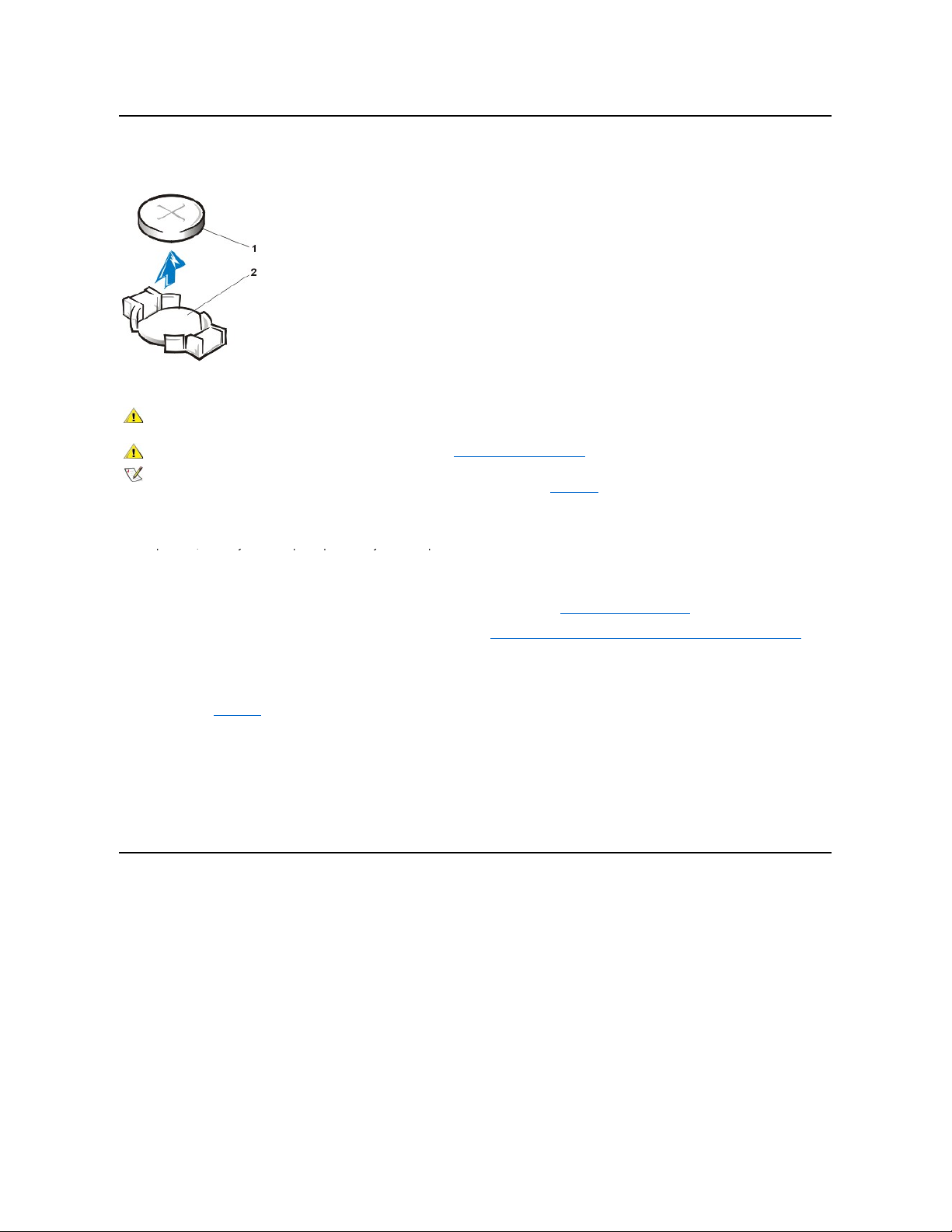
Battery
Figure 35. Battery Removal
To remove the system battery, perform the following steps:
1. If possible, enter System Setup and print the System Setup screens.
1
Battery
2
Socket
CAUTION: There is a danger of the new battery exploding if it is incorrectly installed. Replace the battery only with the same or
equivalent type recommended by the manufacturer. Discard used batteries according to the manufacturer’s instructions.
CAUTION: Before you remove the computer cover, see "Precautionary Measures."
NOTE: Before disconnecting a peripheral from the system or removing a component from the system board, verify that the standby
power LED on the system board has turned off. For the location of this LED, see Figure28.
1. If possible, enter System Setup and print the System Setup screens.
If the settings are lost while you are replacing the battery, you can refer to your written or printed cop of the system configuration information
to restore the correct settings.
2. To access the battery on the system board, rotate the power supply as described in "Rotating the Power Supply."
3. If installed, remove the CD-ROM drive according to the instructions in "Diskette, LS-120 SuperDisk, Tape, or CD-ROM Drive Removal" to
access the battery.
4. Locate the battery and remove it.
The battery is mounted in a socket labeled "BATTERY" at the upper front-right corner of the system board (as you face the side of the
system) (see Figure 28).
NOTICE: If you pry the battery out of its socket with a blunt object, be careful not to touch the system board with the object.
Make certain that the object is inserted between the battery and the socket before attempting to pry out the battery. Otherwise,
you may damage the system board by prying off the socket or by breaking circuit traces on the system board.
5. Remove the system battery by carefully prying it out of its socket with your fingers or with a blunt, nonconducting object such as a plastic
screwdriver.
When you replace the system battery, orient the new battery with the "+" facing up. Insert the battery into its socket and snap it into place.
System Board
Figure 36. System Board Removal
Page 49

To remove the system board, perform the following steps.
1. Remove the computer cover.
2. Disconnect all cables from their connectors at the back of the computer.
3. Rotate the system power supply.
4. Disconnect all cables from the system board.
5. Remove the RIMMs.
6. Remove the airflow shroud, the primary processor, and the secondary processor or terminal card.
7. Remove the AGP card brace and the AGP video card.
8. Slide all externally accessible drives and brackets partially out of the chassis.
9. Slide the hard-disk drive bracket partially out of the chassis.
10. Remove the microprocessor cooling fan.
11. Remove the screw that secures the system board to the bottom of the chassis.
12. Slide the system board toward the front of the chassis until it stops.
13. Carefully raise the front of the system board and lift the board out of the chassis at an angle.
To replace the system board, perform the following steps:
1. Carefully replace the system board in the chassis by performing steps 11 through 13 of the removal process in reverse.
2. Push down near each slot to engage the grounding clip onto its corresponding tab.
3. Push evenly on both sides of the system board as you slide and lock it into position (do not twist the system board).
4. Reinstall the mounting screw.
5. Reinstall all components on the system board by performing steps 4 through 10 of the removal process in reverse.
6. Set the jumpers on the new system board so that they are identical to those on the old board, unless you are installing a microprocessor
upgrade.
7. Replace the computer cover, connect cables, and turn on the power. Run the System Setup program to ensure that your settings are correct
and all system board components are correctly reported.
8. Run the Dell Diagnostics.
Back to Contents Page
1
System board
2
Screw
CAUTION: Before you remove the computer cover, see "Precautionary Measures."
NOTE: Before disconnecting a peripheral from the system or removing a component from the system board, verify that the standby
power LED on the system board has turned off. For the location of this LED, see Figure 28.
 Loading...