

Page 1

Dell Precision™ Workstation 390
Quick Reference Guide
Model DCTA
www.dell.com | support.dell.com
Page 2

Notes, Notices, and Cautions
NOTE: A NOTE indicates important information that helps you make better use of your computer.
NOTICE: A NOTICE indicates either potential damage to hardware or loss of data and tells you how to avoid
the problem.
CAUTION: A CAUTION indicates a potential for property damage, personal injury, or death.
Abbreviations and Acronyms
For a complete list of abbreviations and acronyms, see Glossary in your
If you purchased a Dell™ n Series computer, any references in this document to Microsoft
User’s Guide
.
®
Windows®
operating systems are not applicable.
____________________
Information in this document is subject to change without notice.
© 2006 Dell Inc. All rights reserved.
Reproduction in any manner whatsoever without the written permission of Dell Inc. is strictly forbidden.
Trademarks used in this text: Dell and the DELL logo are trademarks of Dell Inc.; Red Hat is a registered trademark of Red Hat Corporation.
Other trademarks and trade names may be used in this document to refer to either the entities claiming the marks and names or their products.
Dell Inc. disclaims any proprietary interest in trademarks and trade names other than its own.
Model DCTA
May 2006 P/N FH422 Rev. A00
Page 3

Contents
Finding Information . . . . . . . . . . . . . . . . . . . . . . . . . . . . . . . . 5
Setting Up Your Computer (Tower Orientation)
Setting Up Your Computer (Desktop Orientation)
About Your Computer
Front View (Tower Orientation)
Back View (Tower Orientation)
Front View (Desktop Orientation)
Back View (Desktop Orientation)
Back-Panel Connectors
Inside View
System Board Components
Locating Your User’s Guide
Removing the Computer Cover
Caring for Your Computer
Solving Problems
Troubleshooting Tips
. . . . . . . . . . . . . . . . . . . . . . . . . . . . . . . 19
. . . . . . . . . . . . . . . . . . . . . . . 19
. . . . . . . . . . . . . . . . . . . . . . . 21
. . . . . . . . . . . . . . . . . . . . . . 22
. . . . . . . . . . . . . . . . . . . . . . 24
. . . . . . . . . . . . . . . . . . . . . . . . . . 25
. . . . . . . . . . . . . . . . . . . . . . . . . . . . . . . . . 27
. . . . . . . . . . . . . . . . . . . . . . . . . . . . 28
. . . . . . . . . . . . . . . . . . . . . . . . . . . 29
. . . . . . . . . . . . . . . . . . . . . . . . . . 30
. . . . . . . . . . . . . . . . . . . . . . . . . . . . 31
. . . . . . . . . . . . . . . . . . . . . . . . . . . . . . . . 32
. . . . . . . . . . . . . . . . . . . . . . . . . . . . 32
Resolving Software and Hardware Incompatibilities
Using Microsoft Windows XP System Restore
Using the Last Known Good Configuration
Dell Diagnostics
Before You Start Testing
. . . . . . . . . . . . . . . . . . . . . . . . . . . . . . . 34
. . . . . . . . . . . . . . . . . . . . . . . . . . 36
. . . . . . . . . . . . . . . . . . 9
. . . . . . . . . . . . . . . . 14
. . . . . . . . . . . 32
. . . . . . . . . . . . . . . 32
. . . . . . . . . . . . . . . . . 34
Beep Codes
Diagnostic Lights
Frequently Asked Questions
. . . . . . . . . . . . . . . . . . . . . . . . . . . . . . . . . . . . 36
Error Messages
. . . . . . . . . . . . . . . . . . . . . . . . . . . . . . . 37
. . . . . . . . . . . . . . . . . . . . . . . . . . . . . . . . . 37
. . . . . . . . . . . . . . . . . . . . . . . . . . . 42
Index . . . . . . . . . . . . . . . . . . . . . . . . . . . . . . . . . . . . . . . . . 45
Contents 3
Page 4

4 Contents
Page 5
Finding Information
NOTE: Some features may not be available for your computer or in certain countries.
NOTE: Additional information may ship with your computer.
What Are You Looking For? Find It Here
• A diagnostic program for my computer
• Drivers for my computer
• My computer documentation
• My device documentation
• Desktop System Software (DSS)
• How to set up my computer
• How to care for my computer
• Basic troubleshooting information
• How to run the Dell Diagnostics
• Error codes and diagnostic lights
• How to remove and install parts
• How to open my computer cover
Drivers and Utilities CD (also known as ResourceCD)
Documentation and drivers are already installed on your
computer. You can use the CD to reinstall drivers, run
the "Dell Diagnostics" on page 34, or access your
documentation.
NOTE: Drivers and documentation updates can be found
at support.dell.com.
NOTE: The Drivers and Utilities CD is optional and may
not ship with your computer.
Quick Reference Guide
Readme files may be
included on your CD
to provide last-minute
updates about technical
changes to your
computer or advanced
technical-reference
material for technicians
or experienced users.
NOTE: The Quick Reference Guide is optional and may
not ship with your computer.
NOTE: This document is available as a PDF at
support.dell.com.
Quick Reference Guide 5
Page 6
What Are You Looking For? Find It Here
• Warranty information
Dell™ Product Information Guide
• Terms and Conditions (U.S. only)
• Safety instructions
• Regulatory information
• Ergonomics information
• End User License Agreement
• How to remove and replace parts
• Specifications
• How to configure system settings
• How to troubleshoot and solve problems
• Service Tag and Express Service Code
• Microsoft Windows License Label
User’s Guide
Microsoft
®
Windows® XP Help and Support Center
1
Click the
2
Click
Start
User’s and system guides
button and click
Help and Support
and click
User’s guides
.
The User’s Guide is also available on the optional Drivers
CD
and Utilities
.
Service Tag and Microsoft Windows License
These labels are located on your computer.
• Use the Service Tag
to identify your
computer when you
support.dell.com
use
or contact technical
support.
• Enter the Express
Service Code to direct your call when contacting
technical support.
.
6 Quick Reference Guide
Page 7

What Are You Looking For? Find It Here
• Solutions — Troubleshooting hints and tips, articles
from technicians, online courses, frequently asked
questions
• Community — Online discussion with other Dell
customers
• Upgrades — Upgrade information for components,
such as memory, the hard drive, and the operating
Dell Support Website — support.dell.com
NOTE: Select your region to view the appropriate support
site.
NOTE: Corporate, government, and education customers
can also use the customized Dell Premier Support website
at premier.support.dell.com. The website may not be
available in all regions.
system
• Customer Care — Contact information, service call
and order status, warranty, and repair information
• Service and support — Service call status and support
history, service contract, online discussions with
technical support
• Reference — Computer documentation, details on
my computer configuration, product specifications,
and white papers
• Downloads — Certified drivers, patches, and
software updates
• Desktop System Software (DSS) — If you reinstall
the operating system for your computer, you should
also reinstall the DSS utility. DSS provides critical
updates for your operating system and support for
Dell™ 3.5-inch USB floppy drives, Intel
Pentium
®
M processors, optical drives, and USB
®
devices. DSS is necessary for correct operation of
your Dell computer. The software automatically
detects your computer and operating system and
installs the updates appropriate for your
configuration.
• How to use Windows XP
• Documentation for my computer
• Documentation for devices (such as a modem)
Windows Help and Support Center
1
Click the
2
Type a word or phrase that describes your problem
and click the arrow icon.
3
Click the topic that describes your problem.
4
Follow the instructions on the screen.
Start
button and click
Help and Support
.
Quick Reference Guide 7
Page 8

What Are You Looking For? Find It Here
• How to reinstall my operating system
Operating System CD
The operating system is already installed on your
computer. To reinstall your operating system, use the
Operating System CD. See your User’s Guide for
instructions.
NOTE: The color of your CD varies based on the operating
system you ordered.
NOTE: The Operating System CD is optional and may
not ship with your computer.
• How to use Linux
• E-mail discussions with users of Dell Precision™
products and the Linux operating system
• Additional information regarding Linux
and my Dell Precision computer
Dell Supported Linux Sites
• http://linux.dell.com
• http://lists.us.dell.com/mailman/listinfo/linux-precision
• http://docs.us.dell.com/docs/software/oslinux/
After you reinstall your
operating system, use
the optional Drivers and
Utilities CD to reinstall
drivers for the devices
that came with your
computer.
Your operating system
product key label is
located on your
computer.
8 Quick Reference Guide
Page 9
Setting Up Your Computer (Tower Orientation)
CAUTION: Before you begin any of the procedures in this section, follow the safety instructions located
in the Product Information Guide.
You must complete all steps to properly set up your computer.
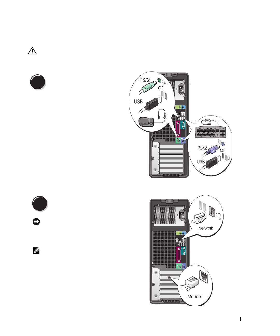
Connect the keyboard and the mouse.
1
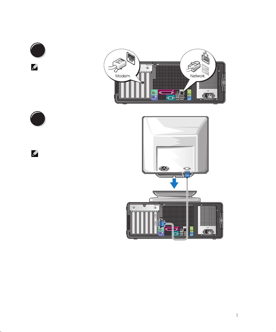
Connect the modem or the network cable.
2
NOTICE: Do not connect a modem cable to the
network adapter. Voltage from telephone
communications can damage the network adapter.
NOTE: If your computer has a network card installed,
connect the network cable to the card.
Quick Reference Guide 9
Page 10
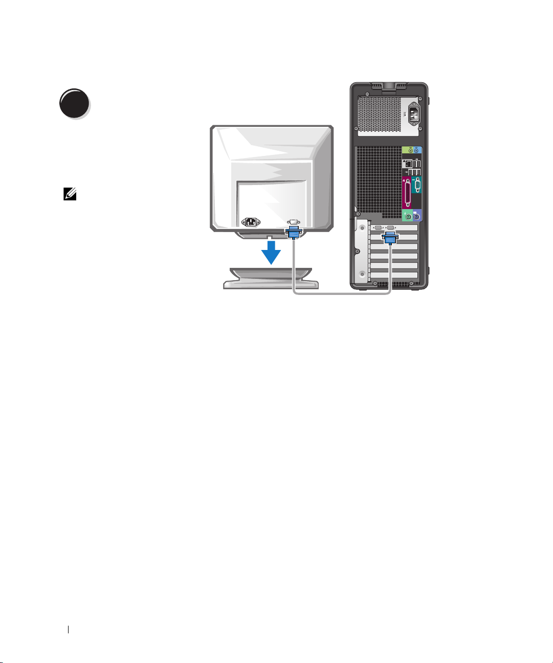
Connect the monitor.
3
Depending on your graphics
card, you can connect your
monitor in various ways.
NOTE: You may need to use
the provided adapter or
cable to connect your
monitor to the computer.
10 Quick Reference Guide
Page 11
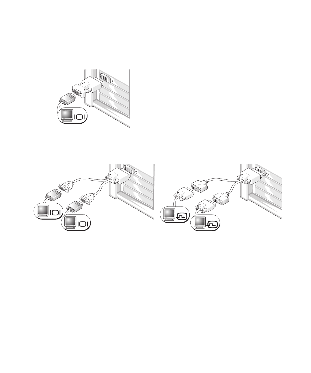
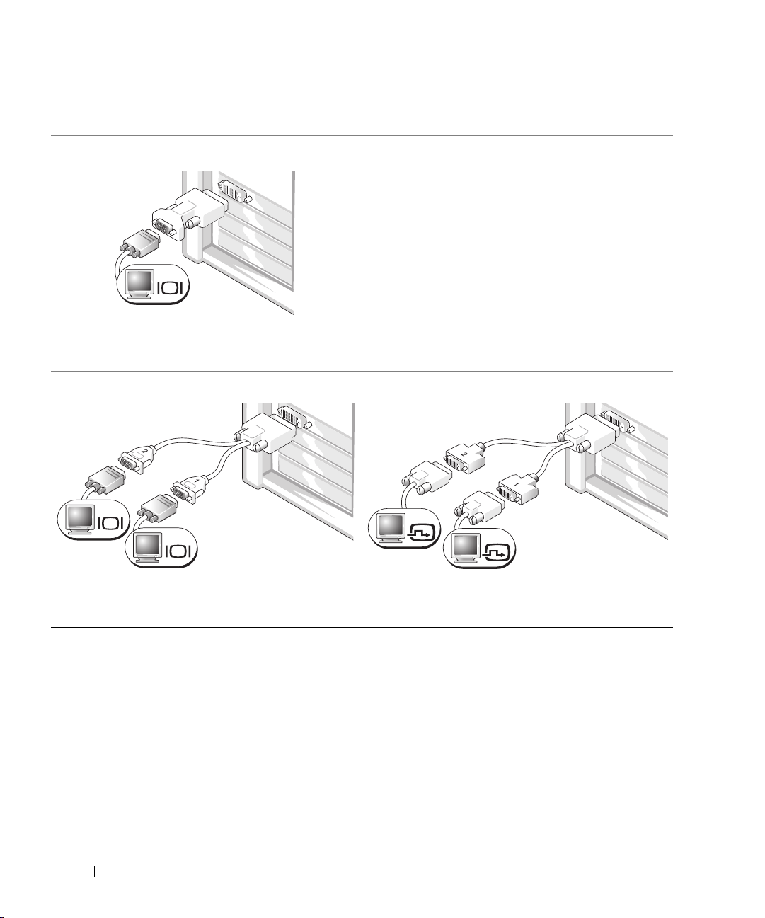
For single- and dual-monitor capable cards with a single connector
One VGA Adapter
VGA
Use the VGA adapter when you have a single-monitor
graphics card and you want to connect your computer
to a VGA monitor.
Dual VGA Y Cable Adapter
Dual DVI Y Cable Adapter
VGA
VGA
Use the appropriate Y cable when your graphics card
has a single connector and you want to connect your
computer to one or two VGA monitors.
Use the appropriate Y cable when your graphics card has a
single connector and you want to connect your computer
to one or two DVI monitors.
DVI
DVI
The dual-monitor cable is color coded; the blue connector is for the primary monitor, and the black
connector is for the secondary monitor. To enable dual-monitor support, both monitors must be attached
to the computer when it starts.
Quick Reference Guide 11
Page 12
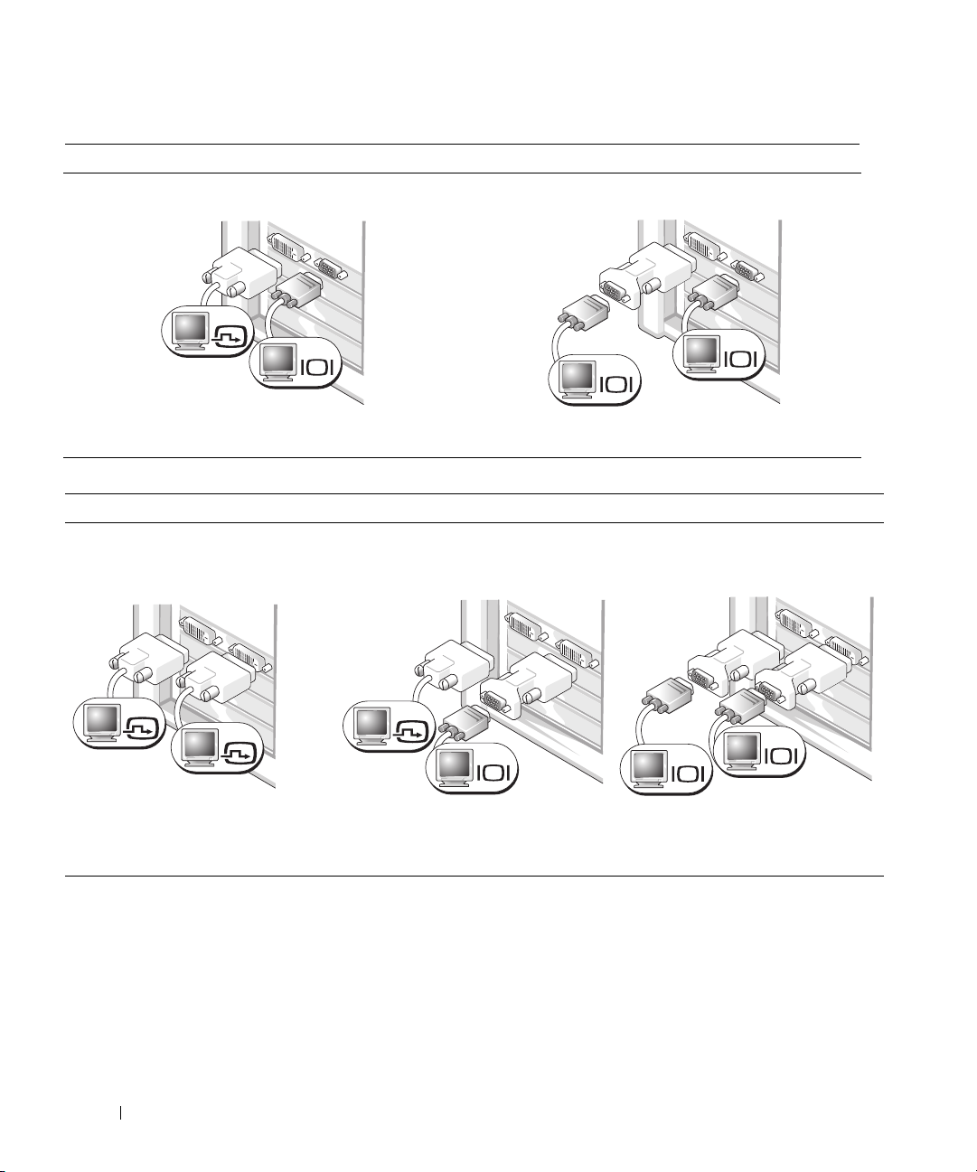
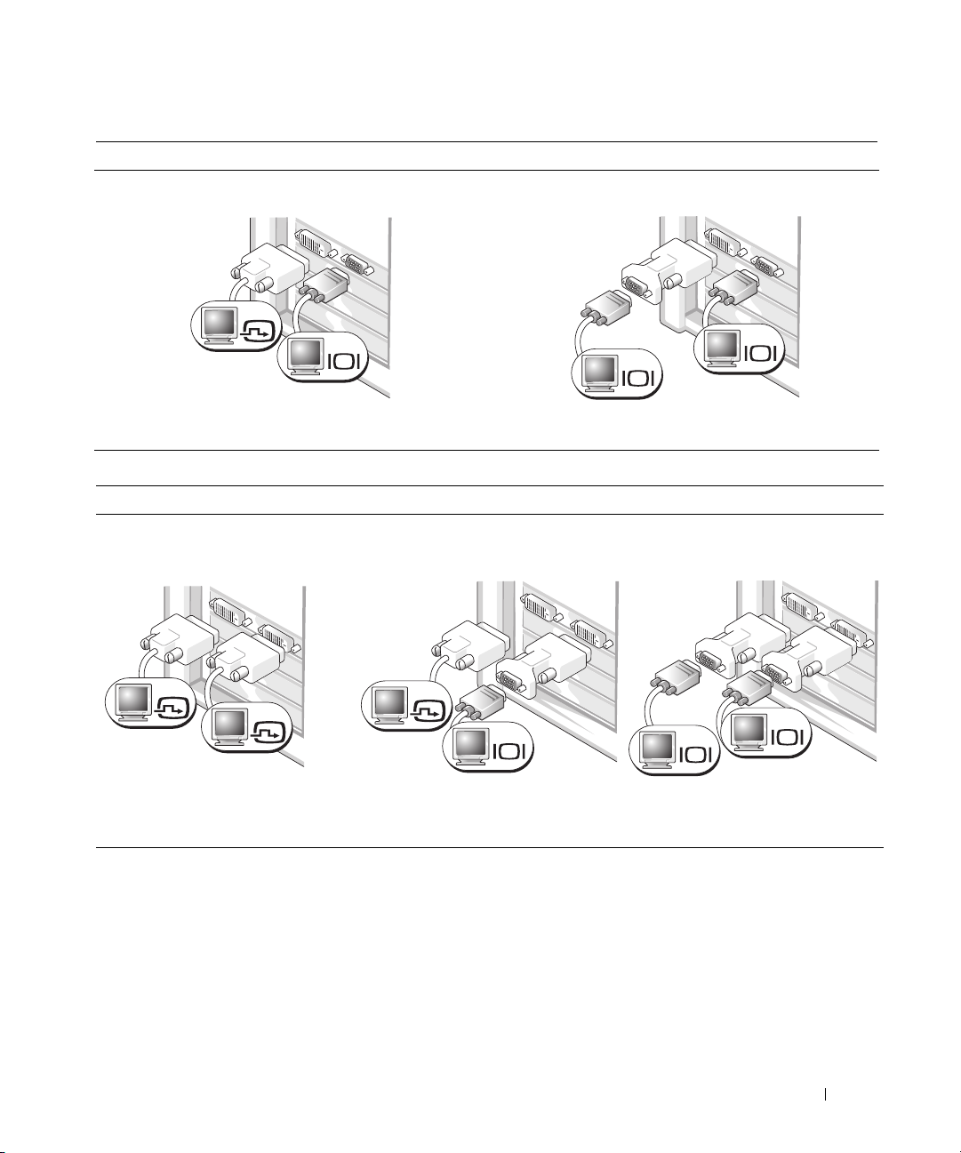
For dual-monitor capable cards with one DVI connector and one VGA connector
One DVI Connector and One VGA Connector
DVI
VGA
Two VGA Connectors With One VGA Adapter
VGA
VGA
Use the appropriate connector(s) when you want
to connect your computer to one or two monitors.
For dual-monitor capable cards with two DVI connectors
Two DVI Connectors
Two DVI Connectors With One VGA
Adapter
DVI
DVI
Use the DVI connectors to connect
your computer to one or two DVI
monitors.
Use the VGA adapter to connect
a VGA monitor to one of the DVI
connectors on your computer
DVI
Use the VGA adapter when you want to connect
your computer to two VGA monitors.
Two DVI Connectors With Two VGA
Adapters
VGA
VGA
VGA
Use two VGA adapters to connect
two VGA monitors to the DVI
connectors on your computer.
12 Quick Reference Guide
Page 13
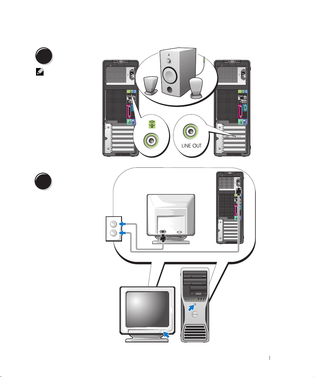
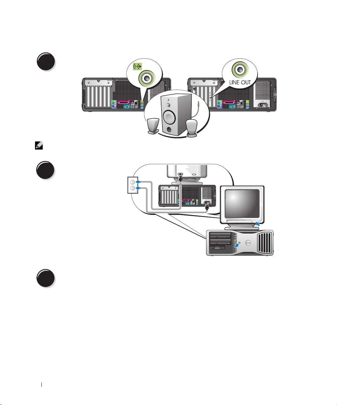
Connect the
4
speakers.
NOTE: If your
computer has a sound
card installed, connect
the speakers to the
card.
Connect the power
5
cables and turn on
the computer and
monitor.
Quick Reference Guide 13
Page 14
Install additional software or devices.
6
Before you install any devices or software that did not come with your computer, read the documentation
that came with the software or device or contact the vendor to verify that the software or device is
compatible with your computer and operating system.
Congratulations! You have completed the setup for your tower computer.
Setting Up Your Computer (Desktop Orientation)
CAUTION: Before you begin any of the procedures in this section, follow the safety instructions located
in the Product Information Guide.
You must complete all steps to properly set up your computer.
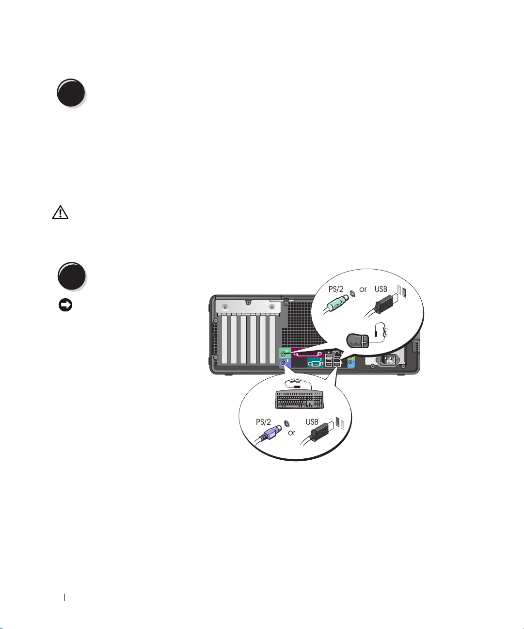
Connect the keyboard and the mouse.
1
NOTICE: Do not connect a
modem cable to the network
adapter. Voltage from
telephone communications
can damage the network
adapter.
14 Quick Reference Guide
Page 15
Connect the modem
2
or the network cable.
NOTE: If your computer
has a network card
installed, connect the
network cable to the card.
Connect the monitor.
3
Depending on your graphics card,
you can connect your monitor in
various ways.
NOTE: You may need to use the
provided adapter or cable to connect
your monitor to the computer.
Quick Reference Guide 15
Page 16
For single- and dual-monitor capable cards with a single connector
VGA Adapter
VGA
Use the VGA adapter when you have a single monitor
graphics card and you want to connect your computer
to a VGA monitor.
Dual VGA Y Cable Adapter
Dual DVI Y Cable Adapter
VGA
VGA
Use the appropriate Y cable when your graphics card
has a single connector and you want to connect your
computer to one or two VGA monitors.
Use the appropriate Y cable when your graphics card has a
single connector and you want to connect your computer
to one or two DVI monitors.
DVI
DVI
The dual-monitor cable is color coded; the blue connector is for the primary monitor, and the black
connector is for the secondary monitor. To enable dual-monitor support, both monitors must be attached
to the computer when it starts.
16 Quick Reference Guide
Page 17
For dual-monitor capable cards with one DVI connector and one VGA connector
One DVI Connector and One VGA Connector
DVI
VGA
Two VGA Connectors With One VGA Adapter
VGA
VGA
Use the appropriate connector(s) when you want
to connect your computer to one or two monitors.
For dual-monitor capable cards with two DVI connectors
Two DVI Connectors
Two DVI Connectors With One VGA
Adapter
DVI
DVI
Use the DVI connector(s) to connect
your computer to one or two DVI
monitors.
Use the VGA adapter to connect a
VGA monitor to one of the DVI
connectors on your computer.
DVI
Use the VGA adapter when you want to connect
your computer to two VGA monitors.
Two DVI Connectors With Two VGA
Adapters
VGA
VGA
VGA
Use two VGA adapters to connect
two VGA monitors to the DVI
connectors on your computer.
Quick Reference Guide 17
Page 18
Connect the speakers.
4
NOTE: If your computer has a sound card installed, connect the speakers to the card.
Connect the power cables
and turn on the computer
5
and monitor.
Your desktop computer has an
optional front IEEE 1394
connector. This connector is only
available if you purchased an
IEEE 1394 card. To purchase
a card, contact Dell. For
instructions on contacting Dell
and for more information on the
IEEE 1394 card, see your
Guide
.
User’s
Install additional software or devices.
6
Before you install any devices or software that did not come with your computer, read the documentation
that came with the software or device or contact the vendor to verify that the software or device is
compatible with your computer and operating system.
Congratulations! You have completed the setup for your desktop computer.
18 Quick Reference Guide
Page 19
About Your Computer
1
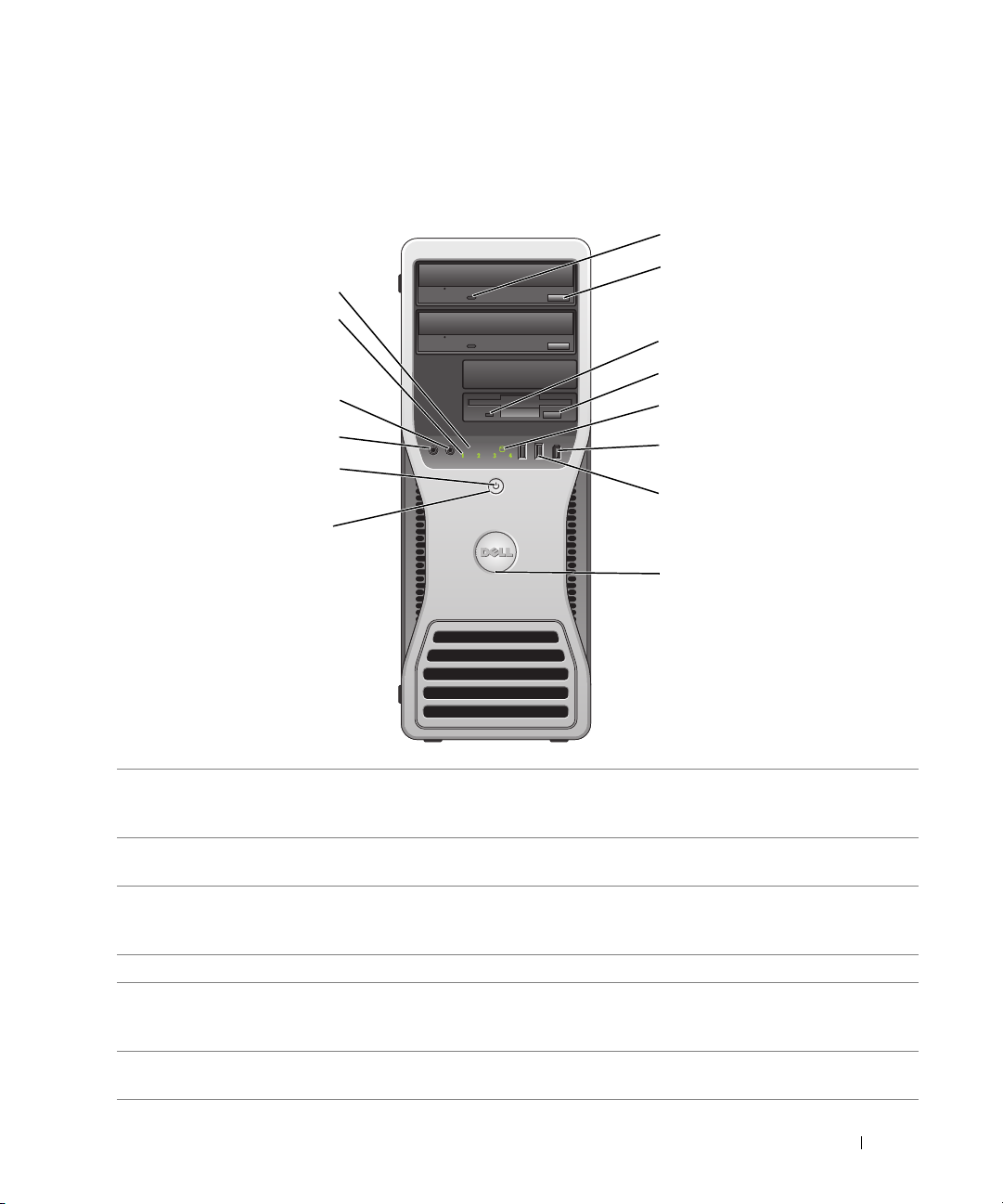
Front View (Tower Orientation)
14
13
12
2
3
4
5
11
10
9
1 CD- or DVD-drive
activity light
2 CD- or DVD-drive
eject button
3 floppy-drive activity
light
4 floppy-drive eject button Press this button to eject a floppy disk from the optional floppy drive.
5 hard-drive activity light The hard-drive activity light is on when the computer reads data from or writes
6 IEEE 1394 connector
(optional)
The CD/DVD-drive activity light is on when the computer reads data from or
writes data to the CD/DVD drive. Wait until this light turns off before you remove
the CD or DVD from the drive.
Press this button o eject a disc from the CD or DVD drive.
The floppy-drive activity light is on when the computer reads data from or writes
data to the optional floppy drive. Wait until this light turns off before you remove
the floppy from the drive.
data to the hard drive. The light might also be on when a device such as your CD
player is operating.
Use the optional IEEE 1394 connectors for high-speed data devices such as digital
video cameras and external storage devices.
6
7
8
Quick Reference Guide 19
Page 20

7 USB 2.0 connectors (2) Use the USB connectors on the front of your computer for devices that you
connect occasionally, such as flash memory keys or cameras, or for bootable USB
devices (see
to a USB device).
It is recommended that you use the back USB connectors for devices that typically
remain connected, such as printers and keyboards.
8 Dell badge rotation
notch
9 power button Press this button to turn the computer on.
To rotate the badge, place your fingers around the outside of the badge, press in,
and turn the badge. You can also rotate the badge by using the slot provided near
the bottom of the badge.
"System Setup" in your
User’s Guide for more information on booting
NOTE: The power button can also be used to wake the system or to place it into
a power-saving mode. See "Power Management" in the User’s Guide for more
information.
NOTICE: To avoid losing data, do not use the power button to turn the
computer off. Instead, perform an operating system shutdown.
10 power light The power light illuminates and blinks or remains solid to indicate different states:
• No light — The computer is turned off.
• Steady green — The computer is in a normal operating state.
• Blinking green — The computer is in a power-saving mode.
• Blinking or solid amber — See "Power Problems" in the
To exit from a power-saving mode, press the power button or use the keyboard or
the mouse if it is configured as a wake device in the Windows Device Manager. For
more information about sleep modes and exiting from a power-saving mode, see
"Power Management" in the User’s Guide.
See "Diagnostic Lights" on page 37 for a description of light codes that can help
you troubleshoot problems with your computer.
11 microphone connector Use the microphone connector to attach a personal computer microphone for
voice or musical input into a sound or telephony program.
12 headphone connector Use the headphone connector to attach headphones and most kinds of speakers.
13 diagnostic lights (4) Use the lights to help you troubleshoot a computer problem based on the
diagnostic code. For more information, see "Diagnostic Lights" on page 37.
14 network link light The network light is on when the computer sends or receives data over a network
connection. The light might also be on when a network device is establishing a
network connection.
User’s Guide
.
20 Quick Reference Guide
Page 21
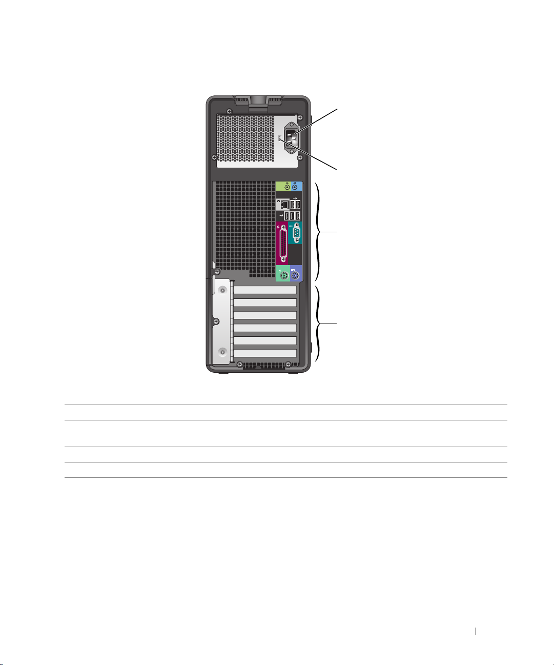
Back View (Tower Orientation)
1
2
3
4
1 power connector Insert the power cable into this connector.
2 voltage selection switch See the safety instructions located in the Product Information Guide for more
information.
3 back-panel connectors Plug serial, USB, and other devices into the appropriate connector.
4 card slots Access connectors for any installed PCI or PCI Express cards.
Quick Reference Guide 21
Page 22
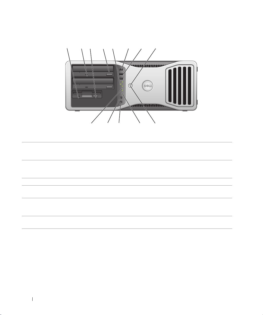
Front View (Desktop Orientation)
1 2 7
3
5 6 8
4
910111213
1 floppy-drive activity
light
2 CD- or DVD-drive
activity light
3 floppy-drive eject button Press this button to eject a floppy disk from the optional floppy drive.
4 CD- or DVD-drive
eject button
5 hard-drive activity light The hard-drive activity light is on when the computer reads data from or writes
6 IEEE 1394 connector
(optional)
The floppy-drive activity light is on when the computer reads data from or writes
data to the optional floppy drive. Wait until this light turns off before you remove
the floppy from the drive.
The CD/DVD-drive activity light is on when the computer reads data from or
writes data to the CD/DVD drive. Wait until this light turns off before you remove
the CD or DVD from the drive.
Press this button to eject a disc from the CD or DVD drive.
data to the hard drive. The light might also be on when a device such as your CD
player is operating.
Use the optional IEEE 1394 connectors for high-speed data devices such as digital
video cameras and external storage devices.
22 Quick Reference Guide
Page 23

7 USB 2.0 connectors (2) Use the USB connectors on the front of the computer for devices that you connect
occasionally, such as flash memory keys or cameras, or for bootable USB devices
(see
"System Setup" in your
device).
It is recommended that you use the back USB connectors for devices that typically
remain connected, such as printers and keyboards.
8 power button Press this button to turn the computer on.
User’s Guide for more information on booting to a USB
NOTE: The power button can also be used to wake the system or to place it into a
power-saving mode. See "Power Management" in the User’s Guide" for more
information.
NOTICE: To avoid losing data, do not use the power button to turn the
computer off. Instead, perform an operating system shutdown.
9 power light The power light illuminates and blinks or remains solid to indicate different states:
• No light — The computer is turned off.
• Steady green — The computer is in a normal operating state.
• Blinking green — The computer is in a power-saving mode.
• Blinking or solid amber — See "Power Management" in the User’s Guide."
To exit from a power-saving mode, press the power button or use the keyboard or
the mouse if it is configured as a wake device in the Windows Device Manager. For
more information about sleep modes and exiting from a power-saving mode, see
"Power Management" in the User’s Guide for more information. See "Diagnostic
Lights" on page 37 for a description of light codes that can help you troubleshoot
problems with your computer.
10 diagnostic lights (4) Use the lights to help you troubleshoot a computer problem based on the
diagnostic code. For more information See "Diagnostic Lights" on page 37.
11 microphone connector Use the microphone connector to attach a personal computer microphone
for voice or musical input into a sound or telephony program.
12 headphone connector Use the headphone connector to attach headphones and most kinds of speakers.
13 network link light The network light is on when the computer sends or receives data over a network
connection. The light might also be on when a network device is establishing a
network connection.
Quick Reference Guide 23
Page 24
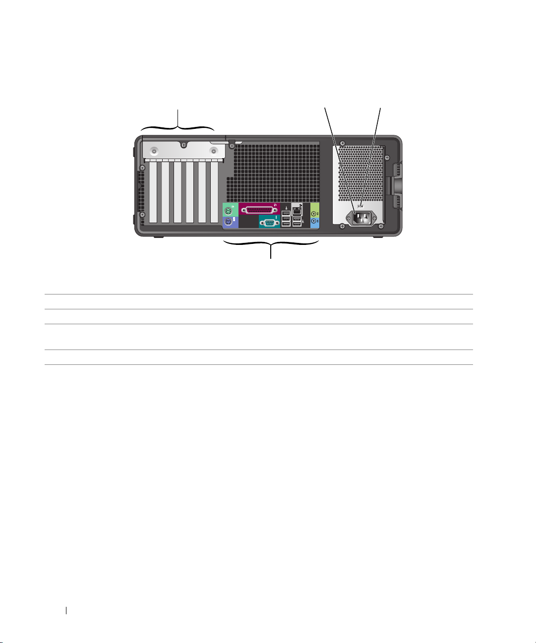
Back View (Desktop Orientation)
32
1
4
1 card slots Access connectors for any installed PCI or PCI Express cards.
2 power connector Insert the power cable into this connector.
3 voltage selection switch See the safety instructions located in the Product Information Guide for more
information.
4 back-panel connectors Plug serial, USB, and other devices into the appropriate connector.
24 Quick Reference Guide
Page 25
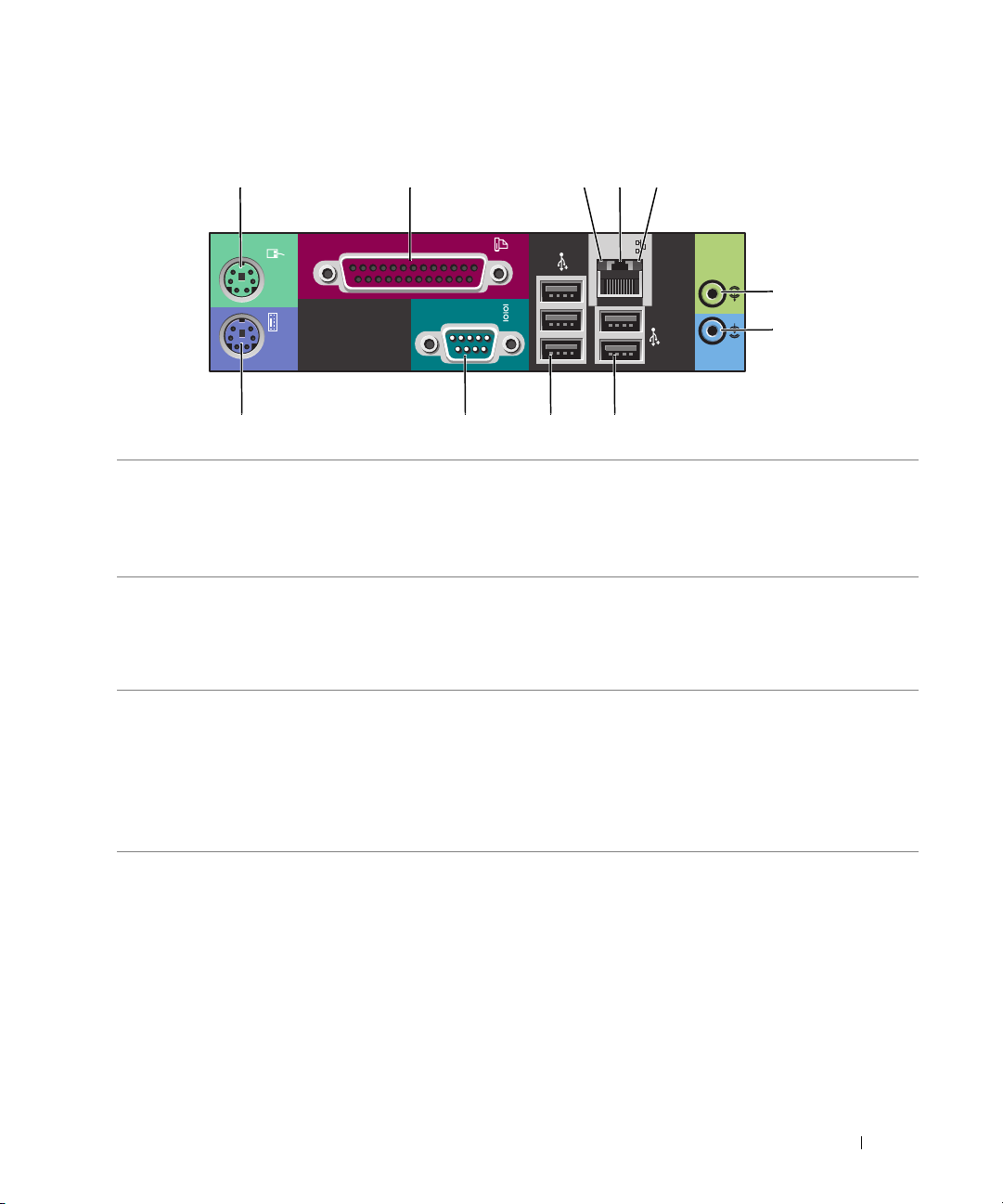
Back-Panel Connectors
1
2 345
6
7
891011
1 mouse connector Plug a standard mouse into the green mouse connector. Turn off the computer
and any attached devices before you connect a mouse to the computer. If you have
a USB mouse, plug it into a USB connector.
If your computer is running the Microsoft
the necessary mouse drivers have been installed on your hard drive.
2 parallel connector Connect a parallel device, such as a printer, to the parallel connector. If you have
a USB printer, plug it into a USB connector.
NOTE: The integrated parallel connector is automatically disabled if the computer
detects an installed card containing a parallel connector configured to the same
address. For more information, see "System Setup Options" in the User’s Guide.
3 link integrity light
• Green — A good connection exists between a 10-Mbps network and the
computer.
• Orange — A good connection exists between a 100-Mbps network and the
computer.
• Yellow — A good connection exists between a 1000-Mbps (or 1-Gbps) network
and the computer.
• Off — The computer is not detecting a physical connection to the network.
®
Windows XP operating system,
Quick Reference Guide 25
Page 26

4 network adapter
connector
To attach your computer to a network or broadband device, connect one end of
a network cable to either a network jack or your network or broadband device.
Connect the other end of the network cable to the network adapter connector
on your computer. A click indicates that the network cable has been securely
attached.
NOTE: Do not plug a telephone cable into the network connector.
On computers with an additional network connector card, use the connectors
on the card and on the back of the computer when setting up multiple network
connections (such as a separate intra- and extranet).
It is recommended that you use Category 5 wiring and connectors for your
network. If you must use Category 3 wiring, force the network speed to 10 Mbps
to ensure reliable operation.
5 network activity light Flashes a yellow light when the computer is transmitting or receiving network
data. A high volume of network traffic may make this light appear to be in a steady
"on" state.
6 line-in connector Use the blue line-in connector to attach a record/playback device such as a cassette
player, CD player, or VCR.
On computers with a sound card, use the connector on the card.
7 line-out connector Use the green line-out connector to attach headphones and most speakers
with integrated amplifiers.
On computers with a sound card, use the connector on the card.
8 USB 2.0 connectors (2) Use the back USB connectors for devices that typically remain connected,
such as printers and keyboards.
It is recommended that you use the front USB connectors for devices that you
connect occasionally, such as flash memory keys or cameras., or for bootable USB
devices.
9 USB 2.0 connectors (3) Use the back USB connectors for devices that typically remain connected,
such as printers and keyboards.
It is recommended that you use the front USB connectors for devices that you
connect occasionally, such as flash memory keys or cameras, or for bootable USB
devices.
10 serial connector Connect a serial device, such as a handheld device, to the serial port. The default
designations are COM1 for serial connector 1 and COM2 for the optional serial
connector 2.
For more information, see "System Setup Options" in the User’s Guide
11 keyboard connector If you have a standard keyboard, plug it into the purple keyboard connector.
If you have a USB keyboard, plug it into a USB connector.
.
26 Quick Reference Guide
Page 27
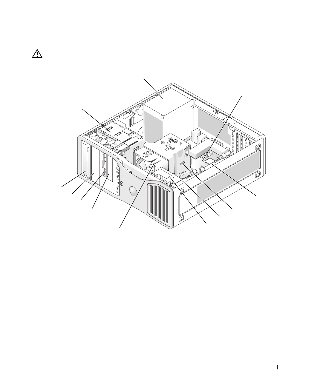
Inside View
1
CAUTION: Before you begin any of the procedures in this section, follow the safety instructions located
in the Product Information Guide.
2
12
11
10
9
8
7
6
4
5
3
1 power supply 7 processor fan
2 system board 8 lower 3.5 inch drive bay
3 secondary hard drive bay 9 upper 3.5 inch drive bay
4 processor airflow shroud 10 lower 5.25 inch drive bay
5 primary hard drive bay 11 upper 5.25 inch drive bay
6 card fan 12 drive cage
Quick Reference Guide 27
Page 28
Cable Colors
1
2
34 5
Device Color
Hard drive blue cable
Floppy drive black pull tab
CD/DVD drive orange pull tab
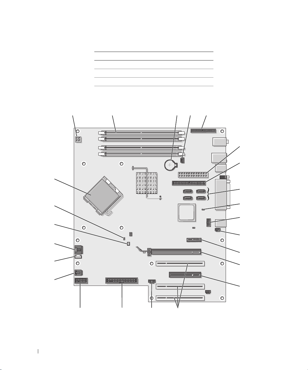
System Board Components
6
24
23
22
21
20
19
18
17
1516
7
8
9
10
11
12
13
14
28 Quick Reference Guide
Page 29

1 power connector (12VPOWER) 13 PCI-Express x16 up to 150w card slot
2 memory module connectors 14 PCI-Express x8 card slot (wired as x4)
3 battery socket (BATTERY) 15 PCI card slots (1-3)
4 memory fan connector (FAN_MEM) 16 external LED connector (AUX LED)
5 front panel connector 17 floppy drive (FLOPPY)
6 main power connector (POWER) 18 serial connector (SERIAL2)
7 IDE drive connector (IDE) 19 card cage fan (FAN CARD CAGE)
8 SATA connectors (SATA-1, SATA-3,
SATA-0, SATA-2)
9 RTC reset jumper (RTCRST) 21 processor fan connector (FAN_CPU)
10 Flexbay connector (FLEXBAY) 22 processor fan thermal sensor connector (THRM)
11 chassis intrusion header 23 password jumper (PSWD)
12 PCI-Express x1 card slot 24 processor connector (CPU)
20 internal speaker connector (INT_SPKR)
Locating Your User’s Guide
Your
User’s Guide
• Technical specifications
• Information for changing the orientation of your computer from a desktop to a tower
• Front and back views of your computer, including all of the available connectors
• Inside views of your computer, including a detailed graphic of the system board and the connectors
• Instructions for cleaning your computer
• Information on software features, such as LegacySelect Technology control, using a password,
and system setup options
• Tips and information for using the Microsoft Windows XP operating system
• Instructions for removing and installing parts, including memory, cards, drives, the microprocessor,
and the battery
• Information for troubleshooting various computer problems
• Instructions for using the Dell Diagnostics and reinstalling drivers
• Information on how to contact Dell
You can access the
contains additional information about your computer such as:
User’s Guide
from your hard drive or the Dell Support website at
support.dell.com
.
Quick Reference Guide 29
Page 30

To access the User’s Guide from your hard drive:
Click the
To access your User’s Guide from the Dell Support website:
1
2
3
Start
button and click
Go to
support.dell.com
Help and Support
.
.
Follow the prompts on the website that ask you for information specific to your computer.
At the Dell Support website home page, click
Reference
, click
User’s Guides
, click
Systems
and then select your computer.
Removing the Computer Cover
CAUTION: Before you begin any of the procedures in this section, follow the safety instructions located
in the Product Information Guide.
CAUTION: To guard against electrical shock, always unplug your computer from the electrical outlet before
removing the cover.
NOTICE: Before touching anything inside your computer, ground yourself by touching an unpainted metal surface,
such as the metal at the back of the computer. While you work, periodically touch an unpainted metal surface to
dissipate any static electricity that could harm internal components.
NOTICE: To avoid losing data, save and close any open files and exit any open programs before you turn off your
computer.
1
Shut down the operating system:
a
Save and close any open files, exit any open programs, click the
Off Computer
b
In the
Turn off computer
.
window, click
Tur n o ff
.
The computer turns off after the operating system shutdown process finishes.
Start
button, and then click
,
Tu r n
2
Ensure that the computer and any attached devices are turned off. If your computer and attached
devices did not automatically turn off when you shut down your operating system, turn them off now.
3
If you have installed a security cable, remove it from the security cable slot.
NOTICE: Ensure that you are working on a level, protected surface to avoid scratching either the computer or the
surface on which it is resting.
4
Lay your computer on a flat surface with the computer cover facing up.
5
Pull back the cover latch release.
30 Quick Reference Guide
Page 31

cover latch release
hinge tabs (3)
computer cover
6
Locate the three hinge tabs on the edge of the computer.
7
Grip the sides of the computer cover and pivot the cover up, using the hinges as leverage points.
8
Release the cover from the hinge tabs and set it aside in a secure location.
Caring for Your Computer
To help maintain your computer, follow these suggestions:
• To avoid losing or corrupting data, never turn off your computer when the hard drive light is on.
• Schedule regular virus scans using virus software.
• Manage hard drive space by periodically deleting unnecessary files and defragmenting the drive.
• Back up files on a regular basis.
• Periodically clean your monitor screen, mouse, and keyboard (see your
information).
User’s Guide
Quick Reference Guide 31
for more
Page 32

Solving Problems
Troubleshooting Tips
Perform the following checks when you troubleshoot your computer:
• If you added or removed a part before the problem started, review the installation procedures
and ensure that the part is correctly installed.
• If a peripheral device does not work, ensure that the device is properly connected.
• If an error message appears on the screen, write down the exact message. The message may help
technical support personnel diagnose and fix the problem(s).
• If an error message occurs in a program, see the program’s documentation.
• If the recommended action in the troubleshooting section is to see a section in your
go to
support.dell.com (on another computer if necessary) to access your
User’s Guide.
User’s Guide
Resolving Software and Hardware Incompatibilities
If a device is either not detected during the operating system setup or is detected but incorrectly configured,
you can use the Hardware Troubleshooter to resolve the incompatibility.
To resolve incompatibilities using the Hardware Troubleshooter:
1
Click the
2
Ty p e
3
Click
4
In the
and click
Start
button and click
hardware troubleshooter
Hardware Troubleshooter
Hardware Troubleshooter
Next
.
Help and Support
in the
list, click
.
in the
Search
field and click the arrow to start the search.
Search Results
I need to resolve a hardware conflict on my computer
list.
,
,
Using Microsoft Windows XP System Restore
The Microsoft Windows XP operating system provides System Restore to allow you to return your computer
to an earlier operating state (without affecting data files) if changes to the hardware, software, or other
system settings have left the computer in an undesirable operating state. See the Windows Help and
Support Center (see "Finding Information" on page 5) for information about using System Restore.
NOTICE: Make regular backups of your data files. System Restore does not monitor your data files or recover
them.
Creating a Restore Point
1
Click the
2
Click
3
Follow the instructions on the screen.
32 Quick Reference Guide
Start
button and click
System Restore
Help and Support
.
.
Page 33

Restoring the Computer to an Earlier Operating State
NOTICE: Before you restore the computer to an earlier operating state, save and close any open files and exit any
open programs. Do not alter, open, or delete any files or programs until the system restoration is complete.
1
Click the
Restore
2
Ensure that
3
Click a calendar date to which you want to restore your computer.
The
Start
button, point to
All Programs→
.
Restore my computer to an earlier time
Select a Restore Point
screen provides a calendar that allows you to see and select restore points.
Accessories→
System Tools
is selected and click
, and then click
Next
.
System
All calendar dates with available restore points appear in boldface type.
4
Select a restore point and click
Next
.
If a calendar date has only one restore point, then that restore point is automatically selected. If two
or more restore points are available, click the restore point that you prefer.
5
Click
Next
.
Restoration Complete
The
screen appears after System Restore finishes collecting data and then
the computer restarts.
6
After the computer restarts, click OK.
To change the restore point, you can either repeat the steps using a different restore point, or you can
undo the restoration.
Undoing the Last System Restore
NOTICE: Before you undo the last system restore, save and close all open files and exit any open programs.
Do not alter, open, or delete any files or programs until the system restoration is complete.
1
Click the
Restore
2
Click
3
Click
The
4
After the computer restarts, click OK.
Enabling System Restore
Start
button, point to
.
Undo my last restoration
Next
.
System Restore
screen appears and the computer restarts.
All Programs→ Accessories→ System Tools
and click
Next
.
, and then click
System
If you reinstall Windows XP with less than 200 MB of free hard-disk space available, System Restore
is automatically disabled. To see if System Restore is enabled:
1
Click the
2
Click
3
Click
Start
button and click
Control Pane l
Performance and Maintenance
System
.
.
.
Quick Reference Guide 33
Page 34

4
Click the
5
Ensure that
System Restore
tab.
Turn off System Restore
is unchecked.
Using the Last Known Good Configuration
1
Restart your computer and press <F8> when the message
system to start
2
Highlight
Last Known Good Configuration
appears.
, press <Enter>, press <l>, and then select your
Please select the operating
operating system when prompted.
Other Options to Help Resolve Additional Device or Software Conflicts
NOTICE: The following processes erase all of the information on your hard drive.
• Reinstall your operating system using the operating system installation guide and
Operating System
CD.
During the operating system reinstallation, you can select to delete the existing partitions and reformat
your hard drive.
• Reinstall all drivers, beginning with the chipset, using the
Drivers and Utilities
CD
.
Dell Diagnostics
CAUTION: Before you begin any of the procedures in this section, follow the safety instructions located
in the Product Information Guide.
When to Use the Dell Diagnostics
If you experience a problem with your computer, perform the checks in "Solving Problems" on page 32
and run the Dell Diagnostics before you contact Dell for technical assistance.
It is recommended that you print these procedures before you begin.
NOTICE: The Dell Diagnostics works only on Dell™ computers. Using this program with other computers can
cause incorrect computer responses or result in error messages.
The Dell Diagnostics allow you to:
• Perform quick checks or extensive tests on one or all devices
• Choose how many times a test is run
• Display or print test results or save them in a file
• Suspend testing if an error is detected or terminate testing if a certain number of errors occur
Help
• Access online
screens that describe the tests and how to run them
• Read status messages that tell you whether tests completed successfully
• Receive error messages if problems are detected
34 Quick Reference Guide
Page 35

Starting the Dell Diagnostics From Your Hard Drive
1
Turn on (or restart) your computer.
2
When the DELL™ logo appears, press <F12> immediately.
NOTE: If you see a message stating that no diagnostics utility partition has been found, see "Starting the Dell
Diagnostics From the Drivers and Utilities CD" on page 35.
If you wait too long and the operating system logo appears, continue to wait until you see the
Microsoft Windows desktop. Then shut down your computer and try again. For more information on
shutting down your computer, see your
3
When the boot device list appears, highlight
4
When the Dell Diagnostics
on the tests, see your
Starting the Dell Diagnostics From the Drivers and Utilities CD
1
Insert the
2
Shut down and restart the computer. For more information on shutting down your computer,
see your
3
When the DELL logo appears, press <F12> immediately.
Drivers and Utilities
User’s Guide.
Main Menu
User’s Guide.
CD.
User’s Guide.
Boot to Utility Partition
and press <Enter>.
appears, select the test you want to run. For more information
If you wait too long and the Windows logo appears, continue to wait until you see the Windows
desktop. Then shut down your computer and try again. For more information on shutting down your
computer, see your
NOTE: The next steps change the boot sequence for one time only. On the next start-up, the computer boots
according to the devices specified in system setup.
4
When the boot device list appears, highlight
5
Select the
6
Select the
7
Ty p e 1 to start the ResourceCD menu.
8
Ty p e 2 to start the Dell Diagnostics.
9
Select
IDE CD-ROM Device
Boot from CD-ROM
Run the 32 Bit Dell Diagnostics
User’s Guide.
IDE CD-ROM Device
and press <Enter>.
option from the CD boot menu.
option from the menu that appears.
from the numbered list. If multiple versions are listed, select
the version appropriate for your computer.
10
When the Dell Diagnostics
on the tests, see your
Main Menu
User’s Guide.
appears, select the test you want to run. For more information
Quick Reference Guide 35
Page 36

Before You Start Testing
CAUTION: Before you begin any of the procedures in this section, follow the safety instructions in the Product
Information Guide.
• Turn on your printer if one is attached.
• Enter system setup, review your computer’s configuration information, and enable all of your
computer’s components and devices, such as connectors.
Beep Codes
Your computer might emit a series of beeps during start-up if the monitor cannot display errors or problems.
This series of beeps, called a beep code, identifies a problem. One possible beep code (code 1-3-1) consists
of one beep, a burst of three beeps, and then one beep. This beep code tells you that the computer
encountered a memory problem.
If a beep code is emitted, write it down and look it up in the following table.
Code Cause
1-1-2 Microprocessor register failure
1-1-3 NVRAM read/write failure
1-1-4 ROM BIOS checksum failure
1-2-1 Programmable interval timer failure
1-2-2 DMA initialization failure
1-2-3 DMA page register read/write failure
1-3 Video Memory Test failure
1-3-1 through 2-4-4 Memory not being properly identified or used
1-3-2 Memory problem
3-1-1 Slave DMA register failure
3-1-2 Master DMA register failure
3-1-3 Master interrupt mask register failure
3-1-4 Slave interrupt mask register failure
3-2-2 Interrupt vector loading failure
3-2-4 Keyboard Controller Test failure
3-3-1 NVRAM power loss
3-3-2 Invalid NVRAM configuration
3-3-4 Video Memory Test failure
3-4-1 Screen initialization failure
36 Quick Reference Guide
Page 37

Code Cause
3-4-2 Screen retrace failure
3-4-3 Search for video ROM failure
4-2-1 No timer tick
4-2-2 Shutdown failure
4-2-3 Gate A20 failure
4-2-4 Unexpected interrupt in protected mode
4-3-1 Memory failure above address 0FFFFh
4-3-3 Timer-chip counter 2 failure
4-3-4 Time-of-day clock stopped
4-4-1 Serial or parallel port test failure
4-4-2 Failure to decompress code to shadowed memory
4-4-3 Math-coprocessor test failure
4-4-4 Cache test failure
Error Messages
NOTE: If the message is not listed, see the documentation for either the operating system or the program that was
running when the message appeared.
If an error occurs during start-up, a message may be displayed on the monitor identifying the problem.
See "Error Messages" in the
User’s Guide
for suggestions on resolving any problems.
Diagnostic Lights
CAUTION: Before you begin any of the procedures in this section, follow the safety instructions located
in the Product Information Guide.
To help you troubleshoot a problem, your computer has four lights labeled "1," "2," "3," and "4" on the front.
The lights can be off or green. When the computer starts normally, the lights flash. After the computer
starts, all four lights display solid green briefly and then turn off to indicate normal operation. If the
computer malfunctions, the pattern of the lights identify the problem.
Light Pattern Problem Description Suggested Resolution
The computer is in a normal off
condition or a possible pre-BIOS
failure has occurred.
NOTE: The diagnostic lights turn off after
a short time if the computer is in a normal
operating condition after POST.
Plug the computer into a working
electrical outlet and press the power
button.
Quick Reference Guide 37
Page 38

Light Pattern Problem Description Suggested Resolution
A possible BIOS failure has occurred;
the computer is in the recovery mode.
Run the BIOS Recovery utility, wait for
recovery completion, and then restart
the computer.
A possible processor failure
has occurred.
Reinstall the processor and restart
the computer.
Memory modules are detected,
but a memory failure has occurred.
1
Reseat the memory modules to ensure
that your computer is successfully
communicating with the memory.
2
Restart the computer.
3
If the problem still exists, remove all
the memory modules and install one
memory module in memory module
connector 4.
4
Restart the computer.
The following message appears:
Alert! Operating in Debug
Mode. Please Populate
Memory in Pairs for Normal
Operation
5
Press <F1> to boot to the operating
.
system.
6
Run the Dell Diagnostics. See page 34
for instructions.
7
If the memory module passes, shut
down the computer, remove the
memory module, and then repeat the
process with the remaining memory
modules until a memory error occurs
during start-up or diagnostic testing.
If the first memory module tested is
defective, repeat the process with the
remaining modules to ensure that the
remaining modules are not defective.
8
When the defective memory module
is identified, contact Dell for a
replacement. For instructions on
contacting Dell, see your
User’s Guide
NOTE: If necessary, the computer can
operate in debug mode until new memory
modules are installed.
.
38 Quick Reference Guide
Page 39

Light Pattern Problem Description Suggested Resolution
A possible expansion card failure
has occurred.
1
Determine if a conflict exists by
removing a card (not the graphics
card) and then restarting the
computer. For more information
on removing a card, see your
.
Guide
2
If the problem persists, reinstall
the card that you removed, remove
a different card, and then restart
the computer.
3
Repeat this process for each card.
If the computer starts normally,
troubleshoot the last card removed
from the computer for resource
conflicts (see"Resolving Software and
Hardware Incompatibilities" on
page 32).
4
If the problem persists, contact Dell.
For instructions on contacting Dell,
A possible graphics card failure
has occurred.
see your
• If the computer has a graphics card,
remove the card, reinstall it, and
User’s Guide
then restart the computer.
• If the problem still exists, install a
graphics card that you know works
and restart the computer.
• If the problem persists or the
computer has integrated graphics,
contact Dell. For instructions on
contacting Dell, see your
A possible floppy or hard drive failure
has occurred.
Reseat all power and data cables
and restart the computer.
User’s
.
User’s Guide.
A possible USB failure has occurred. Reinstall all USB devices, check cable
connections, and then restart the
computer.
Quick Reference Guide 39
Page 40

Light Pattern Problem Description Suggested Resolution
No memory modules are detected. 1
Reseat the memory modules to ensure
that your computer is successfully
communicating with the memory.
2
Restart the computer.
3
If the problem still exists, remove all
the memory modules and install one
memory module in memory module
connector 4.
4
Restart the computer.
The following message appears:
Alert! Operating in Debug
Mode. Please Populate
Memory in Pairs for Normal
Operation
5
Press <F1> to boot to the operating
.
system.
6
Run the Dell Diagnostics. See page 34
for instructions.
7
If the memory module passes, shut
down the computer, remove the
memory module, and then repeat the
process with the remaining memory
modules until a memory error occurs
during start-up or diagnostic testing.
If the first memory module tested is
defective, repeat the process with the
remaining modules to ensure that the
remaining modules are not defective.
8
When the defective memory module
is identified, contact Dell for a
replacement.For instructions on
contacting Dell, see your
NOTE: If necessary, the computer can
operate in debug mode until new memory
modules are installed.
System board failure has occurred. Contact Dell for technical assistance.
For instructions on contacting Dell,
see your User’s Guide.
User’s Guide.
40 Quick Reference Guide
Page 41

Light Pattern Problem Description Suggested Resolution
Memory modules are detected, but a
memory configuration or compatibility
error exists.
• Ensure that no special memory
module/memory connector placement
requirements exist.
• Verify that the memory modules that
you are installing are compatible with
your computer.
• Reinstall the memory modules and
restart the computer.
• If the problem persists, contact Dell.
For instructions on contacting Dell,
User’s Guide.
A possible system board resource
and/or hardware failure has occurred.
see your
• Perform the procedures in "Resolving
Software and Hardware
Incompatibilities" on page 32.
• If the problem persists, contact Dell.
For instructions on contacting Dell,
User’s Guide.
A possible expansion card failure
has occurred.
see your
1
Determine if a conflict exists by
removing a card (not a graphics card)
and restarting the computer.
2
If the problem persists, reinstall the
card that you removed, remove a
different card, and then restart the
computer.
3
Repeat this process for each card.
If the computer starts normally,
troubleshoot the last card removed
from the computer for resource
conflicts (see "Resolving Software and
Hardware Incompatibilities" on
page 32).
4
If the problem persists, contact Dell.
For instructions on contacting Dell,
Another failure has occurred.
This pattern also displays when
you enter system setup and may
not indicate a problem.
see your
• Ensure that the cables are properly
connected to the system board from
the hard drive, CD drive, and DVD
drive.
User’s Guide.
• If the problem persists, contact Dell.
For instructions on contacting Dell,
see your
User’s Guide.
Quick Reference Guide 41
Page 42

Light Pattern Problem Description Suggested Resolution
The computer is in a normal operating
condition after POST.
None.
NOTE: The diagnostic lights turn off after
a short time if the computer is in a normal
operating condition after POST.
Frequently Asked Questions
How Do I... Solution Where to Find Additional Information
Set up my computer to use two
monitors?
Connect my monitor when the
monitor cable connector doesn’t
seem to fit the connector on the
back of my computer?
Connect my speakers? If you have a sound card installed,
If your computer has the required
graphics card to support dualmonitor setup, then look in your
shipping box for a Y-cable. The Ycable has a single connector on one
end (plug this connector into the
back panel) and branches into two
connectors (plug these connectors
into the monitor cables). For the
tower computer, see page 10 and for
the desktop computer, see page 15.
If your graphics card has a DVI
connector but your monitor has a
VGA connector, then you need to use
an adapter. An adapter should be
included in the shipping box.
connect the speakers to the
connectors on the card. For the tower
computer, see page 13 and for the
desktop computer, see page 18.
See "Setting Up Your Computer
(Tower Orientation)" on page 9 or
"Setting Up Your Computer
(Desktop Orientation)" on page 14
for information on connecting dual
monitors to your computer.
See "Setting Up Your Computer
(Tower Orientation)" on page 9 or
"Setting Up Your Computer
(Desktop Orientation)" on page 14
for information on connecting
monitors to your computer. For
more information, contact Dell.
For information on contacting Dell,
see your User’s Guide.
See the documentation that came
with your speakers for more
information.
42 Quick Reference Guide
Page 43

How Do I... Solution Where to Find Additional Information
Find the right connectors for my
USB or IEEE 1394 devices?
Locate information about the
hardware and other technical
specifications for my computer?
Find documentation for my
computer?
Your tower computer has eight USB
connectors (two on the front, one
internal, and five on the back).
Your desktop computer has eight
USB connectors (two on the front,
one internal, and five on the back)
and an optional front IEEE 1394
connector. This connector is only
available if you purchased an IEEE
1394 card. To purchase a card,
contact Dell. For more information
on the IEEE 1394 card, see your
User’s Guide.
Yo u r User’s Guide has a
specifications table that provides
more detailed information about
your computer and the hardware.
To locate your User’s Guide,
see "Finding Information" on page 5.
The following documentation is
available for your computer:
• User’s Guide
• Product Information Guide
• System Information Label
To locate these documents, see
"Finding Information" on page 5.
See "About Your Computer" on
page 19 for illustrations of the front
and back views of your computer.
For help locating your User’s Guide,
see "Finding Information" on page 5.
Go to the Dell Support website at
support.dell.com and use one of the
following support tools: read white
papers on the latest technology or
communicate with other Dell users
at the Dell forum chat room.
If you lose your documentation, it is
available on the Dell Support website
at support.dell.com.
Quick Reference Guide 43
Page 44

44 Quick Reference Guide
Page 45

Index
B
beep codes, 36
C
cards
slots, 21, 24
CD drive
eject button, 19, 22
computer
beep codes, 36
restore to previous state, 32
conflicts
software and hardware
incompatibilities, 32
connectors
headphone, 20, 23
IEEE, 19, 22
keyboard, 26
line-in, 26
line-out, 26
mouse, 25
network adapter, 26
parallel, 25
power, 21, 24
serial, 26
sound, 26
USB, 20, 23, 26
D
Dell
support site, 7
Dell Diagnostics, 34
Dell Premier Support
website, 6-7
diagnostic lights, 37
diagnostics
beep codes, 36
Dell, 34
Drivers and Utilities CD, 5
lights, 20, 23, 37
documentation
device, 5
online, 7
Product Information Guide, 6
Quick Reference, 5
ResourceCD, 5
User’s Guide, 6
drivers
ResourceCD, 5
Drivers and Utilities CD, 5
DVD drive
eject button, 19, 22
E
error messages
beep codes, 36
diagnostic lights, 37
F
floppy drive
activity light, 19, 22
eject button, 19, 22
H
hard drive
activity light, 19-20, 22-23
hardware
beep codes, 36
conflicts, 32
Dell Diagnostics, 34
Hardware Troubleshooter, 32
headphone
connector, 20, 23
Help and Support Center, 7
I
IEEE
connectors, 19, 22
installing parts
turning off your computer, 30
IRQ conflicts, 32
K
keyboard
connector, 26
Index 45
Page 46

L
P
T
labels
Microsoft Windows, 6
Service Tag, 6
lights
back of computer, 37
diagnostic, 20, 23, 37
floppy drive activity, 19, 22
hard drive activity,
19-20, 22-23
link integrity, 25
network, 25-26
network activity, 26
power, 20, 23
M
Microsoft Windows label, 6
motherboard.
See system board
mouse
connector, 25
N
network
connector, 26
O
Operating System
CD, 8
Installation Guide, 8
power
button, 20, 23
connector, 21, 24
light, 20, 23
problems
beep codes, 36
conflicts, 32
Dell Diagnostics, 34
diagnostic lights, 37
restore to previous state, 32
R
reinstalling
Drivers and Utilities CD, 5
ResourceCD, 5
ResourceCD
Dell Diagnostics, 34
S
safety instructions, 6
Service Tag, 6
software
conflicts, 32
sound connectors
line-in, 26
line-out, 26
system board, 28
System Restore, 32
troubleshooting
conflicts, 32
Dell Diagnostics, 34
diagnostic lights, 37
Hardware Troubleshooter, 32
Help and Support Center, 7
restore to previous state, 32
U
USB
connectors, 20, 23, 26
User’s Guide, 6
V
voltage selection
switch, 21, 24
W
warranty, 6
Windows XP
Hardware Troubleshooter, 32
Help and Support Center, 7
System Restore, 32
46 Index
Page 47

Station de travail
Dell Precision™ 390
Guide de référence rapide
Modèle DCTA
www.dell.com | support.dell.com
Page 48

Remarques, avis et précautions
REMARQUE : une REMARQUE indique des informations importantes qui peuvent vous aider à mieux utiliser
votre ordinateur.
AVIS : un AVIS vous avertit d'un risque de dommage matériel ou de perte de données et vous indique comment éviter
le problème.
PRÉCAUTION : une PRÉCAUTION indique un risque potentiel d'endommagement du matériel, de blessure corporelle
ou de mort.
Abréviations et sigles
Pour obtenir la liste complète des abréviations et des acronymes, reportez-vous au glossaire du
Guide d'utilisation
Si vous avez acheté un ordinateur Dell™ série n, aucune des références faites dans ce document aux systèmes
d'exploitation Microsoft
®
Windows® n'est applicable.
____________________
Les informations contenues dans ce document peuvent être modifiées sans préavis.
© 2006 Dell Inc. Tous droits réservés.
La reproduction de ce document de quelque manière que ce soit sans l'autorisation écrite de Dell Inc. est strictement interdite.
Marques utilisées dans ce document : Dell et le logo DELL sont des marques de Dell Inc. ; Red Hat est une marque déposée de Red Hat
Corporation.
Tous les autres noms de marques et marques commerciales utilisés dans ce document se rapportent aux sociétés propriétaires des marques et
des noms de ces produits. Dell Inc. décline tout intérêt dans l'utilisation des marques déposées et des noms de marques ne lui appartenant pas.
.
Modèle DCTA
Mai 2006 P/N FH422 Rev. A00
Page 49

Sommaire
Recherche d'informations . . . . . . . . . . . . . . . . . . . . . . . . . . . . 51
Configuration de l'ordinateur (mode tour)
. . . . . . . . . . . . . . . . . . . . 56
Configuration de l'ordinateur (mode bureau)
Présentation de l'ordinateur
Vue avant (mode tour)
Vue arrière (mode tour)
Vue avant (mode bureau)
Vue arrière (mode bureau)
Connecteurs du panneau arrière
Vue interne
. . . . . . . . . . . . . . . . . . . . . . . . . . . . . . . . . 74
Composants de la carte système
Comment consulter le Guide d'utilisation
Retrait du capot de l'ordinateur
Entretien et maintenance de l'ordinateur
Résolution des incidents
Conseils de dépannage
. . . . . . . . . . . . . . . . . . . . . . . . . . . 66
. . . . . . . . . . . . . . . . . . . . . . . . . . . 66
. . . . . . . . . . . . . . . . . . . . . . . . . . . 68
. . . . . . . . . . . . . . . . . . . . . . . . . . 69
. . . . . . . . . . . . . . . . . . . . . . . . . 71
. . . . . . . . . . . . . . . . . . . . . . 72
. . . . . . . . . . . . . . . . . . . . . . . . 75
. . . . . . . . . . . . . . . . . . . . 76
. . . . . . . . . . . . . . . . . . . . . . . . . 77
. . . . . . . . . . . . . . . . . . . . 78
. . . . . . . . . . . . . . . . . . . . . . . . . . . . . 79
. . . . . . . . . . . . . . . . . . . . . . . . . . . 79
Résolution des incompatibilités liées aux logiciels
ou au matériel
. . . . . . . . . . . . . . . . . . . . . . . . . . . . . . . . 79
Utilisation de la fonction Restauration du système
sous Microsoft Windows XP
. . . . . . . . . . . . . . . . . . . . . . . . 79
Utilisation de la dernière configuration valide
Dell Diagnostics
Avant de commencer un test
. . . . . . . . . . . . . . . . . . . . . . . . . . . . . . . 81
. . . . . . . . . . . . . . . . . . . . . . . . 83
. . . . . . . . . . . . . . . . . . 61
. . . . . . . . . . . . . . . 81
Codes sonores
Messages d'erreur
Voyants de diagnostic
Questions fréquemment posées
. . . . . . . . . . . . . . . . . . . . . . . . . . . . . . . . . . 83
. . . . . . . . . . . . . . . . . . . . . . . . . . . . . 84
. . . . . . . . . . . . . . . . . . . . . . . . . . . . . . 85
. . . . . . . . . . . . . . . . . . . . . . . . . 90
Index . . . . . . . . . . . . . . . . . . . . . . . . . . . . . . . . . . . . . . . . . 93
Sommaire 49
Page 50

50 Sommaire
Page 51

Recherche d'informations
REMARQUE : certaines fonctions ne sont disponibles que dans certains pays et sur certains modèles
d'ordinateurs.
REMARQUE : des informations supplémentaires peuvent être fournies avec l'ordinateur.
Que recherchez-vous ? Reportez-vous aux éléments suivants...
• Un programme de diagnostic pour mon ordinateur
• Des pilotes pour mon ordinateur
• La documentation concernant mon ordinateur
• La documentation concernant mes périphériques
• Le logiciel DSS (Desktop System Software)
CD Drivers and Utilities (également appelé ResourceCD)
La documentation et les pilotes sont déjà installés sur
l'ordinateur. Vous pouvez utiliser le CD pour réinstaller
les pilotes, exécuter Dell Diagnostics (voir “Dell
Diagnostics”, à la page 81) ou accéder à la documentation.
Des fichiers “readme”
(lisez-moi) peuvent être
inclus sur votre CD afin
de fournir des mises à
jour de dernière minute
concernant des modifications techniques
apportées au système
ou des informations de
référence destinées aux
techniciens ou aux utilisateurs expérimentés.
REMARQUE : les mises à jour relatives aux pilotes
et à la documentation sont disponibles à l'adresse
support.dell.com.
REMARQUE : le CD Drivers and Utilities n'est fourni
qu'avec certains ordinateurs.
Guide de référence rapide 51
Page 52

Que recherchez-vous ? Reportez-vous aux éléments suivants...
• Comment configurer mon ordinateur
• Comment entretenir mon ordinateur
• Des informations de base concernant le dépannage
• Comment exécuter Dell Diagnostics
• Une description des codes d'erreur et des voyants
de diagnostic
• Comment retirer et installer des pièces
• Comment ouvrir le capot de mon ordinateur
Guide de référence rapide
REMARQUE : le CD Drivers and Utilities est disponible
uniquement en option. Il est possible qu'il n'ait pas été livré
avec l'ordinateur.
REMARQUE : ce document est disponible au format PDF
à l'adresse support.dell.com.
• Des informations sur la garantie
• Les termes et conditions de la garantie
(États-Unis uniquement)
• Des consignes de sécurité
• Des informations sur les réglementations
• Des informations sur l'ergonomie
• Le contrat de licence utilisateur final
Guide d'informations sur le produit Dell™
52 Guide de référence rapide
Page 53

Que recherchez-vous ? Reportez-vous aux éléments suivants...
• Comment retirer et remettre en place
des composants
• Des spécifications
• Comment configurer les paramètres système
• Comment identifier et résoudre les incidents
Guide d'utilisation
Centre d'aide et de support de Microsoft
1
Cliquez sur
2
Cliquez sur
système et utilisateur) puis sur
Démarrer
, puis sur
Aide et support
User's and system guides
User's guides
(Guides d'utilisation).
Le Guide d'utilisation est également disponible sur le CD
Drivers and Utilities.
• Le numéro de service et le code de service express
• L'étiquette de licence Microsoft Windows
en option
Numéro de service et licence Microsoft Windows
Ces étiquettes se trouvent sur votre ordinateur.
• Utilisez le numéro de
service pour identifier
l'ordinateur lorsque
vous vous rendez
sur le site
support.dell.com
ou
lors d'une demande
d'assistance.
• Entrez le code de service express pour faciliter
l'acheminement de votre appel lorsque vous contactez
le support technique.
®
Windows® XP
.
(Documentation
Guide de référence rapide 53
Page 54

Que recherchez-vous ? Reportez-vous aux éléments suivants...
• Des solutions : conseils et astuces de dépannage,
articles de techniciens et cours en ligne, questions
fréquemment posées
• Des forums clients : discussion en ligne avec d'autres
clients Dell
• Des mises à niveau : informations de mise à niveau
pour des éléments tels que la mémoire, le disque dur
et le système d'exploitation
Site Web du support Dell : support.dell.com
REMARQUE : sélectionnez votre pays pour afficher le site
de support approprié.
REMARQUE : les entreprises, administrations et
organismes d'enseignement peuvent également utiliser
le site Web personnalisé Dell Premier Support, accessible
à l'adresse premier.support.dell.com. Ce service n'est
disponible que dans certains pays.
• Le service clientèle : coordonnées des contacts, état
des appels au service clientèle et des commandes,
informations sur la garantie et les réparations
• Le service et support : état des appels au service
clientèle et historique du support, contrat de service,
discussions en ligne avec le support technique
• Des références : documentation sur l'ordinateur,
informations concernant sa configuration,
spécifications du produit et livres blancs
• Des téléchargements : pilotes certifiés, correctifs
et mises à jour de logiciels
• Desktop System Software (DSS) : si vous réinstallez
le système d'exploitation, vous devez également
réinstaller l'utilitaire DSS. Ce logiciel contient des
mises à jour critiques pour le système d'exploitation
et pour la prise en charge des lecteurs de disquette
USB 3,5 pouces de marque Dell™, des processeurs
®
Pentium®M, des lecteurs optiques et des
Intel
périphériques USB. Il est indispensable au
fonctionnement de votre ordinateur Dell car il
détecte automatiquement l'ordinateur et le système
d'exploitation installé, et applique les mises à jour
requises pour votre configuration.
• Comment utiliser Windows XP
• De la documentation concernant mon ordinateur
• De la documentation concernant les périphériques
(modem, etc.)
Centre d'aide et de support de Windows
1
Cliquez sur
2
Tapez un mot ou une phrase décrivant l'incident
Démarrer
, puis sur
Aide et support
et cliquez sur l'icône en forme de flèche.
3
Cliquez sur la rubrique appropriée.
4
Suivez les instructions affichées.
.
54 Guide de référence rapide
Page 55

Que recherchez-vous ? Reportez-vous aux éléments suivants...
• Comment réinstaller mon système d'exploitation
CD du système d'exploitation
Le système d'exploitation est déjà installé sur l'ordinateur.
Pour le réinstaller, utilisez le CD du système d'exploi-
tation. Consultez le Guide d'utilisation pour obtenir
des instructions.
Une fois que vous avez
réinstallé le système
d'exploitation, utilisez le
CD Drivers and Utilities
disponible en option
pour réinstaller les pilotes
des périphériques fournis
avec l'ordinateur.
L'étiquette de la clé
produit du système
d'exploitation se trouve
sur l'ordinateur.
REMARQUE : la couleur du CD varie en fonction du
système d'exploitation commandé.
REMARQUE : le CD du système d'exploitation est
disponible en option et il est possible qu'il n'ait pas été livré
avec l'ordinateur.
• Comment utiliser Linux
• Des discussions par e-mail avec d'autres utilisateurs
d'ordinateurs Dell Precision™ et de Linux
• Des informations supplémentaires sur Linux
et mon Dell Precision
Sites Dell d'informations sur Linux
• http://linux.dell.com
• http://lists.us.dell.com/mailman/listinfo/linux-precision
• http://docs.us.dell.com/docs/software/oslinux/
Guide de référence rapide 55
Page 56

Configuration de l'ordinateur (mode tour)
PRÉCAUTION : avant de commencer les procédures de cette section, lisez les consignes de sécurité fournies
dans le Guide d'informations sur le produit et veillez à les respecter scrupuleusement.
Vous devez effectuer toutes les étapes pour configurer correctement l'ordinateur.
Connectez le clavier et la souris.
1
Connectez le modem ou le câble réseau.
2
AVIS : ne raccordez pas de câble de modem à la carte
réseau. Les tensions provenant des communications
téléphoniques peuvent endommager celle-ci.
REMARQUE : si votre ordinateur est équipé d'une
carte réseau, reliez le câble réseau à cette carte.
56 Guide de référence rapide
Page 57

Connectez le moniteur.
3
Selon la carte graphique que
vous utilisez, vous pouvez
connecter le moniteur de
différentes façons.
REMARQUE : vous devrez
peut-être utiliser
l'adaptateur ou le câble
fourni pour connecter le
moniteur à l'ordinateur.
Guide de référence rapide 57
Page 58

Cartes à un seul connecteur et pouvant gérer un ou deux moniteurs
Un adaptateur VGA
VGA
Utilisez l'adaptateur VGA si vous ne disposez que
d'une seule carte graphique et si vous souhaitez relier
l'ordinateur à un moniteur VGA.
Câble en Y pour la connexion de deux moniteurs VGA
Câble en Y pour la connexion de deux moniteurs DVI
VGA
VGA
Utilisez le câble en Y approprié si votre carte graphique
comprend un seul connecteur et si vous souhaitez relier
l'ordinateur à un ou deux moniteurs VGA.
Utilisez le câble en Y approprié si votre carte graphique
comprend un seul connecteur et si vous souhaitez relier
l'ordinateur à un ou deux moniteurs DVI.
DVI
DVI
Le câble pour deux moniteurs est codé par couleur : le connecteur bleu est destiné au moniteur principal
et le connecteur noir au moniteur secondaire. Pour que le système puisse prendre en charge deux moniteurs,
ceux-ci doivent déjà être connectés quand l'ordinateur démarre.
58 Guide de référence rapide
Page 59

Cartes possédant 1 connecteur DVI et 1 connecteur VGA et pouvant gérer deux moniteurs
Un connecteur DVI et un connecteur VGA
DVI
VGA
Deux connecteurs VGA et un adaptateur VGA
VGA
VGA
Utilisez le ou les connecteurs appropriés
pour relier l'ordinateur à un ou deux moniteurs.
Utilisez l'adaptateur VGA pour relier l'ordinateur
à deux moniteurs VGA.
Cartes possédant 2 connecteurs DVI et pouvant gérer deux moniteurs
Deux connecteurs DVI
Deux connecteurs DVI
et un adaptateur VGA
DVI
DVI
Utilisez les connecteurs DVI
pour relier l'ordinateur à un
ou deux moniteurs DVI.
Utilisez l'adaptateur VGA pour relier
un moniteur VGA à l'un des
connecteurs DVI de l'ordinateur.
DVI
VGA
Deux connecteurs DVI
et deux adaptateurs VGA
VGA
VGA
Utilisez deux adaptateurs VGA
pour relier deux moniteurs VGA
aux connecteurs DVI de l'ordinateur.
Guide de référence rapide 59
Page 60

Connectez les
4
hauts-parleurs.
REMARQUE : si votre
ordinateur est équipé
d'une carte son,
connectez les hautparleurs à cette carte.
Branchez les câbles
5
d'alimentation, puis
allumez l'ordinateur
et le moniteur.
60 Guide de référence rapide
Page 61

Installez les logiciels ou périphériques supplémentaires.
6
Avant d'installer un périphérique ou un logiciel qui n'a pas été fourni avec votre ordinateur, lisez
attentivement sa documentation ou contactez son fournisseur pour vous assurer que ce périphérique
ou programme est compatible avec votre ordinateur et votre système d'exploitation.
L'installation de l'ordinateur est terminée.
Configuration de l'ordinateur (mode bureau)
PRÉCAUTION : avant de commencer les procédures de cette section, lisez les consignes de sécurité fournies
dans le Guide d'informations sur le produit et veillez à les respecter scrupuleusement.
Vous devez effectuer toutes les étapes pour configurer correctement l'ordinateur.
Connectez le clavier et la souris.
1
AVIS : ne raccordez pas
de câble de modem à la carte
réseau. Les tensions
provenant des communications téléphoniques peuvent
endommager celle-ci.
Guide de référence rapide 61
Page 62

Connectez le modem
2
ou le câble réseau.
REMARQUE : si votre
ordinateur est équipé d'une
carte réseau, reliez le câble
réseau à cette carte.
Connectez le moniteur.
3
Selon la carte graphique que vous
utilisez, vous pouvez connecter le
moniteur de différentes façons.
REMARQUE : vous devrez peut-être
utiliser l'adaptateur ou le câble fourni
pour connecter le moniteur à
l'ordinateur.
62 Guide de référence rapide
Page 63

Cartes à un seul connecteur et pouvant gérer un ou deux moniteurs
Adaptateur VGA
VGA
Utilisez l'adaptateur VGA si vous ne disposez que
d'une seule carte graphique et si vous souhaitez
connecter un moniteur VGA à l'ordinateur.
Câble en Y pour la connexion de deux moniteurs VGA
Câble en Y pour la connexion de deux moniteurs DVI
VGA
VGA
Utilisez le câble en Y approprié si votre carte graphique
comprend un seul connecteur et si vous souhaitez
relier l'ordinateur à un ou deux moniteurs VGA.
Utilisez le câble en Y approprié si votre carte graphique
comprend un seul connecteur et si vous souhaitez relier
l'ordinateur à un ou deux moniteurs DVI.
DVI
DVI
Le câble pour deux moniteurs est codé par couleur : le connecteur bleu est destiné au moniteur principal et
le connecteur noir au moniteur secondaire. Pour que le système puisse prendre en charge deux moniteurs,
ceux-ci doivent déjà être connectés quand l'ordinateur démarre.
Guide de référence rapide 63
Page 64

Cartes possédant 1 connecteur DVI et 1 connecteur VGA et pouvant gérer deux moniteurs
Un connecteur DVI et un connecteur VGA
DVI
VGA
Deux connecteurs VGA et un adaptateur VGA
VGA
VGA
Utilisez le ou les connecteurs appropriés
pour relier l'ordinateur à un ou deux moniteurs.
Utilisez l'adaptateur VGA pour relier l'ordinateur
à deux moniteurs VGA.
Cartes possédant 2 connecteurs DVI et pouvant gérer deux moniteurs
Deux connecteurs DVI
Deux connecteurs DVI
et un adaptateur VGA
DVI
DVI
Utilisez le ou les connecteurs
DVI pour connecter un ou
deux moniteurs DVI.
Utilisez l'adaptateur VGA pour
brancher un moniteur VGA sur l'un
des connecteurs DVI de l'ordinateur.
DVI
VGA
Deux connecteurs DVI
et deux adaptateurs VGA
VGA
VGA
Utilisez deux adaptateurs VGA pour
relier deux moniteurs VGA aux
connecteurs DVI de l'ordinateur.
64 Guide de référence rapide
Page 65

Connectez les haut-parleurs.
4
REMARQUE : si votre ordinateur est équipé d'une carte son, connectez les haut-parleurs à cette carte.
Branchez les câbles
d'alimentation, puis allumez
5
l'ordinateur et le moniteur.
L'ordinateur de bureau est équipé
d'un connecteur frontal IEEE 1394
en option. Ce connecteur est
uniquement disponible si vous avez
acheté une carte IEEE 1394. Pour
acheter ce type de carte, contactez
Dell. Pour savoir comment contacter
Dell et pour plus d'informations sur
la carte IEEE 1394, consultez le
Guide d'utilisation
.
Installez les logiciels ou périphériques supplémentaires.
6
Avant d'installer un périphérique ou un logiciel qui n'a pas été fourni avec votre ordinateur, lisez
attentivement sa documentation ou contactez son fournisseur pour vous assurer que ce périphérique
ou programme est compatible avec votre ordinateur et votre système d'exploitation.
L'installation de l'ordinateur de bureau est terminée.
Guide de référence rapide 65
Page 66

Présentation de l'ordinateur
1
Vue avant (mode tour)
14
13
12
2
3
4
5
1 Voyant d'activité du
lecteur de CD/DVD
2 Bouton d'éjection du
CD/DVD
3 Voyant d'activité du
lecteur de disquette
4 Bouton d'éjection du
lecteur de disquette
5 Voyant d'activité du
disque dur
6 Connecteur IEEE 1394
(en option)
11
10
9
Ce voyant est allumé lorsque l'ordinateur lit ou écrit des données sur le CD
ou le DVD. Attendez qu'il s'éteigne avant de retirer le disque du lecteur.
Permet d'éjecter le disque inséré dans le lecteur de CD ou de DVD.
S'allume lorsque l'ordinateur lit ou écrit des données sur le lecteur de disquette en
option. Attendez que ce voyant s'éteigne avant de retirer la disquette du lecteur.
Permet d'éjecter la disquette insérée dans le lecteur en option.
Ce voyant s'allume lorsque l'ordinateur lit ou écrit des données sur le disque dur.
Il peut également être allumé pendant le fonctionnement d'un périphérique tel
que le lecteur de CD.
Les connecteurs IEEE 1394 (en option) permettent de brancher des périphériques
de données à haut débit tels que des appareils photo numériques et des
périphériques de stockage externes.
6
7
8
66 Guide de référence rapide
Page 67

7 Connecteurs
USB 2.0 (2)
8 Encoche de rotation
de la plaque Dell
9 Bouton d'alimentation Appuyez sur ce bouton pour allumer l'ordinateur.
Utilisez les connecteurs USB frontaux pour les périphériques que vous connectez
occasionnellement (clés de mémoire flash, appareils photo ou périphériques USB
amorçables). Voir la section “
pour plus de détails concernant le démarrage à partir d'un périphérique USB.
Il est recommandé d'utiliser les connecteurs USB situés à l'arrière pour les
périphériques qui restent connectés, comme une imprimante ou un clavier.
Appuyez sur la plaque pivotante avant de la tourner. Vous pouvez aussi utiliser
l'emplacement situé sous la plaque.
Configuration du système
” du Guide d'utilisation
REMARQUE : le bouton d'alimentation peut également être utilisé pour réactiver
le système lorsqu'il est en veille, ou pour le faire passer dans un mode d'économie
d'énergie. Pour plus d'informations, voir “Gestion de l'alimentation” dans le Guide
d'utilisation.
AVIS : afin d'éviter de perdre des données, n'utilisez pas le bouton d'alimen-
tation pour éteindre l'ordinateur. Procédez plutôt à un arrêt du système
d'exploitation.
10 Voyant d'alimentation Le comportement du voyant d'alimentation indique différents états :
• Éteint : l'ordinateur est arrêté.
• Vert fixe : l'ordinateur fonctionne normalement.
• Vert clignotant : l'ordinateur est en mode économie d'énergie.
• Orange clignotant ou fixe : voir “Incidents liés à l'alimentation” dans le
d'utilisation
Pour quitter le mode d'économie d'énergie, appuyez sur le bouton d'alimentation.
Vous pouvez également utiliser le clavier ou la souris s'ils sont définis en tant que
périphériques de réactivation dans le Gestionnaire de périphériques de Windows.
Pour plus d'informations sur les états de veille et sur les méthodes permettant de
quitter un mode d'économie d'énergie, voir “Gestion de l'alimentation” dans le
Guide d'utilisation.
Voir “Voyants de diagnostic”, à la page 85 pour obtenir une description des codes
lumineux pouvant vous aider à résoudre les incidents rencontrés avec votre
ordinateur.
11 Connecteur de
microphone
12 Prise casque Permet de connecter un casque et la plupart des haut-parleurs.
13 Vo ya nt s
de diagnostic (4)
14 Voyant
de lien réseau
Utilisez cette prise pour brancher un microphone afin d'entrer des données vocales
ou musicales dans un programme audio ou de téléphonie.
Permettent de vous aider à dépanner l'ordinateur grâce au code de diagnostic.
Pour plus d'informations, voir “Voyants de diagnostic”, à la page 85.
Le voyant réseau s'allume lorsque l'ordinateur envoie ou reçoit des données
via une connexion réseau. Il peut également être allumé lorsqu'un périphérique
réseau tente d'établir une connexion.
.
Guide
Guide de référence rapide 67
Page 68

Vue arrière (mode tour)
1
2
3
4
1 Connecteur
d'alimentation
2 Sélecteur de tension Lisez les consignes de sécurité du Guide d'informations sur le produit
3 Connecteurs du
panneau arrière
4 Logements de cartes Connecteurs permettant d'installer des cartes PCI et PCI Express
Permet de connecter le cordon d'alimentation.
pour plus de détails.
Branchez les périphériques (USB, série, etc.) sur les connecteurs appropriés.
68 Guide de référence rapide
Page 69

Vue avant (mode bureau)
1 2 7
3
5 6 8
4
910111213
1 Voyant d'activité du
lecteur de disquette
2 Voyant d'activité du
lecteur de CD/DVD
3 Bouton d'éjection du
lecteur de disquette
4 Bouton d'éjection
du CD/DVD
5 Voyant d'activité
du disque dur
6 Connecteur IEEE 1394
(en option)
S'allume lorsque l'ordinateur lit ou écrit des données sur le lecteur de disquette en
option. Attendez que ce voyant s'éteigne avant de retirer la disquette du lecteur.
Ce voyant est allumé lorsque l'ordinateur lit ou écrit des données sur le CD
ou le DVD. Attendez qu'il s'éteigne avant de retirer le disque du lecteur.
Permet d'éjecter la disquette insérée dans le lecteur en option.
Permet d'éjecter le disque inséré dans le lecteur de CD ou de DVD.
Ce voyant s'allume lorsque l'ordinateur lit ou écrit des données sur le disque dur.
Il peut également être allumé pendant le fonctionnement d'un périphérique tel
que le lecteur de CD.
Les connecteurs IEEE 1394 (en option) permettent de brancher des périphériques
de données à haut débit tels que des appareils photo numériques et des
périphériques de stockage externes.
Guide de référence rapide 69
Page 70

7 Connecteurs
USB 2.0 (2)
8 Bouton d'alimentation Appuyez sur ce bouton pour allumer l'ordinateur.
Utilisez les connecteurs USB frontaux pour les périphériques que vous connectez
occasionnellement (clés de mémoire flash, appareils photo ou périphériques USB
amorçables). Voir la section “
pour plus de détails concernant le démarrage à partir d'un périphérique USB.
Il est recommandé d'utiliser les connecteurs USB situés à l'arrière pour les
périphériques qui restent connectés, comme une imprimante ou un clavier.
Configuration du système
” du Guide d'utilisation
REMARQUE : le bouton d'alimentation peut également être utilisé pour réactiver
le système lorsqu'il est en veille, ou pour le faire passer dans un mode d'économie
d'énergie. Pour plus d'informations, voir “Gestion de l'alimentation” dans le Guide
d'utilisation.
AVIS : pour éviter de perdre des données, n'utilisez pas le bouton d'alimen-
tation pour éteindre l'ordinateur. Procédez plutôt à un arrêt du système
d'exploitation.
9 Voyant d'alimentation Le comportement du voyant d'alimentation indique différents états :
• Éteint : l'ordinateur est arrêté.
• Vert fixe : l'ordinateur fonctionne normalement.
• Vert clignotant : l'ordinateur est en mode économie d'énergie.
• Orange clignotant ou fixe : voir “Gestion de l'alimentation” dans le Guide
d'utilisation.
Pour quitter le mode d'économie d'énergie, appuyez sur le bouton d'alimentation.
Vous pouvez également utiliser le clavier ou la souris s'ils sont définis en tant que
périphériques de réactivation dans le Gestionnaire de périphériques de Windows.
Pour plus d'informations sur les états de veille et sur les méthodes permettant de
quitter un mode d'économie d'énergie, voir “Gestion de l'alimentation” dans le
Guide d'utilisation. Voir “Voyants de diagnostic”, à la page 85 pour obtenir une
description des codes lumineux pouvant vous aider à résoudre les incidents
rencontrés avec votre ordinateur.
10 Vo ya nt s
de diagnostic (4)
11 Connecteur
de microphone
12 Prise casque Permet de connecter un casque et la plupart des haut-parleurs.
13 Voyant de lien réseau Le voyant réseau s'allume lorsque l'ordinateur envoie ou reçoit des données
Permettent de vous aider à dépanner l'ordinateur grâce au code de diagnostic.
Pour plus d'informations, voir “Voyants de diagnostic”, à la page 85.
Utilisez cette prise pour brancher un microphone afin d'entrer des données vocales
ou musicales dans un programme audio ou de téléphonie.
via une connexion réseau. Il peut également être allumé lorsqu'un périphérique
réseau tente d'établir une connexion.
70 Guide de référence rapide
Page 71

Vue arrière (mode bureau)
32
1
4
1 Logements de cartes Connecteurs permettant d'installer des cartes PCI et PCI Express
2 Connecteur
d'alimentation
3 Sélecteur de tension Lisez les consignes de sécurité du Guide d'informations sur le produit pour plus
4 Connecteurs du
panneau arrière
Permet de connecter le cordon d'alimentation.
de détails.
Branchez les périphériques (USB, série, etc.) sur les connecteurs appropriés.
Guide de référence rapide 71
Page 72

Connecteurs du panneau arrière
1
2 345
6
7
891011
1 Connecteur de souris Connecteur vert permettant d'installer une souris standard. Éteignez l'ordinateur
et tous les périphériques connectés avant de connecter une souris à l'ordinateur.
Si vous disposez d'une souris USB, reliez-la à un connecteur USB.
Si le système est équipé de Microsoft
appropriés ont déjà été installés sur le disque dur.
2 Port parallèle Permet de raccorder un périphérique parallèle (imprimante, etc.). Si vous avez
une imprimante USB, raccordez-la à un connecteur USB.
REMARQUE : le connecteur parallèle intégré est désactivé automatiquement si
l'ordinateur détecte qu'une carte installée contient un connecteur parallèle
paramétré sur la même adresse. Pour plus d'informations, voir “Options de
configuration du système”, dans le Guide d'utilisation.
3 Voyant d'intégrité
du lien
• Vert : une connexion de bonne qualité est établie entre l'ordinateur et un réseau
à10Mbps.
• Orange : une connexion de bonne qualité est établie entre l'ordinateur et un
réseau à 100 Mbps.
• Jaune : une connexion de bonne qualité est établie entre l'ordinateur et un réseau
à 1000 Mbps (soit 1 Gbps).
• Éteint : l'ordinateur ne détecte pas de connexion physique avec le réseau.
®
Windows XP, les pilotes de souris
72 Guide de référence rapide
Page 73

4 Connecteur
de carte réseau
Pour connecter l'ordinateur à un périphérique réseau, branchez l'une des
extrémités d'un câble réseau à une prise réseau murale ou à un périphérique
réseau. Enfichez ensuite l'autre extrémité du câble réseau dans le connecteur
de carte réseau de l'ordinateur. Un déclic indique que le câble est correctement
inséré.
REMARQUE : ne branchez pas un câble téléphonique sur le connecteur réseau.
Si votre ordinateur est équipé d'une carte réseau supplémentaire, utilisez les
connecteurs de cette dernière et ceux situés à l'arrière du système pour configurer
plusieurs connexions réseau (intranet ou extranet distinct).
Il est recommandé d'utiliser un câblage et des connecteurs de catégorie 5 pour
votre réseau. Si vous devez utiliser un câblage de catégorie 3, forcez le débit du
réseau à 10 Mbps pour garantir un fonctionnement fiable.
5 Voyant d'activité réseau Ce voyant clignote lorsque l'ordinateur transmet ou reçoit des données sur le
réseau. Un trafic réseau important peut donner l'impression que ce voyant est fixe.
6 Connecteur
de ligne d'entrée
7 Connecteur
de ligne
de sortie
8 Connecteurs
USB 2.0 (2)
9 Connecteurs
USB 2.0 (3)
10 Connecteur série Permet de raccorder un périphérique série (assistant de poche, etc.) au port
11 Connecteur de clavier Si vous disposez d'un clavier standard, reliez-le au connecteur violet.
Connecteur bleu permettant de brancher un périphérique de lecture et
d'enregistrement (magnétophone, lecteur de CD ou magnétoscope).
Si votre ordinateur contient une carte audio, utilisez le connecteur qui se trouve
sur cette dernière.
Connecteur vert permettant de brancher des écouteurs et la plupart des hautparleurs avec amplificateurs intégrés.
Si votre ordinateur contient une carte audio, utilisez le connecteur qui se trouve
sur cette dernière.
Utilisez les connecteurs USB arrière pour les périphériques qui restent connectés
en permanence, comme une imprimante ou un clavier.
Il est recommandé d'utiliser les connecteurs USB frontaux pour les périphériques
que vous connectez occasionnellement (clés de mémoire flash, appareils photo ou
périphériques USB amorçables).
Utilisez les connecteurs USB arrière pour les périphériques qui restent connectés
en permanence, comme une imprimante ou un clavier.
Il est recommandé d'utiliser les connecteurs USB frontaux pour les périphériques
que vous connectez occasionnellement (clés de mémoire flash, appareils photo
ou périphériques USB amorçables).
approprié. Les désignations par défaut sont COM1 pour le connecteur série 1
et COM2 pour le connecteur série 2 en option.
Pour plus d'informations, voir “Options de configuration du système”,
dans le Guide d'utilisation.
Si vous disposez d'un clavier USB, reliez-le à un connecteur USB.
.
Guide de référence rapide 73
Page 74

Vue interne
1
PRÉCAUTION : avant de commencer les procédures de cette section, suivez les consignes de sécurité fournies
dans le Guide d'informations sur le produit.
2
12
11
10
9
8
7
6
4
5
3
1 Bloc d'alimentation 7 Ventilateur du processeur
2 Carte système 8 Baie de lecteur 3,5 pouces inférieure
3 Baie de disque dur secondaire 9 Baie de lecteur 3,5 pouces supérieure
4 Protecteur de ventilation du processeur 10 Baie de lecteur 5,25 pouces inférieure
5 Baie de disque dur principale 11 Baie de lecteur 5,25 pouces supérieure
6 Ventilateur de la carte 12 Bâti des lecteurs
74 Guide de référence rapide
Page 75

Couleur des câbles
1
2
34 5
Périphérique Couleur
Disque dur Câble bleu
Lecteur de disquette Languette d'extraction noire
Lecteur de CD/DVD Languette d'extraction orange
Composants de la carte système
6
24
23
22
21
20
19
18
17
1516
7
8
9
10
11
12
13
14
Guide de référence rapide 75
Page 76

1 Connecteur d'alimentation (12VPOWER) 13 Logement PCI-Express x16 (jusqu'à 150 w)
2 Connecteurs de barrettes de mémoire 14 Logement PCI Express x8 (câblé en x4)
3 Connecteur de la pile (BATTERY) 15 Logements PCI (1-3)
4 Connecteur du ventilateur des barrettes
de mémoire (FAN_MEM)
5 Connecteur du panneau avant 17 Lecteur de disquette (FLOPPY)
6 Connecteur principal d'alimentation (POWER) 18 Connecteur série (SERIAL2)
7 Connecteur de lecteur IDE (IDE) 19 Connecteur du ventilateur du bâti des cartes
8 Connecteurs SATA (SATA-1, SATA-3,
SATA-0, SATA-2)
9 Cavalier de réinitialisation de l'horloge temps
réel (RTCRST)
10 Connecteur de la baie modulaire (FLEXBAY) 22 Connecteur du capteur thermique pour
11 Connecteur d'intrusion dans le châssis 23 Cavalier du mot de passe (PSWD)
12 Logement PCI-Express x1 24 Connecteur du processeur (CPU)
16 Connecteur du voyant externe (AUX LED)
(FAN CARD CAGE)
20 Connecteur du haut-parleur interne
(INT_SPKR)
21 Connecteur du ventilateur du processeur
(FAN_CPU)
le ventilateur du processeur (THRM)
Comment consulter le Guide d'utilisation
Le
Guide d'utilisation
• Spécifications techniques
• Informations concernant le passage de l'installation en mode bureau à l'installation en mode tour
• Vues avant et arrière de l'ordinateur indiquant tous les connecteurs disponibles
• Vues internes de l'ordinateur comprenant un schéma détaillé de la carte système et des connecteurs
• Instructions relatives au nettoyage de l'ordinateur
• Informations sur les fonctions logicielles telles que le contrôle par technologie LegacySelect,
l'utilisation d'un mot de passe et les options de configuration du système
• Conseils et informations sur l'utilisation de Microsoft Windows XP
• Instructions sur le retrait et l'installation de composants : mémoire, cartes, lecteurs, microprocesseur
et batterie
• Informations relatives à la résolution de divers incidents informatiques
• Instructions relatives à l'utilisation de Dell Diagnostics et à la réinstallation de pilotes
• Informations pour contacter Dell
Vous pouvez accéder au
contient des informations complémentaires concernant l'ordinateur, par exemple :
Guide d'utilisation
à partir du disque dur ou du site
support.dell.com
.
76 Guide de référence rapide
Page 77

Pour accéder au Guide d'utilisation sur votre disque dur :
Cliquez sur
Pour accéder au Guide d'utilisation à partir du site de support Dell :
1
2
Démarrer
Rendez-vous sur le site
, puis sur
support.dell.com
Aide et support
.
.
Répondez aux invites du site qui vous demandent des informations spécifiques concernant votre
ordinateur.
3
Sur la page d'accueil du site Dell de support technique, cliquez sur
User's Guides
(Guides d'utilisation) et sur
Systems
(Systèmes), puis sélectionnez votre ordinateur.
Reference
(Référence) puis sur
Retrait du capot de l'ordinateur
PRÉCAUTION : avant de commencer les procédures de cette section, suivez les consignes de sécurité fournies
dans le Guide d'informations sur le produit.
PRÉCAUTION : pour prévenir tout risque de décharge électrique, débranchez toujours l'ordinateur de la prise
électrique avant de retirer le capot.
AVIS : avant de toucher quoi ce soit à l'intérieur de l'ordinateur, mettez-vous à la terre en touchant une surface
métallique non peinte, par exemple à l'arrière du châssis de l'ordinateur. Répétez cette opération régulièrement
pendant votre intervention pour dissiper toute électricité statique qui pourrait endommager les composants
internes.
AVIS : afin d'éviter de perdre des données, enregistrez et fermez les fichiers ouverts, puis fermez tous les
programmes avant de mettre l'ordinateur hors tension.
1
Arrêtez le système d'exploitation :
a
Enregistrez et fermez tous les fichiers ouverts, puis fermez tous les programmes.
b
Cliquez ensuite sur
c
Dans la fenêtre
L'ordinateur s'éteint une fois le processus d'arrêt du système d'exploitation terminé.
Démarrer
et sélectionnez
Arrêter l'ordinateur
Arrêter l'ordinateur
, cliquez sur
Arrêter
.
.
2
Vérifiez que l'ordinateur et tous les périphériques connectés sont éteints. Si l'ordinateur et les
périphériques connectés ne se sont pas éteints automatiquement à l'arrêt du système d'exploitation,
éteignez-les maintenant.
3
Si vous avez installé un câble de sécurité, retirez-le de son logement.
AVIS : travaillez toujours sur une surface plane et suffisamment protégée pour éviter de rayer l'ordinateur
ou le plan de travail.
4
Posez le système à plat sur un plan de travail stable, capot vers le haut.
5
Poussez le loquet de fermeture du capot.
Guide de référence rapide 77
Page 78

Loquet de fermeture du capot
Capot de l'ordinateur
Pattes des charnières (3)
6
Repérez les trois pattes des charnières situées sur le bord de l'ordinateur.
7
Saisissez le capot par les bords et faites-le pivoter vers le haut en utilisant les charnières
pour faire levier.
8
Dégagez le capot des charnières et mettez-le de côté.
Entretien et maintenance de l'ordinateur
Pour maintenir votre ordinateur en bon état, respectez les consignes suivantes :
• Pour éviter toute perte ou corruption des données, n'éteignez jamais votre ordinateur lorsque le voyant
du disque dur est allumé.
• Programmez des recherches régulières de virus à l'aide d'un logiciel anti-virus.
• Gérez l'espace du disque dur en supprimant régulièrement les fichiers inutiles et en défragmentant
le lecteur.
• Sauvegardez régulièrement les fichiers.
• Nettoyez régulièrement l'écran du moniteur, la souris et le clavier. Consultez le
pour plus d'informations.
78 Guide de référence rapide
Guide d'utilisation
Page 79

Résolution des incidents
Conseils de dépannage
Respectez les consignes suivantes lors des procédures de dépannage :
• Si vous veniez d'ajouter ou de retirer une pièce lorsque l'incident est apparu, vérifiez la procédure
d'installation et assurez-vous que la pièce est correctement installée.
• Si un périphérique ne fonctionne pas, vérifiez qu'il est correctement connecté.
• Si un message d'erreur apparaît à l'écran, consignez-le par écrit, mot pour mot. Ce message peut aider
le support technique à diagnostiquer et à résoudre l'incident.
• Si un message d'erreur apparaît dans un programme, consultez la documentation de ce programme.
• Si l'instruction fournie dans la section consacrée au dépannage vous renvoie au
rendez-vous sur le site
ce document.
support.dell.com (si nécessaire à partir d'un autre ordinateur) pour consulter
Guide d'utilisation
Résolution des incompatibilités liées aux logiciels ou au matériel
Si un périphérique n'est pas détecté lors de la configuration du système d'exploitation ou s'il est détecté
mais pas correctement configuré, vous pouvez faire appel à l'utilitaire de résolution d'incidents matériels
pour résoudre cette incompatibilité.
Pour résoudre les incompatibilités à l'aide de cet utilitaire :
1
Cliquez sur
2
Ta p e z
pour lancer la recherche.
3
Cliquez sur
4
Dans la liste
matériel sur mon ordinateur
Démarrer
résolution des problèmes matériels
Utilitaire de résolution de problèmes matériels
Utilitaire de résolution des problèmes matériels
, puis sur
, puis sur
Aide et support
Suivant
.
.
dans le champ
dans la liste
, cliquez sur
Rechercher
puis cliquez sur la flèche
Résultats de la recherche
Je dois résoudre un conflit
,
.
Utilisation de la fonction Restauration du système sous Microsoft Windows XP
Le système d'exploitation Microsoft Windows XP comporte la fonction Restauration du système, qui vous
permet de restaurer l'ordinateur à un état antérieur (sans affecter les fichiers de données) si les modifications
apportées au matériel, aux logiciels ou aux paramètres du système empêchent l'ordinateur de fonctionner
correctement. Reportez-vous au Centre d'aide et de support de Windows pour plus d'informations sur cette
fonction (voir “Recherche d'informations”, à la page 51).
AVIS : veillez à sauvegardez vos fichiers de données régulièrement. La fonction Restauration du système ne gère
pas ces fichiers et ne permet pas de les récupérer.
Guide de référence rapide 79
Page 80

Création d'un point de restauration
1
Cliquez sur
2
Cliquez sur
3
Suivez les instructions affichées.
Restauration de l'ordinateur à un état antérieur
AVIS : avant de restaurer l'ordinateur à un état antérieur, enregistrez et fermez tous les fichiers ouverts, puis
quittez tous les programmes en cours d'exécution. Vous ne devez en aucun cas modifier, ouvrir ou supprimer des
fichiers ou des programmes tant que la restauration du système n'est pas terminée.
1
Cliquez sur le bouton
puis cliquez sur
2
Vérifiez que l'option
sur
Suivant
3
Cliquez sur la date à laquelle vous souhaitez restaurer l'ordinateur.
L'écran
Démarrer
Restauration du système
, puis sur
Aide et support
.
Démarrer
, pointez sur
Restauration du système
Tous les programmes→
.
Restaurer mon ordinateur à une heure antérieure
.
Sélectionner un point de restauration
.
Accessoires→
Outils système
est sélectionnée et cliquez
inclut un calendrier vous permettant de visualiser et
de sélectionner les points de restauration. Toutes les dates du calendrier comportant des points de
restauration apparaissent en gras.
4
Sélectionnez un point de restauration et cliquez sur
Suivant
.
Si une date du calendrier contient un seul point de restauration, il est sélectionné automatiquement.
Si plusieurs points de restauration sont disponibles, cliquez sur celui que vous souhaitez utiliser.
5
Cliquez sur
Une fois que la fonction Restauration du système termine la collecte des données, l'écran
terminée
Suivant
.
apparaît et l'ordinateur redémarre automatiquement.
Restauration
,
6
Une fois l'ordinateur redémarré, cliquez sur OK.
Pour changer de point de restauration, répétez les étapes précédentes un utilisant un autre point de
restauration. Vous pouvez aussi annuler la restauration.
Annulation de la dernière restauration du système
AVIS : avant d'annuler la dernière restauration du système, enregistrez et fermez tous les fichiers ouverts, puis
quittez tous les programmes en cours d'exécution. Vous ne devez en aucun cas modifier, ouvrir ou supprimer des
fichiers ou des programmes tant que la restauration du système n'est pas terminée.
1
Cliquez sur le bouton
puis cliquez sur
2
Cliquez sur
3
Cliquez sur
L'écran
4
Une fois l'ordinateur redémarré, cliquez sur OK.
Annuler ma dernière restauration
Suivant
Restauration du système
Démarrer
, pointez sur
Restauration du système
.
s'affiche et l'ordinateur redémarre.
Tous les programmes→Accessoires→Outils système
.
puis sur
Suivant
.
80 Guide de référence rapide
,
Page 81

Activation de la fonction Restauration du système
Si vous réinstallez Windows XP avec moins de 200 Mo d'espace disponible sur le disque dur, la fonction
Restauration du système est automatiquement désactivée. Pour vérifier l'activation de cette fonction :
1
Cliquez sur le bouton
2
Sélectionnez
3
Cliquez sur
4
Cliquez sur l'onglet
5
Assurez-vous que l'option
Performances et maintenance
Système
Démarrer
, puis sur
Panneau de configuration
.
.
Restauration du système
.
Désactiver la Restauration du système
.
est bien désactivée.
Utilisation de la dernière configuration valide
1
Redémarrez l'ordinateur et appuyez sur <F8> lorsque le message
d'exploitation à démarrer
2
Mettez en évidence l'option
apparaît.
Dernière bonne configuration connue
puis sur <l> et sélectionnez votre système d'exploitation lorsque vous y êtes invité.
Autres options permettant de résoudre des conflits logiciels ou matériels
AVIS : les procédures suivantes effacent toutes les informations stockées sur votre disque dur.
• Réinstallez votre système d'exploitation en vous servant du guide et du CD d'installation appropriés.
Lors de la réinstallation du système d'exploitation, vous pouvez choisir de supprimer les partitions
existantes et reformater votre disque dur.
• Utilisez le CD
Drivers and Utilities
pour réinstaller tous les pilotes, en commençant par celui du jeu
de puces (chipset).
Choisissez le système
, appuyez sur <Entrée>
Dell Diagnostics
PRÉCAUTION : avant de commencer les procédures de cette section, suivez les consignes de sécurité fournies
dans le Guide d'informations sur le produit.
Quand utiliser Dell Diagnostics
Si un incident se produit, procédez aux vérifications de la section “Résolution des incidents”, à la page 79
et exécutez Dell Diagnostics avant de contacter Dell pour obtenir une assistance technique.
Il est recommandé d'imprimer ces procédures avant de commencer.
AVIS : le programme Dell Diagnostics fonctionne uniquement sur les ordinateurs Dell™. Son utilisation
sur d'autres ordinateurs peut provoquer des réponses inexactes ou générer des messages d'erreur.
Dell Diagnostics permet :
• de lancer des tests rapides ou étendus sur un ou sur tous les périphériques ;
• d'indiquer combien de fois le test doit être exécuté ;
• d'afficher ou d'imprimer les résultats des tests ou de les enregistrer dans un fichier ;
Guide de référence rapide 81
Page 82

• de suspendre le test si une erreur est détectée ou de l'abandonner si un certain nombre d'erreurs
se produisent ;
• d'accéder à des écrans d'
aide en ligne
détaillés décrivant les tests et leur utilisation ;
• de lire les messages d'état indiquant si les tests ont abouti ;
• de recevoir des messages d'erreur lorsque des incidents sont détectés.
Démarrage de Dell Diagnostics à partir du disque dur
1
Mettez l'ordinateur sous tension (ou redémarrez-le).
2
Lorsque le logo DELL™ apparaît, appuyez immédiatement sur <F12>.
REMARQUE : si un message indique qu'aucune partition d'utilitaires de diagnostic n'a été trouvée,
voir “Lancement de Dell Diagnostics à partir du CD Drivers and Utilities”, à la page 82.
Si vous n'avez pas appuyé assez vite, le logo du système d'exploitation apparaît. Dans ce cas, attendez
que le bureau Microsoft Windows s'affiche. puis arrêtez l'ordinateur et faites une nouvelle tentative.
Pour plus d'informations sur l'arrêt de l'ordinateur, consultez le
3
Lorsque la liste des périphériques d'amorçage s'affiche, sélectionnez
Guide d'utilisation
Boot to Utility Partition
.
(Démarrer sur la partition d'utilitaires) et appuyez sur <Entrée>.
4
Lorsque l'écran
à effectuer. Pour plus d'informations sur les tests, consultez le
Lancement de Dell Diagnostics à partir du CD Drivers and Utilities
1
Insérez le CD
2
Arrêtez et redémarrez l'ordinateur. Pour plus d'informations sur l'arrêt de l'ordinateur, consultez
le
Guide d'utilisation
3
Lorsque le logo Dell apparaît, appuyez immédiatement sur <F12>.
Main Menu
(Menu principal) de Dell Diagnostics s'affiche, sélectionnez le test
Drivers and Utilities
.
dans le lecteur.
Guide d'utilisation
.
Si vous n'avez pas appuyé assez vite, le logo du système d'exploitation apparaît. Dans ce cas, attendez
que le bureau Windows s'affiche, puis arrêtez l'ordinateur et faites une nouvelle tentative. Pour plus
d'informations sur l'arrêt de l'ordinateur, consultez le
Guide d'utilisation
.
REMARQUE : les étapes suivantes ne modifient la séquence d'amorçage que pour un seul démarrage.
L'ordinateur revient ensuite à la séquence d'amorçage indiquée dans le programme de configuration du système.
4
Lorsque la liste des périphériques d'amorçage s'affiche, sélectionnez
IDE CD-ROM Device
(Lecteur de CD-ROM IDE) et appuyez sur <Entrée>.
5
Sélectionnez l'option
IDE CD-ROM Device
(Lecteur de CD-ROM IDE) dans le menu de démarrage
du CD.
6
Sélectionnez l'option
Boot from CD-ROM
(Démarrer à partir du CD-ROM) dans le menu
qui s'affiche.
7
Ta p e z 1 pour lancer le menu du disque ResourceCD.
8
Ta p e z 2 pour démarrer Dell Diagnostics.
82 Guide de référence rapide
Page 83

9
Sélectionnez
Run Dell 32-bit Diagnostics
(Exécuter Dell Diagnostics 32 bits) dans la liste numérotée.
Si plusieurs versions sont répertoriées, sélectionnez la version appropriée pour votre ordinateur.
10
Lorsque l'écran
à effectuer. Pour plus d'informations sur les tests, consultez le
Main Menu
(Menu principal) de Dell Diagnostics s'affiche, sélectionnez le test
Guide d'utilisation
.
Avant de commencer un test
PRÉCAUTION : avant de commencer les procédures de cette section, suivez les consignes de sécurité du Guide
d'informations sur le produit.
• Allumez l'imprimante, le cas échéant.
• Ouvrez le programme de configuration du système, vérifiez les informations relatives à la configuration
actuelle de l'ordinateur et activez tous les composants et périphériques (les connecteurs par exemple).
Codes sonores
L'ordinateur peut émettre une série de signaux sonores lors du démarrage si le moniteur ne peut pas afficher
les erreurs ou incidents éventuels. Cette série de signaux, appelée “code sonore”, permet d'identifier les
incidents de fonctionnement de l'ordinateur. Par exemple, un des codes sonores possibles (code 1-3-1) est
composé d'un signal, d'une série de trois signaux, puis d'un autre signal. Il indique qu'un incident lié à la
mémoire s'est produit.
Si un code sonore est émis, prenez-en note et recherchez sa signification dans le tableau suivant.
Code Cause
1-1-2 Échec du registre du microprocesseur
1-1-3 Échec de lecture/écriture dans la mémoire vive rémanente
1-1-4 Échec de la somme de contrôle du BIOS ROM
1-2-1 Échec du temporisateur d'intervalle programmable
1-2-2 Échec d'initialisation lors de l'accès direct à la mémoire
1-2-3 Échec de lecture/écriture du registre DMA
1-3 Échec du test de la mémoire vidéo
1-3-1 à 2-4-4 La mémoire n'est pas correctement identifiée ou utilisée
1-3-2 Incident lié à la mémoire
3-1-1 Échec du registre DMA esclave
3-1-2 Échec du registre DMA maître
3-1-3 Échec du registre de masque d'interruption maître
3-1-4 Échec du registre de masque d'interruption esclave
3-2-2 Échec du chargement du vecteur d'interruption
Guide de référence rapide 83
Page 84

Code Cause
3-2-4 Échec du test du contrôleur du clavier
3-3-1 Perte d'alimentation de la mémoire vive rémanente
3-3-2 Configuration incorrecte de la mémoire vive rémanente
3-3-4 Échec du test de la mémoire vidéo
3-4-1 Échec d'initialisation de l'écran
3-4-2 Échec du retraçage d'écran
3-4-3 Échec de la recherche de la ROM vidéo
4-2-1 Pas de cadence d'horloge
4-2-2 Échec d'arrêt en ordre
4-2-3 Échec de la voie d'accès A20
4-2-4 Interruption inattendue en mode protégé
4-3-1 Échec de mémoire avant l'adresse 0FFFFh
4-3-3 Échec du compteur de puce d'horloge 2
4-3-4 Arrêt de l'horloge système
4-4-1 Échec du test du port série ou parallèle
4-4-2 Échec de décompression du code vers la mémoire de duplication
4-4-3 Échec du test du coprocesseur mathématique
4-4-4 Échec du test de la mémoire cache
Messages d'erreur
REMARQUE : si le message affiché par l'ordinateur ne figure pas dans la liste suivante, reportez-vous à la
documentation du système d'exploitation ou du programme qui était en cours d'exécution lorsque l'incident
s'est produit.
Si une erreur se produit au démarrage de l'ordinateur, un message identifiant l'incident peut s'afficher à
l'écran. Pour obtenir une aide sur la résolution d'un incident, consultez la section “Messages d'erreur”
du
Guide d'utilisation
84 Guide de référence rapide
.
Page 85

Voyants de diagnostic
PRÉCAUTION : avant de commencer les procédures de cette section, suivez les consignes de sécurité fournies
dans le Guide d'informations sur le produit.
Les quatre voyants frontaux numérotés de 1 à 4 peuvent vous aider à résoudre certains incidents. Ces
voyants peuvent être éteints ou allumés en vert. Lorsque l'ordinateur démarre normalement, les voyants
clignotent. Une fois le démarrage terminé, les quatre voyants sont vert fixe puis s'éteignent pour indiquer
que le système fonctionne normalement. En cas d'incident, le comportement des voyants permet
d'identifier son origine.
Comportement
des voyants
Description de l'incident Solution proposée
L'ordinateur est éteint ou un incident
s'est produit avant le chargement du
BIOS.
Branchez l'ordinateur sur une prise
électrique et appuyez sur le bouton
d'alimentation.
REMARQUE : en l'absence d'incident,
les voyants de diagnostic s'éteignent peu
après l'auto-test de démarrage.
Échec éventuel du BIOS ; l'ordinateur
est en mode Récupération.
Panne possible du processeur. Réinstallez le processeur et redémarrez
Exécutez l'utilitaire de sauvegarde du
BIOS, attendez que la récupération soit
terminée et redémarrez l'ordinateur.
l'ordinateur.
Guide de référence rapide 85
Page 86

Comportement
des voyants
Description de l'incident Solution proposée
Les barrettes de mémoire sont détectées
mais une panne de mémoire s'est
produite.
1
Réinstallez les barrettes de mémoire
pour vous assurer que votre ordinateur
communique correctement avec la
mémoire.
2
Redémarrez l'ordinateur.
3
Si l'incident persiste, retirez toutes les
barrettes de mémoire puis installez-en
une dans le connecteur 4.
4
Redémarrez l'ordinateur.
Le message suivant s'affiche :
Operating in Debug Mode.
Please Populate Memory in
Pairs for Normal Operation
(Alerte ! Fonctionnement en mode
débogage. Veuillez installer les
barrettes de mémoire par paires pour
revenir au fonctionnement normal.)
5
Appuyez sur <F1> pour démarrer
le système d'exploitation.
6
Exécutez Dell Diagnostics. Voir la
page 81 pour obtenir des instructions.
7
Si le test de la barrette de mémoire
aboutit, arrêtez l'ordinateur, retirez
cette barrette et recommencez la
même procédure pour toutes les
autres, jusqu'à ce qu'une erreur de
mémoire soit détectée au démarrage
ou pendant l'exécution des
diagnostics.
Si la première barrette de mémoire
testée est défectueuse, recommencez
la même procédure avec les barrettes
restantes afin de vous assurer qu'elles
ne le sont pas.
8
Une fois la barrette défectueuse
identifiée, contactez Dell pour
procéder à son remplacement
Guide d'utilisation
(voir le
REMARQUE : si nécessaire, l'ordinateur
peut fonctionner en mode débogage
jusqu'à ce que de nouvelles barrettes
de mémoire soient installées.
Alert!
).
86 Guide de référence rapide
Page 87

Comportement
des voyants
Description de l'incident Solution proposée
Panne possible d'une carte d'extension. 1
Déterminez s'il existe un conflit en
retirant une carte (autre que la carte
graphique), puis en redémarrant
l'ordinateur. Pour plus d'informations
sur le retrait d'une carte, consultez
Guide d'utilisation
le
2
Si l'incident persiste, réinstallez la
carte retirée, enlevez-en une autre
et redémarrez l'ordinateur.
3
Recommencez cette procédure pour
chaque carte. Si le système démarre
normalement, lancez le processus de
dépannage approprié sur la dernière
carte retirée pour savoir si celle-ci
provoque des conflits de ressources
(voir “Résolution des incompatibilités
liées aux logiciels ou au matériel”,
àlapage79).
4
Si l'incident persiste, contactez Dell
Guide d'utilisation
(voir le
Panne possible de la carte graphique.
• Si l'ordinateur contient une carte
graphique, retirez-la, réinstallez-la,
puis redémarrez l'ordinateur.
• Si l'incident persiste, installez une
carte graphique fiable et redémarrez
l'ordinateur.
• Si l'incident persiste ou si l'ordinateur
dispose de fonctionnalités vidéo
intégrées, contactez Dell
Guide d'utilisation
(voir le
Panne possible du disque dur
ou du lecteur de disquette.
Réinstallez correctement tous les câbles
d'alimentation et les câbles de données,
puis redémarrez l'ordinateur.
.
).
).
Panne possible de l'USB. Réinstallez tous les périphériques USB,
vérifiez les connexions des câbles et
redémarrez l'ordinateur.
Guide de référence rapide 87
Page 88

Comportement
des voyants
Description de l'incident Solution proposée
Aucune barrette de mémoire
n'est détectée.
1
Réinstallez les barrettes de mémoire
pour vous assurer que votre ordinateur
communique correctement avec la
mémoire.
2
Redémarrez l'ordinateur.
3
Si l'incident persiste, retirez toutes les
barrettes de mémoire puis installez-en
une dans le connecteur 4.
4
Redémarrez l'ordinateur.
Le message suivant s'affiche :
Operating in Debug Mode.
Please Populate Memory in
Pairs for Normal Operation
(Alerte ! Fonctionnement en mode
débogage. Veuillez installer les
barrettes de mémoire par paires pour
revenir au fonctionnement normal.)
5
Appuyez sur <F1> pour démarrer le
système d'exploitation.
6
Exécutez Dell Diagnostics. Voir la
page 81 pour obtenir des instructions.
7
Si le test de la barrette de mémoire
aboutit, arrêtez l'ordinateur, retirez
cette barrette et recommencez la
même procédure pour toutes les
autres, jusqu'à ce qu'une erreur de
mémoire soit détectée au démarrage
ou pendant l'exécution des
diagnostics.
Si la première barrette de mémoire
testée est défectueuse, recommencez
la même procédure avec les barrettes
restantes afin de vous assurer qu'elles
ne le sont pas.
8
Une fois la barrette défectueuse
identifiée, contactez Dell pour
procéder à son remplacement
Guide d'utilisation
(voir le
REMARQUE : si nécessaire, l'ordinateur
peut fonctionner en mode débogage
jusqu'à ce que de nouvelles barrettes
de mémoire soient installées.
Alert!
).
88 Guide de référence rapide
Page 89

Comportement
des voyants
Description de l'incident Solution proposée
La carte système est en panne. Contactez Dell pour obtenir une
assistance technique (voir le Guide
d'utilisation).
Des barrettes de mémoire sont
détectées mais il existe une erreur
de compatibilité ou de configuration.
• Vérifiez si des contraintes particulières
doivent être respectées en ce qui
concerne l'installation des barrettes
dans les logements.
• Vérifiez que les barrettes que vous
installez sont compatibles avec
l'ordinateur.
• Réinstallez les barrettes de mémoire
et redémarrez le système.
• Si l'incident persiste, contactez Dell
Panne d'une ressource de la carte
système ou d'un élément matériel.
Guide d'utilisation
(voir le
• Suivez les procédures de la section
“Résolution des incompatibilités liées
).
aux logiciels ou au matériel”,
àlapage79.
• Si l'incident persiste, contactez Dell
Panne possible d'une carte
d'extension.
Guide d'utilisation
(voir le
1
Déterminez s'il existe un conflit en
retirant une carte (autre que la carte
).
graphique), puis en redémarrant
l'ordinateur.
2
Si l'incident persiste, réinstallez la
carte retirée, enlevez-en une autre
et redémarrez l'ordinateur.
3
Recommencez cette procédure pour
chaque carte. Si le système démarre
normalement, lancez le processus de
dépannage approprié sur la dernière
carte retirée pour savoir si celle-ci
provoque des conflits de ressources
(voir “Résolution des incompatibilités
liées aux logiciels ou au matériel”,
àlapage79).
4
Si l'incident persiste, contactez Dell
Guide d'utilisation
(voir le
).
Guide de référence rapide 89
Page 90

Comportement
des voyants
Description de l'incident Solution proposée
Une autre panne s'est produite.
Ce comportement intervient également
lorsque vous accédez au programme de
configuration du système. Il n'indique pas
nécessairement un dysfonctionnement.
L'ordinateur fonctionne normalement
après l'auto-test de démarrage.
• Vérifiez que les câbles reliant la carte
système au disque dur, au lecteur de
CD et au lecteur de DVD sont
correctement connectés.
• Si l'incident persiste, contactez Dell
Guide d'utilisation
(voir le
Aucune.
).
REMARQUE : en l'absence d'incident,
les voyants de diagnostic s'éteignent
peu après l'auto-test de démarrage.
Questions fréquemment posées
Comment faire pour... Solution Où trouver des informations
supplémentaires ?
Configurer mon ordinateur
pour utiliser deux moniteurs ?
Connecter mon moniteur si
son connecteur ne correspond
pas à celui situé à l'arrière de
mon ordinateur ?
Si votre ordinateur est équipé d'une
carte graphique permettant d'utiliser
deux moniteurs, un câble en Y doit
vous avoir été fourni. L'une des
extrémités de ce câble est dotée
d'un connecteur qui se branche
sur le panneau arrière de l'ordinateur.
Les deux autres extrémités
permettent de connecter les câbles
des moniteurs. Voir la page 57 pour
une installation en mode tour et la
page 62 pour une installation en
mode bureau.
Si votre carte graphique possède un
connecteur DVI alors que celui du
moniteur est de type VGA, vous
devez utiliser un adaptateur, qui doit
normalement avoir été fourni avec
l'ordinateur.
Voir “Configuration de l'ordinateur
(mode tour)”, à la page 56 ou
“Configuration de l'ordinateur
(mode bureau)”, à la page 61 pour
plus d'informations sur la connexion
de deux moniteurs.
Voir “Configuration de l'ordinateur
(mode tour)”, à la page 56 ou
“Configuration de l'ordinateur
(mode bureau)”, à la page 61 pour
plus d'informations sur la connexion
de moniteurs au système. Pour plus
d'informations, contactez Dell
(voir le Guide d'utilisation).
90 Guide de référence rapide
Page 91

Comment faire pour... Solution Où trouver des informations
supplémentaires ?
Brancher mes haut-parleurs ? Si votre ordinateur est équipé
d'une carte son, connectez les
haut-parleurs à cette carte. Voir
la page 60 pour une installation
en mode tour et la page 65 pour
une installation en mode bureau.
Trouver les bons connecteurs
pour mes périphériques USB
ou IEEE 1394 ?
Trouver des informations
sur le matériel et les autres
spécifications techniques
de mon ordinateur ?
Trouver de la documentation pour
mon ordinateur ?
Un système en mode tour est
équipé de huit connecteurs USB
(deux à l'avant, un à l'intérieur et
cinq à l'arrière).
Un système en mode bureau est
équipé de huit connecteurs USB
(deux à l'avant, un à l'intérieur et
cinq à l'arrière) et d'un connecteur
frontal IEEE 1394 (en option).
Ce connecteur est uniquement
disponible si vous avez acheté une
carte IEEE 1394. Pour acheter
ce type de carte, contactez Dell.
Pour plus d'informations sur la
carte IEEE 1394, consultez le
Guide d'utilisation.
Le Guide d'utilisation contient
un tableau de spécifications
dont le but est de fournir des
informations plus détaillées sur
l'ordinateur et sur le matériel. Pour
savoir comment accéder au Guide
d'utilisation, voir “Recherche
d'informations”, à la page 51.
La documentation suivante est
disponible pour votre ordinateur :
• Guide d'utilisation
• Guide d'informations sur le produit
• Étiquette des informations système
Pour savoir où trouver ces
documents, voir “Recherche
d'informations”, à la page 51.
Consultez la documentation fournie
avec les haut-parleurs pour plus
d'informations.
Voir “Présentation de l'ordinateur”,
à la page 66 pour identifier
l'emplacement des connecteurs à
l'aide d'illustrations représentant des
vues avant et arrière du système.
Pour savoir comment accéder au
Guide d'utilisation, voir “Recherche
d'informations”, à la page 51.
Visitez le site Web Dell Support à
l'adresse support.dell.com et utilisez
l'un des outils d'aide suivants :
consultez les livres blancs traitant
des technologies les plus récentes
ou accédez au forum pour communiquer avec d'autres utilisateurs de
produits Dell.
En cas de perte de votre documentation, vous pourrez la retrouver sur
le site support.dell.com.
Guide de référence rapide 91
Page 92

92 Guide de référence rapide
Page 93

Index
A
Alimentation
bouton, 67, 70
connecteur, 68, 71
voyant, 67, 70
C
Carte mère Voir carte système
Carte système, 75
Cartes
logements, 68, 71
Casque
connecteur, 67, 70
CD Drivers and Utilities, 51
Centre d'aide et de
support, 54
Clavier
connecteur, 73
Codes sonores, 83
Conflits
IRQ, 79
logiciels ou matériels, 79
Connecteurs
alimentation, 68, 71
carte réseau, 73
casque, 67, 70
clavier, 73
Connecteurs (suite)
IEEE, 66, 69
ligne d'entrée, 73
ligne de sortie, 73
parallèle, 72
série, 73
son, 73
souris, 72
USB, 67, 70, 73
Connecteurs audio
ligne d'entrée, 73
ligne de sortie, 73
Consignes de sécurité, 52
D
Dell
site de support, 54
Dell Diagnostics, 81
Dépannage
Centre d'aide et de support, 54
conflits, 79
Dell Diagnostics, 81
matériel, 79
restauration du système, 79
voyants de diagnostic, 85
Diagnostics
CD Drivers and Utilities, 51
codes sonores, 83
Dell, 81
voyants, 67, 70, 85
Documentation
en ligne, 54
guide d'informations
sur le produit, 52
guide d'utilisation, 53
périphérique, 51
référence rapide (guide), 52
ResourceCD, 51
E
Étiquettes
Microsoft Windows, 53
numéro de service, 53
G
Garantie, 52
Guide d'utilisation, 53
I
IEEE
connecteurs, 66, 69
Incidents
codes sonores, 83
conflits, 79
Dell Diagnostics, 81
restauration du système, 79
voyants de diagnostic, 85
Index 93
Page 94

Installation de pièces
mise hors tension de
l'ordinateur, 77
L
Lecteur de CD
bouton d'éjection, 66, 69
Lecteur de disque dur
voyant d'activité,
66-67, 69-70
Lecteur de disquette
bouton d'éjection, 66, 69
voyant d'activité, 66, 69
Lecteur de DVD
bouton d'éjection, 66, 69
Logiciel
conflits, 79
M
Matériel, 79
codes sonores, 83
conflits, 79
Dell Diagnostics, 81
Messages d'erreur
codes sonores, 83
voyants de diagnostic, 85
Microsoft Windows,
étiquette, 53
N
Numéro de service, 53
O
Ordinateur
codes sonores, 83
restauration du système, 79
P
Pilotes
ResourceCD, 51
R
Réinstallation
CD Drivers and Utilities, 51
ResourceCD, 51
Réseau
connecteur, 73
ResourceCD
Dell Diagnostics, 81
Restauration du système, 79
S
Sélecteur de tension, 68, 71
Site Web Dell Premier
Support, 52, 54
Souris
connecteur, 72
Système d'exploitation
CD, 55
guide d'installation, 55
U
USB
connecteurs, 67, 70, 73
V
Voyants
activité du disque
dur, 66-67, 69-70
activité réseau, 73
alimentation, 67, 70
arrière de l’ordinateur, 85
diagnostic, 67, 70, 85
intégrité du lien, 72
lecteur de disquette, 66, 69
réseau, 72-73
W
Windows XP
Centre d'aide et de support, 54
matériel, 79
restauration du système, 79
94 Index
Page 95

Dell Precision™ Workstation 390
Schnellreferenzhandbuch
Modell DCTA
www.dell.com | support.dell.com
Page 96

Anmerkungen, Hinweise und Warnungen
ANMERKUNG: Eine ANMERKUNG macht auf wichtige Informationen aufmerksam, die die Arbeit mit dem Computer
erleichtern.
HINWEIS: Ein HINWEIS warnt vor möglichen Beschädigungen der Hardware oder vor Datenverlust und zeigt auf,
wie derartige Probleme vermieden werden können.
VORSICHT: Hiermit werden Sie auf eine potentiell gefährliche Situation hingewiesen, die zu Sachschäden,
Verletzungen oder zum Tod führen könnte.
Abkürzungen und Akronyme
Eine vollständige Liste der Abkürzungen und Akronyme finden Sie im
Benutzerhandbuch
unter „Glossar“.
Wenn Sie einen Dell™ Computer der n-Serie besitzen, trifft keiner der in diesem Dokument enthaltenen
Hinweise auf Microsoft
®
Windows®-Betriebssysteme zu.
____________________
Irrtümer und technische Änderungen vorbehalten.
© 2006 Dell Inc. Alle Rechte vorbehalten.
Nachdrucke jeglicher Art ohne vorherige schriftliche Genehmigung von Dell Inc. sind streng untersagt.
Marken in diesem Text: Dell und das DELL Logo sind Marken von Dell Inc.; Red Hat ist eine eingetragene Marke von Red Hat Corporation.
Alle anderen in dieser Dokumentation genannten Marken und Handelsnamen sind Eigentum der jeweiligen Hersteller und Firmen. Dell Inc.
erhebt keinen Anspruch auf Marken und Handelsnamen mit Ausnahme der eigenen.
Modell DCTA
Mai 2006 P/N FH422 Rev. A00
Page 97

Inhalt
Informationsquellen . . . . . . . . . . . . . . . . . . . . . . . . . . . . . . . 99
Einrichten des Computers (als Tower)
Einrichten des Computers (als Desktop-System)
Wissenswertes über den Computer
Vorderansicht (Tower-Version)
Rückansicht (Tower-Version)
Vorderansicht (Desktop-Version)
Rückansicht (Desktop-Version)
Anschlüsse auf der Rückseite
Innenansicht
. . . . . . . . . . . . . . . . . . . . . . . . . . . . . . . 122
Komponenten der Systemplatine
Benutzerhandbuch
. . . . . . . . . . . . . . . . . . . . . . . . . . . . . . . 124
Entfernen der Computerabdeckung
Pflege des Computers
Fehlerbehebung
. . . . . . . . . . . . . . . . . . . . . . . . . . . . . 126
. . . . . . . . . . . . . . . . . . . . . . . . . . . . . . . . 127
Tipps für die Fehlersuche
. . . . . . . . . . . . . . . . . . . . . 103
. . . . . . . . . . . . . . . 108
. . . . . . . . . . . . . . . . . . . . . . 113
. . . . . . . . . . . . . . . . . . . . . . 113
. . . . . . . . . . . . . . . . . . . . . . . 115
. . . . . . . . . . . . . . . . . . . . . 116
. . . . . . . . . . . . . . . . . . . . . . 118
. . . . . . . . . . . . . . . . . . . . . . 119
. . . . . . . . . . . . . . . . . . . . . . . 123
. . . . . . . . . . . . . . . . . . . . . . 125
. . . . . . . . . . . . . . . . . . . . . . . . . 127
Beheben von Inkompatibilitäten bei Software
und Hardware
. . . . . . . . . . . . . . . . . . . . . . . . . . . . . . . 127
Verwenden der Systemwiederherstellung
von Microsoft Windows XP
. . . . . . . . . . . . . . . . . . . . . . . . 127
Verwenden der letzten als funktionierend bekannten Konfiguration
Dell Diagnostics
Vor dem Test
. . . . . . . . . . . . . . . . . . . . . . . . . . . . . . 129
. . . . . . . . . . . . . . . . . . . . . . . . . . . . . . . 131
. . 129
Signaltoncodes
Fehlermeldungen
Diagnoseanzeigen
Häufig gestellte Fragen (FAQs)
. . . . . . . . . . . . . . . . . . . . . . . . . . . . . . . . . 131
. . . . . . . . . . . . . . . . . . . . . . . . . . . . . 133
. . . . . . . . . . . . . . . . . . . . . . . . . . . . . . . 133
. . . . . . . . . . . . . . . . . . . . . . . . 138
Index . . . . . . . . . . . . . . . . . . . . . . . . . . . . . . . . . . . . . . . . 141
Inhalt 97
Page 98

98 Inhalt
Page 99

Informationsquellen
ANMERKUNG: Einige Funktionen stehen bei Ihrem Computer oder in bestimmten Ländern möglicherweise
nicht zur Verfügung.
ANMERKUNG: Eventuell erhalten Sie zusammen mit dem Computer weitere Informationen.
Thema Informationsquelle
• Diagnoseprogramm für den Computer
• Treiber für den Computer
• Dokumentation für den Computer
• Dokumentation für die Geräte
• Desktop System Software (DSS)
• Einrichten des Computers
• Informationen zur Pflege und Wartung des Computers
• Grundlegende Fehlerbehebung
• Ausführen von Dell Diagnostics
• Fehlercodes und Diagnose-Leuchtcodes
• Entfernen und Installieren von Teilen
• Öffnen der Computerabdeckung
Drivers and Utilities CD (auch alsResourceCD bezeichnet)
Dokumentation und Treiber sind bereits auf dem
Computer installiert. Mit Hilfe der CD können Sie
Treiber neu installieren, „Dell Diagnostics“ auf Seite 129
ausführen oder auf die Dokumentation zugreifen.
Möglicherweise finden
Sie auf der CD ReadmeDateien. Diese Dateien
enthalten Angaben zu
den neuesten technischen Änderungen bzw.
Detailinformationen zu
technischen Fragen für
erfahrene Benutzer oder
Te ch n ik er.
ANMERKUNG: Updates für Treiber und Dokumentation
können Sie unter support.dell.com herunterladen.
ANMERKUNG: Die Drivers and Utilities-CD ist optional und
wurde möglicherweise nicht mit dem Computer geliefert.
Schnellreferenzhandbuch
ANMERKUNG: Das Schnellreferenzhandbuch ist optional
und nicht bei allen Computern im Lieferumfang enthalten.
ANMERKUNG: Sie erhalten dieses Dokument im PDF-
Format unter support.dell.com.
Schnellreferenzhandbuch 99
Page 100

Thema Informationsquelle
• Garantieinformationen
Dell™ Produktinformationshandbuch
• Allgemeine Bedingungen (nur USA)
• Sicherheitshinweise
• Betriebsbestimmungen
• Hinweise zur Ergonomie
• Endbenutzer-Lizenzvertrag
• Entfernen und Ersetzen von Teilen
• Technische Daten
• Konfigurieren von Systemeinstellungen
• Fehlerbehebung
• Service-Kennnummer und Express-Servicecode
• Microsoft Windows-Lizenzetikett
Benutzerhandbuch
Microsoft
®
Windows® XP Hilfe- und Supportcenter
1
Klicken Sie auf
und Support
2
Klicken Sie auf
Start
und anschließend auf
.
User's and system guides
Systemhandbücher) und anschließend auf
Hilfe
(Benutzer- und
User's guides
(Benutzerhandbücher).
Das User’s Guide (Benutzerhandbuch) ist auch auf
der optionalen
Drivers and Utilities-CD enthalten.
Service-Kennnummer und Microsoft Windows-Lizenz
Diese Aufkleber sind am Computer angebracht.
• Die ServiceKennnummer
benötigen Sie auf
der Website
support.dell.com
oder beim Anruf beim
technischen Support,
um den Computer zu identifizieren.
• Geben Sie beim Anruf beim technischen Support
den Express-Servicecode an, um zum geeigneten
Ansprechpartner weitergeleitet zu werden.
100 Schnellreferenzhandbuch
 Loading...