

Page 1
Dell PowerVault MD3600i and
MD3620i Storage Arrays
Getting Started With
Your System
Začínáme se systémem
Mise en route
Handbuch zum Einstieg
Τα πρώτα βήματα με το σύστημά σας
Rozpoczęcie pracy z systemem
Начало работы с системой
Introducción al sistema
Sisteminizi Kullanmaya Başlarken
Page 2

Page 3

Dell PowerVault MD3600i and
MD3620i Storage Arrays
Getting Started With
Your System
Regulatory Model Series E03J and E04J
Page 4

Notes, Cautions, and Warnings
NOTE:
A NOTE indicates important information that helps you make better use of
your computer.
CAUTION:
A CAUTION indicates potential damage to hardware or loss of data
if instructions are not followed.
WARNING:
A WARNING indicates a potential for property damage, personal
injury, or death.
____________________
Information in this publication is subject to change without notice.
© 2011 Dell Inc. All rights reserved.
Reproduction of these materials in any manner whatsoever without the written permission of Dell Inc.
is strictly forbidden.
Trademarks used in this text: Dell™, the DELL logo, and PowerVault™ are trademarks of Dell Inc.
Microsoft
Corporation in the United States and/or other countries Red Hat
registered trademarks of Red Hat, Inc. in the United States and other countries. SUSE
trademark of Novell, Inc. in the United States and other countries. VMware
of VMware, Inc. in the United States and/or other jurisdictions.
Other trademarks and trade names may be used in this publication to refer to either the entities claiming
the marks and names or their products. Dell Inc. disclaims any proprietary interest in trademarks and
trade names other than its own.
®
and Windows Server® are either trademarks or registered trademarks of Microsoft
®
and Red Hat Enterprise Linux® are
®
®
is a registered trademark
is a registered
Regulatory Model Series E03J and E04J
2011 - 08 P/N T1VCV Rev. A02
Page 5
Before You Begin
NOTE:
Throughout the document, Dell PowerVault MD3600i series storage
array refers to both Dell PowerVault MD3600i and Dell PowerVault MD3620i.
Dell PowerVault MD1200 series expansion enclosure refers to both
Dell PowerVault MD1200 and Dell PowerVault MD1220.
Before setting up your Dell PowerVault MD3600i series storage array,
you must consider certain best practices to ensure that your storage array
operates at maximum efficiency and offers full redundancy (if required).
• The PowerVault MD3600i series storage array is a 10GBase-T product that
requires a 10GBase-T capable infrastructure that consists of Category 6 or
higher cables, 10GBase-T capable patch panels, and switches.
• Existing 1GBase-T infrastructures can be used either through a 10GBase-T
switch, that interconnects the 10GBase-T network, or by manually
configuring the iSCSI ports to run at 1GBase-T speeds. You can also
use the Modular Disk Configuration Utility (MDCU) to configure
the port speeds. For more information about MDCU, see "Installing the
MD Storage Software" on page 14.
NOTE:
Auto-negotiation is not supported and the operation speed must be
configured manually.
• Throughout the network, always use a Category 6 (or higher) Ethernet cable.
• It is recommended that you use a dedicated IP SAN for iSCSI data
transmission. Management traffic can be isolated on a separate
management network.
• Complete the iSCSI configuration worksheet before configuring iSCSI.
See "Completing the iSCSI Worksheet" on page 5. This worksheet gathers
physical network information in a single source.
• After completing the iSCSI worksheet, draw the configuration before
setting up the solution.
• Always configure redundant iSCSI data paths to provide alternate paths
to and from the host server should one of the data paths become disabled.
Getting Started With Your System
3
Page 6

• If multiple NICs are installed on a host, it is recommeded that you use
different subnets for management and iSCSI data links.
• Before connecting any cables between the host server and storage array,
physically label each port and connector.
• Always follow proper power-up and power-down procedures when cycling
power across the network. You must also ensure that critical network
components are on separate power circuits.
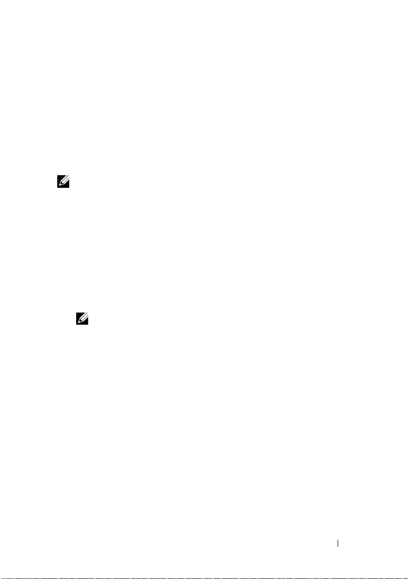
NOTE:
The illustrations in this document show cabling for only one PowerVault
MD3600i series storage array in a SAN environment. The illustrations also show only
the default IP addresses for the PowerVault MD3600i series storage array. To cable more
than one PowerVault MD3600i series storage array in a SAN environment,
see the Deployment Guide.
4
Getting Started With Your System
Page 7
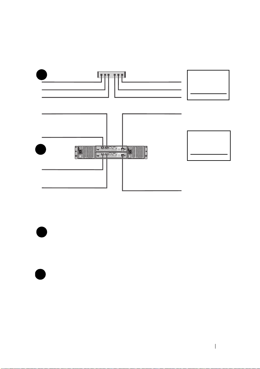
Completing the iSCSI Worksheet
Mutual
CHAP Secret
Ta rg et
CHAP Secret
A
B
host server
PowerVault MD3600i
series storage array
192.168.130.101 (In 0 default)
192.168.131.101 (In 1 default)
192.168.128.101 (management network port)
192.168.130.102 (In 0 default)
192.168.131.102 (In 1 default)
192.168.128.102 (management network port)
If you need additional space for more than one host server, use an additional sheet.
iSCSI port 0
iSCSI port 1
Management port
Subnet mask
Default gateway
A
___ . ___ . ___ . ___
___ . ___ . ___ . ___
___ . ___ . ___ . ___
___ . ___ . ___ . ___
___ . ___ . ___ . ___
___ . ___ . ___ . ___
___ . ___ . ___ . ___
___ . ___ . ___ . ___
___ . ___ . ___ . ___
Static IP address (storage array)
Subnet mask
Default gateway
B
___ . ___ . ___ . ___
___ . ___ . ___ . ___
___ . ___ . ___ . ___
___ . ___ . ___ . ___
___ . ___ . ___ . ___
___ . ___ . ___ . ___
iSCSI controller 0, In 0
iSCSI controller 0, In 1
Management port cntrl 0
iSCSI controller 1, In 0
iSCSI controller 1, In 1
Management port cntrl 1
___ . ___ . ___ . ___
___ . ___ . ___ . ___
___ . ___ . ___ . ___
___ . ___ . ___ . ___
___ . ___ . ___ . ___
___ . ___ . ___ . ___
___ . ___ . ___ . ___
___ . ___ . ___ . ___
___ . ___ . ___ . ___
___ . ___ . ___ . ___
___ . ___ . ___ . ___
___ . ___ . ___ . ___
Static IP address (host server)
NOTE:
Challenge Handshake Authentication Protocol (CHAP) is an optional iSCSI authentication
method where the storage array (target) authenticates iSCSI initiators on the host server. For more
information, see “Understanding CHAP Authentication” in the Deployment Guide.
IPv4 Settings
Getting Started With Your System
5
Page 8
NOTE:
For information about the IPv6 worksheet, see the Deployment Guide.
Other Documentation and Media You May Need
WARNING:
your system. Warranty information may be included within this document or
as a separate document.
NOTE:
support.dell.com/manuals.
• The rack documentation included with your rack solution describes how
to install your system into a rack.
•The
describes how to troubleshoot the system and install or replace system
components.
•The
configuring the software and hardware.
•The
interface (CLI) to configure and manage your storage array.
•The
installing the SMI-S provider.
• Any media that ships with your system that provides documentation
and tools for configuring and managing your system, including those
pertaining to the operating system, system management software,
system updates, and system components that you purchased
with your system.
See the safety and regulatory information that shipped with
All PowerVault MD3600i series storage array documents are available at
Owner’s Manual
Deployment Guide
CLI Guide
SMI-S Provider Installation Guide
provides information about system features and
provides information about installing and
provides information about using the command line
provides information about
NOTE:
Always check for updates on support.dell.com/manuals and read the
updates first because they often supersede information in other documents.
6
Getting Started With Your System
Page 9
Preparing the Host Server
Supported Operating Systems
• Microsoft Windows Server
• Red Hat Enterprise Linux
• SUSE Linux Enterprise Server
•VMware
NOTE:
For the latest information on all supported operating system versions,
see the Support Matrix at support.dell.com/manuals.
Additional NICs for iSCSI
When installing additional NICs, it is recommended that:
• You use dedicated redundant storage networks for iSCSI traffic.
If a dedicated network is not feasible, isolate the iSCSI traffic from
general network traffic using virtual local area networks (VLAN).
• You use additional NICs dedicated for iSCSI traffic.
• The NICs must be added in pairs for redundancy.
NOTE:
A single NIC is also supported.
NIC Configuration
In a SAN environment, depending on the number of switches, it is
recommended that you use two unique subnets for iSCSI traffic.
For direct-attached storage environments, each NIC directly connected to
the PowerVault MD36xxi must be on a separate subnet. All host IP addresses
must be configured before installing the MD storage software.
Getting Started With Your System
7
Page 10
Common Configurations
Up to 64 hosts
Server 1
Server 2
Storage array
Corporate, public,
or private network
Switch 1
Switch 2
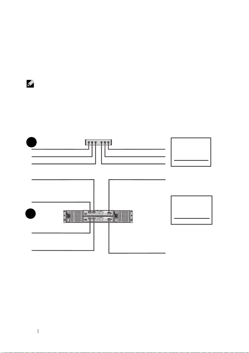
Cabling Your SAN-Attached Hosts
Connect all cables between the servers, switches, and storage arrays as shown
in the following illustration. For more examples of cabling the storage arrays,
see the Deployment Guide at support.dell.com/manuals.
8
Getting Started With Your System
Page 11
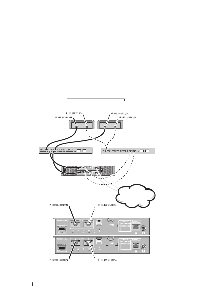
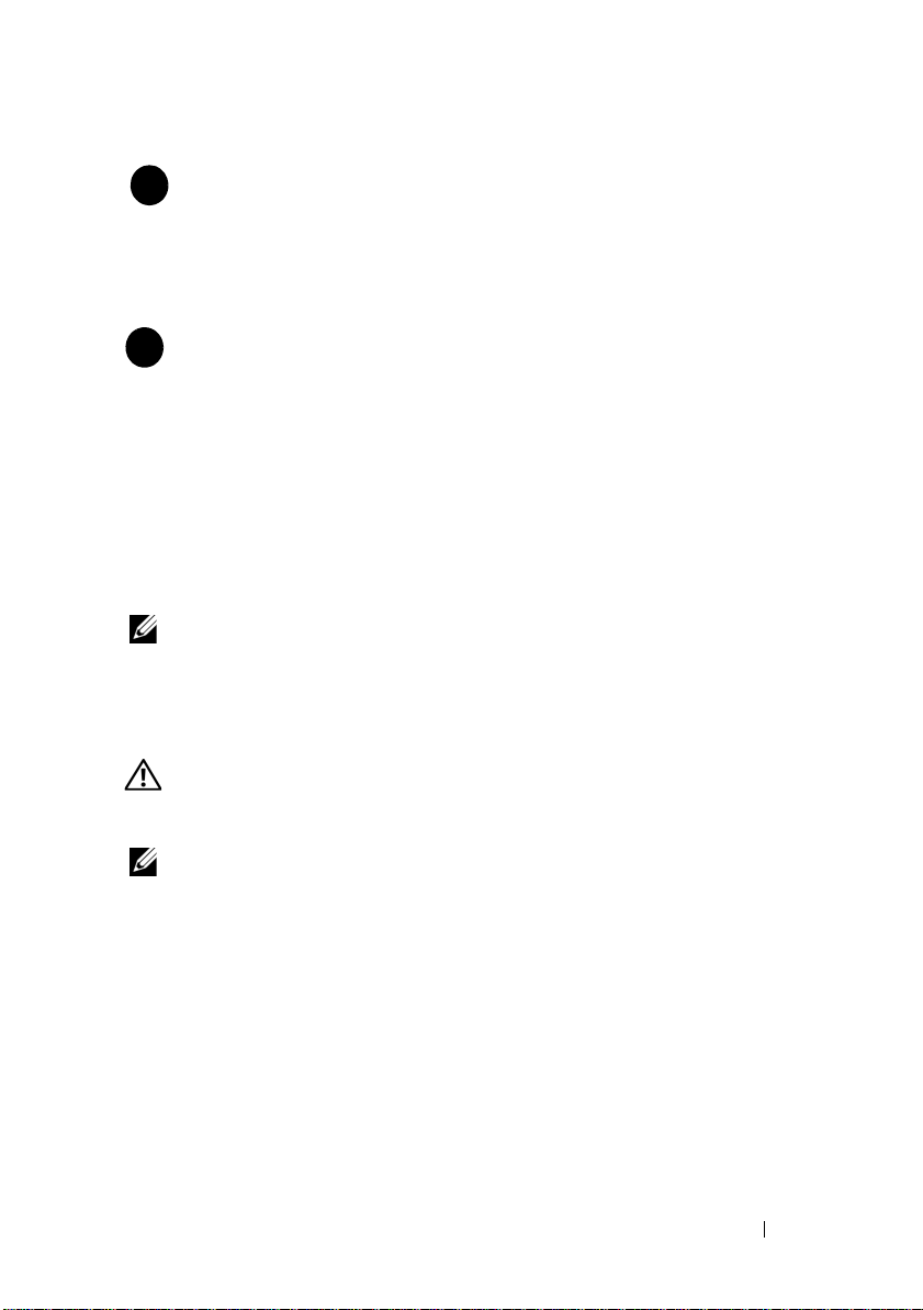
Cabling Your Direct-Attached Hosts
Server 1
Server 2
Storage array
Corporate, public,
or private network
Getting Started With Your System
9
Page 12
Installation and Configuration
WARNING:
instructions that came with the system.
Unpacking the System
Unpack your system and identify each item with the packing list that shipped
with your system.
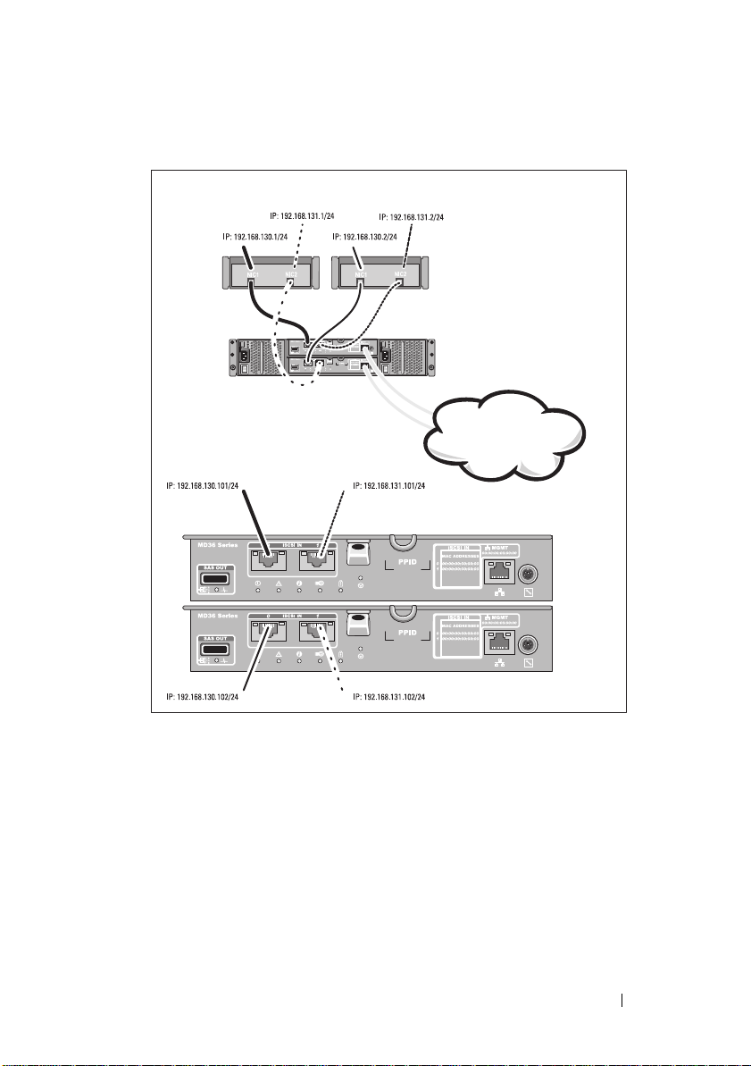
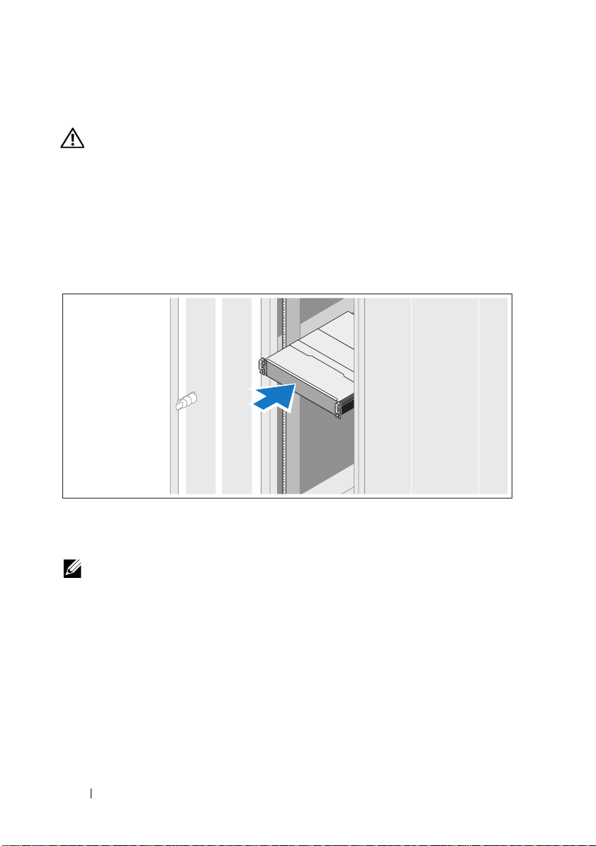
Installing the Rails and System in a Rack
Before performing the following procedure, review the safety
Assemble the rails and install the system in the rack following the safety
instructions and the rack installation instructions provided with your system.
NOTE:
To balance the weight load, it is recommended that you install the
PowerVault MD3600i series storage arrays at the bottom of the rack and the
PowerVault MD1200 series expansion enclosures above it.
10
Getting Started With Your System
Page 13
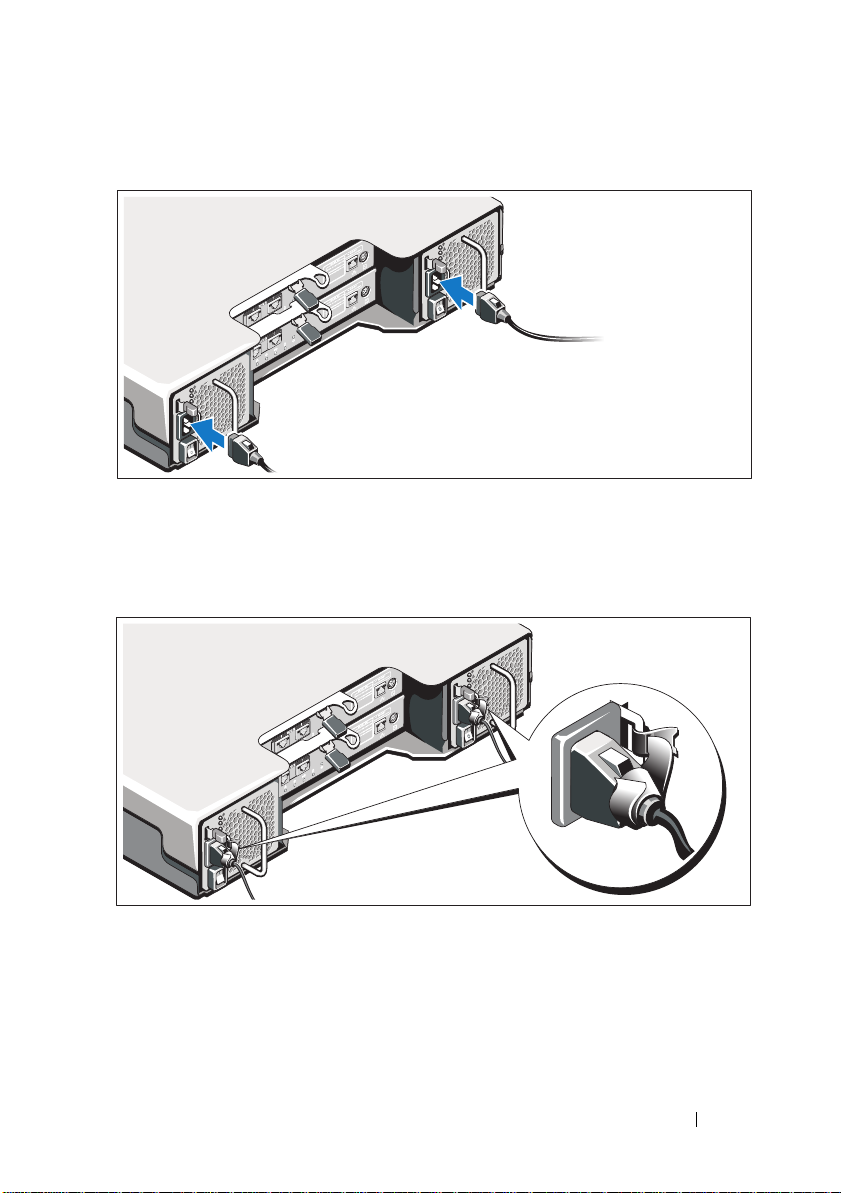
Connecting the Power Cable(s)
Ensure that the power switch is in the OFF position before connecting the
power cables. Connect the system’s power cable(s) to the system.
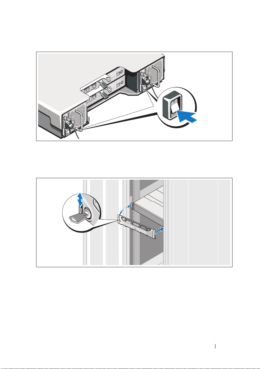
Securing the Power Cable(s)
Secure the cable(s) firmly to the bracket using the provided strap.
Plug the other end of the power cable(s) into a grounded electrical outlet or
a separate power source such as an uninterrupted power supply (UPS) or
a power distribution unit (PDU). Each power supply must be connected
to a separate power circuit.
Getting Started With Your System
11
Page 14

Cabling Your Expansion Enclosure
PowerVault MD3600i
series storage array
PowerVault MD1200
series expansion
enclosure 1 (optional)
PowerVault MD1200
series expansion
enclosure 2 (optional)
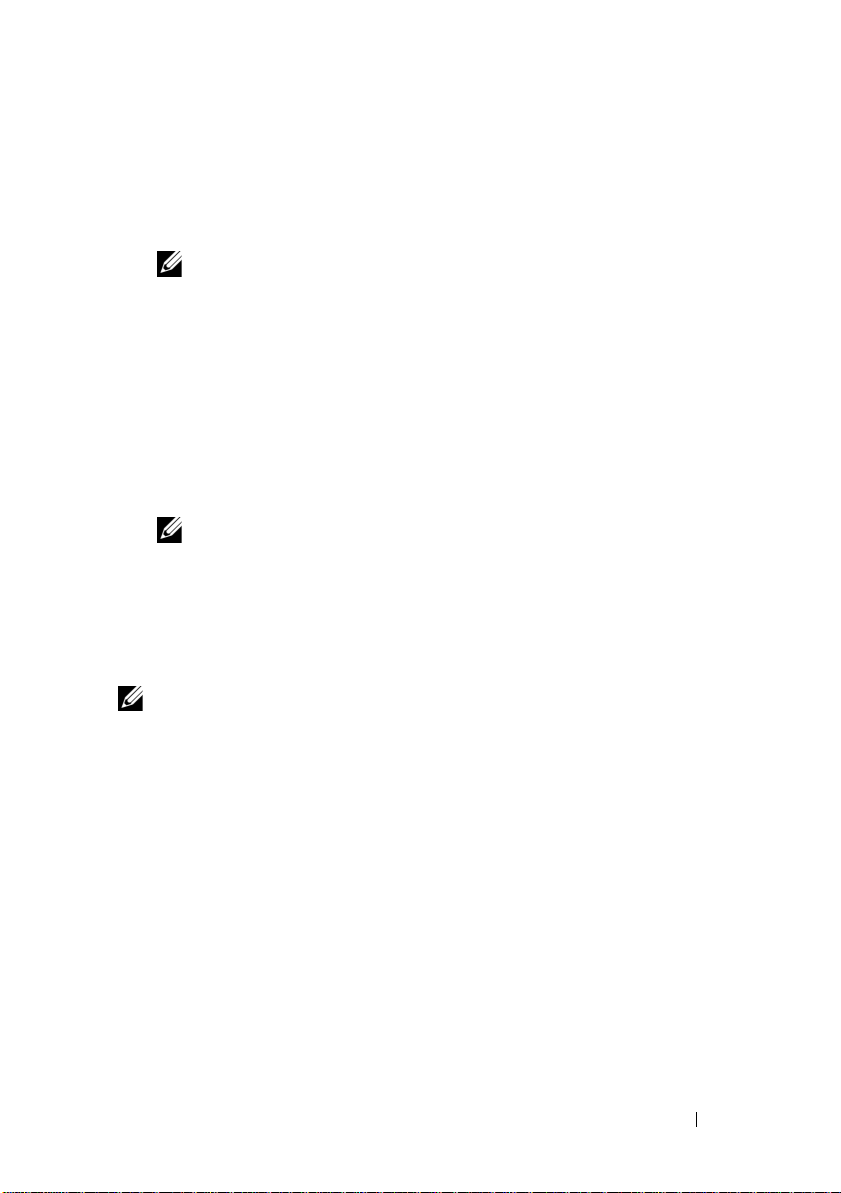
Turning On the Enclosure
Turn on components in the following order
1
Ethernet switches (if used)
2
PowerVault MD1200 series expansion enclosures (if used)
NOTE:
Before turning on the storage array, ensure that the expansion
enclosure status LED on the front of the enclosure is blue.
3
PowerVault MD3600i series storage array
12
NOTE:
Before turning on the host server(s), ensure that the storage array
status LED on the front of the storage array is blue.
Getting Started With Your System
Page 15
4
Host server(s)
Installing the Bezel
Install the bezel (optional).
Getting Started With Your System
13
Page 16

Installing the MD Storage Software
NOTE:
For detailed instructions about installing the MD storage software, setting
up the enclosure, and the post-installation tasks, see the Deployment Guide.
The MD Storage Manager software configures, manages and monitors the
storage array. The MD Configuration Utility (MDCU) is an optional utility
that provides a consolidated approach for configuring the management and
iSCSI host ports, and creating sessions for the iSCSI modular disk storage
arrays. It is recommended that you use MDCU to configure iSCSI on each
host server connected to the storage array. To install the MD storage software:
1
Insert the MD series resource media.
Depending on your operating system, the installer may launch
automatically. If the installer does not launch automatically, navigate to
the root directory of the installation media (or downloaded installer
image) and run the
navigate to the root of the resource media and run the
NOTE:
By default, the Red Hat Enterprise Linux operating system mounts the
resource media with the -noexec mount option which does not allow you to
run executable files. To change this setting, see the Readme file in the root
directory of the installation media.
2
Select
Install MD Storage Software
3
Read and accept the license agreement.
4
Select one of the following installation options from the
drop-down menu:
Full (recommended)
•
software, host-based storage agent, multipath driver, and hardware
providers.
•
Host Only
drivers.
•
Management
providers.
Custom
•
md_launcher.exe
file. For Linux-based systems,
autorun
file.
.
Install Set
—Installs the MD Storage Manager (client)
—Installs the host-based storage agent and multipath
—Installs the management software and hardware
—Allows you to select specific components.
14
Getting Started With Your System
Page 17
5
Select the MD storage array model(s) you are setting up to serve as data
storage for this host server.
6
Choose whether to start the event monitor service automatically when the
host server reboots or manually
NOTE:
This option is applicable only to Windows client software installation.
7
Confirm the installation location and click
8
If prompted, reboot the host server after the installation completes.
9
When the reboot is complete, the MDCU may launch automatically.
Install
.
If the MDCU does not launch automatically, launch it manually.
• In a Windows-based operating system, click
Disk Configuration Utility
.
Start→
• In a Linux-based operating system, double-click the
Configuration Utility
NOTE:
If MDCU is not installed, see the Deployment Guide at
support.dell.com/manuals.
10
Start the
11
If applicable, activate any premium features purchased with your storage
MD Storage Manager
icon on the desktop.
and discover the array(s).
Dell→
Modular
Modular Disk
array. If you purchased premium features, see the printed activation card
shipped with your storage array.
NOTE:
The MD Storage Manager installer automatically installs the required
drivers, firmware, and operating system patches/hotfixes to operate your storage
array. These drivers and firmware are also available at support.dell.com. In
addition, see the Support Matrix at support.dell.com/manuals for any additional
settings and/or software required for your specific storage array.
Getting Started With Your System
15
Page 18
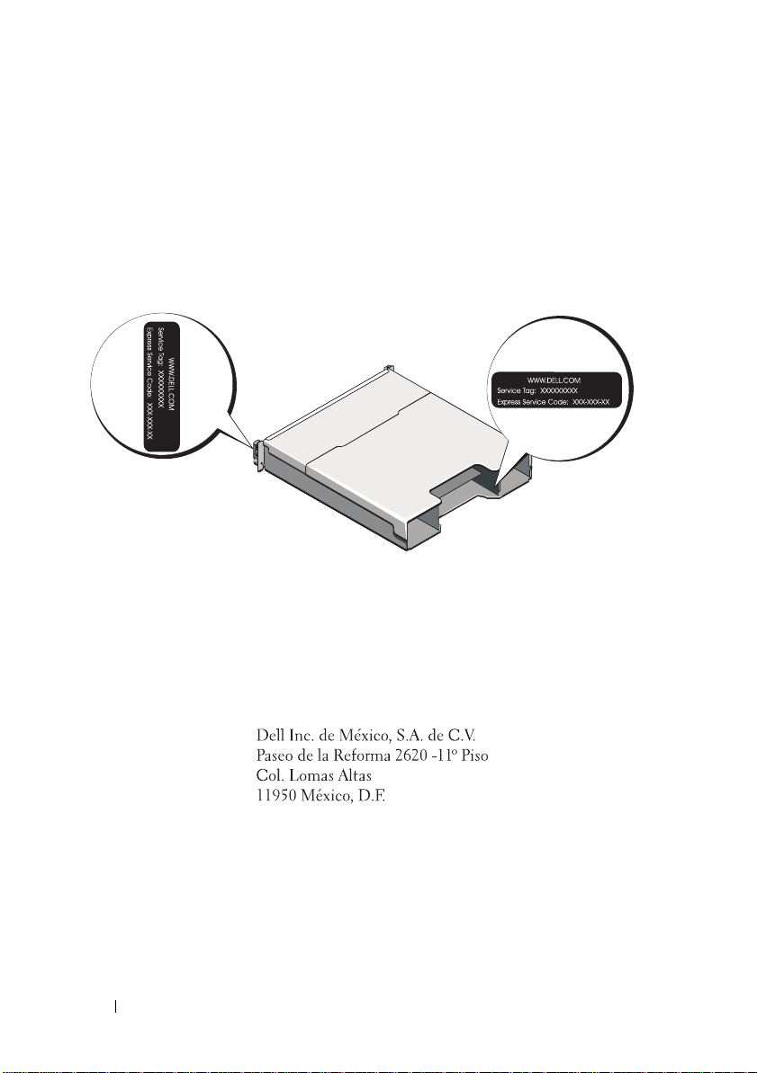
Locating Your Service Tag
Your system is identified by a unique Express Service Code and Service Tag
number. The Express Service Code and Service Tag are found on the front of
the system and at the back of the system next to the RAID controller
modules. This information is used by Dell to route support calls to the
appropriate personnel.
NOM Information (Mexico Only)
The following information is provided on the device described
in this document in compliance with the requirements of the
official Mexican standards (NOM):
Importer:
Model number: E03J and E04J
Supply voltage: 100–240 V CA
Frequency: 50/60 Hz
Current consumption: 8.6 A
16
Getting Started With Your System
Page 19

Technical Specifications
Drives
PowerVault MD3600i Up to twelve 3.5-inch SAS hot-swappable
hard drives (3.0 Gbps and 6.0 Gbps)
PowerVault MD3620i Up to twenty four 2.5-inch SAS
hot-swappable hard drives (3.0 Gbps and
6.0 Gbps)
RAID Controller Modules
RAID controller modules
Back-Panel Connectors (Per RAID Controller Module)
iSCSI connectors Two 10 GB iSCSI IN connectors to
SAS expansion connector One SAS OUT port for expansion to an
Serial connector One 6-pin mini-DIN connector
Management Ethernet connector One 100/1000 Base-T port Ethernet for
• One or two hot-swappable modules
with temperature sensors
• 2 GB of cache per controller
connect hosts
additional PowerVault MD1200 series
enclosure.
NOTE:
SAS connectors are SFF-8088 compliant.
NOTE:
For technical support use only.
out-of-band management of the enclosure
NOTE:
The default management port IP
addresses for the primary and secondary RAID
controller modules are 192.168.128.101 and
192.168.128.102, respectively. By default, the
management ports are set to Dynamic Host
Configuration Protocol (DHCP). If the controller
is unable to get an IP address configuration
from a DHCP server within a specified time out
period (approximately 3 minutes), it defaults
back to static IP addressing. For more
information, see the Deployment Guide.
Getting Started With Your System
17
Page 20

Expansion
PowerVault MD1200 series Supports a maximum of 192 hard drives with
any combination of PowerVault MD1200 or
PowerVault MD1220 expansion enclosures.
Support for 192 hard drives is a Premium
Feature and requires activation. The
maximum number of hard drives supported
without using the Premium Feature is 120.
Redundant path connectivity provides
redundant data paths to each hard drive.
Backplane Board
Connectors
Sensors Two temperature sensors
LED Indicators
Front panel
Hard-drive carrier
Power supply/cooling fan Three LED status indicators for power supply
• 12 or 24 SAS hard-drive connectors
• Two power supply/cooling fan
module connectors
• Two sets of RAID controller module
connectors
• One control panel connector for front LEDs
and enclosure mode switch
• One two-color LED indicator for
system status
• Two single-color LED indicators for power
and enclosure mode
NOTE:
The enclosure mode LED is not
applicable to the PowerVault MD3600i series
storage array.
• One single-color activity LED
• One two-color LED status indicator
per drive
status, power supply/fan fault, and AC status
18
Getting Started With Your System
Page 21

LED Indicators (continued)
RAID controller module Eight single-color LEDs:
• One battery fault
• One cache active
• One controller fault
• One controller power
• One system identification
• One management Ethernet activity
• Two iSCSI IN port activity
Four two-color LEDs:
• Two iSCSI IN link speed
• One SAS OUT link or fault
• One management Ethernet link speed
Switch
System identification button Located on the front control panel.
This button is used to locate a system
within a rack.
Enclosure mode switch Located on the front of the system.
This switch is not applicable to the
PowerVault MD3600i series storage array.
Password reset switch Located on the back panel of the RAID
controller module. This switch is used to
reset the storage array password.
Power Supplies
AC power supply (per power supply)
Wattage
Vo lt ag e
Heat dissipation
Maximum inrush current
600 W
100–240 VAC (8.6 A–4.3 A)
100 W
Under typical line conditions and over the
entire system ambient operating range,
the inrush current may reach a maximum of
55 A per power supply for 10 ms or less.
Getting Started With Your System
19
Page 22

Available Hard-Drive Power (Per Slot)
PowerVault MD3600i 25 W
PowerVault MD3620i 12 W
RAID Controller Module Power (Per Slot)
Maximum power consumption 100 W
Physical
PowerVault MD3600i
Height
Width
Depth
Weight (maximum configuration)
Weig h t ( em pt y)
PowerVault MD3620i
Height
Width
Depth
Weight (maximum configuration)
Weig h t ( em pt y)
8.68 cm (3.41 inches)
44.63 cm (17.57 inches)
60.20 cm (23.70 inches)
29.30 kg (64.6 lb)
8.84 kg (19.5 lb)
8.68 cm (3.41 inches)
44.63 cm (17.57 inches)
54.90 cm (21.61 inches)
24.2 kg (53.4 lb)
8.61 kg (19lb)
Environmental
NOTE:
For additional information about environmental measurements for specific
system configurations, see www.dell.com/environmental_datasheets.
Te mp e ra t u re
20
Operating
Getting Started With Your System
10 °C to 35 °C (50 °F to 95 °F) with a
maximum temperature gradation of 10 °C per
hour
NOTE:
For altitudes above 2950 feet, the
maximum operating temperature is derated
1ºF/550 ft.
Page 23

Environmental (continued)
Storage
Relative humidity
Operating
Storage
Maximum vibration
Operating
Storage
Maximum shock
Operating
Storage
Altitude
Operating
Storage
Airborne Contaminant Level
Class
–40° to 65°C (–40° to 149°F) with
a maximum temperature gradation
of 20°C per hour
20% to 80% (noncondensing) with
a maximum humidity gradation
of 10% per hour
5% to 95% (noncondensing)
0.25 G at 3–200 Hz for 15 min
0.5 G at 3–200 Hz for 15 min
One shock pulse in the positive z axis
(one pulse on each side of the system) of
31 G for 2.6 ms in the operational orientation
Six consecutively executed shock pulses
in the positive and negative x, y, and z axes
(one pulse on each side of the system)
of 71 G for up to 2 ms
–16 to 3048 m (–50 to 10,000 ft)
NOTE:
For altitudes above 2950 feet,
the maximum operating temperature
is derated 1ºF/550 ft.
–16 to 10,600 m (–50 to 35,000 ft)
G1 as defined by ISA-S71.04-1985
Getting Started With Your System
21
Page 24

22
Getting Started With Your System
Page 25

Disková pole
Dell PowerVault
MD3600i
a
MD3620i
Začínáme se systémem
Číslo modelu série: E03J a E04J
Page 26

Poznámky a upozornění
POZNÁMKA:
využití počítače.
UPOZORNĚNÍ:
ztráty dat v případě nedodržení pokynů.
POZNÁMKA označuje důležité informace, které pomáhají lepšímu
UPOZORNĚNÍ poukazuje na možnost poškození hardwaru nebo
VAROVÁNÍ:
VAROVÁNÍ upozorňuje na potenciální nebezpečí poškození majetku,
úrazu nebo smrti.
____________________
Informace v této publikaci se mohou bez předchozího upozornění změnit.
© 2011 Dell Inc. Všechna práva vyhrazena.
Jakákoli reprodukce těchto materiálů bez písemného povolení společnosti Dell Inc. je přísně zakázána.
Ochranné známky použité v tomto textu: Dell™, logo DELL a PowerVault™ jsou ochranné známky
společnosti Dell Inc. Microsoft
ochranné známky společnosti Microsoft Corporation ve Spojených státech anebo v jiných zemích.
®
Red Hat
ve Spojených státech a v jiných zemích. SUSE
Inc. v USA a dalších zemích. VMware
v USA anebo v dalších zemích.
Ostatní ochranné známky a obchodní názvy mohou být v této publikaci použity v souvislosti
s právními subjekty, které si na tyto ochranné známky a názvy svých produktů činí nárok. Společnost
Dell Inc. se zříká všech vlastnických nároků na ochranné známky a obchodní názvy jiné než vlastní.
a Red Hat Enterprise Linux® jsou registrované ochranné známky společnosti Red Hat, Inc.
®
a Windows Server® jsou bud’ ochranné známky, nebo registrované
®
je registrovaná ochranná známka společnosti Novell,
®
je registrovaná ochranná známka společnosti VMware, Inc.
Číslo modelu série: E03J a E04J
2011 - 08 P/N T1VCV Rev. A02
Page 27

Než začnete
POZNÁMKA:
MD3600i jak Dell PowerVault MD3600i, tak Dell PowerVault MD3620i. Název rozšiřující
skříň série Dell PowerVault MD1200 se vztahuje jak k Dell PowerVault MD1200, tak k
Dell PowerVault MD1220.
Než začnete s instalací diskového pole série Dell PowerVault MD3600i, vezměte
v úvahu osvědčené metody, s jejichž pomocí zajistíte, aby diskové pole pracovalo
s maximální účinností a nabízelo plnou redundanci (pokud je třeba).
• Diskové pole série PowerVault MD3600i je produkt založený na
technologii 10GBase-T a vyžaduje infrastrukturu schopnou pracovat s
technologií 10GBase-T skládající se z kabelů kategorie 6 nebo vyšších,
propojovacích panelů 10GBase-T a přepínačů.
• Existující infrastruktury 1GBase-T lze používat bud’ za pomocí přepínače
10GBase-T, který bude sít’ 10GBase-T připojovat, nebo za pomocí ruční
konfigurace portů iSCSI tak, aby pracovaly s rychlostmi 1GBase-T. Ke
konfiguraci rychlosti portů můžete též použít nástroj MDCU (Modular
Disk Configuration Utility). Více informací o nástroji MDCU naleznete v
části Instalace softwaru pro úložiště MD Storage na straně 35.
POZNÁMKA:
rychlost je nutno nastavit ručně.
• V celé síti používejte Ethernetové kabely kategorie 6 (nebo vyšší).
• Doporučujeme, abyste pro datové přenosy iSCSI používali dedikované
IP SAN. Zasílání řídicích dat lze oddělit do samostatné sítě určené k
tomuto účelu.
• Než začnete konfigurovat iSCSI, vyplňte příslušný konfigurační pracovní
list. Viz Vyplnění pracovního listu iSCSI na straně 26. Tento pracovní list
bude tvořit zdroj informací o fyzické síti.
• Poté co vyplníte pracovní list iSCSI, zakreslete si konfiguraci. Teprve poté
proved’te nastavení.
• Vždy nastavujte redundantní datové cesty iSCSI. Budou sloužit jako
náhradní cesty do/z hostitelského serveru v případě, že bude některá
z datových cest vyřazena z provozu.
• Pokud je na hostitelském serveru nainstalováno více sít’ových karet,
doporučujeme, abyste pro zasílání řídicích a obyčejných dat iSCSI
používali různé podsítě.
V tomto dokumentu označuje název diskové pole série Dell PowerVault
Automatické vyjednávání rychlosti není podporováno a pracovní
Začínáme se systémem
25
Page 28
• Než mezi hostitelským serverem a diskovým polem připojíte jakékoli
Tajemství
protokolu
CHAP - vzájemné
Cíl Tajemství
CHAP
A
B
hostitelský server
Disková pole série
PowerVault MD3600i
192.168.130.101
(standardně In 0)
192.168.131.101 (standardně In 1)
192.168.128.101 (port pro řízení sítě)
192.168.130.102
(standardně In 0)
192.168.131.102
(standardně In 1)
192.168.128.102
(port pro řízení sítě)
Potřebujete-li více místa pro více než jeden hostitelský server, použijte další list.
kabely, označte každý port a konektor.
• Pokud jsou sesít’ované systémy pod napětím, vždy dodržujte správné
postupy při zapínání a vypínání systémů. Musíte též zajistit, aby důležité
sít’ové komponenty měly oddělené hlavní obvody.
POZNÁMKA:
diskového pole série PowerVault MD3600i v prostředí SAN. Obrázky též zobrazují pouze
standardní IP adresy diskového pole série PowerVault MD3600i. Chcete-li připojit více než
jedno diskové pole série PowerVault MD3600i v prostředí SAN, viz
Obrázky obsažené v tomto dokumentu zobrazují připojení pouze jednoho
Instalační příručka
Vyplnění pracovního listu iSCSI
Nastavení IPv4
.
POZNÁMKA:
metoda iSCSI, kdy diskové pole (cíl) autentizuje iniciátory iSCSI na hostitelském serveru. Více informací
„Understanding CHAP Authentication“ (Autentizace CHAP) v
26
Začínáme se systémem
Protokol CHAP (Challenge Handshake Authentication Protocol) je volitelná autentizační
Instalační příručce
.
viz
Page 29
iSCSI port 0
iSCSI port 1
Řídicí port
Maska podsítě
Výchozí brána
A
___ . ___ . ___ . ___ .
___ . ___ . ___ . ___ .
___ . ___ . ___ . ___ .
___ . ___ . ___ . ___ .
___ . ___ . ___ . ___ .
___ . ___ . ___ . ___ .
___ . ___ . ___ . ___ .
___ . ___ . ___ . ___ .
___ . ___ . ___ . ___ .
Statická IP adresa (diskové pole)
Maska podsítě
Výchozí brána
B
___ . ___ . ___ . ___ .
___ . ___ . ___ . ___ .
___ . ___ . ___ . ___ .
___ . ___ . ___ . ___ .
___ . ___ . ___ . ___ .
___ . ___ . ___ . ___ .
Řadič iSCSI 0, In 0
Řadič iSCSI 0, In 1
Řídicí port cntrl 0
Řadič iSCSI 1, In 0
Řadič iSCSI 1, In 1
Řídicí port cntrl 1
___ . ___ . ___ . ___ .
___ . ___ . ___ . ___ .
___ . ___ . ___ . ___ .
___ . ___ . ___ . ___ .
___ . ___ . ___ . ___ .
___ . ___ . ___ . ___ .
___ . ___ . ___ . ___ .
___ . ___ . ___ . ___ .
___ . ___ . ___ . ___ .
___ . ___ . ___ . ___ .
___ . ___ . ___ . ___ .
___ . ___ . ___ . ___ .
Statická IP adresa (hostitelský server)
POZNÁMKA:
Informace o pracovním listě pro IPv6 viz
Instalační příručka
Další dokumenty a média, které můžete potřebovat
VAROVÁNÍ:
dodány se systémem. Informace o záruce jsou součástí tohoto dokumentu nebo
jsou přiloženy samostatně.
Prostudujte si informace o bezpečnosti a předpisech, které byly
.
POZNÁMKA:
na adrese
• Pokyny k instalaci do stojanu dodané se stojanovým řešením popisují
instalaci systému do stojanu.
•
Příručka majitele hardwaru
a popisuje řešení problémů se systémem a instalaci nebo výměnu
komponent.
•
Instalační příručka
a hardwaru.
•
Příručka CLI
diskového pole používat rozhraní CLI.
Veškeré dokumenty pro disková pole série PowerVault MD3600i lze získat
support.dell.com/manuals
obsahuje informace o tom, jak ke konfiguraci a správě
obsahuje informace o instalaci a konfiguraci softwaru
.
obsahuje informace o funkcích systému
Začínáme se systémem
27
Page 30
•
Instalační příručka poskytovatele SMI-S
obsahuje informace o instalaci
poskytovatele SMI-S.
• Média dodaná se systémem obsahují dokumentaci a nástroje pro
konfiguraci a správu systému. Mohou být dodána například média týkající
se operačního systému, softwaru pro správu systému, aktualizací systému a
komponent zakoupených se systémem.
POZNÁMKA:
support.dell.com/manuals
ostatních dokumentech.
Vždy nejprve zkontrolujte a pročtěte aktualizace uvedené na adrese
, protože tyto aktualizace často nahrazují informace v
Příprava hostitelského serveru
Podporované operační systémy
• Microsoft Windows Server
• Red Hat Enterprise Linux
• SUSE Linux Enterprise Server
•VMware
POZNÁMKA:
systémů naleznete v
Další sít’ové karty pro iSCSI
Chcete-li instalovat další sít’ové karty, doporučujeme abyste:
• pro provoz iSCSI používali dedikovanou redundantní SAN, pokud není
použití dedikované sítě možné, oddělili provoz iSCSI od zbytku provozu
v síti pomocí sítí VLAN.
• používali další sít’ové karty dedikované pro provoz iSCSI.
• Sít’ové karty je z důvodů redundance nutné vždy přidávat po dvojicích.
POZNÁMKA:
Nejnovější informace o všech podporovaných verzích operačních
matici odborné pomoci
Umístění jediné sít’ové karty je také podporováno.
na adrese
support.dell.com/manuals
.
Konfigurace sít’ových karet
V prostředí SAN doporučujeme, abyste pro provoz iSCSI používali dvě
jedinečné podsítě (dle počtu přepínačů). V prostředí s hostitelskými systémy
DAS musí být každá sít’ová karta, která je přímo připojená k systému
PowerVault MD36
je nutno nakonfigurovat ještě před instalací softwaru pro úložiště MD Storage.
28
Začínáme se systémem
xx
i, ve vlastní podsíti. IP adresy všech hostitelských systémů
Page 31

Obvyklé konfigurace
Až 64 hostitelských systémů
Server 1
Server 2
Diskové pole
Firemní, veřejná
nebo soukromá sít’
Přepínač 1
Přepínač 2
Připojení hostitelských systémů v SAN
Připojte všechny kabely mezi servery, přepínači a diskovými poli, jak je ukázáno
na následujícím obrázku. Více příkladů připojení diskových polí viz
příručka
na adrese
support.dell.com/manuals
.
Instalační
Začínáme se systémem
29
Page 32

Připojení hostitelských systémů v DAS
Server 1
Server 2
Diskové pole
Firemní, veřejná
nebo soukromá sít’
30
Začínáme se systémem
Page 33

Instalace a konfigurace
VAROVÁNÍ:
pokyny dodané se systémem.
Rozbalení systému
Rozbalte systém a zkontrolujte každou položku dle seznamu, který jste obdrželi
společně se systémem.
Instalace kolejniček a systému do stojanu
Před provedením následujícího postupu si prostudujte bezpečnostní
Sestavte kolejničky a nainstalujte systém do stojanu podle bezpečnostních
pokynů a pokynů k instalaci do stojanu dodaných se systémem.
POZNÁMKA:
série PowerVault MD3600i do spodní části stojanu a rozšiřující skříně série PowerVault
MD1200 nad něj.
Chcete-li správně vyvážit stojan, doporučujeme namontovat diskové pole
Začínáme se systémem
31
Page 34

Připojení napájecích kabelů
Předtím, než připojíte napájecí kabely, se prosím ujistěte, že se vypínač nachází
v poloze VYPNUTÝ. Připojte napájecí kabely k systému.
Zajištění napájecích kabelů
Pomocí řemínku pevně připevněte kabely k držáku.
Poté zasuňte druhé konce napájecích kabelů do uzemněné elektrické
zásuvky nebo je připojte k samostatnému zdroji napájení, například ke zdroji
nepřerušitelného napájení (UPS) nebo k jednotce rozvaděče (PDU). Každý zdroj
energie musí být připojen k vlastnímu hlavnímu obvodu.
32
Začínáme se systémem
Page 35

Připojení rozšiřující skříně
Disková pole série
PowerVault MD3600i
Rozšiřující skříň
PowerVault MD1200 1
(volitelné)
Rozšiřující skříň
PowerVault MD1200 2
(volitelné)
Zapnutí rozšiřující skříně
Zapněte komponenty v následujícím pořadí
1
Ethernetové přepínače (pokud se používají)
2
Rozšiřující skříně série PowerVault MD1200 (pokud se používají)
POZNÁMKA:
LED v přední části rozšiřující skříně svítí modře.
3
Disková pole série PowerVault MD3600i
Předtím, než zapnete diskové pole, ujistěte se, že stavová
POZNÁMKA:
LED v přední části diskového pole svítí modře.
Předtím, než zapnete hostitelské servery, ujistěte se, že stavová
Začínáme se systémem
33
Page 36

4
Hostitelské servery
Instalace čelního krytu
Nainstalujte čelní kryt (volitelný).
34
Začínáme se systémem
Page 37

Instalace softwaru pro úložiště MD Storage
POZNÁMKA:
skříně a úkolů, které je třeba vykonat po instalaci, viz
Aplikace MD Storage Manager slouží ke konfiguraci, správě a sledování
diskového pole. Nástroj MDCU (MD Configuration Utility) je volitelný
nástroj, který poskytuje jednotný přístup ke konfiguraci řídicích portů,
hostitelských portů iSCSI a k vytváření relací modulárních diskových polí
iSCSI. Doporučujeme, abyste nástroj MDCU používali ke konfiguraci iSCSI
na každém hostitelském serveru, který je k diskovému poli připojen. Chcete-li
nainstalovat software pro úložiště MD Storage:
1
Vložte zdrojové médium série MD.
V závislosti na vašem operačním systému se může automaticky spustit
instalační program. Pokud se instalační program automaticky nespustí,
přejděte do kořenového adresáře instalačního média (nebo staženého
obrazu instalačního programu) a spust’te soubor md_launcher.exe.
U systémů Linux přejděte do kořenového adresáře zdrojového média a
spust’te soubor autorun.
POZNÁMKA:
zdrojové médium za použití
spustitelné soubory. Chcete-li toto nastavení změnit, nahlédněte do souboru
Readme v kořenovém adresáři instalačního média.
2
Zvolte možnost
úložiště MD).
3
Přečtěte si licenční smlouvu a přijměte ji.
4
V nabídce
možností instalace:
Full (Kompletní) (doporučené)
•
Storage Manager (klient), hostitelského agenta, ovladače vícecestných
disků a poskytovatele hardwaru.
•
Host Only (Lokální)
ovladače vícecestných disků.
Management (Správa)
•
poskytovatele hardwaru.
•
Custom (Vlastní)
Podrobné pokyny k instalaci softwaru pro úložiště MD storage, nastavení
Operační systém Red Hat Enterprise Linux standardně připojuje
možnosti –noexec
Install MD Storage Software
Install Set
(Instalační balík) vyberte jednu z následujících
Instalační příručka
, která neumožňuje spouštět
(Instalovat software pro
.
- umožňuje instalaci programu MD
- umožňuje instalaci hostitelského agenta a
- umožňuje instalaci softwaru pro správu a
- umožňuje vybrat konkrétní komponenty.
Začínáme se systémem
35
Page 38

5
Vyberte modely diskových polí MD, které mají sloužit jako datová úložiště
tohoto hostitelského serveru.
6
Vyberte, zda se má po restartu hostitelského serveru spustit služba
sledování událostí automaticky nebo manuálně.
POZNÁMKA:
systému Windows.
7
Potvrd’te umístění instalace a klepněte na
8
Jakmile o to budete po dokončení instalace požádáni, restartujte
Tato možnost je platná pouze pro instalace klientského softwaru
Install
(Instalace).
hostitelský server.
9
Po dokončení restartu může dojít k automatickému spuštění MDCU.
Pokud se MDCU automaticky nespustí, spust’te jej manuálně.
• V operačním systému Windows klepněte na
Disk Configuration Utility
(Start→ Dell→ Nástroj konfigurace
Start→
Dell→
modulárních disků).
• V operačním systému Linux poklepejte na ikonu
Configuration Utility
(Nástroj konfigurace modulárních disků)
Modular Disk
na ploše.
POZNÁMKA:
příručky
10
Spust’te správce
11
Pokud je třeba, aktivujte veškeré dodatečné funkce zakoupené s diskovým
Pokud není nástroj MDCU nainstalován, nahlédněte do
na adrese
support.dell.com/manuals
MD Storage Manager
.
a vyhledejte disková pole.
polem. Pokud jste si zakoupili dodatečné funkce, použijte tištěnou
aktivační kartu dodanou s diskovým polem.
Modular
Instalační
POZNÁMKA:
ovladače, firmware a opravy/hotfixy operačního systému potřebné pro práci s diskovým
polem. Tyto ovladače a firmware lze též získat na adrese
informace o nastavení anebo softwaru potřebném pro konkrétní diskové pole naleznete
Matici odborné pomoci
v
36
Začínáme se systémem
Instalátor programu
na adrese support.dell.com/manuals
MD Storage Manager
support.dell.com
automaticky nainstaluje
.
. Další
Page 39

Vyhledání servisního označení
Váš systém je identifikován jedinečným kódem expresní služby a číslem
servisního označení. Kód expresní služby a servisní označení lze nalézt na přední
straně systému a na zadní straně systému vedle modulů řadičů RAID. Tyto
informace používá společnost Dell k nasměrování žádostí o odbornou pomoc
příslušným zaměstnancům.
Informace NOM (jen pro Mexiko)
K zařízení popsanému v tomto dokumentu se vztahují v souladu s požadavky
oficiální mexické normy NOM následující informace:
Dovozce:
Číslo modelu: E03J a E04J
Napájecí napětí: 100–240 V stř.
Frekvence: 50/60 Hz
Spotřeba proudu: 8,6 A
Začínáme se systémem
37
Page 40

Technické specifikace
Jednotky
PowerVault MD3600i Až dvanáct 3,5palcových pevných disků
SAS, které lze vyměňovat za chodu
(3,0 Gb/s a 6,0 Gb/s)
PowerVault MD3620i Až dvacet čtyři 2,5palcových pevných
disků SAS, které lze vyměňovat za chodu
(3,0 Gb/s a 6,0 Gb/s)
Moduly řadičů RAID
Moduly řadičů RAID
Konektory na zadním panelu (na jeden modul řadiče RAID)
Konektory iSCSI Dva konektory 10 GB iSCSI IN k připojení
Rozšiřující konektor SAS Jeden výstupní port SAS OUT k rozšíření o
Konektor sériového rozhraní Jeden 6kolíkový konektor mini-DIN.
Konektor Ethernetu pro řízení Jeden port pro Ethernet typu 100/1000 Base-T
• Jeden nebo dva moduly s tepelnými čidly,
které lze vyměňovat za chodu
• 2 GB vyrovnávací paměti na řadič
hostitelských systémů
další skříň série PowerVault MD1200
POZNÁMKA:
POZNÁMKA:
pomoci.
pro vzdálenou správu skříně
POZNÁMKA:
primárního a sekundárního modulu řadiče RAID
jsou 192.168.128.101 a 192.168.128.102.
Řídicí porty jsou standardně nastaveny na práci
s protokolem DHCP. Pokud řadič není schopen
získat od serveru DHCP konfiguraci IP adresy
ve stanoveném časovém limitu (přibližně 3
minuty), standardně se přepne na používání
statické IP adresy. Další informace získáte
v
Instalační příručce
Konektory SAS vyhovují SFF-8088.
Pouze pro zaměstnance odborné
Výchozí IP adresy řídicích portů
.
38
Začínáme se systémem
Page 41

Rozšíření
Série PowerVault MD1200 Podporuje maximálně 192 pevných disků s
jakoukoli kombinací rozšiřujících skříní
PowerVault MD1200 či PowerVault MD1220.
Podpora 192 pevných disků je dodatečná
funkce a vyžaduje aktivaci. Maximální počet
podporovaných pevných disků bez použití
této dodatečné funkce je 120
Redundantní konektivita cest poskytuje
redundantní datové cesty pro každý pevný disk
Zadní deska
Konektory
Senzory Dva senzory teploty
Indikátory LED
Čelní panel
Nosič pevných disků
• 12 nebo 24 konektorů pro pevné disky SAS
• Dva konektory pro napájecí zdroje/moduly
s chladicími ventilátory
• Dvě sady konektorů pro moduly
řadičů RAID
• Jeden konektor ovládacího panelu pro
čelní indikátory LED a přepínač
svazkových režimů
• Jeden dvoubarevný indikátor LED pro
stav systému
• Dva jednobarevné indikátory LED pro
napájení a režim pro použití ve skříni
POZNÁMKA:
se nenachází na diskových polích série PowerVault
MD3600i.
• Jeden jednobarevný indikátor LED
pro aktivitu
• Jeden dvoubarevný indikátor LED pro stav
každého disku
Indikátor LED pro režim ve skříni
Začínáme se systémem
39
Page 42

Indikátory LED (pokračování)
Napájecí zdroj/chladicí ventilátor Tři indikátory LED pro stav napájecího
zdroje, selhání napájecího zdroje nebo
ventilátoru a stav napájení střídavým
proudem
Modul řadiče RAID Osm jednobarevných indikátorů LED:
• Jeden pro závadu baterie
• Jeden pro aktivní vyrovnávací pamět’
• Jeden pro závadu řadiče
• Jeden pro napájení řadiče
• Jeden pro identifikaci systému
• Jeden pro aktivitu Ethernetu pro řízení
• Dva pro aktivitu portů iSCSI IN
Čtyři dvoubarevné indikátory LED:
• Dva pro rychlost připojení iSCSI IN
• Jeden pro připojení nebo závady SAS OUT
• Jeden pro rychlost připojení Ethernetu
pro řízení
Přepínač
Tlačítko pro identifikaci systému Umístěno na předním řídicím panelu.
Toto tlačítko slouží k nalezení systému
uvnitř stojanu
Přepínač režimu pro použití ve skříni Umístěný na přední straně systému. Tento
přepínač se nenachází v diskovém poli série
PowerVault MD3600i
Tlačítko pro vymazání hesla Umístěno na zadní straně modulu řadiče
RAID. Toto tlačítko se používá k resetování
hesla diskových polí
Dodávky energie
Střídavý proud (na jeden napájecí zdroj)
Výkon
Napětí
40
Začínáme se systémem
600 W
100 – 240 V stř. (8,6 A – 4,3 A)
Page 43

Dodávky energie (pokračování)
Odvod tepla
Maximální nárazový proud V typických podmínkách napájení a v celém
Dostupné napájení pevných disků (na zdířku)
PowerVault MD3600i 25 W
PowerVault MD3620i 12 W
Napájení modulu řadiče RAID (na zdířku)
Maximální spotřeba energie 100 W
Rozměry
PowerVault MD3600i
Výška
Šířka
Hloubka
Hmotnost (maximální konfigurace)
Hmotnost (prázdné)
PowerVault MD3620i
Výška
Šířka
Hloubka
Hmotnost (maximální konfigurace)
Hmotnost (prázdné)
100 W
provozním rozsahu systému může nárazový
proud dosáhnout 55 A na jeden napájecí zdroj
po dobu 10 ms nebo méně
8,68 cm (3,41 palců)
44,63 cm (17,57 palců)
60,20 cm (23,70 palců)
29,30 kg (64,6 lb)
8,84 kg (19,5 lb)
8,68 cm (3,41 palců)
44,63 cm (17,57 palců)
54,90 cm (21,61 palců)
24,2 kg (53,4 lb)
8,61 kg (19 lb)
Začínáme se systémem
41
Page 44

Prostředí
POZNÁMKA:
systémové konfigurace na adrese
Te pl o ta
Provozní
Skladovací
Relativní vlhkost
Provozní
Skladovací
Maximální vibrace
Provozní
Skladovací
Maximální ráz
Provozní
Skladovací
Nadmořská výška
Provozní
Skladovací
Úroveň znečištění vzduchu
Třída
Další informace o měřených údajích prostředí najdete pro jednotlivé
www.dell.com/environmental_datasheets
10 až 35 °C s maximálním nárůstem teploty o
10 °C za hodinu
POZNÁMKA:
900 metrů je maximální provozní teplota snížena
o 0,6 °C na každých 167 metrů.
-40 až 65 °C s maximálním nárůstem teploty
o 20 °C za hodinu
20 až 80 % (bez kondenzace) s maximálním
nárůstem vlhkosti o 10 % za hodinu
5 až 95 % (bez kondenzace)
0,25 G při 3–200 Hz po dobu 15 minut
0,5 G při 3–200 Hz po dobu 15 minut
Jeden rázový impuls v kladné ose z (jeden
impuls na každé straně systému) o síle 31 G
v délce do 2,6 ms v provozní orientaci
Šest po sobě jdoucích rázových impulsů v
kladné i záporné ose x, y a z (jeden impuls
na každé straně systému) o síle 71 G v délce
do 2 ms
-16 až 3 048 m
POZNÁMKA:
metrů je maximální provozní teplota snížena o
0,6 °C na každých 167 metrů.
-16 až 10 600 m
G1 dle normy ISA-S71.04-1985
V nadmořských výškách nad
V nadmořských výškách nad 900
.
42
Začínáme se systémem
Page 45

Matrices de stockage
Dell PowerVault MD3600i
et MD3620i
Mise en route
Séries de modèle réglementaire E03J et E04J
Page 46

Remarques, précautions et avertissements
REMARQUE :
vous aider à mieux utiliser votre ordinateur.
une REMARQUE indique des informations importantes qui peuvent
PRÉCAUTION :
une PRÉCAUTION vous avertit d'un risque d'endommagement du
matériel ou de perte de données en cas de non-respect des instructions.
AVERTISSEMENT:
un AVERTISSEMENT vous avertit d’un risque
d'endommagement du matériel, de blessure corporelle ou même de mort.
____________________
Les informations que contient ce document sont sujettes à modification sans préavis.
© 2011 Dell Inc. Tous droits réservés.
La reproduction de ce document, de quelque manière que ce soit, sans l'autorisation écrite de Dell Inc.
est strictement interdite.
Marques utilisées dans ce document : Dell™, le logo DELL et PowerVault™ sont des marques de
Dell Inc. Microsoft
Corporation aux États-Unis et/ou dans d'autres pays. Red Hat
marques déposées de Red Hat, Inc. aux États-Unis et dans d'autres pays. SUSE
déposée de Novell, Inc. aux États-Unis et dans d'autres pays. VMware
VMware, Inc. aux États-Unis et/ou dans d'autres juridictions.
D'autres marques et noms commerciaux peuvent être utilisés dans ce document pour faire référence
aux entités revendiquant la propriété de ces marques ou de ces noms de produits. Dell Inc. rejette tout
intérêt exclusif dans les marques et les noms commerciaux autres que les siens.
®
et Windows Server® sont des marques ou des marques déposées de Microsoft
®
et Red Hat Enterprise Linux® sont des
®
®
est une marque
est une marque déposée de
Séries de modèle réglementaire E03J et E04J
2011 - 08 N/P T1VCV Rév. A02
Page 47

Avant de commencer
REMARQUE :
PowerVault série MD3600i concernent les matrices de stockage Dell PowerVault
MD3600i et Dell PowerVault MD3620i. Les références au boîtier d'extension
Dell PowerVault série MD1200 concernent les matrices de stockage Dell
PowerVault MD1200 et Dell PowerVault MD1220.
Avant d'installer votre matrice de stockage Dell PowerVault série MD3600i,
vous devez considérer certaines pratiques d'excellence pour assurer le
fonctionnement le plus efficace possible de votre matrice de stockage et une
redondance complète (si nécessaire).
• La matrice de stockage PowerVault MD3600i est un produit 10GBase-T
exigeant une infrastructure compatible 10GBase-T constituée de câbles de
catégorie 6 ou supérieure, des tableaux de connexions compatibles
10GBase-T et des commutateurs.
• Les infrastructures 1GBase-T existantes peuvent être utilisées à l'aide d'un
commutateur 10GBase-T, qui interconnecte le réseau 10GBase-T, ou en
configurant manuellement les ports iSCSI sur des vitesses 1GBase-T. Vous
pouvez également utiliser l'utilitaire de configuration de disques
modulaires (MDCU) pour configurer la vitesse des ports. Pour plus
d'informations sur le MDCU, voir « Installation du logiciel MD Storage »,
à la page 56.
REMARQUE :
fonctionnement doit être configurée manuellement.
• Utilisez toujours un câble Ethernet de catégorie 6 (ou supérieure) à travers le
réseau.
• Il vous est recommandé d'utiliser un IP SAN dédié pour la transmission
des données iSCSI. La gestion de trafic peut être isolée sur un réseau de
gestion distinct.
• Renseignez la liste de vérification de configuration de l'interface iSCSI
avant de configurer iSCSI. Voir « Renseigner la liste de vérification de
l'interface iSCSI », à la page 47. Cette liste permet de regrouper les
informations de réseaux physiques en un seul endroit.
• Esquissez la configuration après avoir renseigné la liste de vérification
iSCSI et avant de définir la solution.
• Configurez toujours des chemins d'accès aux données iSCSI redondants
de manière à fournir différents chemins d'accès allant au serveur hôte et en
sortant, dans l'éventualité d'une défaillance de l'un d'eux.
dans ce document, les références à la matrice de stockage Dell
l'auto-négociation n'est pas prise en charge et la vitesse de
Guide de mise en route
45
Page 48

• Si plusieurs cartes réseau sont installées sur un hôte, il vous est
recommandé d'utiliser plusieurs sous-réseaux pour la gestion et les liaisons
de données iSCSI.
• Avant de connecter tout câble entre le serveur hôte et la matrice de
stockage, étiquetez physiquement chaque port et chaque connecteur.
• Suivez toujours les procédures de mise sous et hors tension lors des cycles
d'alimentation du réseau. Vous devez également vous assurer que les
composants essentiels du réseau se trouvent sur différents circuits
d'alimentation.
REMARQUE :
câblage d'une matrice de stockage PowerVault MD3600i dans un environnement de
réseau SAN. Elles ne montrent également que les adresses IP par défaut de la matrice
de stockage PowerVault MD3600i. Pour câbler plus d'une matrice de stockage
PowerVault MD3600i dans un environnement de réseau SAN, voir le Guide de
déploiement.
les illustrations qui figurent dans ce document montrent uniquement le
46
Guide de mise en route
Page 49

Renseigner la liste de vérification de l'interface iSCSI
Clé secrète
CHAP mutuelle
Secret CHAP
Cible
A
B
serveur hôte
Matrice de stockage
PowerVault série
MD3600i
192.168.130.101 (ent. 0 par défaut)
192.168.131.101 (ent. 1 par défaut)
192.168.128.101 (port du réseau de gestion)
192.168.130.102 (ent. 0 par défaut)
192.168.131.102 (ent. 1 par défaut)
192.168.128.102 (port réseau de gestion)
Au besoin, utilisez une feuille supplémentaire (si vous disposez de plusieurs serveurs hôtes, par exemple).
Port iSCSI 0
Port iSCSI 1
Port de gestion
Masque de sous-réseau
Passerelle par défaut
A
___ ___ ___ ___
___ ___ ___ ___
___ ___ ___ ___
___ ___ ___ ___
___ ___ ___ ___
___ ___ ___ ___
___ ___ ___ ___
___ ___ ___ ___
___ ___ ___ ___
Adresse IP statique (m. de stockage)
Masque de sous-réseau
Passerelle par défaut
B
___ ___ ___ ___
___ ___ ___ ___
___ ___ ___ ___
___ ___ ___ ___
___ ___ ___ ___
___ ___ ___ ___
Contrôleur iSCSI 0, Ent. 0
Contrôleur iSCSI 0, Ent. 1
Port de gestion cntrl 0
Contrôleur iSCSI 1, Ent. 0
Contrôleur iSCSI 1, Ent. 1
Port de gestion cntrl 1
___ ___ ___ ___
___ ___ ___ ___
___ ___ ___ ___
___ ___ ___ ___
___ ___ ___ ___
___ ___ ___ ___
___ ___ ___ ___
___ ___ ___ ___
___ ___ ___ ___
___ ___ ___ ___
___ ___ ___ ___
___ ___ ___ ___
Adresse IP statique (serveur hôte)
REMARQUE :
CHAP (Challenge Handshake Authentication Protocol) est une méthode
d'authentification iSCSI facultative par laquelle la matrice de stockage (cible) authentifie les
initiateurs iSCSI du serveur hôte. Pour en savoir plus sur l'authentification CHAP, voir « Comprendre
l'authentification CHAP » dans le Guide de déploiement.
Paramètres IPv4
Guide de mise en route
47
Page 50

REMARQUE :
de déploiement.
pour plus d'informations sur la liste de vérification IPv6, voir le Guide
Autre documentation et support dont vous pourriez avoir besoin
AVERTISSEMENT:
réglementations qui accompagnent votre système. Les informations sur la garantie
se trouvent dans ce document ou dans un document distinct.
reportez-vous aux informations sur la sécurité et les
REMARQUE :
le site support.dell.com/manuals.
tous les documents PowerVault série MD3600i sont disponibles sur
• La documentation fournie avec le rack indique comment installer le
système dans un rack.
•Le
Manuel du propriétaire
contient des informations sur les
caractéristiques du système, ainsi que des instructions relatives au
dépannage et à l'installation ou au remplacement de composants.
•Le
Guide de déploiement
fournit des informations sur l'installation et la
configuration du logiciel et du matériel.
•Le
Guide CLI
fournit des informations sur l'utilisation de l'interface de
ligne de commande (CLI) pour configurer et gérer votre matrice de
stockage.
•Le
Guide d'installation de l'opérateur SMI-S
procure des informations sur
l'installation de l'opérateur SMI-S.
• Tous les supports fournis avec le système contiennent de la documentation
et des outils de configuration et de gestion du système, notamment du
système d'exploitation même et du logiciel de gestion du système ; les
supports contiennent également des mises à jour et les composants
système que vous avez achetés avec le système.
REMARQUE :
support.dell.com/manuals et lisez-les en premier, car elles remplacent souvent les
informations que contiennent les autres documents.
vérifiez toujours si des mises à jour sont disponibles sur le site
48
Guide de mise en route
Page 51

Préparation du serveur hôte
Systèmes d'exploitation pris en charge
• Microsoft Windows Server
• Red Hat Enterprise Linux
• SUSE Linux Enterprise Server
•VMware
REMARQUE :
systèmes d'exploitation prises en charge, reportez-vous à la Matrice de support sur
support.dell.com/manuals.
Cartes réseau supplémentaires pour l'interface iSCSI
Lors de l'installation de cartes réseau supplémentaires, il vous est
recommandé de :
• Utiliser des réseaux de stockage redondants dédiés pour le trafic iSCSI.
Isoler le trafic iSCSI du trafic de réseau général à l'aide du réseau local
virtuel (VLAN) si un réseau dédié n'est pas disponible.
• Utiliser des cartes réseau dédiées supplémentaires pour le trafic iSCSI.
• Les cartes réseau doivent être ajoutées par paires pour la redondance.
REMARQUE :
pour les informations les plus récentes sur toutes les versions de
une carte réseau seule est également prise en charge.
Configuration de carte réseau
Dans un environnement de réseau SAN, selon le nombre de commutateurs, il
vous est recommandé d'utiliser deux sous-réseaux uniques pour le trafic
iSCSI. Pour des environnements de stockage reliés directement, chaque carte
réseau en connexion directe avec la matrice de stockage MD36xxi doit se
trouver sur un sous-réseau différent. Toutes les adresses IP des hôtes doivent
être configurées avant l'installation du logiciel de stockage MD.
Guide de mise en route
49
Page 52

Configurations courantes
Jusqu'à 64 hôtes
Serveur 1
Serveur 2
Matrice de stockage
Réseau d'entreprise,
public ou privé
Commutateur 1
Commutateur 2
Câblage des hôtes reliés au réseau SAN
Connectez tous les câbles entre les serveurs, les commutateurs et les matrices
de stockage comme illustré ci-après. Pour davantage d'exemples de câblage
des matrices de stockage, voir le Guide de déploiement sur
support.dell.com/manuals.
50
Guide de mise en route
Page 53

Câblage des hôtes reliés directement
Serveur 1
Serveur 2
Matrice de
stockage
Réseau d'entreprise,
public ou privé
Guide de mise en route
51
Page 54

Installation et configuration
AVERTISSEMENT:
consignes de sécurité fournies avec le système.
Déballage du système
Déballez votre système et identifiez chaque élément en consultant la liste de
composants livrée avec votre système.
Installation des rails et du système dans un rack
avant d'exécuter la procédure ci-dessous, lisez les
Assemblez les rails et installez le système dans le rack en suivant les consignes
de sécurité et les instructions d'installation du rack fournies avec votre
système.
REMARQUE :
PowerVault série MD3600i en bas du rack et les boîtiers d'extension PowerVault
MD1200 au-dessus.
52
Guide de mise en route
pour équilibrer la charge, nous vous recommandons d'installer le
Page 55

Branchement du ou des câbles d'alimentation
Avant de connecter les câbles d'alimentation, assurez-vous que le
commutateur d'alimentation est en position OFF (ÉTEINT). Branchez le ou
les câbles d'alimentation sur le système.
Fixation du ou des câbles d'alimentation
Fixez fermement les câbles au support de fixation à l'aide de la lanière
fournie.
Guide de mise en route
53
Page 56

Branchez ensuite l'autre extrémité du ou des câbles sur une prise de courant
Matrice de stockage
PowerVault série
MD3600i
Boîtier d'extension
PowerVault série
MD1200 1 (en option)
Boîtier d'extension
PowerVault série
MD1200 2 (en option)
mise à la terre ou sur une source d'alimentation autonome (onduleur (UPS)
ou unité de distribution de l'alimentation (PDU)). Chaque bloc
d'alimentation doit être connecté à un circuit d'alimentation séparé.
Câblage de votre boîtier d'extension
Mise sous tension du boîtier
Mettez les composants sous tension dans l'ordre suivant
1
Commutateurs Ethernet (si utilisés)
2
Boîtiers d'extension PowerVault série MD1200 (si utilisés)
3
Matrice de stockage PowerVault série MD3600i
54
REMARQUE :
voyant d'état du boîtier d'extension à l'avant du boîtier est bleu.
REMARQUE :
voyant d'état de la matrice de stockage à l'avant de la matrice est bleu.
Guide de mise en route
avant d'allumer la matrice de stockage, assurez-vous que le
avant d'allumer le(s) serveur(s) hôte(s), assurez-vous que le
Page 57

4
Serveur(s) hôte
Installation du cadre
Installez le cadre (en option).
Guide de mise en route
55
Page 58

Installation du logiciel MD Storage
REMARQUE :
de stockage MD, la configuration du boîtier et les tâches après installation,
reportez-vous au Guide de déploiement.
L'application MD Storage Manager configure, gère, et contrôle la matrice de
stockage. L'utilitaire de configuration MD (MDCU) est un utilitaire
optionnel qui permet une approche consolidée de la configuration des ports
de gestion, des ports hôtes iSCSI et de la création de sessions pour les
matrices de stockage sur disques modulaires iSCSI. Il vous est recommandé
d'utiliser l'utilitaire MDCU pour configurer iSCSI sur chaque hôte connecté à
la matrice de stockage. Pour installer le logiciel de stockage MD :
1
Insérez le support Ressource série MD.
En fonction de votre système d'exploitation, l'installateur se lancera peut-
être automatiquement. Si l'installateur ne se lance pas automatiquement,
naviguez dans le répertoire racine du support d'installation (ou téléchargez
l'image d'installateur) et exécutez le fichier
systèmes exécutant Linux, naviguez vers la racine du support Ressource et
exécutez le fichier
REMARQUE :
Ressource à l'aide de l'option de montage
permet pas d'exécuter les fichiers exécutables. Pour modifier ce paramètre,
consultez le fichier
2
Sélectionnez
stockage MD).
3
Lisez le contrat de licence et acceptez-le.
4
Sélectionnez une des options d'installation suivantes dans le menu
déroulant
•
Full (recommended)
(client) MD Storage Manager, l'agent de stockage hôte, le pilote
multivoies et les fournisseurs de matériel.
•
Host Only
pilotes multivoies.
•
Management
fournisseurs de matériel.
•
Custom
spécifiques.
pour des instructions détaillées concernant l'installation du logiciel
autorun
par défaut, Red Hat Enterprise Linux (RHEL) monte le support
(Exécution auto).
Lisez-moi
dans le répertoire racine du support d'installation.
Install MD Storage Software
Install Set
(Configuration d'installation) :
md_launcher.exe
–noexec mount
(Installer le logiciel de
. Pour les
, ce qui ne vous
(Complète - recommandée) : installe le logiciel
(Hôte uniquement) : installe l'agent de stockage hôte et les
(Gestion) : installe le logiciel de gestion et les
(Personnalisée) : permet de sélectionner des composants
56
Guide de mise en route
Page 59

5
Sélectionnez le(s) modèle(s) de matrice de stockage MD que vous
souhaitez définir comme stockage de données pour ce serveur hôte.
6
Choisissez de démarrer le service de moniteur des événements
automatiquement lors du redémarrage du serveur hôte ou manuellement
REMARQUE :
Windows.
7
Confirmez l'emplacement de l'installation et cliquez sur
8
À l'invitation (le cas échéant), redémarrez le serveur hôte, une fois
cette option ne s'applique qu'à l'installation du logiciel client
Install
(Installer).
l'installation terminée.
9
Lorsque le redémarrage est terminé, l'utilitaire MDCU peut se lancer
automatiquement. S'il ne se lance pas automatiquement, lancez-le
manuellement.
• Dans un système d'exploitation Windows, cliquez sur
Dell→
Modular Disk Configuration Utility
(Utilitaire de
Démarrer→
configuration de disques modulaires).
• Dans un système d'exploitation Linux, double-cliquez sur l'icône
Modular Disk Configuration Utility
(Utilitaire de configuration de
disques modulaires) sur le bureau.
REMARQUE :
déploiement à l'adresse support.dell.com/manuals.
10
Démarrez
11
Le cas échéant, activez les fonctions premium achetées avec votre matrice
MD Storage Manager
si l'utilitaire MDCU n'est pas installé, voir le Guide de
et lancez la détection des matrices.
de stockage. Si vous avez acheté des fonctions premium, consultez la carte
d'activation livrée avec votre matrice de stockage.
REMARQUE :
pilotes, micrologiciel, et correctifs de système d'exploitation nécessaires pour le
fonctionnement de votre matrice de stockage. Ces pilotes et micrologiciels sont
également disponibles à l'adresse support.dell.com. Consultez également la
Matrice de support à l'adresse support.dell.com/manuals pour trouver des
paramètres et/ou logiciels supplémentaires requis pour votre matrice de stockage
spécifique.
l'installateur MD Storage Manager installe automatiquement les
Guide de mise en route
57
Page 60

Identification du numéro de service
Votre système est identifié par un code de service express et un numéro de
service uniques. Le code de service express et le numéro de service se trouvent
sur le devant et l'arrière du système à côté des modules de contrôleur RAID.
Dell utilise ces informations pour acheminer les appels de support au
technicien qui convient.
Informations NOM (Mexique uniquement)
Les informations suivantes sur l'appareil décrit dans ce document sont
fournies conformément aux exigences de la Norme Officielle Mexicaine
(NOM) :
Importateur :
Numéro de modèle : E03J et E04J
Tension d'alimentation : 100 à 240 V CA
Fréquence : 50/60 Hz
Consommation électrique : 8,6 A
58
Guide de mise en route
Page 61

Caractéristiques techniques
Lecteurs
PowerVault MD3600i Jusqu'à 12 disques durs SAS remplaçables à
chaud 3,5 pouces (3,0 Gb/s et 6,0 Gb/s)
PowerVault MD3620i Jusqu'à 24 disques durs SAS remplaçables à
chaud 2,5 pouces (3,0 Gb/s et 6,0 Gb/s)
Modules de contrôleur RAID
Les modules de contrôleur RAID
Connecteurs du panneau arrière (par module de contrôleur RAID)
Connecteurs iSCSI Deux connecteurs d'entrée iSCSI de 1 Go
Connecteur d'extension SAS Un port de sortie SAS pour l'extension à un
Connecteur série Un connecteur mini-DIN à 6 broches
• Un ou deux modules remplaçables à chaud
avec capteurs de température.
• 2 Go de mémoire cache par contrôleur
pour connecter les hôtes
boîtier PowerVault série MD1200
supplémentaire.
REMARQUE :
conformes SFF-8088.
REMARQUE :
personnel de maintenance.
les connecteurs SAS sont
cette option est réservée au
Guide de mise en route
59
Page 62

Connecteurs du panneau arrière (par module de contrôleur RAID) (suite)
Connecteur Ethernet de gestion Un port Ethernet 100/1000 Base-T pour une
gestion hors bande du boîtier
REMARQUE :
gestion par défaut pour les modules de
contrôleur RAID primaire et secondaire sont
respectivement192.168.128.101 et
192.168.128.102. Par défaut, les ports de gestion
sont définis sur le protocole DHCP (Dynamic
Host Configuration). Si le contrôleur ne parvient
pas à obtenir une configuration d'adresse IP
d'un serveur DHCP dans une période de temps
spécifiée (environ 3 minutes), il utilise
l'adressage IP statique par défaut. Pour plus
d'informations, voir le Guide de déploiement.
Extension
PowerVault Série MD1200 Prend en charge jusqu'à 192 disques durs avec
n'importe quelle combinaison de boîtiers
d'extension PowerVault MD1200 ou
PowerVault MD1220. La prise en charge de
192 disques durs est une fonction premium et
doit être activée. Le nombre maximum de
disques durs pris en charge lorsque la
fonction premium n'est pas utilisée est 120.
La connectivité à chemin redondant fournit
des chemins de données redondants à chaque
disque dur.
les adresses IP de port de
Carte de fond de panier
Connecteurs
Capteurs Deux capteurs de température
60
Guide de mise en route
• 12 ou 24 connecteurs de disque dur SAS
• Deux connecteurs pour les modules de
ventilation/alimentation
• Deux ensembles de connecteurs de module
de contrôleur RAID
• Un connecteur de panneau de commande
pour les voyants frontaux et le commutateur
de mode boîtier
Page 63

Voyants
Panneau avant
Support de disque dur
Bloc d'alimentation/ventilateur de
refroidissement
Module de contrôleur RAID Huit voyants monochromes :
• Un voyant bichrome indiquant l'état du
système
• Deux voyants monochromes (alimentation
et mode boîtier)
REMARQUE :
s'applique pas à la matrice de stockage
PowerVault série MD3600i.
• Un voyant d'activité monochrome
• Un voyant d'état bichrome par lecteur
Trois voyants d'état (état du bloc
d'alimentation, panne du bloc
d'alimentation/Ventilateur et état de
l'alimentation)
• Un voyant de panne de batterie
• Un voyant d'activité de la mémoire cache
• Un voyant de panne du contrôleur
• Un voyant d'état de l'alimentation de
contrôleur
• Un voyant système
• Un voyant d'activité de gestion Ethernet
• Deux voyants d'activité de port d'entrée
iSCSI
Quatre voyants bichromes :
• Deux voyants de vitesse de lien d'entrée
iSCSI
• Un voyant de panne ou de lien de sortie SAS
• Un voyant de vitesse de lien Ethernet de
gestion
le voyant du mode boîtier ne
Guide de mise en route
61
Page 64

Commutateur
Bouton d'identification du système Situé sur le panneau de commande avant. Ce
bouton sert à localiser un système au sein
d'un rack.
Sélecteur de mode du boîtier Situé sur le devant du système. Ce sélecteur
ne s'applique pas à la matrice de stockage
PowerVault MD3600i.
Sélecteur de réinitialisation du mot de
passe
Blocs d'alimentation
Alimentation secteur (par bloc d'alimentation)
Puissance
Te ns i on
Dissipation thermique
Courant d'appel maximal
Situé sur le panneau arrière du module de
contrôleur RAID. Ce sélecteur permet de
réinitialiser le mot de passe de la matrice de
stockage.
600 W
100–240 VCA (8,6 A–4,3 A)
100 W
Dans des conditions de ligne typiques et dans
toute la gamme ambiante de fonctionnement
du système, l'appel de courant peut atteindre
55 A par bloc d'alimentation pendant un
maximum de 10 ms.
Alimentation disponible pour les disques durs (par logement)
PowerVault MD3600i 25 W
PowerVault MD3620i 12 W
Alimentation du module de contrôleur RAID (par emplacement)
Consommation de courant maximale 100 W
62
Guide de mise en route
Page 65

Caractéristiques physiques
PowerVault MD3600i
Hauteur
Largeur
Profondeur
Poids (configuration maximale)
Poids (vide)
PowerVault MD3620i
Hauteur
Largeur
Profondeur
Poids (configuration maximale)
Poids (vide)
Environnement
REMARQUE :
environnementales liées aux différentes configurations du système, voir
www.dell.com/environmental_datasheets.
Température
En fonctionnement De 10 à 35 °C (50 à 95 °F) avec un gradient
Entreposage
Humidité relative
En fonctionnement
Entreposage
pour des informations supplémentaires sur les mesures
8,68 cm (3,41 pouces)
44,63 cm (17,57 pouces)
60,20 cm (23,70 pouces)
29,30 kg (64,6 livres)
8,84 kg (19,5 livres)
8,68 cm (3,41 pouces)
44,63 cm (17,57 pouces)
54,90 cm (21,61 pouces)
24,2 kg (53,4 livres)
8,61 kg (19 livres)
thermique maximal de 10 °C par heure
REMARQUE :
900 mètres (2 950 pieds), la température
maximale de fonctionnement est réduite de
0,55 °C (1 °F) tous les 168 mètres (550 pieds).
De -40 à 65 °C (-40 à 149 °F) avec un gradient
thermique maximal de 20 °C par heure
De 20 à 80 % (sans condensation) avec un
gradient d'humidité maximal de 10 % par
heure
De 5 à 95 % (sans condensation)
à des altitudes supérieures à
Guide de mise en route
63
Page 66

Environnement (suite)
Tolérance maximale aux vibrations
En fonctionnement
Entreposage
Choc maximal
En fonctionnement
Entreposage
Altitude
En fonctionnement
Entreposage
Contaminants en suspension dans l'air
Classe
0,25 G avec un balayage de 3 à 200 Hz
pendant 15 minutes
0,5 G avec un balayage de 3 à 200 Hz pendant
15 minutes
Une impulsion de choc de 31 G pendant un
maximum de 2,6 ms sur l'axe z positif (une
impulsion de chaque côté du système)
Six chocs consécutifs de 71 G pendant un
maximum de 2 ms en positif et négatif sur les
axes x, y et z (une impulsion de chaque côté
du système)
De -16 à 3 048 m (-50 à 10 000 pieds)
REMARQUE :
900 mètres (2 950 pieds), la température
maximale de fonctionnement est réduite de
0,55 °C (1 °F) tous les 168 mètres (550 pieds).
De -16 à 10 600 m (-50 à 35 000 pieds)
G1 selon la norme ISA-S71.04-1985
à des altitudes supérieures à
64
Guide de mise en route
Page 67

Dell PowerVault MD3600i- und
MD3620i-Speicher-Arrays
Handbuch zum Einstieg
Vorschriftenmodell Serie E03J und E04J
Page 68

Anmerkungen, Vorsichtshinweise und
Warnhinweise
ANMERKUNG:
sam, mit denen Sie den Computer besser einsetzen können.
Eine ANMERKUNG macht auf wichtige Informationen aufmerk-
VORSICHTSHINWEIS:
Ein VORSICHTSHINWEIS macht darauf aufmerksam, dass
bei Nichtbefolgung von Anweisungen eine mögliche Beschädigung der Hardware
oder ein Verlust von Daten droht.
WARNUNG:
Durch eine WARNUNG werden Sie auf Gefahrenquellen hingewiesen, die materielle Schäden, Verletzungen oder sogar den Tod von Personen zur
Folge haben können.
____________________
Irrtümer und technische Änderungen vorbehalten.
© 2011 Dell Inc. Alle Rechte vorbehalten.
Die V ervielfältigung oder Wiedergabe dieser Materialien in je glicher Weise ohne v orherige schriftliche
Genehmigung von Dell Inc. ist strengstens untersagt.
In diesem Text verwendete Marken: Dell™, das DELL Logo und PowerVault™ sind Marken von
Dell Inc. Microsoft
Microsoft Corporation in den USA und/oder anderen Ländern; Red Hat
®
sind eingetragene Marken von Red Hat, Inc. in den USA und anderen Ländern. SUSE® ist
Linux
eine eingetragene Marke von Novell, Inc. in den USA und anderen Ländern. VMware
eingetragene Marke von VMware, Inc. in den USA und/oder anderen Gerichtsbarkeiten.
Alle anderen in dieser Publikation möglicherweise verwendeten Marken und Handelsbezeichnungen
beziehen sich entweder auf die entsprechenden Hersteller und Firmen oder auf deren Produkte.
Dell Inc. erhebt keinen Anspruch auf Markenzeichen und Handelsbezeichnungen mit Ausnahme der
eigenen.
®
und Windows Server® sind entweder Marken oder eingetragene Marken der
®
und Red Hat Enterprise
®
ist eine
Vorschriftenmodell Serie E03J und E04J
2011 - 08 P/N T1VCV Rev. A02
Page 69

Bevor Sie beginnen
ANMERKUNG:
„Dell PowerVault Speicher-Array der Reihe MD3600i“ auf sowohl Dell PowerVault
MD3600i als auch auf Dell PowerVault MD3620i. Das Erweiterungsgehäuse für Dell
PowerVault der Reihe MD1200 bezieht sich sowohl auf Dell PowerVault MD1200 als
auch auf Dell PowerVault MD1220.
Bevor Sie Ihr Dell PowerVault Speicher-Array der Reihe MD3600i einrichten,
sollten Sie einige bewährte Verfahren beachten, um sicherzustellen, dass Ihr
Speicher-Gehäuse bei maximaler Effizienz arbeitet und, soweit zutreffend,
eine vollständige Redundanz bietet.
• Das PowerVault Speicher-Array der MD3600i-Reihe ist ein 10GBase-T
Produkt, das eine 10GBase-T-fähige Infrastruktur erfordert, die aus Kabeln
der Kategorie 6 oder höher, 10GBase-T-fähigen Patchpanels und Switches
besteht.
• Vorhandene 1GBase-T-Infrastrukturen können entweder durch einen
10GBase-T-Switch, der das 10GBase-T-Netzwerk verbindet, oder durch
manuelle Konfigurierung der iSCSI-Ports verwendet werden, um mit einer
1GBase-T-Geschwindigkeit ausgeführt zu werden. Sie können auch das
Hilfsprogramm Modular Disk Configuration Utility (MDCU) benutzen,
um die Portgeschwindigkeiten zu konfigurieren. Weitere Informationen zu
MDCU finden Sie unter „Installieren der MD-Storage-Software“ auf
Seite 78.
ANMERKUNG:
Betriebsgeschwindigkeit muss manuell konfiguriert werden.
• Verwenden Sie für das gesamte Netzwerk Ethernet-Kabel der Kategorie
6 (oder höher).
• Es wird empfohlen, ein dediziertes IP-SAN-Netzwerk für die iSCSIDatenübertragung zu verwenden. Der Verwaltungsdatenverkehr kann auf
einem separaten Verwaltungsnetzwerk isoliert werden.
• Füllen Sie vor der iSCSI-Konfiguration das iSCSI-Konfigurationsarbeitsblatt aus. Siehe „Ausfüllen des iSCSI-Arbeitsblatts“ auf Seite 69. Dieses
Arbeitsblatt fasst physikalische Netzwerkinformationen in einer einzigen
Quelle zusammen.
• Zeichnen Sie nach dem Ausfüllen des iSCSI-Arbeitsblatts die Konfiguration auf, bevor Sie die Lösung umsetzen.
In der vorliegenden Dokumentation bezieht sich der Ausdruck
Automatische Verhandlung wird nicht unterstützt und die
Handbuch zum Einstieg mit dem System
67
Page 70

• Für den Fall eines Datenpfadausfalls sollten Sie stets redundante iSCSIDatenpfade vorsehen, die als alternative Pfade zum und vom Host-Server
verwendet werden können.
• Falls mehrere Netzwerkschnittstellen-Controller (NICs) auf einem Host
installiert sind, wird empfohlen, für die Verwaltung und die iSCSIDatenverbindungen unterschiedliche Teilnetzwerke zu verwenden.
• Bevor Sie Kabel zwischen dem Host-Server und dem Speicher-Array
anschließen, sollten Sie alle Ports und Stecker physikalisch kennzeichnen.
• Beachten Sie stets die Vorschriften für das ordnungsgemäße Ein- und
Ausschalten, wenn Sie das Netzwerk mit Strom versorgen. Stellen Sie
außerdem sicher, dass kritische Netzwerkkomponenten an separate
Stromkreise angeschlossen sind.
ANMERKUNG:
einem PowerVault Speicher-Array der Reihe MD3600i in einer SAN-Umgebung. Die
Abbildungen zeigen außerdem nur die Standard-IP-Adressen für das PowerVault
Speicher-Array der Reihe MD3600i. Informationen zum Verkabeln mehrerer PowerVault
Speicher-Arrays der Reihe MD3600i in einer SAN-Umgebung finden Sie im Bereitstel-
lungshandbuch.
Die Abbildungen in diesem Dokument zeigen die Verkabelung von nur
68
Handbuch zum Einstieg mit dem System
Page 71

Ausfüllen des iSCSI-Arbeitsblatts
gem. CHAPGeheimschl.
Ziel CHAPGeheimschlüssel
A
B
Hostserver
PowerVault SpeicherArray der Reihe MD3600i
192.168.130.101 (Vorg.: Eing. 0)
192.168.131.101 (Vorg.: Eing. 1)
192.168.128.101 (Verw.-Netzwerkport)
192.168.130.102 (Vorg.: Eing. 0)
192.168.131.102 (Vorg.: Eing. 1)
192.168.128.102 (Verw.-Netzwerkport)
Wenn Sie zusätzlichen Platz für weitere Hostserver benötigen, verwenden Sie ein weiteres Arbeitsblatt.
iSCSI-Port 0
iSCSI-Port 1
Verwaltungs
schnittstelle
Subnetzmaske
Standard-
A
___ . ___ . ___ . ___
___ . ___ . ___ . ___
___ . ___ . ___ . ___
___ . ___ . ___ . ___
___ . ___ . ___ . ___
___ . ___ . ___ . ___
___ . ___ . ___ . ___
___ . ___ . ___ . ___
___ . ___ . ___ . ___
Feste IP-Adresse (Speicher-Array)
Subnetzmaske
Standard-
B
___ . ___ . ___ . ___
___ . ___ . ___ . ___
___ . ___ . ___ . ___
___ . ___ . ___ . ___
___ . ___ . ___ . ___
___ . ___ . ___ . ___
iSCSI-Controller 0, Eing. 0
i
SCSI-Controller 0, Eing. 1
Verwaltungsport-Contrl. 0
iSCSI-Controller 1, Eing. 0
iSCSI-Controller 1, Eing. 1
Verwaltungsport-Contrl. 1
___ . ___ . ___ . ___
___ . ___ . ___ . ___
___ . ___ . ___ . ___
___ . ___ . ___ . ___
___ . ___ . ___ . ___
___ . ___ . ___ . ___
___ . ___ . ___ . ___
___ . ___ . ___ . ___
___ . ___ . ___ . ___
___ . ___ . ___ . ___
___ . ___ . ___ . ___
___ . ___ . ___ . ___
Feste IP-Adresse (Hostserver)
ANMERKUNG:
CHAP (Challenge Handshake Authentication Protocol) ist ein optionales iSCSI-
Authentifizierungsverfahren, bei dem das Speicherarray (Target) iSCSI-Initiatoren am Hostserver
authentifiziert. Weitere Informationen finden Sie im Einrichtungshandbuch unter „Informationen zur
CHAP-Authentifizierung“.
IPv4-Einstellungen
Handbuch zum Einstieg mit dem System
69
Page 72

ANMERKUNG:
Bereitstellungshandbuch.
Weitere Informationen zum IPv6-Arbeitsblatt finden Sie im
Sonstige hilfreiche Dokumentationen und Medien
WARNUNG:
dem Computer geliefert wurden. Garantiebestimmungen können möglicherweise
als separates Dokument beigelegt sein.
Beachten Sie die Sicherheits- und Betriebsbestimmungen, die mit
ANMERKUNG:
MD3600i sind unter support.dell.com/manuals verfügbar.
Sämtliche Dokumente zum PowerVault Speicher-Array der Reihe
• In der zusammen mit der Rack-Lösung gelieferten Rack-Dokumentation
ist beschrieben, wie das System in einem Rack installiert wird.
•Im
Hardware-Benutzerhandbuch
erhalten Sie Informationen über Systemfunktionen, zur Fehlerbehebung am System und zum Installieren oder
Austauschen von Systemkomponenten.
•Im
Bereitstellungshandbuch
erhalten Sie Informationen zum Installieren
und Konfigurieren der Software und Hardware.
•Im
CLI-Handbuch
erhalten Sie Informationen zum Verwalten und
Konfigurieren Ihres Speicher-Arrays über die Befehlszeilenschnittstelle
(CLI).
•Im
SMI-S-Handbuch für Programmierer
erhalten Sie Informationen zum
Installieren des SMI-S-Anbieters.
• Alle im Lieferumfang des Systems enthaltenen Medien mit Dokumentationen und Hilfsmitteln zur Konfiguration und Verwaltung des Systems,
insbesondere in Bezug auf Betriebssystem, Systemverwaltungssoftware,
System-Updates und mit dem System erworbene Komponenten.
ANMERKUNG:
Dokumente vorliegen, lesen Sie diese immer zuerst, denn frühere Informationen
werden damit gegebenenfalls ungültig.
Wenn auf der Website support.dell.com/manuals aktualisierte
70
Handbuch zum Einstieg mit dem System
Page 73

Vorbereiten des Host-Servers
Unterstützte Betriebssysteme
• Microsoft Windows Server
• Red Hat Enterprise Linux
• SUSE Linux Enterprise Server
•VMware
ANMERKUNG:
versionen finden Sie in der Matrix der unterstützten Systeme unter
support.dell.com/manuals.
Zusätzliche NICs für iSCSI
Für die Installation zusätzlicher NICs gelten folgende Empfehlungen:
• Verwenden Sie dedizierte, redundante Speichernetzwerke für den iSCSIDatenverkehr. Falls kein dediziertes Netzwerk realisierbar ist, isolieren Sie
den iSCSI-Datenverkehr vom allgemeinen Netzwerkverkehr, indem Sie
virtuelle lokale Netzwerke (VLANs) verwenden.
• Verwenden Sie für den iSCSI-Datenverkehr zusätzliche dedizierte NICs.
• Die NICs müssen zur Sicherstellung der Redundanz paarweise hinzugefügt werden.
ANMERKUNG:
Aktuelle Informationen zu den unterstützten Betriebssystem-
Ein einziger NIC wird ebenfalls unterstützt.
NIC-Konfiguration
In einer SAN-Umgebung empfiehlt sich, je nach Anzahl der Switches, die
Verwendung von zwei eindeutigen Teilnetzwerken für den iSCSI-Datenverkehr. In Umgebungen mit direkt verbundenen Speichergeräten muss sich
jeder NIC, der direkt mit dem PowerVault MD36xxi verbunden ist, auf einem
separaten Teilnetzwerk befinden. Alle Host-IP-Addressen müssen vor der
Installation der MD-Storage-Software konfiguriert werden.
Handbuch zum Einstieg mit dem System
71
Page 74

Allgemeine Konfigurationen
Bis zu 64 Hosts
Server 1
Server 2
Speicher-Array
Firmen-,
öffentliches oder
privates
Netzwerk
Schalter 1
Switch 2
Verkabeln der über ein SAN-Netzwerk angeschlossenen Hosts
Verbinden Sie alle Kabel zwischen den Servern, Switches und SpeicherArrays, wie in der folgenden Abbildung dargestellt. Weitere Beispiele zur
Verkabelung der Speicher-Arrays finden Sie im Bereitstellungshandbuch unter
support.dell.com/manuals.
72
Handbuch zum Einstieg mit dem System
Page 75

Verkabeln der direkt angeschlossenen Hosts
Server 1
Server 2
Speicher-Array
Firmen-, öffentliches
oder privates
Netzwerk
Handbuch zum Einstieg mit dem System
73
Page 76

Installation und Konfiguration
WARNUNG:
heitshinweise für das System.
Auspacken des Systems
Nehmen Sie das System aus der Verpackung heraus, und vergleichen Sie die
einzelnen Teile mit der mitgelieferten Packliste.
Installation der Schienen und des Systems in einem Rack
Lesen Sie vor dem Ausführen der folgenden Schritte die Sicher-
Lesen Sie vor der Montage der Schienen und dem Einbau des Systems im
Rack zunächst die mit dem System gelieferten Sicherheitshinweise und die
Installationsanleitung für das Rack.
ANMERKUNG:
Speicher-Arrays der Reihe MD3600i unten im Rack zu installieren und die
Erweiterungsgehäuse für den PowerVault der Reihe MD1200 darüber.
74
Handbuch zum Einstieg mit dem System
Aus Gründen der Stabilität wird empfohlen, das PowerVault
Page 77

Anschließen des/der Netzstromkabel(s)
Stellen Sie sicher, dass der Netzschalter auf der OFF (AUS)-Einstellung ist,
bevor Sie die Stromversorgungskabel verbinden. Verbinden Sie das bzw. die
Stromversorgungskabel mit dem System.
Befestigen des/der Netzstromkabel(s)
Befestigen Sie die Kabel fest mit der Halterung, und verwenden Sie dazu das
mitgelieferte Band.
Handbuch zum Einstieg mit dem System
75
Page 78

Verbinden Sie das andere Ende des Kabels jeweils mit einer geerdeten Steck-
PowerVault
Speicher-Array der
Reihe MD3600i
PowerVault
Erweiterungsgehäuse
1 der Reihe MD1200
(optional)
PowerVault
Erweiterungsgehäuse
2 der Reihe MD1200
(optional)
dose oder mit einer separaten Spannungsquelle, etwa einer unterbrechungsfreien Stromversorgung (USV) oder einem Stromverteiler (PDU). Jedes Netzteil
muss an einen separaten Stromkreis angeschlossen werden.
Verkabeln des Erweiterungsgehäuses
Einschalten des Gehäuses
Schalten Sie die Komponenten in der folgenden Reihenfolge ein:
1
Ethernet-Switches (falls verwendet)
2
Erweiterungsgehäuse für PowerVault der Reihe MD1200 (falls verwendet)
3
PowerVault Speicher-Array der Reihe MD3600i
76
ANMERKUNG:
dass die Status-LED des Erweiterungsgehäuses auf der Gehäusevorderseite
blau leuchtet.
ANMERKUNG:
die Status-LED des Speicher-Arrays auf der Vorderseite des Speicher-Arrays
blau leuchtet.
Handbuch zum Einstieg mit dem System
Stellen Sie vor dem Einschalten des Speicher-Arrays sicher,
Stellen Sie vor dem Einschalten der Host-Server sicher, dass
Page 79

4
Host-Server
Befestigen der Blende
Befestigen Sie die Frontblende (optional).
Handbuch zum Einstieg mit dem System
77
Page 80

Installieren der MD-Storage-Software
ANMERKUNG:
Software, zum Einrichten des Gehäuses und zum Durchführen von Schritten im
Anschluss an die Installation finden Sie im Bereitstellungshandbuch.
Die MD-Storage-Manager-Software konfiguriert, verwaltet und überwacht
das Speicher-Array. Es wird empfohlen, das MDCU-Programm für die iSCSIKonfiguration auf jedem Host-Server zu installieren und zu verwenden, der
mit dem Speicher-Array verbunden ist. Es wird empfohlen, das MDCUProgramm für die iSCSI-Konfiguration auf jedem Host-Server zu installieren
und zu verwenden, der mit dem Speicher-Array verbunden ist. So installieren
Sie die MD Storage-Software:
Legen Sie das Resource-Medium der MD-Reihe ein.
1
Je nach Betriebssystem startet das Installationsprogramm möglicherweise
automatisch. Wenn das Installationsprogramm nicht automatisch startet,
navigieren Sie zum Root-Verzeichnis des Installationsmediums (oder zum
heruntergeladenen Image für das Installationsprogramm), und führen Sie
die Datei
das Stammverzeichnis des Ressourcen-Datenträgers auf und führen Sie
die Datei
ANMERKUNG:
das Resource-Medium mit der Option –noexec mount bereitgestellt, die das
Ausführen der selbstextrahierenden Programmdatei nicht zulässt. Wenn Sie
diese Einstellung ändern möchten, lesen Sie die entsprechenden
Informationen in der Info-Datei, die Sie im Root-Verzeichnis des
Installationsmediums finden.
2
Wählen Sie die Option
3
Lesen Sie den Lizenzvertrag, und stimmen Sie dem Vertrag zu.
4
Wählen Sie eine der folgenden Installationsoptionen aus dem DropDown-Menü
•
Vollständig (empfohlen)
Storage-Manager-Software (Client), der hostbasierte Speicher-Agent,
der Multipath-Treiber und die Hardwarekomponenten installiert.
•
Nur Host
Agent und die Multipath-Treiber installiert.
Ausführliche Anweisungen zum Installieren der MD-Storage-
md_launcher.exe
autorun
aus.
Installationsart
aus. Rufen Sie bei Linux-basierten Systemen
Standardmäßig wird durch Red Hat Enterprise Linux (RHEL)
MD-Storage-Software installieren
.
aus:
– Mit dieser Option werden die MD-
– Mit dieser Option werden nur der hostbasierte Speicher-
78
Handbuch zum Einstieg mit dem System
Page 81

•
Ver wa lt un g
– Mit dieser Option werden die Verwaltungssoftware und
die Hardwarekomponenten installiert.
•
Benutzerdefiniert
– Mit dieser Option können Sie bestimmte
Komponenten auswählen.
5
Wählen Sie die MD-Speicher-Array-Modelle aus, die Sie einrichten
möchten, damit sie als Datenspeicher für diesen Hostserver verwendet
werden können.
6
Legen Sie fest, ob die Ereignisüberwachung automatisch gestartet werden
soll, wenn der Hostserver neu gestartet wird, oder ob Sie sie manuell
starten möchten.
ANMERKUNG:
Windows-Client-Software verfügbar.
7
Bestätigen Sie den Installationsort, und klicken Sie auf
8
Starten Sie den Hostserver nach erfolgreicher Installation nach
Diese Option ist nur im Rahmen der Installation der
Installieren
Aufforderung neu.
9
Wenn der Neustart abgeschlossen ist, wird das MDCU möglicherweise
automatisch gestartet. Wenn das MDCU nicht automatisch gestartet
wird, starten Sie es manuell.
• Klicken Sie in einem Windows-basierten Betriebssystem auf
Dell→
Modular Disk Configuration Utility
.
Start→
• Doppelklicken Sie in einem Linux-basierten Betriebssystem auf das
Symbol
Modular Disk Configuration Utility
auf dem Desktop.
.
ANMERKUNG:
Informationen im Bereitstellungshandbuch unter support.dell.com/manuals.
10
Starten Sie den
11
Aktivieren Sie, falls zutreffend, alle Erweiterungsfunktionen, die im Liefer-
Sollte das MDCU nicht installiert sein, finden Sie weitere
MD Storage Manager
, und ermitteln Sie das/die Array(s).
umfang Ihres Speicher-Arrays enthalten sind. Wenn Sie Erweiterungsfunktionen erworben haben, finden Sie weitere Informationen auf der
gedruckten Aktivierungskarte, die im Lieferumfang Ihres Speicher-Arrays
enthalten ist.
Handbuch zum Einstieg mit dem System
79
Page 82

ANMERKUNG:
installiert die für den Betrieb Ihres Speicher-Arrays erforderlichen Treiber, die
Firmware und die Betriebssystem-Patches/-Hotfixes automatisch. Sie können diese
Treiber und die Firmware auch von der Website support.dell.com herunterladen.
Weitere für Ihren speziellen Speicher-Array verfügbare Einstellungen und/oder
Software finden Sie außerdem in der Support-Matrix unter
support.dell.com/manuals.
Das Installationsprogramm für den MD Storage Manager
Ausfindig machen der Service-Tag-Nummer
Ihr System wird durch einen eindeutigen Express-Servicecode und eine
eindeutige Service-Tag-Nummer identifiziert. Der Express-Servicecode und
die Service-Tag-Nummer befinden sich an der Rückseite des Systems, neben
den RAID-Controller-Modulen. Mithilfe dieser Informationen kann Dell
Support-Anrufe an den richtigen Mitarbeiter weiterleiten.
80
Handbuch zum Einstieg mit dem System
Page 83

NOM-Informationen (nur Mexiko)
Die folgenden Informationen beziehen sich auf die in diesem Dokument
beschriebenen Geräte und gründen auf der mexikanischen Norm NOM:
Importeur:
Modellnummer: E03J und E04J
Netzspannung: 100-240 V Wechselspannung
Frequenz: 50/60 Hz
Stromaufnahme: 8,6 A
Technische Daten
Laufwerke
PowerVault MD3600i Bis zu 12 Hot-Swap-fähige 3,5-Zoll-SAS-
Festplatten (3,0 Gbit/s und 6,0 Gbit/s)
PowerVault MD3620i Bis zu 24 Hot-Swap-fähige 2,5-Zoll-SAS-
Festplatten (3,0 Gbit/s und 6,0 Gbit/s)
RAID-Controller-Module
RAID-Controller-Module
• Ein oder zwei Hot-Swap-fähige Module mit
Temperatursensoren
• 2-GB-Cache pro Controller
Rückseitige Anschlüsse (pro RAID-Controller-Modul)
iSCSI-Anschlüsse Zwei 10-GB-iSCSI-IN-Anschlüsse für den
Anschluss von Hosts
SAS-Erweiterungsanschluss Ein SAS-OUT-Port für den Anschluss eines
zusätzlichen PowerVault Gehäuses der Reihe
MD1200.
ANMERKUNG:
8088-kompatibel.
Handbuch zum Einstieg mit dem System
Die SAS-Anschlüsse sind SFF-
81
Page 84

Rückseitige Anschlüsse (pro RAID-Controller-Modul) (fortgesetzt)
Serieller Anschluss Ein 6-poliger Mini-DIN-Anschluss
ANMERKUNG:
Support.
Ethernet-Verwaltungsanschluss Ein 100/1000-Base-T-Port-Ethernet-An-
schluss für die bandexterne Verwaltung des
Gehäuses
ANMERKUNG:
standardmäßige Verwaltungsschnittstelle der
primären und sekundären RAID-ControllerModule lauten 192.168.128.101 und
192.168.128.102. Die Verwaltungsschnittstellen
sind standardmäßig auf Dynamic Host
Configuration Protocol (DHCP) eingestellt.
Wenn der Controller nicht in der Lage ist, die
IP-Adresskonfiguration innerhalb eines
festgelegten Zeitraums (etwa drei Minuten) von
einem DHCP-Server abzurufen, greift er
standardmäßig auf die statische IP-Adressierung zurück. Weitere Informationen finden Sie
im Bereitstellungshandbuch.
Erweiterung
PowerVault der Reihe MD1200 Unterstützt bis zu 192 Festplatten mit einer
beliebigen Kombination aus PowerVault
MD1200- und PowerVault MD1220Erweiterungsgehäusen. Die Unterstützung
von 192 Festplatten ist eine Erweiterungsfunktion und muss daher aktiviert werden.
Ohne Erweiterungsfunktion werden maximal
120 Festplatten unterstützt.
Redundante Pfadkonnektiviät liefert
redundante Datenpfade zu jedem
Festplattenlaufwerk.
Nur für den Technischen
Die IP-Adressen für die
82
Handbuch zum Einstieg mit dem System
Page 85

Rückwandplatine
Anschlüsse
Sensoren Zwei Temperaturfühler
LED-Anzeigen
Frontblende
Festplattenträger
Netzteil/Lüfter Drei LED-Statusanzeigen für Netzteilstatus,
RAID-Controller-Modul Acht einfarbige LEDs:
• Zwölf oder 24 SAS-Festplattenanschlüsse
• Zwei Anschlüsse für Netzteil-/Lüftermodule
• Zwei Sätze RAID-Controller-ModulAnschlüsse
• Ein Anschluss für das Front-Bedienfeld mit
LEDs und Gehäusemodusschalter
• Eine zweifarbige LED-Anzeige für den
Systemstatus
• Zwei einfarbige LED-Anzeigen für
Stromversorgung und Split-Betrieb
ANMERKUNG:
nicht für das PowerVault Speicher-Array der
Reihe MD3600i.
• Eine einfarbige Aktivitäts-LED
• Eine zweifarbige LED-Statusanzeige je
Laufwerk
Netzteil-/Lüfterfehler und
Wechselstromstatus
• Eine Akkufehler-LED
• Eine Cache-Aktivitäts-LED
• Eine Controller-Fehler-LED
• Eine Controller-Stromversorgungs-LED
• Eine Systemidentifizierungs-LED
• Eine Ethernet-Verwaltungsaktivitäts-LED
• Zwei iSCSI-IN-Port-Aktivitäts-LEDs
Vier zweifarbige LEDs:
• Zwei iSCSI-INVerbindungsgeschwindigkeits-LEDs
• eine SAS-OUT-Verbindungs- oder FehlerLED
• eine Ethernet-VerwaltungsVerbindungsgeschwindigkeits-LED
Die Gehäusemodus-LED gilt
Handbuch zum Einstieg mit dem System
83
Page 86

Schalter
Systemidentifikationstaste Befindet sich auf dem Bedienfeld an der
Vorderseite. Dieser Schalter wird verwendet,
um ein System innerhalb eines Racks zu
identifizieren.
Schalter für Gehäusebetriebsart Befindet sich an der Vorderseite des Systems.
Dieser Schalter gilt nicht für das PowerVault
Speicher-Array der Reihe MD3600i.
Schalter zum Zurücksetzen des
Kennworts
Netzteile
Wechselstromversorgung (je Netzteil)
Leistung
Spannung
Wärmeabgabe
Maximaler Einschaltstrom
Befindet sich an der Rückseite des RAIDController-Moduls. Mithilfe dieses Schalters
können Sie das Speicher-Array-Kennwort
zurücksetzen.
600 W
100–240 V Wechselstrom (4,3-8,6 A)
100 W
Unter typischen Leitungsbedingungen und
über den gesamten Umgebungsbetriebsbereich des Systems kann der Einschaltstrom
55 A pro Netzteil über einen Zeitraum von
10 ms oder kürzer erreichen.
Verfügbare Leistung für Festplatten (pro Schacht)
PowerVault MD3600i 25 W
PowerVault MD3620i 12 W
Stromverbrauch RAID-Controller-Modul (pro Steckplatz)
Maximaler Stromverbrauch 100 W
84
Handbuch zum Einstieg mit dem System
Page 87

Abmessungen und Gewicht
PowerVault MD3600i
Höhe
Breite
Tiefe
Gewicht (maximale Konfiguration)
Gewicht (leer)
PowerVault MD3620i
Höhe
Breite
Tiefe
Gewicht (maximale Konfiguration)
Gewicht (leer)
Umgebungsbedingungen
ANMERKUNG:
Systemkonfigurationen finden Sie unter www.dell.com/environmental_datasheets.
Temperatur
Betrieb
Lagerung
Relative Luftfeuchtigkeit
Betrieb
Lagerung
Weitere Informationen zu Umgebungsbedingungen bei verschiedenen
8,68 cm
44,63 cm
60,20 cm
29,30 kg
8,84 kg
8,68 cm
44,63 cm
54,90 cm
24,2 kg
8,61 kg
10 °C bis 35 °C mit einem maximalen
Temperaturanstieg von 10 °C pro Stunde
ANMERKUNG:
verringert sich die maximale
Betriebstemperatur um 1 ºC/300 m.
-40° bis 65 °C mit einem max.
Temperaturgradienten von 20 °C pro Stunde
20% bis 80% (nicht-kondensierend) mit
einem maximalen Luftfeuchtegradienten von
10% pro Stunde
5 % bis 95 % (nicht kondensierend)
Bei Höhen über 900 Meter
Handbuch zum Einstieg mit dem System
85
Page 88

Umgebungsbedingungen (fortgesetzt)
Zulässige Erschütterung
Betrieb
Lagerung
Zulässige Stoßeinwirkung
Betrieb
Lagerung
Höhe über NN
Betrieb
Lagerung
Luftverschmutzungsklasse
Klasse
0,25 G bei 3-200 Hz, 15 Min. lang
0,5 G bei 3-200 Hz, 15 Min. lang
Ein Stoß von 31 G in der positiven Z-Achse
(ein Stoß auf jeder Seite des Systems) über
einen Zeitraum von 2,6 ms in der Betriebsrichtung.
Sechs nacheinander ausgeführte Stöße mit
71 G von bis zu 2 ms Dauer in positiver und
negativer X-, Y- und Z-Richtung (ein Stoß auf
jeder Seite des Systems)
-16 bis 3 048 m
ANMERKUNG:
verringert sich die maximale Betriebstemperatur um 1 °C/300 m.
-16 bis 10 600 m
G1 gemäß ISA-S71.04-1985
Bei Höhen über 900 Meter
86
Handbuch zum Einstieg mit dem System
Page 89

Συστοιχίες αποθήκευσης
Dell PowerVault MD3600i
MD3620i
Τα πρώτα βήματα με
το σύστημά σας
και
Μοντέλο κατά του ς κανονισμούς: Σειρά
E03J και E04J
Page 90

Σημειώσεις, ειδοποιήσεις και προσοχές
ΣΗΜΕΙΩΣΗ:
χρησιμοποιείτε καλύτερα τον υπολογιστή σας.
ΠΡΟΣΟΧΗ:
δεδομένων, αν δεν ακολουθούνται οι οδηγίες.
ΕΙ∆ΟΠΟΙΗΣΗ:
θάνατο.
____________________
Οι πληροφορίες αυτής της δημοσίευσης υπόκεινται σε αλλαγές χωρίς ειδοποίηση.
© 2011 Dell Inc. Με επιφύλαξη κάθε νόμιμου δικαιώματος.
Απαγορεύεται αυστηρά η αναπαραγωγή αυτών των υλικών με οποιονδήποτε τρόποχωρίς την έγγραφη
άδεια της Dell Inc.
Εμπορικά σήματα που χρησιμοποιούνται στο παρόν κείμενο: Η ονομασία Dell™, το λογότυπο DELL
και η ονομασία PowerVault™ είναι εμπορικά σήματα της Dell Inc. Οι ονομασίες Microsoft
Windows Server
Ηνωμένες Πολιτείες ή/και σε άλλες χώρες Οι ονομασίες Red Hat
είναι σήματα κατατεθέντα της Red Hat, Inc. στις Ηνωμένες Πολιτείες και σε άλλες χώρες. Η ονομασία
®
είναι σήμα κατατεθέν της Novell, Inc. στις Ηνωμένες Πολιτείες και σε άλλες χώρες. Η
SUSE
ονομασία VMware
περιοχές.
Άλλα εμπορικά σήματα και εμπορικές ονομασίες μπορεί να χρησιμοποιούνται στην παρούσα έκδοση
αναφερόμενα είτε στους κατόχους των σημάτων και των ονομάτων είτε στα προϊόντα τους. Η Dell
Inc. παραιτείται από κάθε δικαίωμα σε εμπορικά σήματα και εμπορικές ονομασίες τρίτων.
Η ΣΗΜΕΙΩΣΗ αφορά σημαντικές πληροφορίες που σας βοηθούν να
Η ΠΡΟΣΟΧΗ υποδηλώνει δυνητική υλική ζημιά ή απώλεια
Η ΕΙ∆ΟΠΟΙΗΣΗ αφορά πιθανή υλική ζημιά, σωματική βλάβη ή
®
είναι εμπορικά σήματα ή σήματα κατατεθέντα της Microsoft Corporation στις
®
είναι σήμα κατατεθέν της VMware, Inc. στις Ηνωμένες Πολιτείες ή/και σε άλλες
®
και Red Hat Enterprise Linux®
®
και
Μοντέλο κατά τους κανονισμούς: Σειρά E03J και E04J
2011 - 08 P/N T1VCV Αναθ. A02
Page 91

Πριν ξεκινήσετε
ΣΗΜΕΙΩΣΗ:
MD3600i αναφέρεται τόσο στο Dell PowerVault MD3600i όσο και στο Dell
PowerV ault MD3620i. Το κουτί επέκτασης Dell PowerVault σειρά MD1200
αναφέρεται τόσο στο Dell PowerVault MD1200 όσο και στο Dell PowerVault
MD1220.
Πριν ρυθμίσετε τη συστοιχία αποθήκευσης Dell PowerVault σειρά MD3600i
θα πρέπει να λάβετε υπόψη σας διάφορες βέλτιστες πρακτικές, για να
διασφαλίσετε ότι η συστοιχία αποθήκευσης θα λειτουργεί με τη μέγιστη δυνατή
αποδοτικότητα και θα προσφέρει πλήρη δυνατότητα πλεονασμού (εάν
απαιτείται).
•
Η συστοιχία αποθήκευσης PowerVault σειρά MD3600i είναι ένα προϊόν
προδιαγραφών 10GBase-T το οποίο απαιτεί υποδομή 10GBase-T με
καλώδια κατηγορίας 6 και άνω, patch panel και μεταγωγείς (switch)
10GBase-T.
•
Υπάρχουσες υποδομές 1GBase-T μπορούν να χρησιμοποιηθούν είτε μέσω
ενός μεταγωγέα 10GBase-T που τις αλληλοσυνδέει με το δίκτυο 10GBase-T
ή με τη χειροκίνητη ρύθμιση των θυρών iSCSI να λειτουργούν σε ταχύτητες
1GBase-T. Μπορείτε επίσης να χρησιμοποιήσετε το βοηθητικό πρόγραμμα
Modular Disk Configuration Utility (MDCU) για να ρυθμίσετε τις ταχύτητες
των θυρών. Για περισσότερες πληροφορίες σχετικά με το MDCU, ανατρέξτε
στην ενότητα «Εγκατάσταση του λογισμικού αποθήκευσης MD» στη
σελίδα 100.
Στο έγγραφο αυτό, η συστοιχία αποθήκευσης Dell PowerVault σειρά
ΣΗΜΕΙΩΣΗ:
υποστηρίζεται και η ταχύτητα λειτουργίας θα πρέπει να ρυθμιστεί χειροκίνητα.
•
Στο δίκτυο, χρησιμοποιείτε πάντα καλώδιο Ethernet κατηγορίας 6 (ή ανώτερο).
•
Συνιστάται να χρησιμοποιείτε ξεχωριστό IP SAN για μετάδοση δεδομένων
Η λειτουργία Αυτόματη-διαπραγμάτευση (auto-negotiation) δεν
iSCSI. Η κίνηση διαχείρισης μπορεί να απομονωθεί σε ένα ξεχωριστό δίκτυο
διαχείρισης.
•
Συμπληρώστε το φύλλο διαμόρφωσης iSCSI πριν τη διαμόρφωση του iSCSI.
Βλέπε «Συμπλήρωση του φύλλου iSCSI» στη σελίδα 91. Το φύλλο αυτό
συγκεντρώνει τις πληροφορίες φυσικού δικτύου σε ένα μέρος.
•
Αφού συμπληρώσετε το φύλλο iSCSI, σχεδιάστε τη διαμόρφωση πριν
εγκαταστήσετε τη λύση.
Τα πρώτα βήματα με το σύστημά σας
89
Page 92

•
Ρυθμίζετε πάντα εφεδρικές διαδρομές δεδομένων iSCSI ώστε να έχετε
εναλλακτικές διαδρομές προς και από το διακομιστή κεντρικού υπολογιστή
σε περίπτωση απενεργοποίησης των διαδρομών δεδομένων.
•
Αν έχουν εγκατασταθεί πολλές κάρτες δικτύου σε έναν κεντρικό υπολογιστή,
συνιστάται να χρησιμοποιήσετε διαφορετικά υποδίκτυα για τη διαχείριση
και τις συνδέσεις δεδομένων iSCSI.
•
Πριν συνδέσετε τυχόν καλώδια μεταξύ του διακομιστή κεντρικού
υπολογιστή και της συστοιχίας αποθήκευσης, ονομάστε κάθε θύρα και κάθε
υποδοχή.
•
Ακολουθείτε πάντα τις σωστές διαδικασίες έναρξης και τερματισμού
λειτουργίας στο δίκτυο. Θα πρέπει επίσης να διασφαλίσετε ότι σημαντικά
στοιχεία του δικτύου βρίσκονται σε διαφορετικά ηλεκτρικά κυκλώματα.
ΣΗΜΕΙΩΣΗ:
συστοιχία αποθήκευσης PowerVault σειρά MD3600i σε περιβάλλον SAN. Οι εικόνες
εμφανίζουν επίσης μόνο τις προεπιλεγμένες διευθύνσεις IP για τη συστοιχία
αποθήκευσης PowerV ault σειρά MD3600i. Για την καλωδίωση περισσότερων της μιας
συστοιχίας PowerV ault σειρά MD3600i σε περιβάλλον SAN, ανατρέξτε στον Οδηγό
ανάπτυξης.
Οι εικόνες στο παρόν έγγραφο εμφανίζουν την καλωδίωση για μια μόνο
90
Τα πρώτα βήματα με το σύστημά σας
Page 93

Συμπλήρωση του φύλλου iSCSI
Mutual
CHAP
Secret
Target
Chap
Secret
A
B
∆ιακομιστής κεντρικού
υπολογιστή
Συστοιχία αποθήκευσης
PowerVault σειρά MD3600i
192.168.130.101 (In 0 προεπιλογή)
192.168.131.101 (In 1 προεπιλογή)
192.168.128.101 (θύρα δικτύου διαχείρισης)
192.168.130.102 (In 0 προεπιλογή)
192.168.131.102 (In 1 προεπιλογή)
192.168.128.102 (θύρα δικτύου διαχείρισης)
Αν χρειάζεστε πρόσθετο χώρο για περισσότερους από έναν διακομιστές κεντρικού υπολογιστή
,
χρησιμοποιήστε πρόσθετο φύλλο
.
iSCSI θύρα 0
iSCSI θύρα 1
Θύρα διαχείρισης
Μάσκα υποδικτύου
Προεπιλεγμένη πύλη
A
___ . ___ . ___ . ___
___ . ___ . ___ . ___
___ . ___ . ___ . ___
___ . ___ . ___ . ___
___ . ___ . ___ . ___
___ . ___ . ___ . ___
___ . ___ . ___ . ___
___ . ___ . ___ . ___
___ . ___ . ___ . ___
Στατική διεύθυνση IP (συστοιχία
αποθήκευσης)
Μάσκα υποδικτύου
Προεπιλεγμένη πύλη
B
___ . ___ . ___ . ___
___ . ___ . ___ . ___
___ . ___ . ___ . ___
___ . ___ . ___ . ___
___ . ___ . ___ . ___
___ . ___ . ___ . ___
Ελεγκτής iSCSI 0, In 0
Ελεγκτής iSCSI 1, In 0
Θύρα διαχείρισης cntrl 0
Ελεγκτής iSCSI 1, In 0
Ελεγκτής iSCSI 1, In 1
Θύρα διαχείρισης cntrl 1
___ . ___ . ___ . ___
___ . ___ . ___ . ___
___ . ___ . ___ . ___
___ . ___ . ___ . ___
___ . ___ . ___ . ___
___ . ___ . ___ . ___
___ . ___ . ___ . ___
___ . ___ . ___ . ___
___ . ___ . ___ . ___
___ . ___ . ___ . ___
___ . ___ . ___ . ___
___ . ___ . ___ . ___
Στατική διεύθυνση IP (διακομιστής
κεντρικού υπολογιστή)
ΣΗΜΕΙΩΣΗ:
Το πρωτόκολλο Challenge Handshake Authentication Protocol (CHAP) είναι μια
προαιρετική μέθοδος ελέγχου ταυτότητας iSCSI όπου η συστοιχία αποθήκευσης (προορισμός)
πιστοποιεί τους εκκινητές iSCSI στον διακομιστή κεντρικού υπολογιστή. Για περισσότερες
πληροφορίες,
ανατρέξτε στην ενότητα «Κατανόηση του ελέγχου ταυτότητας CHAP» στον Οδηγό
ανάπτυξης.
Ρυθμίσεις IPv4
Τα πρώτα βήματα με το σύστημά σας
91
Page 94

ΣΗΜΕΙΩΣΗ:
ανάπτυξης.
Για πληροφορίες σχετικά με το φύλλο IPv6, ανατρέξτε στον Οδηγό
Λοιπή τεκμηρίωση και μέσα που μπορεί να
χρειαστείτε
ΕΙ∆ΟΠΟΙΗΣΗ:
τους κανονισμούς που έχουν αποσταλεί με το σύστημά σας. Οι πληροφορίες
για την εγγύηση ενδέχεται να συμπεριλαμβάνονται σε αυτό το έγγραφο ή να
αποτελούν ξεχωριστό έγγραφο.
ΣΗΜΕΙΩΣΗ:
στην τοποθεσία
•
Η τεκμηρίωση για τοποθέτηση σε rack που συνοδεύει τη δική σας λύση για
τοποθέτηση σε rack περιγράφει τον τρόπο τοποθέτησης του συστήματός σας
σε rack.
•
Το
Εγχειρίδιο κατόχου
του συστήματος και περιγράφει την αντιμετώπιση προβλημάτων του
συστήματός σας και την εγκατάσταση ή την επανατοποθέτηση εξαρτημάτων
του συστήματος.
•
Ο
Οδηγός ανάπτυξης
τη ρύθμιση του λογισμικού και του υλικού.
•
Ο
Οδηγός CLI
εντολών (CLI) για τη ρύθμιση και τη διαχείριση της συστοιχίας
αποθήκευσης.
•
Ο
Οδηγός εγκατάστασης του παρόχου SMI-S
την εγκατάσταση του παρόχου SMI-S.
•
Τυχόν δίσκοι CD/DVD που συνοδεύουν το σύστημά σας και παρέχουν
τεκμηρίωση και εργαλεία για τη διαμόρφωση και τη διαχείριση του
συστήματός σας, όπου συμπεριλαμβάνονται η τεκμηρίωση και τα εργαλεία
για το λειτουργικό σύστημα, το λογισμικό διαχείρισης συστήματος, οι
ενημερώσεις συστήματος και τα εξαρτήματα συστήματος που αγοράσατε
μαζί με το σύστημά σας.
Ανατρέξτε στις πληροφορίες σχετικά με την ασφάλεια και
Όλα τα έγγραφα για το PowerVault σειρά MD3600i είναι διαθέσιμα
support.dell.com/manuals
.
παρέχει πληροφορίες σχετικά με τα χαρακτηριστικά
παρέχει πληροφορίες σχετικά με την εγκατάσταση και
παρέχει πληροφορίες σχετικά με τη χρήση της γραμμής
παρέχει πληροφορίες σχετικά με
ΣΗΜΕΙΩΣΗ:
support.dell.com/manuals
επειδή πολύ συχνά αντικαθιστούν τις πληροφορίες άλλων εγγράφων.
92
Τα πρώτα βήματα με το σύστημά σας
Ελέγχετε πάντοτε για ενημερωμένες εκδόσεις στην τοποθεσία
και να διαβάζετε πρώτα τις ενημερωμένες εκδόσεις
Page 95

Προετοιμασία του διακομιστή κεντρικού
υπολογιστή
Λειτουργικά συστήματα που υποστηρίζονται
•
Microsoft Windows Server
•
Red Hat Enterprise Linux
•
SUSE Linux Enterprise Server
•
VMware
ΣΗΜΕΙΩΣΗ:
υποστηριζόμενες εκδόσεις λειτουργικού συστήματος, ανατρέξτε στην ενότητα
Support Matrix
Πρόσθετες κάρτες για iSCSI
Κατά την εγκατάσταση πρόσθετων καρτών δικτύου, συνιστώνται τα εξής:
•
Να χρησιμοποιείτε ξεχωριστά εφεδρικά δίκτυα αποθήκευσης για κίνηση
iSCSI. Αν δεν υπάρχει δυνατότητα για ξεχωριστό δίκτυο, απομονώστε την
κίνηση iSCSI από τη γενική κίνηση δικτύου χρησιμοποιώντας εικονικά
τοπικά δίκτυα (VLAN).
•
Μπορείτε να χρησιμοποιήσετε πόρθσετες κάρτες δικτύου ειδικά για κίνηση
iSCSI.
•
Οι κάρτες δικτύου (NIC) πρέπει να προστίθενται σε ζεύγη ώστε να υπάρχουν
εφεδρικές.
Για τις πιο πρόσφατες πληροφορίες σχετικά με όλες τις
στην τοποθεσία
support.dell.com/manuals
.
ΣΗΜΕΙΩΣΗ:
Υποστηρίζεται επίσης και μονή κάρτα δικτύου.
Ρύθμιση κάρτας δικτύου
Σε περιβάλλον SAN, ανάλογα με τον αριθμό των μεταγωγέων, συνιστάται να
χρησιμοποιείτε δύο μοναδικά υποδίκτυα για κίνηση iSCSI. Για άμεσα
συνδεδεμένα περιβάλλοντα αποθήκευσης, κάθε κάρτα δικτύου που συνδέεται
απευθείας με το PowerVault MD36xxi θα πρέπει να βρίσκεται σε ξεχωριστό
υποδίκτυο. Όλες οι κύριες διευθύνσεις IP θα πρέπει να ρυθμιστούν πριν από την
εγκατάσταση του λογισμικού αποθήκευσης MD.
Τα πρώτα βήματα με το σύστημά σας
93
Page 96

Συνηθισμένες διαμορφώσεις
Έως και 64 κεντρικοί υπολογιστές
∆ιακομιστής 1
∆ιακομιστής 2
Συστοιχία αποθήκευσης
Εταιρικό, δημόσιο
ή ιδιωτικό δίκτυο
Μεταγωγέας 1
Μεταγωγέας 2
Καλωδίωση των διακομιστών με σύνδεση SAN
Συνδέστε όλα τα καλώδια μεταξύ των διακομιστών, μεταγωγέων και
συστοιχιών αποθήκευσης σύμφωνα με την παρακάτω εικόνα. Για περισσότερα
παραδείγματα σχετικά με την καλωδίωση των συστοιχιών αποθήκευσης,
ανατρέξτε στον Οδηγό ανάπτυξης στη διεύθυνση support.dell.com/manuals.
94
Τα πρώτα βήματα με το σύστημά σας
Page 97

Καλωδίωση των άμεσα συνδεδεμένων διακομιστών
∆ιακομιστής 1
∆ιακομιστής 2
Συστοιχία αποθήκευσης
Εταιρικό, δημόσιο
ή ιδιωτικό δίκτυο
Τα πρώτα βήματα με το σύστημά σας
95
Page 98

Εγκατάσταση και διαμόρφωση
ΕΙ∆ΟΠΟΙΗΣΗ:
συμβουλευθείτε τις οδηγίες ασφάλειας που συνοδεύουν το σύστημά σας.
Άνοιγμα της συσκευασίας του συστήματος
Ανοίξτε τη συσκευασία του συστήματος σας και αναγνωρίστε κάθε στοιχείο
βάσει της λίστας περιεχομένων που στάλθηκε μαζί με το σύστημά σας.
Τοποθέ τη σ η των ραγών και του συστήματος σε rack
Προτού εκτελέσετε την παρακάτω διαδικασία,
Συναρμολογήστε τις ράγες και εγκαταστήστε το σύστημα σε rack σύμφωνα με
τις οδηγίες ασφάλειας και τις οδηγίες εγκατάστασης σε rack που παρέχονται με
το σύστημά σας.
ΣΗΜΕΙΩΣΗ:
εγκαταστήσετε τις συστοιχίες αποθήκευσης PowerVault σειρά MD3600i στο κάτω
μέρος του rack και τα κουτιά επέκτασης του PowerVault MD1200 πάνω από αυτό.
96
Τα πρώτα βήματα με το σύστημά σας
Προκειμένου να εξισορροπηθεί το φορτίο βάρους, συνιστάται να
Page 99

Σύνδεση των καλωδίων τροφοδοσίας
Βεβαιωθείτε ότι ο διακόπτης τροφοδοσίας είναι στη θέση OFF πριν συνδέσετε
τα καλώδια τροφοδοσίας ρεύματος. Συνδέστε τα καλώδια τροφοδοσίας στο
σύστημα.
Ασφάλιση των καλωδίων τροφοδοσίας
Ασφαλίστε τα καλώδια τροφοδοσίας σταθερά στο στήριγμα χρησιμοποιώντας
την παρεχόμενη ταινία.
Τα πρώτα βήματα με το σύστημά σας
97
Page 100

Τοποθετήστε την άλλη άκρη του καλωδίου (ή των καλωδίων) τροφοδοσίας σε
Συστοιχία
αποθήκευσης
Κουτί επέκτασης 1
PowerVault σειρά
MD1200 (προαιρετικό)
Κουτί επέκτασης 2
PowerVault σειρά
MD1200 (προαιρετικό)
γειωμένη πρίζα ή σε ξεχωριστή πηγή ηλεκτρικού ρεύματος, π.χ. σε ένα σύστημα
αδιάλειπτης τροφοδοσίας (UPS) ή μια μονάδα διανομής ρεύματος (PDU). Κάθε
τροφοδοτικό θα πρέπει να συνδέεται σε ξεχωριστό ηλεκτρικό κύκλωμα.
Καλωδίωση του κουτιού επέκτασης
Ενεργοποίηση του κουτιού
Ενεργοποιήστε τα εξαρτήματα με την εξής σειρά
1
Μεταγωγείς Ethernet (αν χρησιμοποιούνται)
2
Κουτιά επέκτασης PowerVault σειρά MD1200 (αν χρησιμοποιούνται)
3
Συστοιχία αποθήκευσης PowerVault σειρά MD3600i
98
ΣΗΜΕΙΩΣΗ:
ότι η λυχνία LED κατάστασης στο εμπρός μέρος του κουτιού επέκτασης είναι
μπλε.
ΣΗΜΕΙΩΣΗ:
βεβαιωθείτε ότι η λυχνία LED κατάστασης στο εμπρός μέρος της συστοιχίας
αποθήκευσης είναι μπλε.
Τα πρώτα βήματα με το σύστημά σας
Πριν ενεργοποιήσετε τη συστοιχία αποθήκευσης, βεβαιωθείτε
Πριν ενεργοποιήσετε τον διακομιστή(ές) κεντρικού υπολογιστή,
 Loading...