

Dell POWERVAULT MD3600F User Manual [en, ru, de, es, fr, cs, pl]
Dell PowerVault
MD3600f and MD3620f
Storage Arrays
Getting Started
With Your System
Začínáme se systémem
Guide de mise en route
Handbuch zum Einstieg mit dem System
Τα πρώτα βήματα με το σύστημά σας
Rozpoczęcie pracy z systemem
Начало работы с системой
Introducción al sistema
Sisteminizi Kullanmaya Baţlarken


Dell PowerVault
MD3600f and MD3620f
Storage Arrays
Getting Started
With Your System
Regulatory Model Series E03J and E04J
Notes, Cautions, and Warnings
NOTE:
A NOTE indicates important information that helps you make better
use of your computer.
CAUTION:
if instructions are not followed.
WARNING:
personal injury, or death.
____________________
Information in this publication is subject to change without notice.
© 2011 Dell Inc. All rights reserved.
Reproduction of these materials in any manner whatsoever without the written permission of Dell Inc.
is strictly forbidden.
Trademarks used in this text: Dell™, the DELL logo, and PowerVault™ are trademarks of Dell Inc.
Microsoft
Corporation in the United States and/or other countries. Red Hat
registered trademarks of Red Hat, Inc. in the United States and other countries. SUSE
trademark of Novell, Inc. in the United States and other countries. VMware
of VMware, Inc. in the United States and/or other jurisdictions.
Other trademarks and trade names may be used in this publication to refer to either the entities claiming
the marks and names or their products. Dell Inc. disclaims any proprietary interest in trademarks and
trade names other than its own.
®
A CAUTION indicates potential damage to hardware or loss of data
A WARNING indicates a potential for property damage,
and Windows Server® are either trademarks or registered trademarks of Microsoft
®
and Red Hat Enterprise Linux® are
®
®
is a registered trademark
is a registered
Regulatory Model Series E03J and E04J
2011 - 08 P/N NKX4V Rev. A02
Before You Begin
NOTE:
Throughout the document, Dell PowerVault MD3600f series storage
array refers to both Dell PowerVault MD3600f and Dell PowerVault MD3620f.
Dell PowerVault MD1200 series expansion enclosure refers to both
Dell PowerVault MD1200 and Dell PowerVault MD1220.
Before setting up your PowerVault MD3600f series storage array, you must
consider certain best practices to ensure that your storage array operates at
maximum efficiency and offers full redundancy (if required).
• To enable redundancy, two Fibre Channel (FC) host bus adapters (HBA)
must be connected from the host system to the storage array. If
redundancy is not required, only one FC HBA is connected to the storage
array. See the
Fibre Channel With the Dell MD3600f Series Storage Array
about installing HBA drivers. You can download both documents from
support.dell.com/manuals
• Before connecting any cables between the host server and storage array,
physically label each port and connector.
• Always follow proper power-up and power-down procedures when cycling
power across the network. You must also ensure that critical network
components are on separate power circuits.
Working With SFP Modules and Fiber Optic Cables
Support Matrix
.
for a list of supported HBAs and
for information
Configuring
NOTE:
SFP+ modules are supported for 8 GB Fibre Channel connections.
This document refers to SFP generically.
Each storage controller can have up to four FC host ports. A small-form-factor
pluggable (SFP) module is used to connect a host port to a host or switch.
The SFP module is inserted into the port, and then a fiber optic cable is
inserted into the SFP module. The other end of the fiber optic cable is
connected to an optical interface connector either in a FC HBA on a host or
a switch. SFP modules are laser products.
WARNING:
on system links with laser modules that operate at greater than Class 1 power
levels. Never look into the end of an optical fiber cable or open receptacle.
Data processing environments can contain equipment transmitting
Getting Started With Your System
3

Guidelines for Using Fiber Optic Cables
• Do not route the cable along a folding cable management arm.
• For devices on slide rails, leave enough slack in the cables so they do not
bend to a diameter of less than 76 mm (3"), or a radius less than
38 mm (1.5"), when extended or become pinched when retracted.
• Route the cable away from places where it can be damaged by other
devices in the rack cabinet.
• Do not use plastic cable ties in place of the provided cable straps.
• Do not over-tighten the cable straps or bend the cables to a diameter of
less than 76 mm (3") or a radius less than 38 mm (1.5").
• Do not place excess weight on the cable at the connection point.
Ensure that the cable is well supported.
Guidelines for Using SFP Modules
The storage array requires SFP modules. SFP modules convert electrical
signals to optical signals that are required for FC transmission to and from
RAID controller modules. After installing the SFP modules, fiber optic cables
are used to connect the storage array to other FC devices. Before installing
SFP modules and fiber optic cables, read the following information:
• Use only Dell supported SFPs with the PowerVault MD3600f series storage
arrays. Other generic SFPs are not supported and may not work with the
storage arrays.
• The SFP module housing has an integral guide key that is designed to
prevent you from inserting the SFP module incorrectly.
• Use minimal pressure when inserting an SFP module into a FC port.
Forcing the SFP module into a port may damage the SFP module or the
port.
• You can install or remove the SFP module while the port is powered on.
• You must install the SFP module into a port before you connect the fiber
optic cable.
• You must remove the fiber optic cable from the SFP module before you
remove the SFP module from the port.
CAUTION:
damaging the product from static electricity.
4
When handling static-sensitive devices, take precautions to avoid
Getting Started With Your System
Other Documentation and Media You May Need
WARNING:
your system. Warranty information may be included within this document or
as a separate document.
NOTE:
support.dell.com/manuals.
• The rack documentation included with your rack solution describes how
to install your system into a rack.
• The
describes how to troubleshoot the system and install or replace system
components.
• The
configuring the software and hardware.
• The
interface (CLI) to configure and manage your storage array.
• The
SMI-S provider and SMI-S programming.
• Any media that ships with your system that provides documentation and
tools for configuring and managing your system, including those
pertaining to the operating system, system management software,
system updates, and system components that you purchased
with your system.
See the safety and regulatory information that shipped with
All PowerVault MD3600f series documents are available at
Owner’s Manual
Deployment Guide
CLI Guide
SMI-S Programmer’s Guide
provides information about system features and
provides information about installing and
provides information about using the command line
provides information about using the
NOTE:
Always check for updates on support.dell.com/manuals and read the
updates first because they often supersede information in other documents.
Supported Operating Systems
• Microsoft Windows Server
• Red Hat Enterprise Linux
• SUSE Linux Enterprise Server
•VMware
NOTE:
For the latest information on all the supported operating system versions,
see the Support Matrix at support.dell.com/manuals.
Getting Started With Your System
5
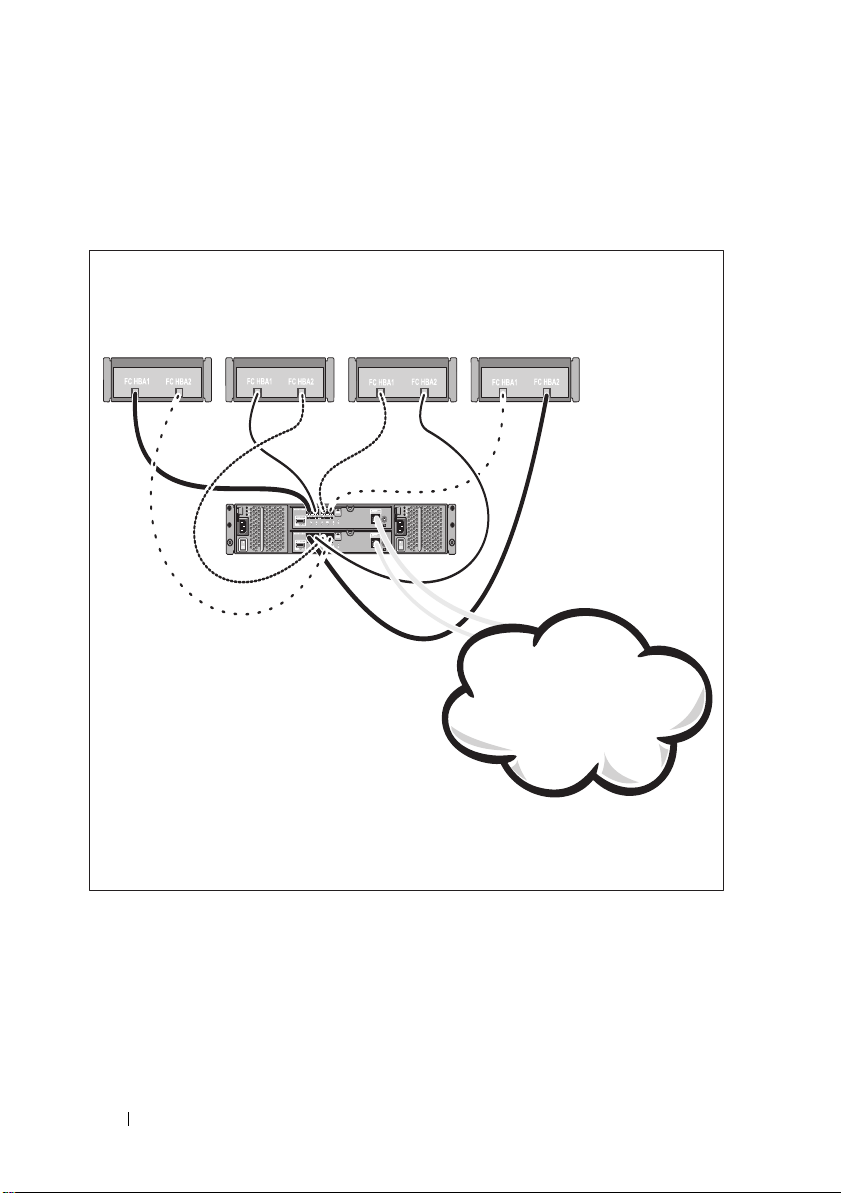
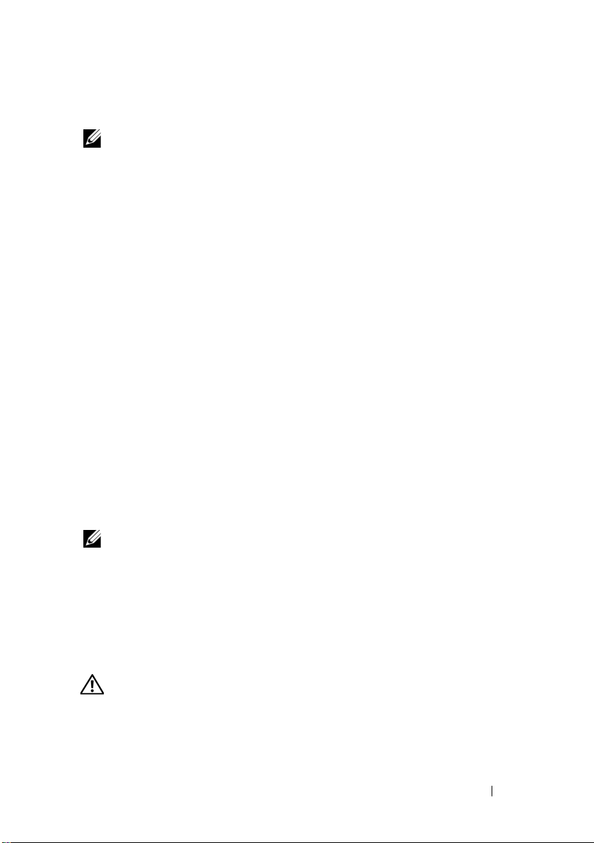
Common Configurations
Server 1
Server 2
PowerVault MD3600f
series storage array
Corporate, public, or
private network
Server 3 Server 4
Cabling Your Direct-Attached Hosts
6
Getting Started With Your System
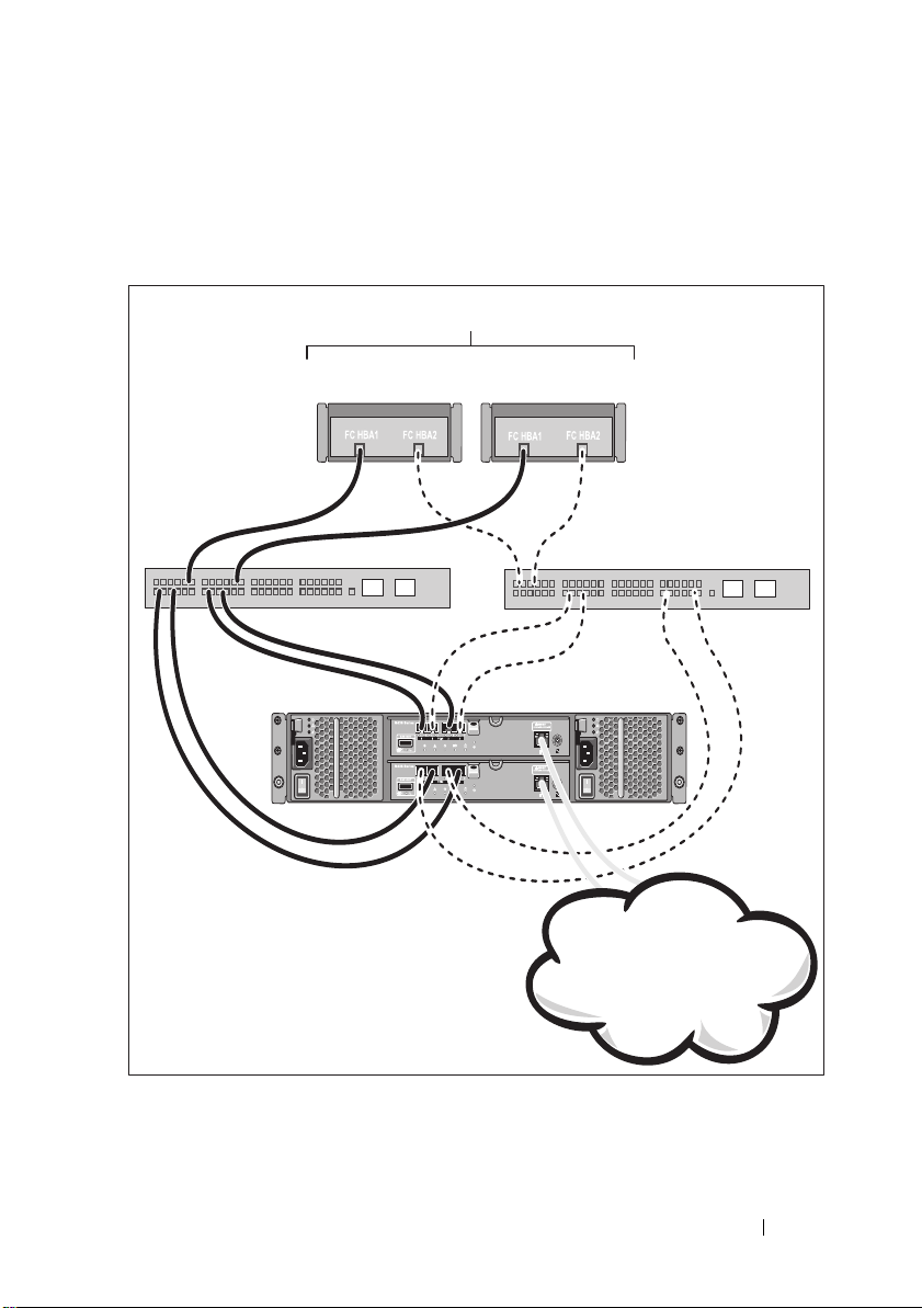
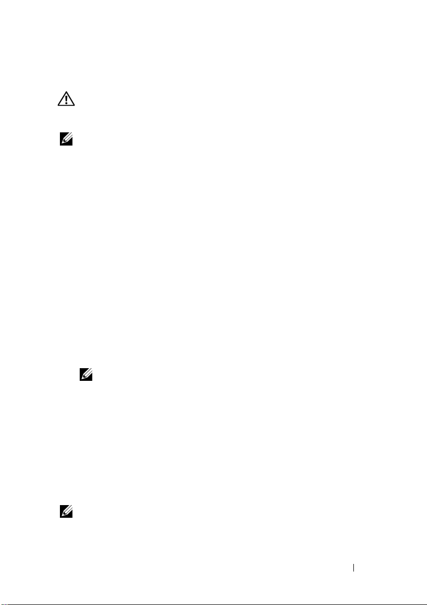
Cabling Your SAN-Attached Hosts
PowerVault MD3600f
series storage array
Switch 2Switch 1
Up to 64 hosts
Corporate, public, or
private network
The illustration below represents a redundant system. For example, a system
used in a remote replication environment.
Getting Started With Your System
7
Installation and Configuration
WARNING:
instructions that came with the system.
Unpacking the System
Unpack your system and identify each item with the packing list that shipped
with your system.
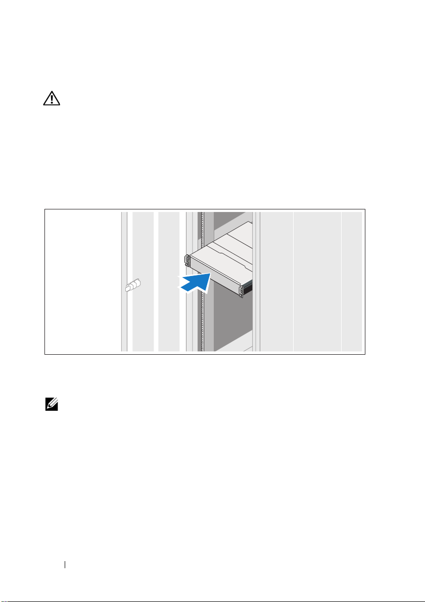
Installing the Rails and System in a Rack
Before performing the following procedure, review the safety
Assemble the rails and install the system in the rack following the safety
instructions and the rack installation instructions provided with your system.
NOTE:
To balance the weight load, it is recommended that you install the
PowerVault MD3600f series storage array at the bottom of the rack and the
PowerVault MD1200 series expansion enclosures above it.
8
Getting Started With Your System
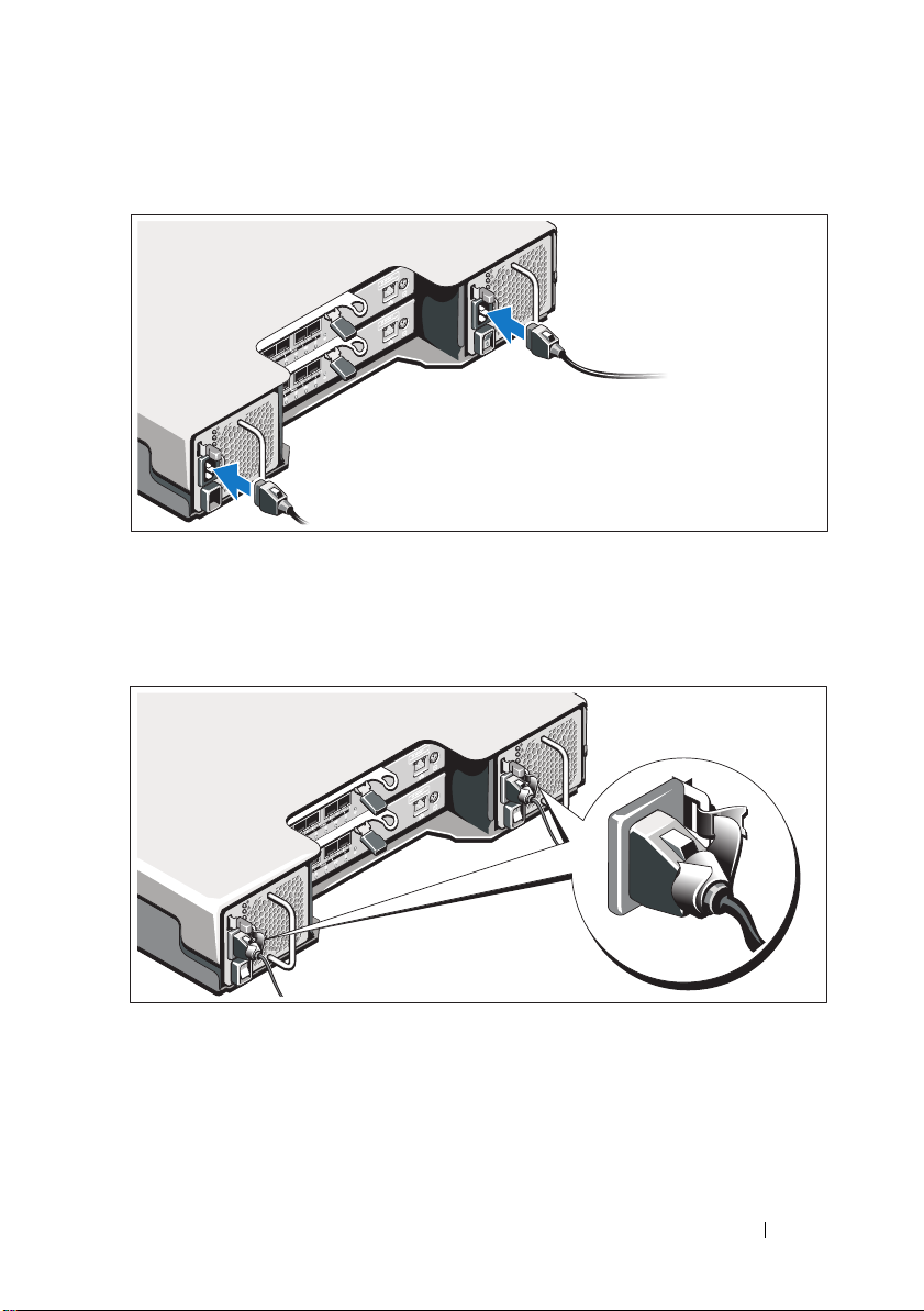
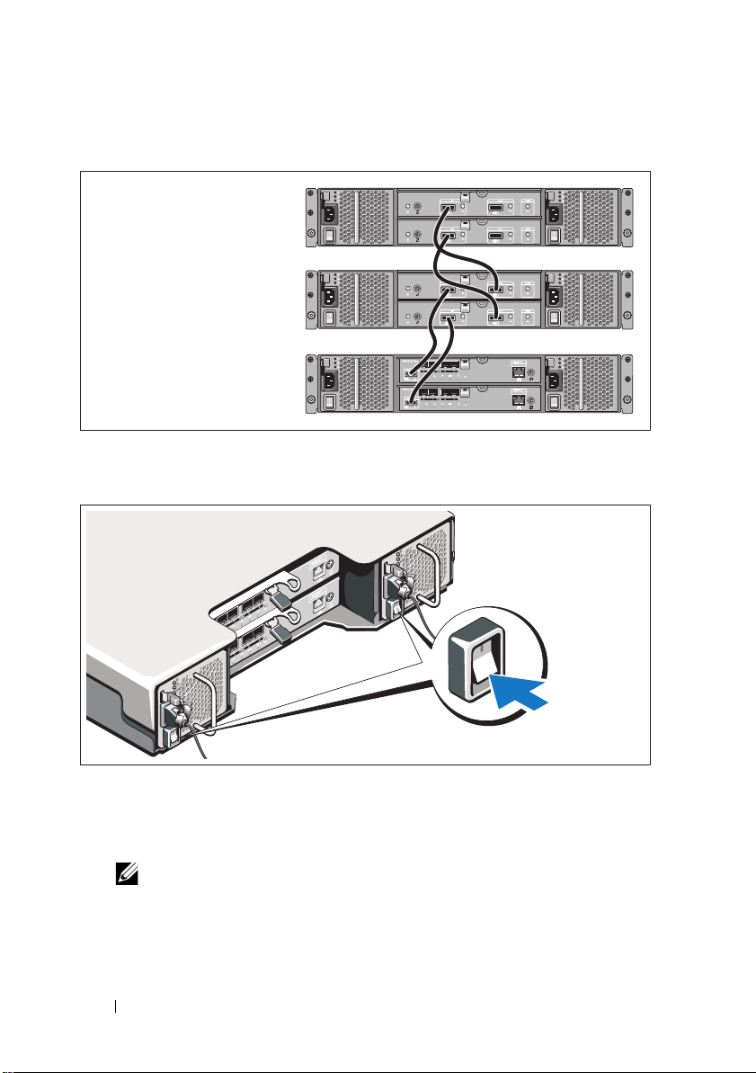
Connecting the Power Cable(s)
Ensure that the power switch is in the OFF position before connecting the
power cables. Connect the system’s power cable(s) to the system.
Securing the Power Cable(s)
Secure the cable(s) firmly to the bracket using the provided strap.
Plug the other end of the power cables into a grounded electrical outlet or
a separate power source such as an uninterrupted power supply (UPS) or
a power distribution unit (PDU). Each power supply must be connected
to a separate power circuit.
Getting Started With Your System
9
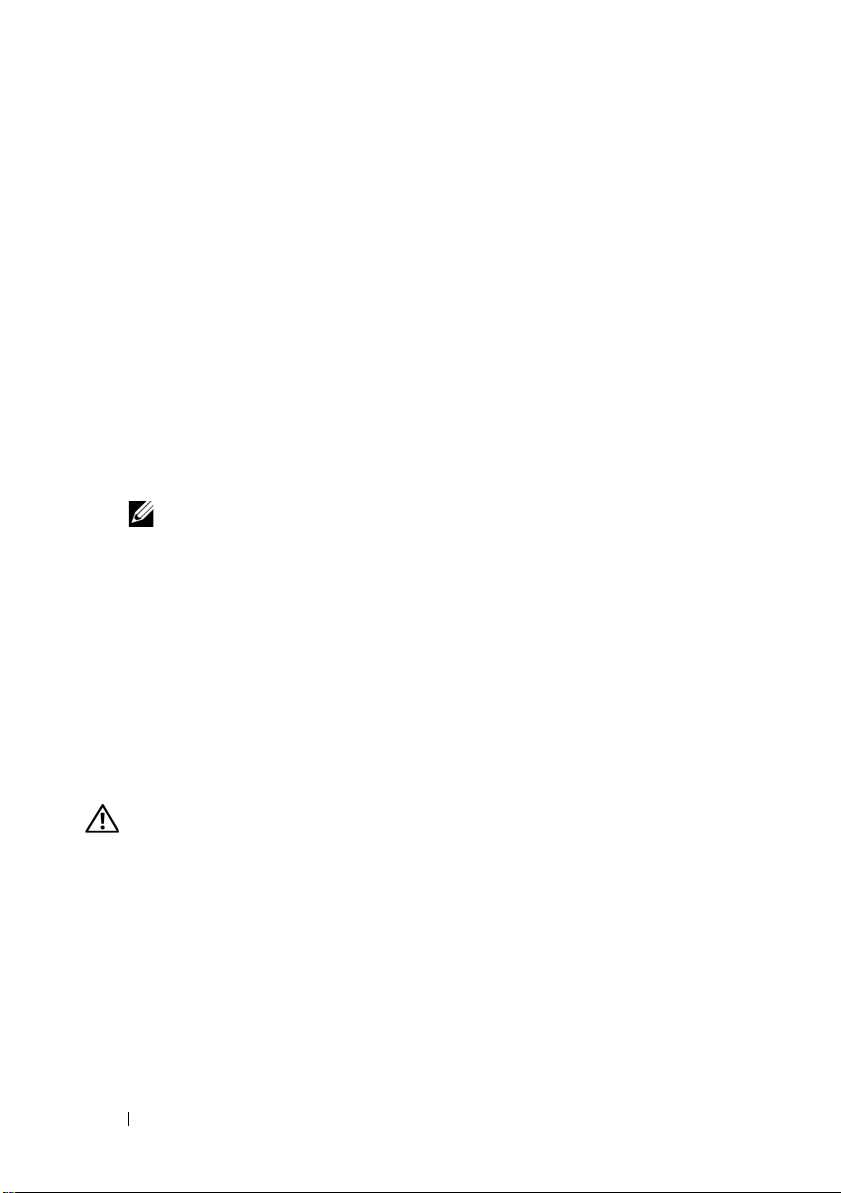
Installing and Removing SFP Modules
To install SFP modules:
1
If all the FC IN ports have an SFP module installed, go to step 5.
2
Remove the SFP module from the static protective package.
3
Remove the protective cap from the SFP module and SFP port. Store the
protective caps for future use.
4
Insert the SFP module into the host port until it clicks into place.
5
Connect an FC cable. See "Installing and Removing Fibre Channel
Cables" on page 10.
To remove SFP modules:
1
Remove the FC cable from the SFP module. See "Installing and Removing
Fibre Channel Cables" on page 10.
NOTE:
To avoid damaging the cable or the SFP module, disconnect
the FC cable before removing the SFP module.
2
Unlock the SFP module latch. For SFP modules that contain wire tabs,
unlock the SFP module latch by pulling the wire latch outward 90°.
3
With the SFP module latch in the unlocked position, remove the
SFP module. For SFP modules that contain wire tabs, grasp the wire latch
and pull the SFP module out of the port.
4
Replace the protective cap on the SFP module and the host port.
5
Place the SFP module into a static-protective package.
Installing and Removing Fibre Channel Cables
WARNING:
on system links with laser modules that operate at greater than Class 1 power
levels. Never look into the end of an optical fiber cable or open receptacle.
Before installing an FC cable, see "Guidelines for Using Fiber Optic Cables"
on page 4.
To install an FC cable:
1
If applicable, remove the protective cap from the SFP module and store
the protective cap for future use.
2
Remove the two protective caps from one end of the cable and store them
for future use.
10
Data processing environments can contain equipment transmitting
Getting Started With Your System
3
Insert the cable into an SFP module that is installed in the storage array.
The cable connector is keyed for correct installation. Holding the
connector, push in the cable until it clicks into place.
4
Remove the two protective caps from the other end of the cable and store
them future use.
5
Connect this end of the cable to one of the following devices:
– An SFP module that is installed in an FC switch port
– A FC HBA port
To remove an FC cable:
1
Press and hold the lever to release the latches before removing the cable
from the SFP module. Ensure that the levers are in the released position
when removing the cable. Do not grasp the SFP module plastic tab when
removing the cable.
2
On the end of the cable that connects into the SFP module or HBA,
press down and hold the lever to release the latches.
3
While pressing down the cable lever, pull the connector to remove the
cable from the SFP module.
4
Replace the protective caps on the cable ends.
5
Replace the protective cap on the SFP module.
Getting Started With Your System
11
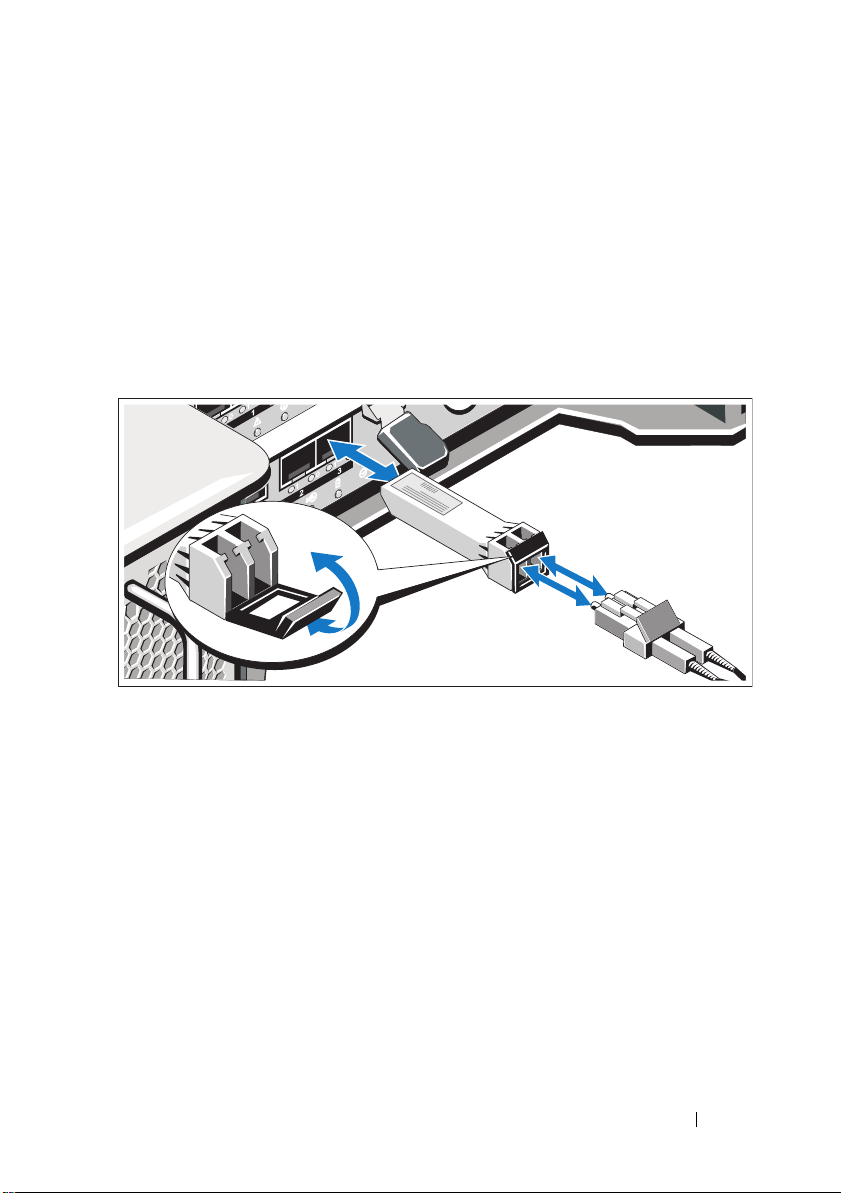
Cabling Your Expansion Enclosure
PowerVault MD3600f
series storage array
PowerVault MD1200
series expansion
enclosure 1 (optional)
PowerVault MD1200
series expansion
enclosure 2 (optional)
Turning On the Storage Array
Turn on the components in the following order:
FC switches (if used)
1
2
MD1200 series expansion enclosures (if used)
NOTE:
Before turning on the storage array, ensure that the expansion
enclosure status LED is blue.
12
Getting Started With Your System
3
MD3600f series storage array
NOTE:
Before turning on the host server(s), ensure that the storage array
status LED is blue.
4
Host server(s)
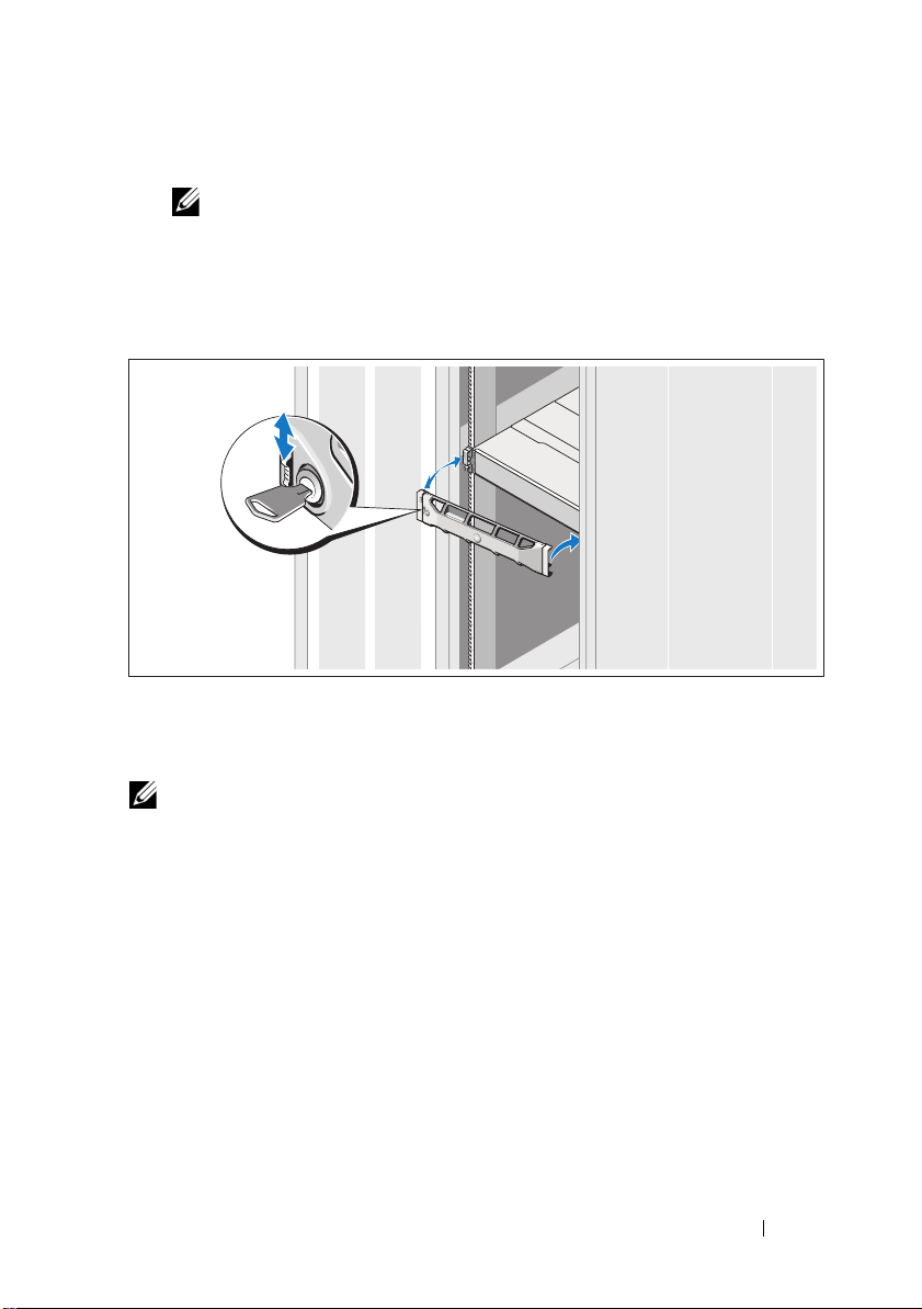
Installing the Bezel
Install the bezel (optional).
Installing HBAs and Drivers
NOTE:
Ensure that you read the Configuring Fibre Channel With the Dell MD3600f
Series Storage Array document before continuing with this procedure. For detailed
instructions about installing the MD storage software, setting up the enclosure, and
the post-installation tasks, see the Deployment Guide.
1
Physically install the HBAs.
2
Connect the cables.
3
Install the HBA drivers and the operating system HBA patches/hotfixes.
4
Ensure that the recommended HBA settings are applied.
Getting Started With Your System
13
Installing the MD Storage Software
NOTE:
For detailed instructions about installing the MD storage software, setting
up the enclosure, and the post-installation tasks, see the Deployment Guide.
The MD Storage Manager application configures, manages, and monitors the
storage array. To install the MD storage software:
1
Insert the MD series resource media.
Depending on your operating system, the installer may launch
automatically. If the installer does not launch automatically, navigate to
the root directory of the installation media (or downloaded installer
image) and run the
navigate to the root of the resource media and run the
NOTE:
By default, the Red Hat Enterprise Linux operating system mounts the
resource media with the -noexec mount option which does not allow you to
run executable files. To change this setting, see the Readme file in the root
directory of the installation media.
2
Select
Install MD Storage Software
3
Read and accept the license agreement.
4
Select one of the following installation options from the
drop-down menu:
•
Full (recommended)
software, host-based storage agent, multipath driver, and hardware
providers.
•
Host Only
drivers.
•
Management
providers.
Custom
•
5
Select the MD storage array model(s) you are setting up to serve as data
storage for this host server.
6
Choose whether to start the event monitor service automatically when the
host server reboots or manually
md_launcher.exe
file. For Linux-based systems,
autorun
file.
.
Install Set
—Installs the MD Storage Manager (client)
—Installs the host-based storage agent and multipath
—Installs the management software and hardware
—Allows you to select specific components.
NOTE:
This option is applicable only to Windows client software installation.
7
Confirm the installation location and click
14
Getting Started With Your System
Install
.
8
If prompted, reboot the host server once the installation completes.
9
Start the
10
Configure single initiator and multiple target zoning on your Fibre Channel
switches. For information about zoning, see the
11
If applicable, activate any premium features purchased with your storage
MD Storage Manager
NOTE:
If Dynamic Host Configuration Protocol (DHCP) is not used on the
network where the MD storage array’s management ports are connected, it is
recommended that you enable IPv6 on the management station to discover
the storage array(s).
and discover the array(s).
Deployment Guide
.
array. If you purchased premium features, see the printed activation card
shipped with your storage array.
NOTE:
The MD Storage Manager installer automatically installs the required
drivers, firmware, and operating system patches/hotfixes to operate your storage
array. These drivers and firmware are also available at support.dell.com. In
addition, see the Support Matrix at support.dell.com/manuals for any additional
settings and/or software required for your specific storage array.
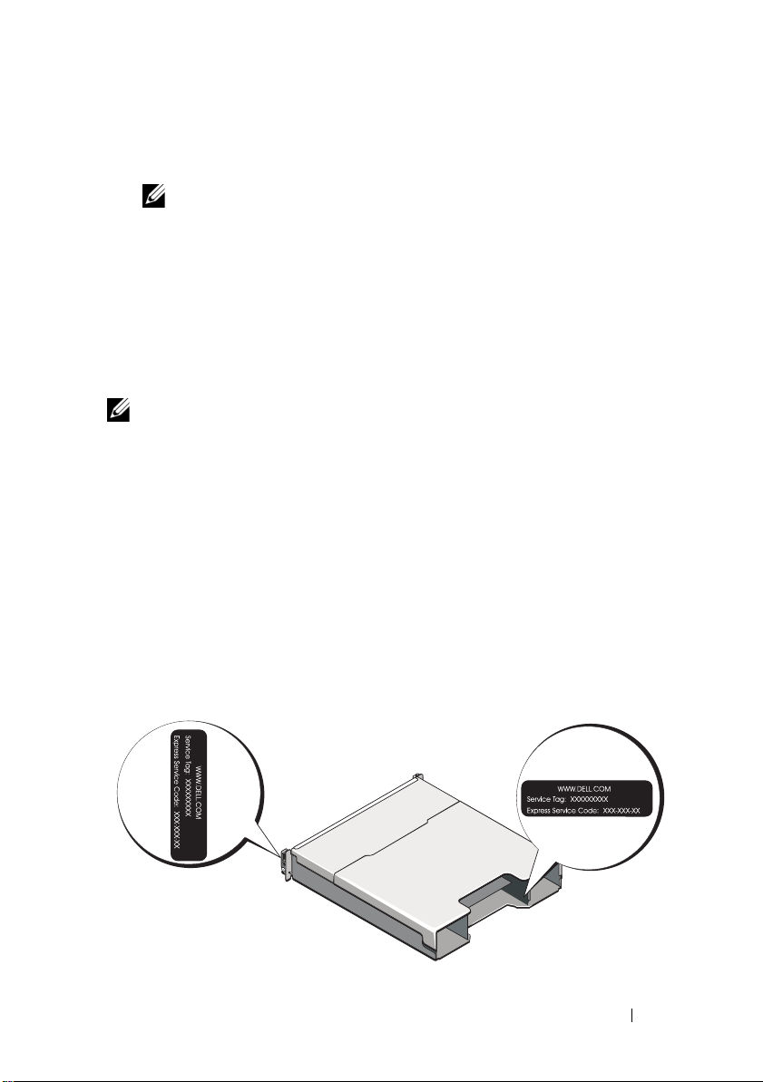
Locating Your Service Tag
Your system is identified by a unique Express Service Code and Service Tag
number. The Express Service Code and Service Tag are found on the front
of the system and at the back of the system next to the RAID controller
modules. This information is used by Dell to route support calls to the
appropriate personnel.
Getting Started With Your System
15
NOM Information (Mexico Only)
The following information is provided on the device described
in this document in compliance with the requirements of the
official Mexican standards (NOM):
Importer:
Model number: E03J and E04J
Supply voltage: 100–240 V CA
Frequency: 50/60 Hz
Current consumption: 8.6 A
Technical Specifications
Drives
PowerVault MD3600f Up to twelve 3.5" SAS hot-swappable hard drives
(3.0 Gbps and 6.0 Gbps)
PowerVault MD3620f Up to twenty four 2.5" SAS hot-swappable
hard drives (3.0 Gbps and 6.0 Gbps)
RAID Controller Modules
RAID controller modules
Back-Panel Connectors (Per RAID Controller Module)
FC connectors Four FC IN ports to connect hosts
SAS connector
Serial connector One 6-pin mini-DIN connector
16
Getting Started With Your System
• One or two hot-swappable modules with
temperature sensors
• 2 GB of cache per controller
One SAS OUT port for expansion to an additional
PowerVault MD12xx enclosure
NOTE:
The SAS connector is SFF-8088 compliant.
NOTE:
For technical support use only.

Back-Panel Connectors (Per RAID Controller Module) (continued)
Management Ethernet
connector
Expansion
PowerVault MD1200 series Supports a maximum of 192 hard drives with any
Backplane Board
Connectors
Sensors Two temperature sensors
One 100/1000 Base-T port Ethernet for out-of-band
management of the enclosure
NOTE:
The default management port IP addresses for
the primary and secondary RAID controller modules
are 192.168.128.101 and 192.168.128.102, respectively.
By default, the management ports are set to DHCP.
If the controller is unable to get an IP address
configuration from a DHCP server within a specified
time out period (approximately 3 minutes), it defaults
back to static IP addressing. For more information,
see the Deployment Guide.
combination of PowerVault MD1200 or PowerVault
MD1220 expansion enclosures. Support for 192 hard
drives is a Premium Feature and requires activation.
The maximum number of hard drives supported
without using the Premium Feature is 120.
Redundant path connectivity provides redundant
data paths to each hard drive.
• 12 or 24 SAS hard-drive connectors
• Two power supply/cooling fan module connectors
• Two sets of RAID controller module connectors
• One control panel connector for front LEDs and
system identification button
Getting Started With Your System
17

LED Indicators
Front panel
Hard-drive carrier
Power supply/cooling fan Three LED status indicators for power supply status,
RAID controller module 14 single-color LEDs:
• One two-color LED indicator for system status
• Two single-color LED indicators for power and
enclosure mode
NOTE:
The enclosure mode LED is not applicable to
the PowerVault MD3600f series storage array.
• One single-color activity LED
• One two-color LED status indicator per drive
power supply/fan fault, and AC status
• One battery fault
• One cache active
• One controller fault
• One controller power
• One system identification
• One management Ethernet activity
• Eight FC link or fault
2 two-color LEDs:
• One SAS OUT link or fault
• One management Ethernet link speed
Switch
System identification button Located on the front control panel. This button is
used to locate a system within a rack.
Enclosure mode switch Located on the front of the system. This switch is
not applicable to the PowerVault MD3600f series
storage array.
Password reset switch Located on the back-panel of the RAID controller
module. This switch is used to reset the storage array
password.
18
Getting Started With Your System

Power Supplies
AC power supply (per power supply)
Wattage
Vo lt ag e
Heat dissipation
Maximum inrush current
Available Hard Drive Power (Per Slot)
PowerVault MD3600f 25 W
PowerVault MD3620f 12 W
RAID Controller Module Power (Per Slot)
Maximum power consumption 100 W
Physical
PowerVault MD3600f
Height
Width
Depth
Weight (maximum
configuration)
Weig ht ( empt y)
PowerVault MD3620f
Height
Width
Depth
Weight (maximum
configuration)
Weig ht ( empt y)
600 W
100–240 VAC (8.6 A–4.3 A)
100 W
Under typical line conditions and over the entire
system ambient operating range, the inrush current
may reach a maximum of 55 A per power supply for
10 ms or less.
8.68 cm (3.41")
44.63 cm (17.57")
60.20 cm (23.70")
29.30 kg (64.6 lb)
8.84 kg (19.5 lb)
8.68 cm (3.41")
44.63 cm (17.57")
54.90 cm (21.61")
24.22 kg (53.4 lb)
8.61 kg (19 lb)
Getting Started With Your System
19

Environmental
NOTE:
For additional information about environmental measurements for specific
system configurations, see www.dell.com/environmental_datasheets.
Te mp e ra t u re
Operating
Storage
Relative humidity
Operating
Storage
Maximum vibration
Operating
Storage
Maximum shock
Operating
Storage
Altitude
Operating
Storage
Airborne Contaminant Level
Class
10 °C to 35 °C (50 °F to 95 °F) with a maximum
temperature gradation of 10 °C per hour
NOTE:
For altitudes above 2950 feet, the maximum
operating temperature is derated 1ºF/550 ft.
–40° to 65°C (–40° to 149°F) with a maximum
temperature gradation of 20°C per hour
20% to 80% (noncondensing) with a maximum
humidity gradation of 10% per hour
5% to 95% (noncondensing)
0.25 G at 3–200 Hz for 15 min
0.5 G at 3–200 Hz for 15 min
One shock pulse in the positive z axis (one pulse on
each side of the system) of 31 G for 2.6 ms in the
operational orientation
Six consecutively executed shock pulses in the
positive and negative x, y, and z axes (one pulse on
each side of the system) of 71 G for up to 2 ms
–16 to 3048 m (–50 to 10,000 ft)
NOTE:
For altitudes above 2950 feet, the maximum
operating temperature is derated 1ºF/550 ft.
–16 to 10,600 m (–50 to 35,000 ft)
G1 as defined by ISA-S71.04-1985
20
Getting Started With Your System

Disková pole Dell PowerVault
MD3600f a MD3620f
Začínáme se systémem
Číslo modelu série: E03J a E04J
Poznámky a upozornění
POZNÁMKA:
využití počítače.
UPOZORNĚNÍ:
dat v případě nedodržení pokynů.
VAROVÁNÍ:
úrazu nebo smrti.
____________________
Informace v této publikaci se mohou bez předchozího upozornění změnit.
© 2011 Dell Inc. Všechna práva vyhrazena.
Jakákoli reprodukce těchto materiálů bez písemného povolení společnosti Dell Inc. je přísně zakázána.
Ochranné známky použité v tomto textu: Dell™, logo DELL a PowerVault™ jsou ochranné známky
společnosti Dell Inc. Microsoft
ochranné známky společnosti Microsoft Corporation ve Spojených státech anebo v jiných zemích.
®
Red Hat
v USA a v dalších zemích. SUSE
a dalších zemích. VMware
nebo v dalších zemích.
Ostatní ochranné známky a obchodní názvy mohou být v této publikaci použity v souvislosti
s právními subjekty, které si na tyto ochranné známky a názvy svých produktů činí nárok. Společnost
Dell Inc. se zříká všech vlastnických nároků na ochranné známky a obchodní názvy jiné než vlastní.
a Red Hat Enterprise Linux® jsou registrované ochranné známky společnosti Red Hat, Inc.
POZNÁMKA označuje důležité informace, které pomáhají k lepšímu
VÝSTRAHA poukazuje na možnost poškození hardwaru nebo ztráty
VAROVÁNÍ upozorňuje na potenciální nebezpečí poškození majetku,
®
a Windows Server® jsou bud’ ochranné známky, nebo registrované
®
je registrovaná ochranná známka společnosti Novell, Inc. v USA
®
je registrovaná ochranná známka společnosti VMware, Inc. v USA a/
Číslo modelu série: E03J a E04J
2011 - 08 Č. dílu NKX4V Rev. A02
Než začnete
POZNÁMKA:
MD3600f jak Dell PowerVault MD3600f, tak i Dell PowerVault MD3620f. Název rozšiřující
skříň série Dell PowerVault MD1200 se vztahuje jak k Dell PowerVault MD1200, tak k
Dell PowerVault MD1220.
Než začnete s instalací diskového pole Dell PowerVault MD3600f, vezměte v
úvahu osvědčené metody, s jejichž pomocí zajistíte, aby diskové pole pracovalo s
maximální účinností a nabízelo plnou redundanci (pokud je třeba).
• Chcete-li umožnit redundanci, je třeba mezi hostitelským systémem a
diskovým polem zajistit připojení dvěma sběrnicemi HBA typu Fibre
Channel (FC). Pokud redundance není třeba, je k diskovému poli
připojena pouze jedna sběrnice FC HBA. Seznam podporovaných sběrnic
HBA naleznete v
Fibre Channel s diskovým polem série Dell MD3600f
instalaci ovladačů HBA. Oba dokumenty si můžete stáhnout ze stránek
support.dell.com/manuals
• Než mezi hostitelským serverem a diskovým polem připojíte jakékoli
kabely, označte každý port a konektor.
• Pokud jsou sesít’ované systémy pod napětím, vždy dodržujte správné
postupy při zapínání a vypínání systémů. Musíte též zajistit, aby důležité
sít’ové komponenty měly oddělené hlavní obvody.
Práce s moduly SFP a optickými kabely
V tomto dokumentu označuje název diskové pole série Dell PowerVault
matici odborné pomoci
. V
příručce o konfiguraci
naleznete informace o
.
POZNÁMKA:
Tento dokument se moduly SFP zabývá jen obecně.
Moduly SFP+ jsou podporovány u 8GB připojení typu Fibre Channel.
Každý řadič úložišt’může obsahovat až čtyři hostitelské porty FC. Malý zapojitelný
modul SFP slouží k připojení hostitelského portu k hostitelskému systému nebo
k přepínači. Modul SFP se vkládá do portu, a poté se k modulu SFP připojí
optický kabel. Opačný konec optického kabelu se připojí ke konektoru optického
rozhraní bu na FC HBA na hostitelském systému, nebo na přepínači. Moduly
SFP patří mezi laserové výrobky.
VAROVÁNÍ:
na spojích systému s laserovými moduly, které pracují na vyšších úrovních, než je
Třída 1. Nikdy se nedívejte do konce optického kabelu nebo do otevřené zásuvky.
Prostředí zpracování dat může obsahovat vybavení využívající přenos
Začínáme se systémem
23

Pokyny k používání optických kabelů
• Neved’te kabely podél sklápěcího ramene pro správu kabelů.
• U zařízení na vysouvacích kolejnicích je třeba ponechat kabely dostatečně
volné, aby se při natažení neohýbaly na průměr menší, než je 76 mm (3")
nebo na poloměr menší než 38 mm (1,5"). Při zatažení by se kabely neměly
skřípnout.
• Ved’te kabely mimo místa, kde by je mohla poškodit jiná zařízení ve
stojanu.
• Nepoužívejte na vázání kabelů plastová poutka místo dodaných řemínků.
• Neutahujte řemínky přespříliš ani kabely neohýbejte na průměr menší než
76 mm (3") nebo na poloměr menší než 38 mm (1,5").
• Nezatěžujte kabely u bodů připojení těžkými předměty. Ujistěte se, že jsou
kabely dobře podloženy.
Pokyny pro používání modulů SFP
Diskové pole vyžaduje moduly SFP. Moduly SFP převádějí elektrické signály na
optické signály, které jsou třeba pro přenosy FC z/do řadiče diskových polí
RAID. Po instalaci modulů SFP slouží optické kabely k připojení diskových polí
k jiným zařízením FC. Před instalací modulů SFP a optických kabelů si přečtěte
následující informace:
• S diskovými poli série PowerVault MD3600f používejte pouze SFP
podporované společností Dell. Jiné generické SFP nejsou podporovány a
nemusí s diskovými poli fungovat.
• Kryt modulu SFP obsahuje neoddělitelná vodítka, která vám mají zabránit
vložit modul SFP nesprávně.
• Při vkládání modulu SFP do portu FC nevyvíjejte přílišnou sílu. Pokud
modul SFP do portu zarazíte silou, můžete tento modul SFP nebo port
poškodit.
• Pokud je port zapnutý, můžete modul SFP nainstalovat nebo odstranit.
• Modul SFP je třeba nainstalovat do portu předtím, než připojíte optický
kabel.
• Předtím, než odstraníte modul SFP z portu, musíte z modulu SFP
odstranit optický kabel.
OSTRZEŻENIE:
elektřinu opatrně, aby je statická elektřina nepoškodila.
24
Začínáme se systémem
Při manipulaci zacházejte se zařízeními citlivými na statickou
Další dokumenty a média, které můžete potřebovat
VAROVÁNÍ:
dodány se systémem. Informace o záruce jsou součástí tohoto dokumentu nebo
jsou přiloženy samostatně.
POZNÁMKA:
support.dell.com/manuals
• Pokyny k instalaci do stojanu dodané se stojanovým řešením popisují
instalaci systému do stojanu.
•
Příručka majitele hardwaru
popisuje řešení problémů se systémem a instalaci nebo výměnu
komponent.
•
Instalační příručka
hardwaru.
•
Příručka CLI
diskového pole používat rozhraní CLI.
•
Příručka programátora SMI-S
poskytovatele SMI-S a o programování SMI-S.
• Média dodaná se systémem obsahují dokumentaci a nástroje pro
konfiguraci a správu systému. Mohou být dodána například média týkající
se operačního systému, softwaru pro správu systému, aktualizací systému a
komponent zakoupených se systémem.
Prostudujte si informace o bezpečnosti a předpisech, které byly
Veškeré dokumenty pro systém PowerVault MD3600f lze získat na adrese
.
obsahuje informace o funkcích systému a
obsahuje informace o instalaci a konfiguraci softwaru a
obsahuje informace o tom, jak ke konfiguraci a správě
obsahuje informace o používání
POZNÁMKA:
support.dell.com/manuals
ostatních dokumentech.
Vždy nejprve zkontrolujte a pročtěte aktualizace uvedené na adrese
, protože tyto aktualizace často nahrazují informace v
Podporované operační systémy
• Microsoft Windows Server
• Red Hat Enterprise Linux
• SUSE Linux Enterprise Server
•VMware
POZNÁMKA:
systémů naleznete v
Nejnovější informace o verzích všech podporovaných operačních
matici odborné pomoci
na adrese
support.dell.com/manuals
Začínáme se systémem
.
25

Obvyklé konfigurace
Server 1
Server 2
Disková pole série
PowerVault MD3600f
Firemní, veřejná nebo
soukromá sít’
Server 3 Server 4
Připojení hostitelských systémů v DAS
26
Začínáme se systémem

Připojení hostitelských systémů v SAN
Disková pole série
MD3600f
Přepínač 2Přepínač 1
Až 64 hostitelských systémů
Firemní, veřejná nebo
soukromá sít’
Níže uvedený obrázek představuje redundantní systém. Například systém
používaný ve vzdáleném replikačním prostředí.
Začínáme se systémem
27

Instalace a konfigurace
VAROVÁNÍ:
pokyny dodané se systémem.
Rozbalení systému
Rozbalte systém a zkontrolujte každou položku dle seznamu, který jste obdrželi
společně se systémem.
Instalace kolejniček a systému do stojanu
Před provedením následujícího postupu si prostudujte bezpečnostní
Sestavte kolejničky a nainstalujte systém do stojanu podle bezpečnostních
pokynů a pokynů k instalaci do stojanu dodaných se systémem.
POZNÁMKA:
pole série PowerVault MD3600f do spodní části stojanu
PowerVault MD1200 nad ně.
28
Začínáme se systémem
Chcete-li správně vyvážit stojan, doporučujeme namontovat diskové
a rozšiřující skříně série
 Loading...