

Dell Powervault DL2300 User Manual

Dell PowerVault DL2300
Owner's Manual
Regulatory Model: E14S Series
Regulatory Type: E14S001

Notes, Cautions, and Warnings
NOTE: A NOTE indicates important information that helps you make better use of your computer.
CAUTION: A CAUTION indicates either potential damage to hardware or loss of data and tells you how to avoid the
problem.
WARNING: A WARNING indicates a potential for property damage, personal injury, or death.
© 2012 Dell Inc.
Trademarks used in this text: Dell™, the Dell logo, Dell Boomi™, Dell Precision™ , OptiPlex™, Latitude™, PowerEdge™, PowerVault™,
PowerConnect™, OpenManage™, EqualLogic™, Compellent™, KACE™, FlexAddress™, Force10™ and Vostro™ are trademarks of Dell
Inc. Intel®, Pentium®, Xeon®, Core® and Celeron® are registered trademarks of Intel Corporation in the U.S. and other countries. AMD
is a registered trademark and AMD Opteron™, AMD Phenom™ and AMD Sempron™ are trademarks of Advanced Micro Devices, Inc.
Microsoft®, Windows®, Windows Server®, Internet Explorer®, MS-DOS®, Windows Vista® and Active Directory® are either trademarks
or registered trademarks of Microsoft Corporation in the United States and/or other countries. Red Hat® and Red Hat
Enterprise Linux® are registered trademarks of Red Hat, Inc. in the United States and/or other countries. Novell® and SUSE® are
registered trademarks of Novell Inc. in the United States and other countries. Oracle® is a registered trademark of Oracle Corporation
and/or its affiliates. Citrix®, Xen®, XenServer® and XenMotion® are either registered trademarks or trademarks of Citrix Systems, Inc. in
the United States and/or other countries. VMware
trademarks of VMware, Inc. in the United States or other countries.
Corporation.
2012 - 09
®
,
Virtual SMP
®
®
,
vMotion
®
is a registered trademark of International Business Machines
IBM
,
vCenter
®
and
vSphere
®
are registered trademarks or
®
®
Rev. A00

Contents
Notes, Cautions, and Warnings...................................................................................................2
1 About Your System......................................................................................................................9
Front Panel Features And Indicators........................................................................................................................9
Diagnostic Indicators..............................................................................................................................................10
Hard-Drive Indicator Patterns................................................................................................................................12
Back-Panel Features And Indicators.....................................................................................................................13
NIC Indicator Codes................................................................................................................................................14
Power Indicator Codes...........................................................................................................................................14
Other Information You May Need...........................................................................................................................16
2 Using The System Setup And Boot Manager.......................................................................17
Entering System Setup............................................................................................................................................17
Responding To Error Messages.......................................................................................................................18
Using The System Setup Navigation Keys.......................................................................................................18
System Setup Options.............................................................................................................................................18
System Setup Main Screen..............................................................................................................................18
System BIOS Screen........................................................................................................................................18
System Information Screen..............................................................................................................................19
Memory Settings Screen.................................................................................................................................19
Processor Settings Screen..............................................................................................................................20
Boot Settings Screen.......................................................................................................................................21
Integrated Devices Screen..............................................................................................................................22
Serial Communications Screen........................................................................................................................23
System Profile Settings Screen........................................................................................................................23
System Security Screen...................................................................................................................................24
Miscellaneous Settings....................................................................................................................................25
System And Setup Password Features..................................................................................................................26
Assigning A System And/Or Setup Password..................................................................................................26
Deleting Or Changing An Existing System And/Or Setup Password................................................................27
Using Your System Password To Secure Your System....................................................................................27
Operating With A Setup Password Enabled....................................................................................................27
Embedded System Management............................................................................................................................28
3 Installing System Components................................................................................................29
Recommended Tools..............................................................................................................................................29
Front Bezel (Optional).............................................................................................................................................29

Removing The Front Bezel................................................................................................................................29
Installing The Front Bezel.................................................................................................................................30
Opening And Closing The System...........................................................................................................................30
Opening The System........................................................................................................................................30
Closing The System..........................................................................................................................................31
Inside The System...................................................................................................................................................31
Cooling Shroud.......................................................................................................................................................32
Removing The Cooling Shroud.........................................................................................................................32
Installing The Cooling Shroud..........................................................................................................................33
System Memory......................................................................................................................................................33
Mode-Specific Guidelines................................................................................................................................34
Supported Memory Configurations..................................................................................................................35
Removing Memory Modules............................................................................................................................36
Installing Memory Modules.............................................................................................................................37
Hard Drives.............................................................................................................................................................38
Removing A 2.5 Inch Hard-Drive Blank (Back).................................................................................................38
Installing A 2.5 Inch Hard-Drive Blank (Back)..................................................................................................38
Removing A 3.5 Inch Hard-Drive Blank............................................................................................................39
Installing A 3.5 Inch Hard-Drive Blank.............................................................................................................39
Removing A Hot-Swap Hard Drive...................................................................................................................39
Installing A Hot-Swap Hard Drive....................................................................................................................40
Removing A Hard Drive From A Hard-Drive Carrier.........................................................................................41
Installing A Hard Drive Into A Hard-Drive Carrier............................................................................................41
Cooling Fans............................................................................................................................................................41
Removing A Cooling Fan...................................................................................................................................42
Installing A Cooling Fan....................................................................................................................................43
Removing The Cooling-Fan Assembly..............................................................................................................43
Installing The Cooling-Fan Assembly...............................................................................................................44
Internal USB Memory Key (Optional).....................................................................................................................44
Replacing The Internal USB Key......................................................................................................................44
PCIe Card Holder....................................................................................................................................................45
Removing The PCIe Card Holder......................................................................................................................45
Installing The PCIe Card Holder.......................................................................................................................46
Opening And Closing The PCIe Card Holder Latch..........................................................................................46
Cable Retention Bracket.........................................................................................................................................47
Removing The Cable Retention Bracket..........................................................................................................47
Installing The Cable Retention Bracket............................................................................................................48
Expansion Cards And Expansion-Card Risers........................................................................................................48
Expansion Card Installation Guidelines............................................................................................................48
Removing An Expansion Card From The Expansion-Card Riser 2 Or 3............................................................49
Installing An Expansion Card Into The Expansion-Card Riser 2 Or 3...............................................................50
Removing An Expansion Card From The Expansion-Card Riser 1....................................................................51

Installing An Expansion Card Into The Expansion-Card Riser 1.......................................................................52
Removing Expansion-Card Risers....................................................................................................................53
Installing Expansion-Card Risers.....................................................................................................................56
SD vFlash Card........................................................................................................................................................56
Replacing An SD vFlash Card...........................................................................................................................56
Removing The vFlash Media Unit.....................................................................................................................57
Installing The vFlash Media Unit......................................................................................................................58
Internal Dual SD Module........................................................................................................................................59
Removing The Internal Dual SD Module..........................................................................................................59
Installing The Internal Dual SD Module...........................................................................................................60
Internal SD Card.....................................................................................................................................................61
Removing An Internal SD Card.........................................................................................................................61
Installing An Internal SD Card..........................................................................................................................61
Integrated Storage Controller Card........................................................................................................................61
Removing The Integrated Storage Controller Card..........................................................................................62
Installing The Integrated Storage Controller Card...........................................................................................63
Network Daughter Card..........................................................................................................................................63
Removing The Network Daughter Card...........................................................................................................63
Installing The Network Daughter Card.............................................................................................................64
Processors..............................................................................................................................................................64
Removing A Processor.....................................................................................................................................65
Installing A Processor......................................................................................................................................68
Power Supplies.......................................................................................................................................................69
Hot Spare Feature............................................................................................................................................70
Removing An AC Power Supply.......................................................................................................................70
Installing An AC Power Supply........................................................................................................................71
Removing The Power Supply Blank.................................................................................................................71
Installing The Power Supply Blank..................................................................................................................72
System Battery.......................................................................................................................................................72
Replacing The System Battery.........................................................................................................................72
Hard-Drive Backplane............................................................................................................................................73
Removing The Hard-Drive Backplane..............................................................................................................73
Installing The Hard-Drive Backplane...............................................................................................................75
Removing The Hard-Drive Backplane (Back)..................................................................................................76
Installing The Hard-Drive Backplane (Back)....................................................................................................77
Control Panel..........................................................................................................................................................78
Removing The Control Panel............................................................................................................................78
Installing The Control Panel.............................................................................................................................79
Removing The I/O Panel...................................................................................................................................80
Installing The I/O Panel....................................................................................................................................81
System Board..........................................................................................................................................................81
Removing The System Board...........................................................................................................................81

Installing The System Board............................................................................................................................83
4 Troubleshooting Your System.................................................................................................85
Safety First—For You And Your System.................................................................................................................85
Troubleshooting System Startup Failure................................................................................................................85
Troubleshooting External Connections...................................................................................................................85
Troubleshooting The Video Subsystem..................................................................................................................85
Troubleshooting A USB Device..............................................................................................................................85
Troubleshooting A Serial I/O Device......................................................................................................................86
Troubleshooting A NIC............................................................................................................................................86
Troubleshooting A Wet System..............................................................................................................................86
Troubleshooting A Damaged System.....................................................................................................................87
Troubleshooting The System Battery.....................................................................................................................88
Troubleshooting Power Supplies............................................................................................................................88
Troubleshooting Cooling Problems.........................................................................................................................88
Troubleshooting Cooling Fans................................................................................................................................89
Troubleshooting System Memory...........................................................................................................................89
Troubleshooting An Internal USB Key....................................................................................................................90
Troubleshooting An SD Card..................................................................................................................................90
Troubleshooting A Hard Drive................................................................................................................................91
Troubleshooting A Storage Controller....................................................................................................................91
Troubleshooting Expansion Cards..........................................................................................................................92
Troubleshooting Processors...................................................................................................................................93
5 Using System Diagnostics.......................................................................................................95
Dell Online Diagnostics...........................................................................................................................................95
Dell Embedded System Diagnostics.......................................................................................................................95
When To Use The Embedded System Diagnostics..........................................................................................95
Running The Embedded System Diagnostics...................................................................................................95
System Diagnostic Controls.............................................................................................................................96
6 Jumpers And Connectors........................................................................................................97
System Board Jumper Settings..............................................................................................................................97
System Board Connectors......................................................................................................................................98
Disabling A Forgotten Password..........................................................................................................................100
7 Technical Specifications.......................................................................................................101
8 System Messages...................................................................................................................105
System Error Messages........................................................................................................................................105
Warning Messages...............................................................................................................................................118
Diagnostic Messages...........................................................................................................................................118

Alert Messages.....................................................................................................................................................119
9 Getting Help..............................................................................................................................121
Contacting Dell.....................................................................................................................................................121

8
About Your System
Front Panel Features And Indicators
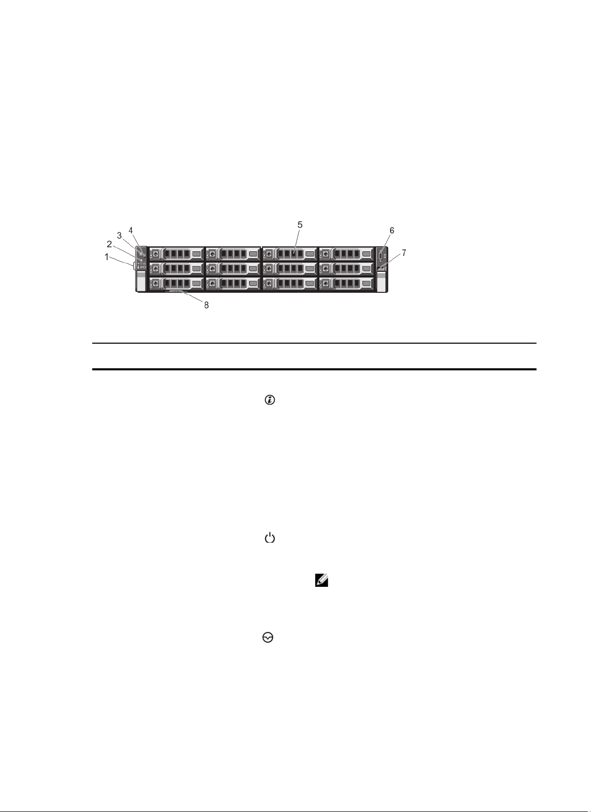
Figure 1. Front-Panel Features and Indicators
1
Item Indicator, Button, or
Connector
1 Diagnostic indicators The diagnostic indicators light up to display error status.
2 System identification button The identification buttons on the front and back panels
3 Power-on indicator, power
button
4 NMI button Used to troubleshoot software and device driver errors
Icon Description
can be used to locate a particular system within a rack.
When one of these buttons is pressed, the system status
indicator on the back flashes until one of the buttons is
pressed again.
Press to toggle the system ID on and off.
If the system stops responding during POST, press and
hold the system ID button for more than five seconds to
enter BIOS progress mode.
To reset the iDRAC (if not disabled in F2 iDRAC setup)
press and hold the button for more than 15 seconds.
The power-on indicator lights when the system power is
on. The power button controls the power supply output to
the system.
NOTE: On ACPI-compliant operating systems, turning
off the system using the power button causes the
system to perform a graceful shutdown before power
to the system is turned off.
when running certain operating systems. This button can
be pressed using the end of a paper clip.
9

Item Indicator, Button, or
Connector
5 Hard drives Up to twelve 3.5 inch hot-swappable hard drives.
6 Video connector Allows you to connect a VGA display to the system.
7 USB connector Allows you to connect USB devices to the system. The
8 Information tag A slide-out label panel which allows you to record system
Icon Description
Use this button only if directed to do so by qualified
support personnel or by the operating system's
documentation.
port is USB 2.0-compliant.
information such as Service Tag, NIC, MAC address, and
so on as per your need.
Diagnostic Indicators
The diagnostic indicators on the system front panel display error status during system startup.
NOTE: No diagnostic indicators are lit when the system is switched off. To start the system, plug it into a working
power source and press the power button.
The following section describes system conditions and possible corrective actions associated with these indicators:
Health indicator
Condition Corrective Action
If the system is on,
and in good health,
the indicator lights
solid blue.
The indicator blinks
amber if the system
is on or in standby,
and any error exists
(for example, a failed
fan or hard drive)
Hard-drive indicator
Condition Corrective Action
The indicator blinks
amber if a hard drive
experiences an
error.
None required.
See the System Event Log or system messages for the specific issue.
Invalid memory configurations can cause the system to halt at
startup without any video output. See Getting Help.
See the System Event Log to determine the hard drive that has an
error. Run the appropriate Online Diagnostics test. Restart system
and run embedded diagnostics (ePSA). If the hard drives are
configured in a RAID array, restart the system and enter the host
adapter configuration utility program.
10

Electrical indicator
Condition Corrective Action
The indicator blinks
amber if the system
experiences an
electrical error (for
example, voltage out
of range, or a failed
power supply or
voltage regulator).
Temperature indicator
Condition Corrective Action
The indicator blinks
amber if the system
experiences a
thermal error (for
example, a
temperature out of
range or fan failure).
Memory indicator
See the System Event Log or system messages for the specific issue.
If it is due to a problem with the power supply, check the LED on the
power supply. Re-seat the power supply by removing and reinstalling
it. If the problem persists, see Getting Help.
Ensure that none of the following conditions exist:
• A cooling fan is removed or has failed.
• System cover, cooling shroud, EMI filler panel, memorymodule blank, or back-filler bracket is removed.
• Ambient temperature is too high.
• External airflow is obstructed.
See Getting Help.
Condition Corrective Action
The indicator blinks
amber if a memory
error occurs.
PCIe indicator
Condition Corrective Action
The indicator blinks
amber if a PCIe card
experiences an
error.
See the system event log or system messages for the location of the
failed memory. Reinstall the memory device. If the problem persists,
see Getting Help.
Restart the system. Update any required drivers for the PCIe card.
Re-install the card. If the problem persists, see Getting Help.
11

Hard-Drive Indicator Patterns
Figure 2. Hard-Drive Indicators
1. hard-drive activity indicator (green)
2. hard-drive status indicator (green and amber)
NOTE: If the hard drive is in Advanced Host Controller Interface (AHCI) mode, the status indicator (on the right side)
does not function and remains off.
Drive-Status
Indicator Pattern
(RAID Only)
Blinks green two
times per second
Off Drive ready for insertion or removal
Blinks green, amber,
and off
Blinks amber four
times per second
Blinks green slowly Drive rebuilding
Steady green Drive online
Blinks green three
seconds, amber three
seconds, and off six
seconds
Condition
Identifying drive or preparing for removal
NOTE: The drive status indicator remains off until all hard drives are initialized after the
system is turned on. Drives are not ready for insertion or removal during this time.
Predicted drive failure
Drive failed
Rebuild aborted
12
Back-Panel Features And Indicators
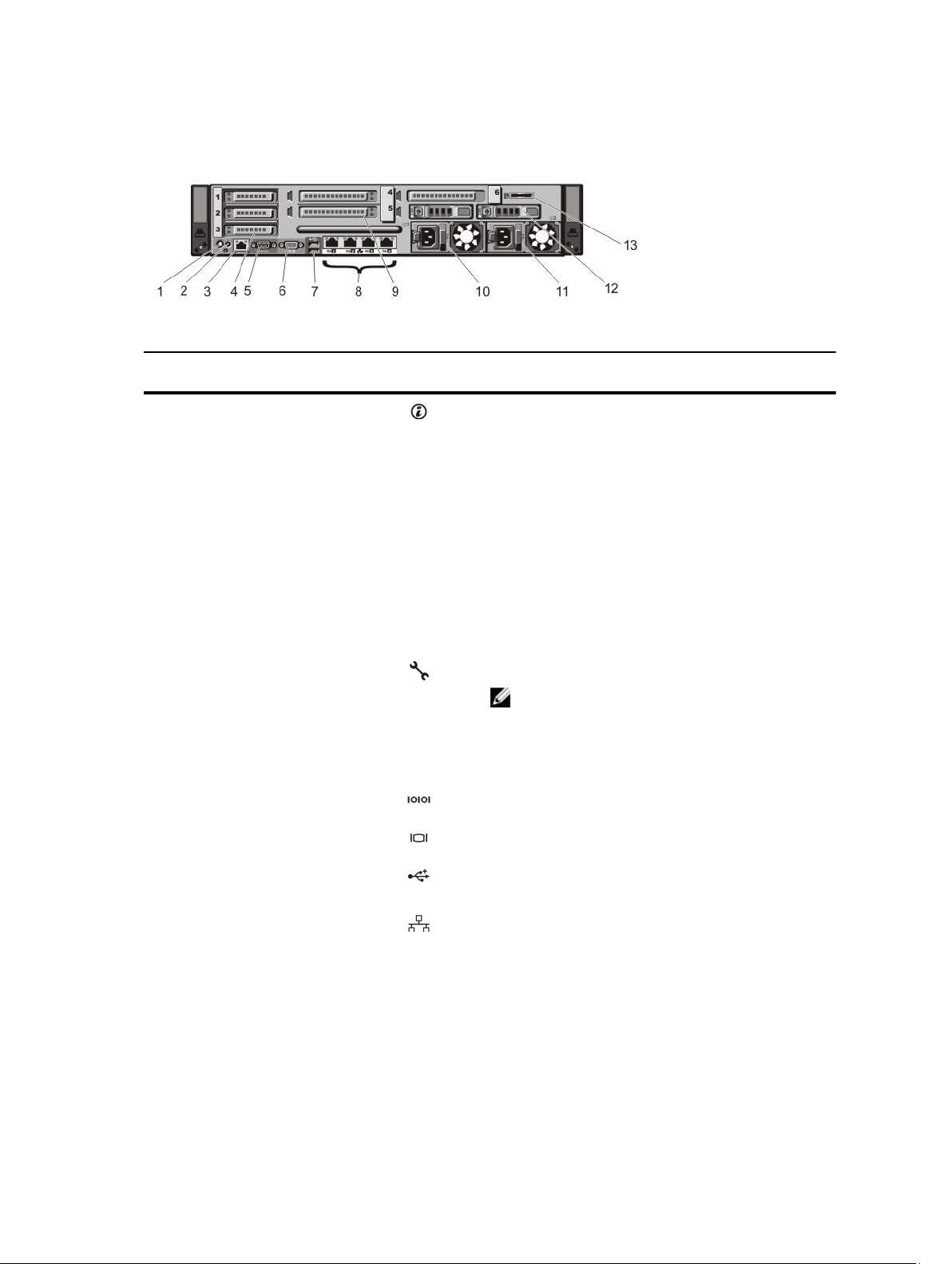
Figure 3. Back-Panel Features and Indicators
Item Indicator, Button, or
Connector
1 System identification button The identification buttons on the front and back panels
2 System identification
connector
3 iDRAC7 Enterprise port Dedicated management port.
4 PCIe expansion card slots
low–profile (3)
5 Serial connector Allows you to connect a serial device to the system.
Icon Description
can be used to locate a particular system within a rack.
When one of these buttons is pressed, the system status
indicator on the back flashes until one of the buttons is
pressed again.
Press to toggle the system ID on and off.
If the system stops responding during POST, press and
hold the system ID button for more than five seconds to
enter BIOS progress mode.
To reset iDRAC (if not disabled in F2 iDRAC setup) press
and hold the button for more than 15 seconds.
Connects the optional system status indicator assembly
through the optional cable management arm.
NOTE: The port is available for use only if the iDRAC7
Enterprise license is installed on your system.
Allows you to connect up to three PCI Express expansion
cards.
6 Video connector Allows you to connect a VGA display to the system.
7 USB connectors (2) Allows you to connect USB devices to the system. The
ports are USB 2.0-compliant.
8 Ethernet connectors (4) Four integrated 10/100/1000 Mbps NIC connectors
or
Four integrated connectors that include:
• Two 10/100/1000 Mbps NIC connectors
• Two 100 Mbps/1 Gbps/10 Gbps SFP+/10 GbE T
connectors
13

Item Indicator, Button, or
Connector
Icon Description
9 PCIe expansion card slots
full height (3)
10 Power supply (PSU1) 750 W AC
11 Power supply (PSU2) 750 W AC
12 Hard drives (2) (back) Hot-swappable 2.5 inch hard drives.
13 vFlash media card slot Allows you to insert a vFlash media card.
Allows you to connect up to three full-height PCI Express
expansion cards.
NIC Indicator Codes
Figure 4. NIC Indicator
1. link indicator
2. activity indicator
Indicator Indicator Code
Link and activity
indicators are off
Link indicator is
green
Link indicator is
amber
Activity indicator is
blinking green
The NIC is not connected to the network.
The NIC is connected to a valid network at its maximum port speed (1 Gbps or 10 Gbps).
The NIC is connected to a valid network at less than its maximum port speed.
Network data is being sent or received.
Power Indicator Codes
Each AC power supply has an illuminated translucent handle and each DC power supply (when available) has an LED
that serves as an indicator to show whether power is present or whether a power fault has occurred.
14
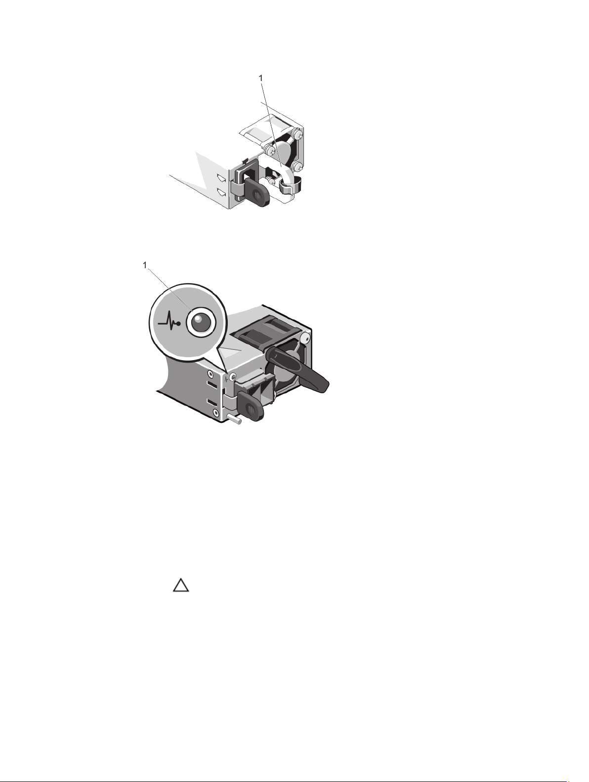
Figure 5. AC Power Supply Status Indicator
1. AC power supply status indicator/handle
Figure 6. DC Power Supply Status Indicator
1. DC power supply status indicator
Power Indicator
Condition
Pattern
Not lit Power is not connected.
Green The handle/LED indicator lights green indicating that a valid power source is connected to the
power supply and that the power supply is operational.
Flashing amber Indicates a problem with the power supply.
CAUTION: When correcting a power supply mismatch, replace only the power supply with
the flashing indicator. Swapping the opposite power supply to make a matched pair can
result in an error condition and unexpected system shutdown. To change from a High
Output configuration to a Low Output configuration or vice versa, you must power down
the system.
15

Power Indicator
Pattern
Flashing green When hot-adding a power supply, this indicates that the power supply is mismatched with the
Condition
CAUTION: AC power supplies support both 220 V and 110 V input voltages. When two
identical power supplies receive different input voltages, they can output different
wattages, and trigger a mismatch.
CAUTION: If two power supplies are used, they must be of the same type and have the
same maximum output power.
CAUTION: Combining AC and DC power supplies is not supported and triggers a mismatch.
other power supply (in terms of efficiency, feature set, health status, and supported voltage).
Replace the power supply that has the flashing indicator with a power supply that matches the
capacity of the other installed power supply.
Other Information You May Need
WARNING: See the safety and regulatory information that shipped with your system. Warranty information may be
included within this document or as a separate document.
• The
Getting Started Guide
document is available online at support.dell.com/manuals.
• The rack documentation included with your rack solution describes how to install your system into a rack, if
required.
• Any media that ships with your system that provides documentation and tools for configuring and managing your
system, including those pertaining to the operating system, system management software, system updates, and
system components that you purchased with your system.
• For the full name of an abbreviation or acronym used in this document, see the Glossary at support.dell.com/
manuals.
provides an overview of setting up your system, and technical specifications. This
NOTE: Always check for updates on support.dell.com/manuals and read the updates first because they often
supersede information in other documents.
16

Using The System Setup And Boot Manager
CAUTION: It is recommended that you make BIOS changes only during support calls with certified Dell technicians.
NOTE: Solution validation was performed using the factory shipped hardware configuration.
System Setup enables you to manage your system hardware and specify BIOS-level options.
The following keystrokes provide access to system features during startup:
Keystroke Description
<F2> Enters the System Setup.
<F10> Enters System Services, which opens the Dell Lifecycle Controller 2 (LC2). The Dell LC2
supports systems management features such as operating system deployment, hardware
diagnostics, platform updates, and platform configuration, using a graphical user interface. The
exact LC2 feature set is determined by the iDRAC license purchased. For more information, see
the Dell LC2 documentation.
<F11> Enters the BIOS Boot Manager.
<F12> Starts Preboot eXecution Environment (PXE) boot.
From the System Setup, you can:
• Change the NVRAM settings after you add or remove hardware
• View the system hardware configuration
• Enable or disable integrated devices
• Set performance and power management thresholds
• Manage system security
2
You can access the System Setup using the:
• Standard graphical browser, which is enabled by default
• Text browser, which is enabled using Console Redirection
To enable Console Redirection, in System Setup, select System BIOS → Serial Communication screen → Serial
Communication, select On with Console Redirection.
NOTE: By default, help text for the selected field is displayed in the graphical browser. To view the help text in the
text browser, press <F1>.
Entering System Setup
1. Turn on or restart your system.
2. Press <F2> immediately after you see the following message:
<F2> = System Setup
17

If your operating system begins to load before you press <F2>, allow the system to finish booting, and then restart
your system and try again.
Responding To Error Messages
If an error message is displayed while the system is booting, make a note of the message. For more information, see
System Error Messages.
NOTE: After installing a memory upgrade, it is normal for your system to display a message the first time you start
your system.
Using The System Setup Navigation Keys
Keys Action
Up arrow Moves to the previous field.
Down arrow Moves to the next field.
<Enter> Allows you to type in a value in the selected field (if applicable) or follow the link in the field.
Spacebar Expands or collapses a drop-down list, if applicable.
<Tab> Moves to the next focus area.
NOTE: For the standard graphics browser only.
<Esc> Moves to the previous page till you view the main screen. Pressing <Esc> in the main screen
displays a message that prompts you to save any unsaved changes and restarts the system.
<F1> Displays the System Setup help file.
NOTE: For most of the options, any changes that you make are recorded but do not take effect until you restart the
system.
System Setup Options
System Setup Main Screen
NOTE: Press <Alt><F> to reset the BIOS settings to default settings.
Menu Item Description
System BIOS This option is used to view and configure BIOS settings.
iDRAC Settings This option is used to view and configure iDRAC settings.
Device Settings This option is used to view and configure device settings.
System BIOS Screen
NOTE: The options for System Setup change based on the system configuration.
18

NOTE: System Setup defaults are listed under their respective options in the following sections, where applicable.
Menu Item Description
System Information Displays information about the system such as the system model name, BIOS version, Service
Tag, and so on.
Memory Settings Displays information and options related to installed memory.
Processor Settings Displays information and options related to the processor such as speed, cache size, and so
on.
Boot Settings Displays options to specify the boot mode (BIOS or UEFI). Enables you to modify UEFI and BIOS
boot settings.
NOTE: UEFI is not supported on your system.
Integrated Devices Displays options to enable or disable integrated device controllers and ports, and to specify
related features and options.
Serial Communication Displays options to enable or disable the serial ports and specify related features and options.
System Profile
Settings
System Security Displays options to configure the system security settings like, system password, setup
Miscellaneous
Settings
Displays options to change the processor power management settings, memory frequency,
and so on.
password, TPM security, and so on. It also enables or disables support for local BIOS update,
the power and NMI buttons on the system.
Displays options to change the system date, time, and so on.
System Information Screen
Menu Item Description
System Model Name Displays the system model name.
System BIOS Version Displays the BIOS version installed on the system.
System Service Tag Displays the system Service Tag.
System Manufacturer Displays the name of system manufacturer.
System Manufacturer
Contact Information
Displays the contact information of the system manufacturer.
Memory Settings Screen
Menu Item Description
System Memory Size Displays the amount of memory installed in the system.
System Memory Type Displays the type of memory installed in the system.
19

Menu Item Description
System Memory
Speed
System Memory
Voltage
Video Memory Displays the amount of video memory.
System Memory
Testing
Memory Operating
Mode
Node Interleaving If this field is Enabled, memory interleaving is supported if a symmetric memory configuration is
Serial Debug Output By default, it is set to disabled.
Displays the system memory speed.
Displays the system memory voltage.
Specifies whether system memory tests are run during system boot. Options are Enabled and
Disabled. By default, the System Memory Testing option is set to Disabled.
Specifies the memory operating mode. The options available depending on the memory
configuration of your system are Optimizer Mode, Advanced ECC Mode, Mirror Mode, Spare
Mode, and Spare with Advanced ECC Mode. By default, the Memory Operating Mode option is
set to Optimizer Mode.
NOTE: The Memory Operating Mode can have different defaults and available options
based on the memory configuration.
installed. If Disabled, the system supports Non-Uniform Memory architecture (NUMA)
(asymmetric) memory configurations. By default, Node Interleaving option is set to Disabled.
Processor Settings Screen
Menu Item Description
Logical Processor Allows you to enable or disable logical processors and display the number of logical
processors. If the Logical Processor option is set to Enabled, the BIOS displays all the logical
processors. If this option is set to Disabled, the BIOS only displays one logical processor per
core. By default, the Logical Processor option is set to Enabled.
QPI Speed Allows you to set the QuickPath Interconnect data rate settings. By default, the QPI Speed
option is set to Maximum data rate.
NOTE: The QPI speed option displays only when both the processors are installed.
Alternate RTID
(Requestor
Transaction ID)
Setting
Virtualization
Technology
Adjacent Cache Line
Prefetch
Hardware Prefetcher Allows you to enable or disable hardware prefetcher. By default, the Hardware Prefetcher
Allows you to allocate more RTIDs to the remote socket increasing cache performance
between the sockets or work in normal mode for NUMA. By default, the Alternate RTID
(Requestor Transaction ID) Setting is set to Disabled.
Allows you to enable or disable the additional hardware capabilities provided for virtualization.
By default, the Virtualization Technology option is set to Enabled.
Allows you to optimize the system for applications that require high utilization of sequential
memory access. By default, the Adjacent Cache Line Prefetch option is set to Enabled. You can
disable this option for applications that require high utilization of random memory access.
option is set to Enabled.
20

Menu Item Description
DCU Streamer
Prefetcher
DCU IP Prefetcher Allows you to enable or disable Data Cache Unit IP prefetcher. By default, the DCU IP
Execute Disable Allows you enable or disable execute disable memory protection technology. By default, the
Number of Cores per
Processor
Processor 64-bit
Support
Processor Core
Speed
Processor Bus Speed Displays the bus speed of the processors.
Processor 1
Family-ModelStepping
Allows you to enable or disable Data Cache Unit streamer prefetcher. By default, the DCU
Streamer Prefetcher option is set to Enabled.
Prefetcher option is set to Enabled.
Execute Disable option is set to Enabled.
Allows you to control the number of enabled cores in each processor. By default, the Number
of Cores per Processor option is set to All.
Specifies if the processor(s) support 64-bit extensions.
Displays the maximum core frequency of the processor.
NOTE: The processor bus speed option displays only when both the processors are
installed.
NOTE: The following settings are displayed for each processor installed in the system.
Displays the family, model and stepping of the processor as defined by Intel.
Brand Displays the brand name reported by the processor.
Level 2 Cache Displays the total L2 cache.
Level 3 Cache Displays the total L3 cache.
Number of Cores Displays the number of cores per processor.
Boot Settings Screen
Menu Item Description
Boot Mode Allows you to set the boot mode of the system.
CAUTION: Switching the boot mode may prevent the system from booting if the operating
system is not installed in the same boot mode.
By default, the Boot Mode option is set to BIOS.
Boot Sequence Retry Allows you to enable or disable the boot sequence retry feature. If this field is enabled and the
system fails to boot, the system reattempts the boot sequence after 30 seconds. By default, the
Boot Sequence Retry option is set to Disabled.
BIOS Boot Settings Allows you to enable or disable BIOS Boot options.
One-Time Boot Allows you to enable or disable a one-time boot from a selected device.
21

Integrated Devices Screen
Menu Item Description
Integrated RAID
Controller
User Accessible USB
Ports
Internal USB Port Allows you to enable or disable the internal USB port. By default, the Internal USB Port option
Internal SD Card Port Enables or disables the system’s internal SD card port. By default, Internal SD Card Port option
Internal SD Card
Redundancy
Integrated Network
Card 1
OS Watchdog Timer Allows you to enable or disable the OS watchdog timer. When this field is enabled, the
Allows you to enable or disable the integrated RAID controller. By default, the Integrated RAID
Controller option is set to Enabled.
Allows you enable or disable the user accessible USB ports. Selecting Only Back Ports On
disables the front USB ports and selecting All Ports Off disables both front and back USB ports.
By default, the User Accessible USB Ports option is set to All Ports On.
is set to On.
is set to On.
NOTE: This option is displayed only if IDSDM is installed on the system board.
If set to Mirror mode, data is written on both SD cards. If any one of the SD card fails, data is
written to the active SD card. Data from this card is copied to the replacement SD card at the
next boot. By default, Internal SD Card Redundancy option is set to Mirror.
NOTE: This option is displayed only if IDSDM is installed on the system board.
Allows you to enable or disable the integrated network card 1. By default, the Integrated
Network Card 1 option is set to Enabled.
operating system initializes the timer and the OS watchdog timer helps in recovering the
operating system. By default, the OS Watchdog Timer option is set to Disabled.
Embedded Video
Controller
SR-IOV Global Enable Allows you to enable or disable the BIOS configuration of Single Root I/O Virtualization (SR-
Slot Disablement Allows you to enable or disable available PCIe slots on your system. The Slot Disablement
22
Allows you to enable or disable the Embedded Video Controller. By default, the embedded
video controller is Enabled.
IOV) devices. By default, the SR-IOV Global Enable option is set to Disabled.
feature controls the configuration of PCIe cards installed in the specified slot.
CAUTION: Slot disablement must be used only when the installed peripheral card is
preventing booting into the Operating System or causing delays in system startup. If the
slot is disabled, both the Option ROM and UEFI driver are disabled.
NOTE: UEFI is not supported on your system.

Serial Communications Screen
Menu Item Description
Serial Communication Allows you to select serial communication devices (Serial Device 1 and Serial Device 2) in the
BIOS. BIOS console redirection can also be enabled and the port address used can be
specified. By default, Serial Communication option is set to On without Console Redirection.
Serial Port Address Allows you to set the port address for serial devices. By default, the Serial Port Address option
is set to Serial Device 1=COM2, Serial Device 2=COM1.
NOTE: Only Serial Device 2 can be used for Serial Over LAN (SOL). To use console
redirection by SOL, configure the same port address for console redirection and the serial
device.
External Serial
Connector
Failsafe Baud Rate Displays the failsafe baud rate for console redirection. The BIOS attempts to determine the
Remote Terminal
Type
Redirection After
Boot
Allows you to associate the external serial connector to serial device 1, serial device 2, or
remote access device. By default, the External Serial Connector option is set to Serial Device1.
NOTE: Only Serial Device 2 can be used for SOL. To use console redirection by SOL,
configure the same port address for console redirection and the serial device.
baud rate automatically. This failsafe baud rate is used only if the attempt fails and the value
must not be changed. By default, the Failsafe Baud Rate option is set to 11520.
Allows you to set the remote console terminal type. By default, the Remote Terminal Type
option is set to VT 100/VT 220.
Allows you to enable or disable to the BIOS console redirection when the operating system is
loaded. By default, the Redirection After Boot option is set to Enabled.
System Profile Settings Screen
Menu Item Description
System Profile Allows you to set the system profile. If you set the System Profile option to a mode other than
Custom, the BIOS automatically sets the rest of the options. You can only change the rest of the
options if the mode is set to Custom. By default, the System Profile option is set to Performance
Per Watt Optimized (DAPC). DAPC is Dell Active Power Controller.
NOTE: The following parameters are available only when the System Profile is set to
Custom.
CPU Power
Management
Memory Frequency Allows you to set the memory frequency. By default, the Memory Frequency option is set to
Turbo Boost Allows you to enable or disable the processor to operate in turbo boost mode. By default, the
Allows you to set the CPU power management. By default, the CPU Power Management option
is set to System DBPM (DAPC). DBPM is Demand-Based Power Management.
Maximum Performance.
Turbo Boost option is set to Enabled.
23

Menu Item Description
C1E Allows you to enable or disable the processor to switch to a minimum performance state when
it is idle. By default, the C1E option is set to Enabled.
C States Allows you to enable or disable the processor to operate in all available power states. By
default, the C States option is set to Enabled.
Monitor/Mwait Allows you to enable Monitor/Mwait instructions in the processor. By default, the Monitor/
Mwait option is set to Enabled for all system profiles, except Custom.
NOTE: This option can be disabled only if the C States option in Custom mode is disabled.
NOTE: When C States is enabled in Custom mode, changing the Monitor/Mwait setting
does not impact system power/performance.
Memory Patrol Scrub Allows you to set the memory patrol scrub frequency. By default, the Memory Patrol Scrub
option is set to Standard.
Memory Refresh Rate Allows you to set the memory refresh rate. By default, the Memory Refresh Rate option is set to
1x.
Memory Operating
Voltage
Allows you to set the DIMM voltage selection. When set to Auto, the system automatically sets
the system voltage to the optimal setting based on the DIMM capacity and the numbers of
DIMMs installed. By default, the Memory Operating Voltage option is set to Auto.
System Security Screen
Menu Item Description
Intel AES-NI The Intel AES-NI option improves the speed of applications by performing encryption and
decryption using the Advanced Encryption Standard Instruction Set and is set to Enabled by
default.
System Password Allows you to set the system password. This option is set to Enabled by default and is read-only
if the password jumper is not installed in the system.
Setup Password Allows you to set the setup password. This option is read-only if the password jumper is not
installed in the system.
Password Status Allows you to lock the system password. By default, the Password Status option is set to
Unlocked.
TPM Security Allows you to control the reporting mode of the Trusted Platform Module (TPM). By default, the
TPM Security option is set to Off. You can only modify the TPM Status, TPM Activation , and
Intel TXT fields if the TPM Status field is set to either On with Pre-boot Measurements or On
without Pre-boot Measurements.
TPM Activation Allows you to change the operational state of the TPM. By default, the TPM Activation option is
set to No Change.
TPM Status Displays the TPM status.
TPM Clear
24
CAUTION: Clearing the TPM results in loss of all keys in the TPM. The loss of TPM keys
may affect booting to the operating system.

Menu Item Description
Allows you to clear all the contents of the TPM. By default, the TPM Clear option is set to No.
Intel TXT Allows you enable or disable Intel Trusted Execution Technology. To enable Intel TXT,
Virtualization Technology must be enabled and TPM Security must be Enabled with Pre-boot
measurements. By default, the Intel TXT option is set to Off.
BIOS Update Control Allows you to update the BIOS using either DOS or UEFI shell-based flash utilities. For
environments that do not require local BIOS updates, it is recommended to set this field to
Disabled. By default, the BIOS Update Control option is set to Unlocked.
NOTE: BIOS updates using Dell Update Package are not affected by this option.
NOTE: UEFI is not supported on your system.
Power Button Allows you to enable or disable the power button on the front of the system. By default, the
Power Button option is set to Enabled.
NMI Button Allows you to enable or disable the NMI button on the front of the system. By default, the NMI
Button option is set to Disabled.
AC Power Recovery Allows you to set how the system reacts after AC power is restored to the system. By default,
the AC Power Recovery option is set to Last.
AC Power Recovery
Delay
User Defined Delay
(60s to 240s)
Allows you to set how the system supports staggering of power up after AC power is restored
to the system. By default, the AC Power Recovery Delay option is set to Immediate.
Allows you to set the User Defined Delay when the User Defined option for AC Power Recovery
Delay is selected.
Miscellaneous Settings
Menu Item Description
System Time Allows you to set the time on the system.
System Date Allows you to set the date on the system.
Asset Tag Displays the asset tag and allows you to modify it for security and tracking purposes.
Keyboard NumLock Allows you to set whether the system boots with the NumLock enabled or disabled. By default
the Keyboard NumLock is set to On.
NOTE: This field does not apply to 84-key keyboards.
Report Keyboard
Errors
F1/F2 Prompt on Error Allows you to enable or disable the F1/F2 prompt on error. By default, F1/F2 Prompt on Error is
In-System
Characterization
Allows you to set whether keyboard-related error messages are reported during system boot.
By default, the Report Keyboard Errors field is set to Report.
set to Enabled.
This field enables or disables In-System Characterization. By default, In-System
Characterization is set to Enabled.
25

System And Setup Password Features
You can create a system password and a setup password to secure your system. To enable creation of the system and
setup password, the password jumper must be set to enabled. For more information on the password jumper settings,
see System Board Jumper Settings.
System password This is the password that you must enter to log on to your system.
Setup password This is the password that you must enter to access and make changes to the BIOS settings of
your system.
CAUTION: The password features provide a basic level of security for the data on your system.
CAUTION: Anyone can access the data stored on your system if the system is running and unattended.
NOTE: Your system is shipped with the system and setup password feature disabled.
Assigning A System And/Or Setup Password
NOTE: The password jumper enables or disables the System Password and Setup Password features. For more
information on the password jumper settings, see System Board Jumper Settings.
You can assign a new System Password and/or Setup Password or change an existing System Password and/or Setup
Password only when the password jumper setting is enabled and Password Status is Unlocked. If the Password Status
is Locked, you cannot change the System Password and/or Setup Password.
If the password jumper setting is disabled, the existing System Password and Setup Password is deleted and you need
not provide the system password to log on to the system.
To assign a system and/or setup password:
1. To enter System Setup, press <F2> immediately after a power-on or reboot.
2. In the System Setup Main Menu, select System BIOS and press <Enter>.
The System BIOS screen is displayed.
3. In the System BIOS screen, select System Security and press <Enter>.
The System Security screen is displayed.
4. In the System Security screen, verify that Password Status is Unlocked.
5. Select System Password , enter your system password, and press <Enter> or <Tab>.
Use the following guidelines to assign the system password:
– A password can have up to 32 characters.
– The password can contain the numbers 0 through 9.
– Only lower case letters are valid, upper case letters are not allowed.
– Only the following special characters are allowed: space, (”), (+), (,), (-), (.), (/), (;), ([), (\), (]), (`).
A message prompts you to re-enter the system password.
6. Re-enter the system password that you entered earlier and click OK.
7. Select Setup Password, enter your system password and press <Enter> or <Tab>.
A message prompts you to re-enter the setup password.
8. Re-enter the setup password that you entered earlier and click OK.
26

9. Press <Esc> to return to the System BIOS screen. Press <Esc> again, and a message prompts you to save the
changes.
NOTE: Password protection does not take effect until the system reboots.
Deleting Or Changing An Existing System And/Or Setup Password
Ensure that the Password jumper is set to enabled and the Password Status is Unlocked before attempting to delete or
change the existing System and/or Setup password. You cannot delete or change an existing System or Setup password
if the Password Status is Locked.
To delete or change the existing System and/or Setup password:
1. To enter System Setup, press <F2> immediately after a power-on or reboot.
2. In the System Setup Main Menu, select System BIOS and press <Enter>.
The System BIOS screen is displayed.
3. In the System BIOS Screen, select System Security and press <Enter>.
The System Security screen is displayed.
4. In the System Security screen, verify that Password Status is Unlocked.
5. Select System Password, alter or delete the existing system password and press <Enter> or <Tab>.
6. Select Setup Password, alter or delete the existing setup password and press <Enter> or <Tab>.
NOTE: If you change the System and/or Setup password a message prompts you to re-enter the new
password. If you delete the System and/or Setup password, a message prompts you to confirm the deletion.
7. Press <Esc> to return to the System BIOS screen. Press <Esc> again, and a message prompts you to save the
changes.
NOTE: You can disable password security while logging on to the system. To disable the password security, turn on
or reboot your system, type your password and press <Ctrl><Enter>.
Using Your System Password To Secure Your System
NOTE: If you have assigned a setup password, the system accepts your setup password as an alternate system
password.
1. Turn on or reboot your system.
2. Type your password and press <Enter>.
When Password Status is Locked, type the password and press <Enter> when prompted at reboot.
If an incorrect system password is entered, the system displays a message and prompts you to re-enter your password.
You have three attempts to enter the correct password. After the third unsuccessful attempt, the system displays an
error message that the system has halted and must be powered down.
Even after you shut down and restart the system, the error message is displayed until the correct password is entered.
NOTE: You can use the Password Status option in conjunction with the System Password and Setup Password
options to protect your system from unauthorized changes.
Operating With A Setup Password Enabled
If Setup Password is Enabled, enter the correct setup password before modifying most of the System Setup options.
27

If you do not enter the correct password in three attempts, the system displays the message
Invalid Password! Number of unsuccessful password attempts: <x> System Halted!
Must power down.
Even after you shut down and restart the system, the error message is displayed until the correct password is entered.
The following options are exceptions:
• If System Password is not Enabled and is not locked through the Password Status option, you can assign a
system password.
• You cannot disable or change an existing system password.
NOTE: You can use the Password Status option in conjunction with the Setup Password option to protect the
system password from unauthorized changes.
Embedded System Management
The Dell Lifecycle Controller provides advanced embedded systems management throughout the server’s lifecycle. The
Lifecycle Controller can be started during the boot sequence and can function independently of the operating system.
NOTE: Certain platform configurations may not support the full set of features provided by the Lifecycle Controller.
For more information about setting up the Lifecycle Controller, configuring hardware and firmware, and deploying the
operating system, see the Lifecycle Controller documentation at support.dell.com/manuals.
28

Installing System Components
NOTE: Solution validation was performed using the factory shipped hardware configuration.
Recommended Tools
You may need the following items to perform the procedures in this section:
• Key to the system keylock
• #2 Phillips screwdriver
• T10 and T15 Torx screwdrivers
• Wrist grounding strap connected to ground
Following tools are required for assembling cables for a DC power supply unit (PSU), when available:
• AMP 90871-1 hand-crimping tool or equivalent
• Wire-stripper pliers capable of removing insulation from size 10 AWG solid or stranded, insulated copper wire
NOTE: Use alpha wire part number 3080 or equivalent (65/30 stranding).
Front Bezel (Optional)
3
Removing The Front Bezel
1. Unlock the keylock at the left end of the bezel.
2. Lift the release latch next to the keylock.
3. Rotate the left end of the bezel away from the front panel.
4. Unhook the right end of the bezel and pull the bezel away from the system.
29
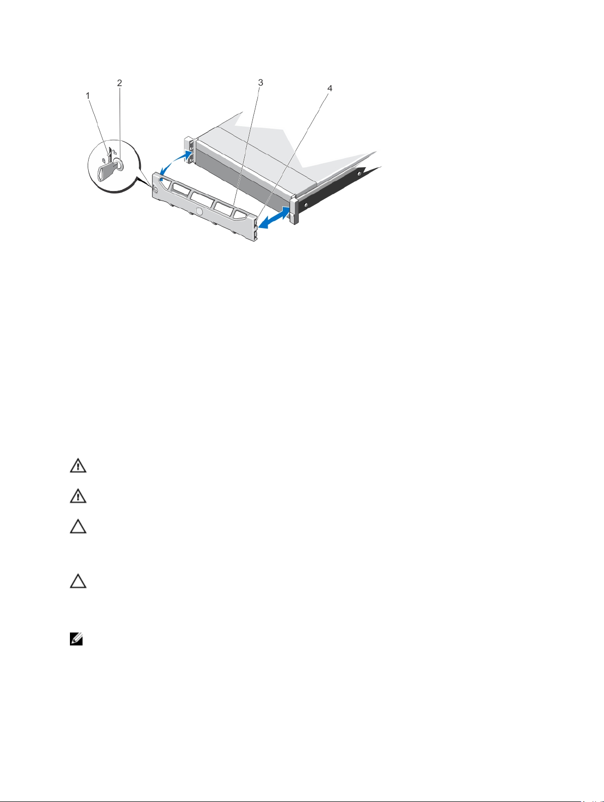
Figure 7. Removing and Installing the Front Bezel
1. release latch
2. keylock
3. front bezel
4. locking hook
Installing The Front Bezel
1. Hook the right end of the bezel onto the chassis.
2. Fit the free end of the bezel onto the system.
3. Secure the bezel with the keylock.
Opening And Closing The System
WARNING: Whenever you need to lift the system, get others to assist you. To avoid injury, do not attempt to lift the
system by yourself.
WARNING: Opening or removing the system cover when the system is on may expose you to a risk of electric
shock.
CAUTION: Many repairs may only be done by a certified service technician. You should only perform
troubleshooting and simple repairs as authorized in your product documentation, or as directed by the online or
telephone service and support team. Damage due to servicing that is not authorized by Dell is not covered by your
warranty. Read and follow the safety instructions that came with the product.
CAUTION: Do not operate the system without the cover for a duration exceeding five minutes.
Opening The System
NOTE: It is recommended that you always use a static mat and static strap while working on components in the
interior of the system.
1. Turn off the system and attached peripherals, and disconnect the system from the electrical outlet.
2. Rotate the latch release lock counter clockwise to the unlocked position.
30
 Loading...