

Dell PowerEdge R415 User Manual

Dell PowerEdge R415 Systems
Hardware Owner’s
Manual
Regulatory Model E07S Series
Regulatory Type E07S003

Notes, Cautions, and Warnings
NOTE: A NOTE indicates important information that helps you make better use of
your computer.
CAUTION: A CAUTION indicates potential damage to hardware or loss of data if
instructions are not followed.
WARNING: A WARNING indicates a potential for property damage, personal
injury, or death.
____________________
Information in this publication is subject to change without notice.
© 2010 Dell Inc. All rights reserved.
Reproduction of these materials in any manner whatsoever without the written permission of Dell Inc.
is strictly forbidden.
Trademarks used in this text: Dell™, the DELL logo, and PowerEdge™ are trademarks of Dell Inc.
Microsoft
trademarks of Microsoft Corporation in the United States and/or other countries.
Other trademarks and trade names may be used in this publication to refer to either the entities claiming
the marks and names or their products. Dell Inc. disclaims any proprietary interest in trademarks and
trade names other than its own.
August 2010 Rev. A00
®
, Windows®, MS-DOS®, and Windows Server® are either trademarks or registered

Contents
1 About Your System. . . . . . . . . . . . . . . . . . . 9
Accessing System Features During Startup. . . . . . . . 9
Front-Panel Features and Indicators
. . . . . . . . . . 10
LCD Panel Features (Optional). . . . . . . . . . . . . . 12
Hard-Drive Indicator Patterns
Back-Panel Features and Indicators
. . . . . . . . . . . . . . 16
. . . . . . . . . . 17
Guidelines for Connecting External Devices . . . . . . 19
NIC Indicator Codes
Power Indicator Codes
Diagnostic Lights (Optional)
. . . . . . . . . . . . . . . . . . . 19
. . . . . . . . . . . . . . . . . 20
. . . . . . . . . . . . . . . 21
LCD Status Messages . . . . . . . . . . . . . . . . . . 24
System Messages
Warning Messages
. . . . . . . . . . . . . . . . . . . . 40
. . . . . . . . . . . . . . . . . . . 54
Diagnostics Messages . . . . . . . . . . . . . . . . . 54
Alert Messages
Other Information You May Need
. . . . . . . . . . . . . . . . . . . . . 54
. . . . . . . . . . . . 55
Contents 3

2 Using the System Setup Program and
UEFI Boot Manager . . . . . . . . . . . . . . . . . 57
Choosing the System Boot Mode . . . . . . . . . . . . 57
Entering the System Setup Program
System Setup Options
. . . . . . . . . . . . . . . . . . 59
. . . . . . . . . . . 58
Entering the UEFI Boot Manager. . . . . . . . . . . . . 70
System and Setup Password Features
Embedded System Management
. . . . . . . . . . 72
. . . . . . . . . . . . . 76
Baseboard Management Controller Configuration . . . 76
iDRAC6 Configuration Utility
. . . . . . . . . . . . . . . 77
3 Installing System Components . . . . . . . 79
Recommended Tools . . . . . . . . . . . . . . . . . . . 79
Inside the System
Front Bezel (Optional) . . . . . . . . . . . . . . . . . . 81
Opening and Closing the System
Hard Drives
. . . . . . . . . . . . . . . . . . . . . 79
. . . . . . . . . . . . 82
. . . . . . . . . . . . . . . . . . . . . . . . 84
4 Contents
Optical Drive . . . . . . . . . . . . . . . . . . . . . . . 92
Power Supplies
Expansion Card and Expansion-Card Riser
Integrated Storage Controller Card
Expansion-Card Riser
. . . . . . . . . . . . . . . . . . . . . 95
. . . . . . . 99
. . . . . . . . . . 103
. . . . . . . . . . . . . . . . . 105

Internal USB Memory Key . . . . . . . . . . . . . . . . 107
System Board Shroud
Power Distribution Board Shroud
. . . . . . . . . . . . . . . . . . 109
. . . . . . . . . . . . 111
iDRAC6 Express Card (Optional). . . . . . . . . . . . . 112
iDRAC6 Enterprise Card (Optional)
VFlash Media (Optional)
. . . . . . . . . . . . . . . . . 116
. . . . . . . . . . . 114
Cooling Fans . . . . . . . . . . . . . . . . . . . . . . . 117
RAID Battery (Optional)
System Memory
. . . . . . . . . . . . . . . . . 119
. . . . . . . . . . . . . . . . . . . . . 121
Processors . . . . . . . . . . . . . . . . . . . . . . . . 127
System Battery
Control Panel Assembly
SAS Backplane
. . . . . . . . . . . . . . . . . . . . . . 133
. . . . . . . . . . . . . . . . . 135
. . . . . . . . . . . . . . . . . . . . . 140
Power Distribution Board . . . . . . . . . . . . . . . . 142
System Board
. . . . . . . . . . . . . . . . . . . . . . 144
4 Troubleshooting Your System . . . . . . . . 149
Safety First—For You and Your System . . . . . . . . . 149
Troubleshooting System Startup Failure
Troubleshooting External Connections
Troubleshooting the Video Subsystem
Troubleshooting a USB Device
. . . . . . . . . . . . . 150
. . . . . . . . 149
. . . . . . . . . 150
. . . . . . . . . 150
Contents 5

Troubleshooting a Serial I/O Device. . . . . . . . . . 151
Troubleshooting a NIC
Troubleshooting a Wet System
. . . . . . . . . . . . . . . . . 151
. . . . . . . . . . . . . 152
Troubleshooting a Damaged System. . . . . . . . . . 154
Troubleshooting the System Battery
Troubleshooting Power Supplies
. . . . . . . . . . 155
. . . . . . . . . . . 155
Troubleshooting System Cooling Problems . . . . . . 156
Troubleshooting a Fan
Troubleshooting System Memory
. . . . . . . . . . . . . . . . . 156
. . . . . . . . . . . 157
Troubleshooting an Internal USB Key . . . . . . . . . 159
Troubleshooting an SD Card
Troubleshooting an Optical Drive
Troubleshooting an External Tape Drive
. . . . . . . . . . . . . . 160
. . . . . . . . . . . 161
. . . . . . . . 162
Troubleshooting a Hard Drive . . . . . . . . . . . . . 163
Troubleshooting a Storage Controller
. . . . . . . . . 164
5 Running the System Diagnostics . . . . . . 169
6 Contents
Troubleshooting Expansion Cards
. . . . . . . . . . . 165
Troubleshooting the Processors . . . . . . . . . . . . 166
Using Dell Diagnostics. . . . . . . . . . . . . . . . . 169
Embedded System Diagnostics Features
When to Use the Embedded System Diagnostics
. . . . . . . 169
. . . 170

Running the Embedded System Diagnostics . . . . . . 170
System Diagnostics Testing Options
Using the Custom Test Options
. . . . . . . . . . 170
. . . . . . . . . . . . . 171
6 Jumpers and Connectors . . . . . . . . . . . 173
System Board Jumpers . . . . . . . . . . . . . . . . . 173
System Board Connectors
SAS Backplane Board Connectors
. . . . . . . . . . . . . . . . 174
. . . . . . . . . . . 176
Expansion-Card Riser-Board
Components and PCIe Buses
. . . . . . . . . . . . . . 177
Power Distribution Board Connectors . . . . . . . . . 178
Disabling a Forgotten Password
. . . . . . . . . . . . 179
7 Getting Help. . . . . . . . . . . . . . . . . . . . . . 181
Contacting Dell . . . . . . . . . . . . . . . . . . . . . 181
Index . . . . . . . . . . . . . . . . . . . . . . . . . . . . . . 183
Contents 7

8 Contents

1
About Your System
Accessing System Features During Startup
The following keystrokes provide access to system features during startup.
Keystroke Description
<F2> Enters the System Setup program. See "Using the System Setup
Program and UEFI Boot Manager" on page 57.
<F10> Enters System Services, which opens the Lifecycle Controller.
The Lifecycle Controller allows you to access utilities such as
embedded system diagnostics. For more information, see the
Lifecycle Controller documentation at support.dell.com/manuals.
<F11> Enters the BIOS Boot Manager or the UEFI Boot Manager,
depending on the system’s boot configuration. See "Using the System
Setup Program and UEFI Boot Manager" on page 57.
<F12> Starts PXE boot.
<Ctrl><E> Enters the Baseboard Management Controller (BMC) or iDRAC6
Configuration Utility, which allows access to the System Event Log
(SEL) and configuration of remote access to the system. For more
information, see the BMC or iDRAC user documentation at
support.dell.com/manuals.
<Ctrl><C> Enters the SAS Configuration Utility. For more information, see the
SAS adapter documentation at support.dell.com/manuals.
<Ctrl><R> Enters the PERC configuration utility. For more information, see the
PERC card documentation at support.dell.com/manuals.
<Ctrl><S> Enters the utility to configure NIC settings for PXE boot. For more
information, see the documentation for your integrated NIC at
support.dell.com/manuals.
About Your System 9
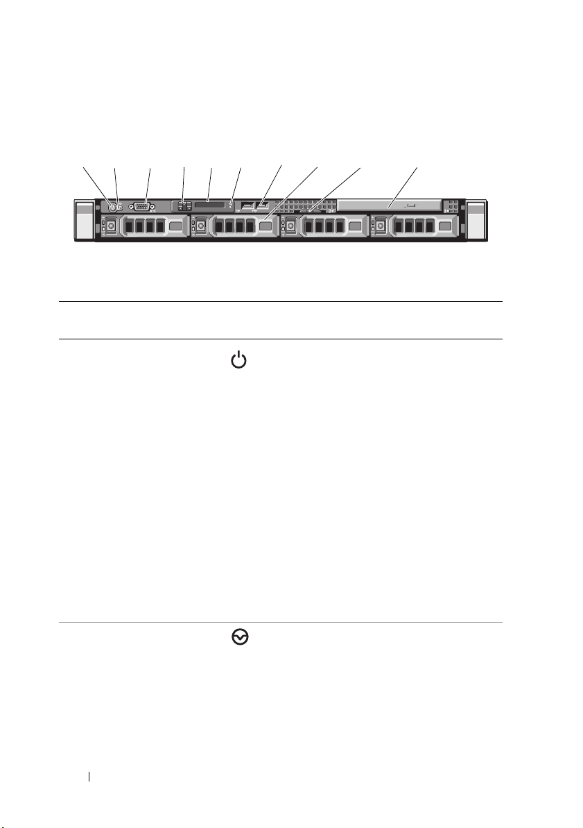
Front-Panel Features and Indicators
1 2
34
5
7
8
9
6
10
Figure 1-1. Front-Panel Features and Indicators
Item Indicator, Button, or
Connector
1Power-on indicator,
power button
Icon Description
The power-on indicator lights when the
system power is on.
The power button controls the
DC power supply output to the system.
When the optional system bezel is
installed, the power button is not
accessible.
NOTE: When powering on the system,
the video monitor can take from several
seconds to over 2 minutes to display an
image, depending on the amount of
memory installed in the system.
NOTE: On ACPI-compliant operating
systems, turning off the system using the
power button causes the system to
perform a graceful shutdown before
power to the system is turned off.
2 NMI button Used to troubleshoot software and
device driver errors when using certain
operating systems. This button can be
pressed using the end of a paper clip.
Use this button only if directed to do so
by qualified support personnel or by the
operating system's documentation.
10 About Your System

Item Indicator, Button, or
Connector
3 Video connector Connects a monitor to the system.
4 LCD menu buttons Allows you to navigate the control panel
5LED or LCD panel
Icon Description
LCD menu.
NOTE: Depending on the configuration,
your system may have either LED
diagnostic indicators or an LCD panel.
LED panel: The four diagnostic
indicator lights display error codes
during system startup. See "Diagnostic
Lights (Optional)" on page 21.
LCD panel: Provides system ID, status
information, and system error messages.
The LCD lights during normal system
operation. Both the systems management
software and the identification buttons
located on the front and back of the
system can cause the LCD to flash blue
to identify a particular system.
The LCD lights amber when the system
needs attention, and the LCD panel
displays an error code followed by
descriptive text.
NOTE: If the system is connected to
AC power and an error has been
detected, the LCD lights amber
regardless of whether the system
has been powered on.
6 System identification
button
The identification buttons on the front
and back panels can be used to locate
a particular system within a rack.
When one of these buttons is pushed,
the LCD panel on the front and the blue
system status indicator on the back blink
until one of the buttons is pushed again.
About Your System 11

Item Indicator, Button, or
Connector
7 USB connectors (2) Connects USB devices to the system.
8 hard-drives (4) Up to four 2.5-inch in 3.5-inch HDD hot
9 System identification
panel
10 Optical drive One optional slim-line SATA
Icon Description
The ports are USB 2.0-compliant.
swap carrier or up to four 3.5-inch
cabled/hot swap.
A slide-out panel for system information
including the Express Service tag,
embedded NIC MAC address, and
iDRAC6 Enterprise card MAC address.
Space is provided for an additional label.
DVD-ROM drive or DVD+/-RW drive.
NOTE: DVD devices are data only.
LCD Panel Features (Optional)
The system's LCD panel provides system information and status and error
messages to signify when the system is operating correctly or when the system
needs attention. See "LCD Status Messages" on page 24 for information
about specific status codes.
The LCD backlight lights blue during normal operating conditions and lights
amber to indicate an error condition. When the system is in standby mode,
the LCD backlight is off and can be turned on by pressing the Select button
on the LCD panel. The LCD backlight will remain off if LCD messaging is
turned off through the BMC or iDRAC6 utility, the LCD panel, or other
tools.
12 About Your System
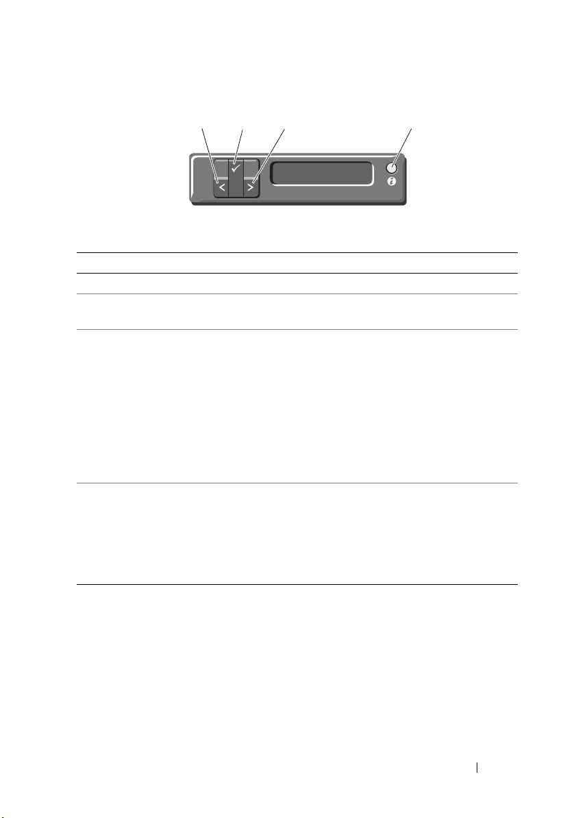
Figure 1-2. LCD Panel Features
1
2
4
3
Item Buttons Description
1 Left Moves the cursor back in one-step increments.
2 Select Selects the menu item highlighted by the
cursor.
3 Right Moves the cursor forward in one-step
increments.
During message scrolling:
• Press once to increase scrolling speed.
• Press again to stop.
• Press again to return to default scrolling
speed.
• Press again to repeat the cycle.
4 System identification Turns the system ID mode on (LCD panel
flashes blue) and off.
Press quickly to toggle the system ID on and
off. If the system hangs during POST, press and
hold the system ID button for more than
five seconds to enter BIOS Progress mode.
Home Screen
The Home screen displays user-configurable information about the system.
This screen is displayed during normal system operation when there are no
status messages or errors present. When the system is in standby mode,
the LCD backlight will turn off after five minutes of inactivity if there are
no error messages. Press one of the three navigation buttons (Select, Left,
or Right) to view the Home screen.
About Your System 13

To navigate to the Home screen from another menu, continue to select the
up arrow until the Home icon is displayed, and then select the
Home icon.
From the Home screen, press the Select button to enter the main menu.
See the following tables for information on the Setup and View submenus.
Setup Menu
NOTE: When you select an option in the Setup menu, you must confirm the option
before proceeding to the next action.
Option Description
BMC or DRAC
NOTE: If an iDRAC6 Express
card is installed on the
system, the BMC option is
replaced by DRAC.
Set error Select SEL to display LCD error messages in a format
Set home Select the default information to be displayed on the
Select DHCP or Static IP to configure the network
mode. If Static IP is selected, the available fields are IP,
Subnet (Sub), and Gateway (Gtw). Select Setup DNS
to enable DNS and to view domain addresses.
Two separate DNS entries are available.
that matches the IPMI description in the SEL. This can
be useful when trying to match an LCD message with
an SEL entry.
Select Simple to display LCD error messages in a
simplified user-friendly format. See "LCD Status
Messages" on page 24 for a list of messages in this
format.
LCD Home screen. See "View Menu" on page 15 to see
the options and option items that can be selected to
display by default on the Home screen.
14 About Your System

View Menu
Option Description
BMC IP or DRAC IP
NOTE: If an iDRAC6 Express
card is installed on the
system, the BMC IP option is
replaced by DRAC IP.
MAC Displays the MAC addresses for DRAC, iSCSIn, or
Name Displays the name of the Host, Model, or User String
Number Displays the Asset tag or the Service tag for the system.
Power Displays the power output of the system in BTU/hr or
Temperature Displays the temperature of the system in Celsius or
Displays the IPv4 or IPv6 addresses for the iDRAC6.
Addresses include DNS (Primary and Secondary),
Gateway, IP, and Subnet (IPv6 does not have Subnet).
NOTE: BMC IP supports only IPv4 addresses.
NETn.
NOTE: If the iDRAC6 Express card is not installed on the
system, the MAC option displays the MAC addresses for
BMC, iSCSIn, or NETn.
for the system.
Watts. The display format can be configured in the
Set home submenu of the Setup menu. See "Setup
Menu" on page 14.
Fahrenheit. The display format can be configured in the
"Set home" submenu of the Setup menu (see "Setup
Menu" on page 14).
About Your System 15
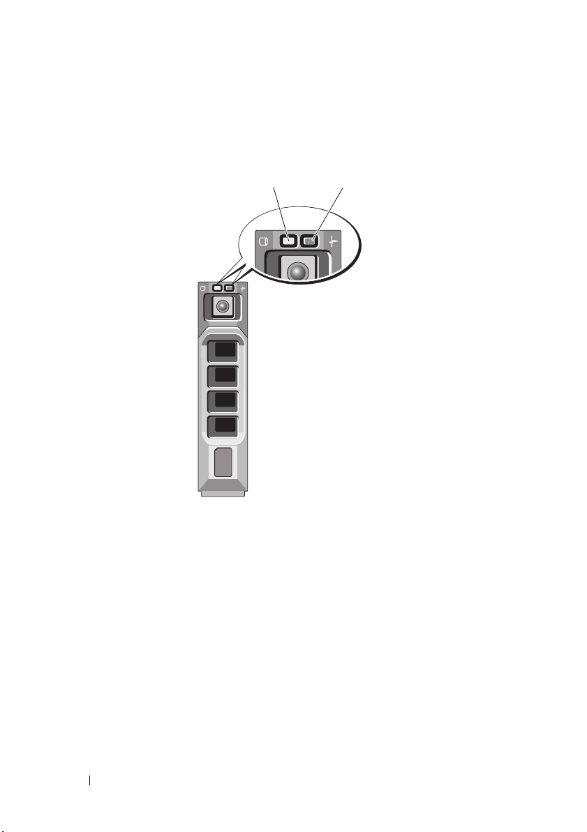
Hard-Drive Indicator Patterns
1
2
Figure 1-3. Hard-Drive Indicators
1 hard-drive activity indicator
(green)
16 About Your System
2 hard-drive status indicator
(green and amber)

Drive-Status Indicator Pattern (RAID Only) Condition
2
1
3
46
9
10
11
12
8
7
5
Blinks green two times per second Identify drive/preparing for removal
Off Drive ready for insertion or removal
NOTE: The drive status indicator remains
off until all hard-drives are initialized after
system power is applied. Drives are not
ready for insertion or removal during this
time.
Blinks green, amber, and off Drive predicted failure
Blinks amber four times per second Drive failed
Blinks green slowly Drive rebuilding
Steady green Drive online
Blinks green three seconds, amber three
seconds, and off six seconds.
Rebuild aborted
Back-Panel Features and Indicators
Figure 1-4. Back-Panel Features and Indicators
Item Indicator, Button, or
Connector
1 serial connector Connects a serial device to the system.
2 video connector Connects a VGA display to the system.
3 VFlash media slot
(optional)
Icon Description
Connects an external SD memory card
for the optional iDRAC6 Enterprise card.
About Your System 17
Item Indicator, Button, or
Connector
4 iDRAC6 Enterprise port
(optional)
5 USB connectors (2) Connects USB devices to the system.
6 Ethernet connectors (2) Embedded 10/100/1000 NIC
7 PCIe slot 1 PCI Express (Generation 2) x16-wide
8Active ID CMA
connector
9 System status indicator Lights blue during normal
10 System identification
button
11 Power supply 1(PS1) 500 W power supply (redundant).
12 Power supply 2(PS2) 500 W power supply (redundant) or
Icon Description
Dedicated management port for the
optional iDRAC6 Enterprise card.
The ports are USB 2.0-compliant.
connectors.
expansion slot (full-height,
half-length).
Connector for attaching a system
indicator extension cable that is used
on a cable management arm.
system operation.
Lights amber when the system needs
attention due to a problem.
The identification buttons on the front
and back panels can be used to locate a
particular system within a rack. When
one of these buttons is pushed, the
LCD panel on the front and the system
status indicator on the chassis back
panel light blue until one of the
buttons is pushed again.
480 W power supply (non-redundant).
18 About Your System
Guidelines for Connecting External Devices
1
2
• Turn off power to the system and external devices before attaching a new
external device. Turn on any external devices before turning on the system
(unless the documentation for the device specifies otherwise).
• Ensure that the appropriate driver for the attached device has been
installed on the system.
• If necessary to enable ports on your system, use the System Setup program.
S
ee "Using the System Setup Program and UEFI Boot Manager" on
page 57.
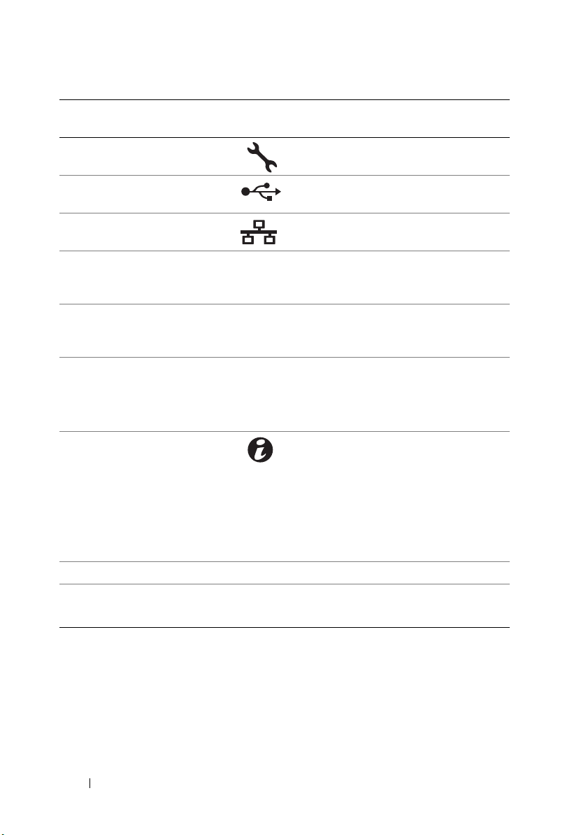
NIC Indicator Codes
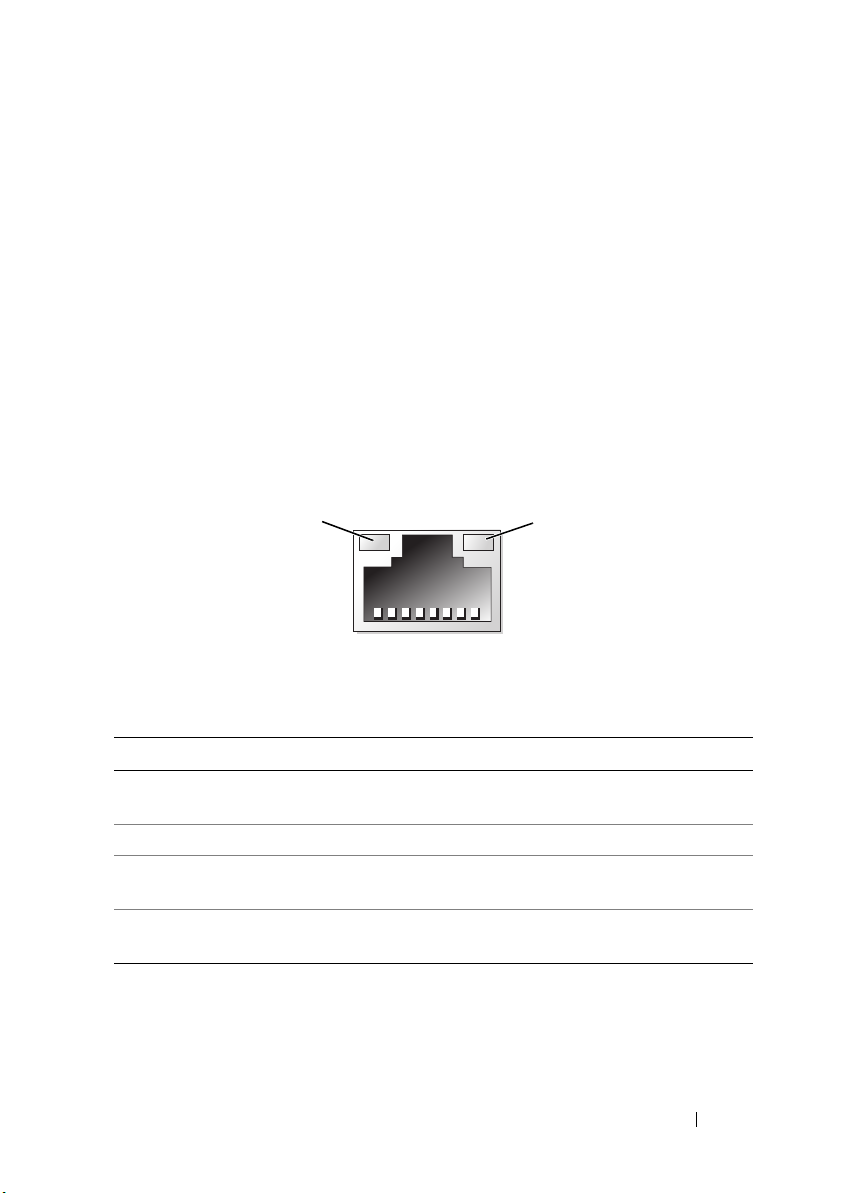
Figure 1-5. NIC Indicators
1 link indicator 2 activity indicator
Indicator Indicator Code
Link and activity
indicators are off
Link indicator is green The NIC is connected to a valid link at 1000 Mbps.
Link indicator is amber The NIC is connected to a valid network link at 10/100
Activity indicator is green
blinking
The NIC is not connected to the network.
Mbps.
Network data is being sent or received.
About Your System 19

Power Indicator Codes
The power supplies have indicators that show whether power is present or
whether a power fault has occurred.
• Not lit—AC power is not connected.
• Green—In standby mode, a green light indicates that a valid AC source is
connected to the power supply and that the power supply is operational.
When the system is on, a green light also indicates that the power supply is
providing DC power to the system.
• Amber—Indicates a problem with the power supply.
• Alternating green and amber—When hot-adding a power supply, this
indicates that the power supply is mismatched with the other power
supply (a high output power supply and an Energy Smart power supply are
installed in the same system). Replace the power supply that has the
flashing indicator with a power supply that matches the capacity of the
other installed power supply.
CAUTION: When correcting a power supply mismatch, replace only the power
supply with the flashing indicator. Swapping the opposite power supply to make a
matched pair can result in an error condition and unexpected system shutdown.
To change from a High Output configuration to an Energy Smart configuration or
vice versa, you must power down the system.
20 About Your System
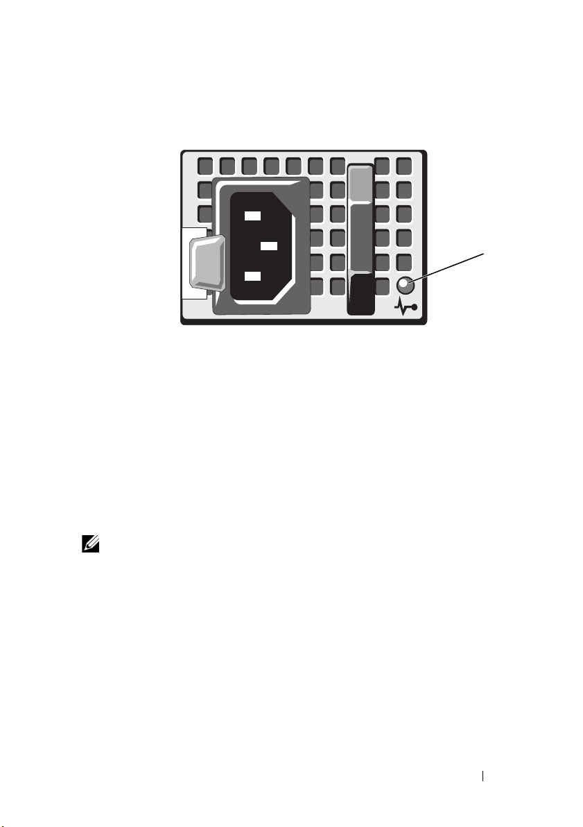
Figure 1-6. Power Supply Status Indicator
1
1 power supply status indicator
Diagnostic Lights (Optional)
The four diagnostic indicator lights on the system front panel display error
codes during system startup. Table 1-1 lists the causes and possible corrective
actions associated with these codes. A highlighted circle indicates the light is
on; a non-highlighted circle indicates the light is off.
NOTE: The diagnostic LEDs are not present when the system is equipped with an
LCD display.
About Your System 21
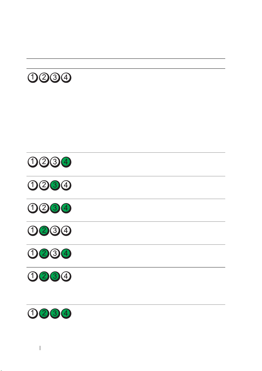
Table 1-1. Diagnostic Indicator Codes (Optional)
Code Causes Corrective Action
The system is in a normal
off condition or a possible
pre-BIOS failure has
occurred.
The diagnostic lights are
not lit after the system
successfully boots to the
operating system.
The system is in a normal
operating condition after
POST.
BIOS checksum failure
detected; system is in
recovery mode.
Possible processor failure. See "Troubleshooting the
Memory failure. See "Troubleshooting System
Plug the system into a working
electrical outlet and press the
power button.
Information only.
See "Getting Help" on page 181.
Processors" on page 166.
Memory" on page 157.
Possible expansion card
failure.
Possible video failure. See "Getting Help" on page 181.
Hard drive failure. Ensure that the diskette drive and
Possible USB failure. See "Troubleshooting a USB
22 About Your System
See "Troubleshooting Expansion
Cards" on page 165.
hard-drive are properly
connected. See "Hard Drives" on
page 84 for information on the
drives installed in your system.
Device" on page 150.
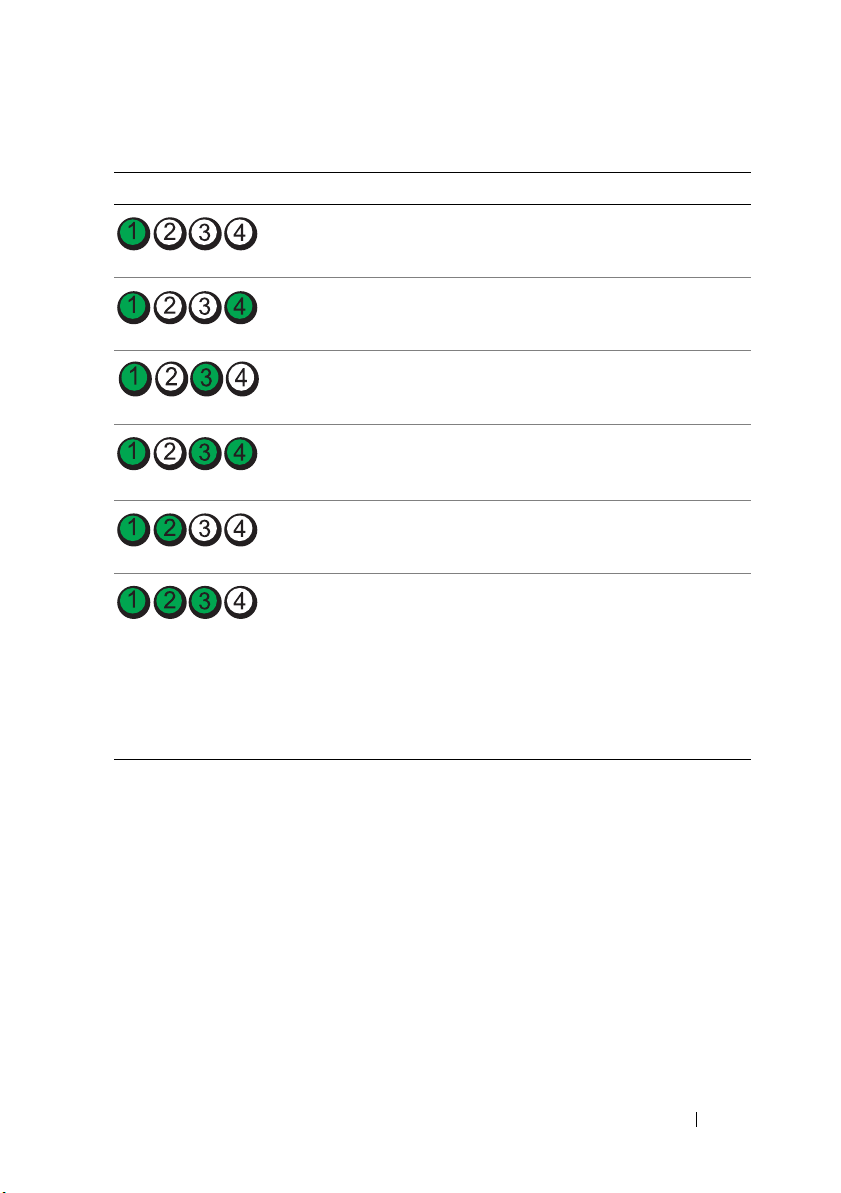
Table 1-1. Diagnostic Indicator Codes (Optional)
Code Causes Corrective Action
No memory modules
detected.
System board failure. See "Getting Help" on page 181.
(continued)
See "Troubleshooting System
Memory" on page 157.
Memory configuration
error.
Possible system board
resource and/or system
board hardware failure.
Possible system resource
configuration error.
Other failure. Ensure that the diskette drive,
See "Troubleshooting System
Memory" on page 157.
See "Getting Help" on page 181.
See "Getting Help" on page 181.
optical drive, and hard-drives are
properly connected. See
"Troubleshooting Your System"
on page 149 for the appropriate
drive installed in your system. If
the problem persists, see "Getting
Help" on page 181.
About Your System 23

LCD Status Messages
The LCD messages consist of brief text messages that refer to events
recorded in the System Event Log (SEL). For information on the SEL and
configuring system management settings, see the OpenManage Server
Administrator documentation at support.dell.com/manuals.
NOTE: If your system fails to boot, press the System ID button for at least five
seconds until an error code appears on the LCD. Record the code, then see "Getting
Help" on page 181.
Viewing Status Messages
If a system error occurs, the LCD screen will turn amber. Press the Select
button to view the list of errors or status messages. Press the left and right
buttons to highlight an error number, and press Select to view the error.
Removing LCD Status Messages
For faults associated with sensors, such as temperature, voltage, fans, and so
on, the LCD message is automatically removed when that sensor returns to a
normal state. For other faults, you must take action to remove the message
from the display:
• Clear the SEL—You can perform this task remotely, but you will lose the
event history for the system.
• Power cycle—Turn off the system and disconnect it from the electrical
outlet; wait approximately ten seconds, reconnect the power cable, and
restart the system.
NOTE: The following LCD status messages are displayed in the Simple format. See
"Setup Menu" on page 14 to select the format in which the messages are displayed.
24 About Your System

Table 1-2. LCD Status Messages (Optional)
Code Text Causes Corrective Actions
E1000 Failsafe
voltage error.
Contact
support.
E1114 Ambient Temp
exceeds
allowed range.
E1116 Memory
disabled, temp
above range.
Power cycle
AC.
E1119 Chipset # temp
out of range.
Check
motherboard
heatsinks.
E1210 Motherboard
battery
failure. Check
battery.
E1211 RAID
Controller
battery
failure. Check
battery.
Check the system event
log for critical failure
events.
Ambient temperature has
a reached a point outside
of the allowed range.
Memory has exceeded
allowable temperature and
has been disabled to
prevent damage to the
components.
Chipset temperature
reached a point outside
the allowed range.
CMOS battery is missing
or the voltage is outside of
the allowable range.
RAID battery is either
missing, bad, or unable to
recharge due to thermal
issues.
Remove AC power to the
system for 10 seconds and
restart the system.
If the problem persists,
see "Getting Help" on
page 181.
See "Troubleshooting
System Cooling
Problems" on page 156.
Remove AC power to the
system for 10 seconds and
restart the system.
See "Troubleshooting
System Cooling
Problems" on page 156.
If the problem persists,
see "Getting Help" on
page 181.
See "Troubleshooting
System Cooling
Problems" on page 156.
See "Troubleshooting the
System Battery" on
page 155.
Reseat the RAID battery
connector. See "RAID
Battery (Optional)" on
page 119, and
"Troubleshooting System
Cooling Problems" on
page 156.
About Your System 25

Table 1-2. LCD Status Messages (Optional)
Code Text Causes Corrective Actions
E122E On-board
regulator
failed. Call
support.
E1243 CPU # VCORE
Regulator
failure.
Contact
Support.
E1310 Fan ## RPM
exceeding
range. Check
fan.
E1311 RPM Fan ##x RPM of fan x in the #
E1313 Fan redundancy
lost. Check
fans.
E1314 Critical
system cooling
loss.Check
fans.
One of the on-board
voltage regulators failed.
Processor voltage regulator
failed.
RPM of specified fan is
outside of the intended
operating range.
module is out of
acceptable operating
range.
The system is no longer
fan redundant. Another
fan failure would put the
system at risk of
over-heating.
All fans have been
removed from the system.
(continued)
Remove AC power to the
system for 10 seconds and
restart the system.
If the problem persists,
see "Getting Help" on
page 181.
Reseat the processor. See
"Troubleshooting the
Processors" on page 166.
If the problem persists,
see "Getting Help" on
page 181.
See "Troubleshooting
System Cooling
Problems" on page 156.
See "Troubleshooting
System Cooling
Problems" on page 156.
Check LCD for
additional scrolling
messages. See
"Troubleshooting a Fan"
on page 156.
Ensure that the fans are
properly installed. See
"Troubleshooting a Fan"
on page 156.
26 About Your System

Table 1-2. LCD Status Messages (Optional)
Code Text Causes Corrective Actions
E1410 System Fatal
Error
detected.
E1414 CPU # temp
exceeding
range. Check
CPU heatsink.
E1418 CPU # not
detected.
Check CPU is
seated
properly.
E141C Unsupported
CPU
configuration.
Check CPU or
BIOS revision.
E141F CPU # protocol
error. Power
cycle AC.
A fatal system error
detected.
Specified processor is out
of acceptable temperature
range.
Specified processor is
missing or bad, and the
system is in an
unsupported
configuration.
Processors are in an
unsupported
configuration.
The system BIOS
has reported a processor
protocol error.
(continued)
Check LCD for
additional scrolling
messages. Remove AC
power to the system for
10 seconds and restart the
system. If the problem
persists, see "Getting
Help" on page 181.
Ensure that the processor
heat sinks are properly
installed. See
"Troubleshooting the
Processors" on page 166
and "Troubleshooting
System Cooling
Problems" on page 156.
Ensure that the specified
microprocessor is
properly installed. See
"Troubleshooting the
Processors" on page 166.
Ensure that your
processors match and
conform to the type
described in the processor
technical specifications
outlined in your system’s
Getting Started Guide.
Remove AC power to the
system for 10 seconds and
restart the system.
If the problem persists,
see "Getting Help" on
page 181.
About Your System 27

Table 1-2. LCD Status Messages (Optional)
Code Text Causes Corrective Actions
E1420 CPU Bus parity
error. Power
cycle AC.
E1421 CPU #
initialization
error. Power
cycle AC.
E1422 CPU # machine
check error.
Power
cycle AC.
E1610 Power Supply #
(### W)
missing.
Check power
supply.
E1614 Power Supply #
(### W) error.
Check power
supply.
E1618 Predictive
failure on
Power Supply #
(### W).
Check PSU.
The system BIOS has
reported a processor bus
parity error.
The system BIOS reported
a processor initialization
error.
The system BIOS has
reported a machine
check error.
Specified power supply
was removed or is missing
from the system.
Specified power supply
has failed.
An over-temperature
condition or power supply
communication error has
caused the predictive
warning of an impending
power supply failure.
(continued)
Remove AC power to the
system for 10 seconds and
restart the system.
If the problem persists,
see "Getting Help" on
page 181.
Remove AC power to the
system for 10 seconds and
restart the system.
If the problem persists,
see "Getting Help" on
page 181.
Remove AC power to the
system for 10 seconds and
restart the system.
If the problem persists,
see "Getting Help" on
page 181.
See "Troubleshooting
Power S upplies" on
page 155.
See "Troubleshooting
Power S upplies" on
page 155.
See "Troubleshooting
Power S upplies" on
page 155.
28 About Your System

Table 1-2. LCD Status Messages (Optional)
Code Text Causes Corrective Actions
E161C Power Supply #
(### W) lost
AC power.
Check PSU
cables.
E1624 Lost power
supply
redundancy.
Check PSU
cables.
E1625 PS AC Current Power source is out of
E1626 Power Supply
Mismatch. PSU1
= ### W, PSU2
= ### W.
E1629 Power required
> PSU wattage.
Check PSU and
config.
E1632 FailSafe
event. Contact
support.
Specified power supply is
attached to the system,
but it has lost its
AC input.
The power supply
subsystem is no longer
redundant. If the
remaining power supply
fails, the system will
shut down.
acceptable range.
The power supplies in the
system are not the same
wattage.
The system configuration
requires more power than
the power supplies can
provide, even with
throttling.
The processors and
memory have been
throttled to keep system
power consumption below
the maximum safe level
with current power supply
configuration.
(continued)
Check the AC power
source for the specified
power supply. If the
problem persists, see
"Troubleshooting Power
Supplies" on page 155.
See "Troubleshooting
Power Supplies" on
page 155.
Check the AC power
source.
Ensure that power
supplies with matching
wattage are installed. See
the Technical
Specifications outlined in
your system's Getting
Started Guide.
Turn off power to the
system, reduce the
hardware configuration or
install higher-wattage
power supplies, and then
restart the system.
Remove AC power to the
system for 10 seconds and
restart the system.
If the problem persists,
see "Getting Help" on
page 181.
About Your System 29

Table 1-2. LCD Status Messages (Optional)
Code Text Causes Corrective Actions
E1710 I/O channel
check error.
Review & clear
SEL.
E1711 PCI parity
error on Bus
## Device ##
Function ##
PCI parity
error on Slot
#. Review &
clear SEL.
The system BIOS has
reported an I/O channel
check.
The system BIOS has
reported a PCI parity
error on a component
that resides in PCI
configuration space at
bus ##, device ##,
function ##.
The system BIOS has
reported a PCI parity
error on a component
that resides in the
specified slot.
(continued)
Check the SEL for more
information and then
clear the SEL. Remove
AC power to the system
for 10 seconds and restart
the system.
If the problem persists,
see "Getting Help" on
page 181.
Remove and reseat the
PCIe expansion cards.
If the problem persists,
see "Troubleshooting
Expansion Cards" on
page 165.
Remove and reseat the
PCIe expansion cards.
If the problem persists,
see "Troubleshooting
Expansion Cards" on
page 165.
30 About Your System
 Loading...