

Dell PowerEdge R230 Service Manual

Dell PowerEdge R230
Owner's Manual
Regulatory Model: E33S Series
Regulatory Type: E33S001

Notes, cautions, and warnings
NOTE: A NOTE indicates important information that helps you make better use of your product.
CAUTION: A CAUTION indicates either potential damage to hardware or loss of data and tells you how to avoid the
problem.
WARNING: A WARNING indicates a potential for property damage, personal injury, or death.
© 2017 - 2019 Dell Inc. or its subsidiaries. All rights reserved. Dell, EMC, and other trademarks are trademarks of Dell Inc. or its
subsidiaries. Other trademarks may be trademarks of their respective owners.
2019 - 10
Rev. A05

Contents
1 About the PowerEdge R230 systems.............................................................................................. 8
Supported configurations on PowerEdge R230 systems................................................................................................ 9
Supported configurations on PowerEdge R230 systems................................................................................................ 9
Front panel features and indicators...................................................................................................................................10
LCD panel features.........................................................................................................................................................13
Back panel features and indicators....................................................................................................................................15
Diagnostic indicators............................................................................................................................................................16
Diagnostic indicators on the front panel......................................................................................................................16
Hard drive indicator codes.............................................................................................................................................17
NIC indicator codes........................................................................................................................................................18
iDRAC Direct LED indicator codes...............................................................................................................................18
Non-redundant cabled power supply unit indicator codes....................................................................................... 19
Locating service tag of your system..................................................................................................................................19
2 Documentation resources........................................................................................................... 20
3 Technical specifications..............................................................................................................22
Chassis dimensions..............................................................................................................................................................22
Chassis weight.....................................................................................................................................................................23
Processor specifications.....................................................................................................................................................23
Expansion bus specifications..............................................................................................................................................23
Memory specifications........................................................................................................................................................23
Power specifications........................................................................................................................................................... 24
Storage controller specifications.......................................................................................................................................24
Drive specifications............................................................................................................................................................. 24
Hard drives..................................................................................................................................................................... 24
Optical drive................................................................................................................................................................... 24
Ports and connectors specifications.................................................................................................................................25
USB ports....................................................................................................................................................................... 25
NIC ports........................................................................................................................................................................ 25
iDRAC8............................................................................................................................................................................25
Serial connector.............................................................................................................................................................25
VGA ports.......................................................................................................................................................................25
SD vFlash........................................................................................................................................................................25
Connectors specifications..................................................................................................................................................25
Video specifications.............................................................................................................................................................26
Environmental specifications............................................................................................................................................. 26
4 Initial system setup and configuration.......................................................................................... 28
Setting up your system.......................................................................................................................................................28
iDRAC configuration............................................................................................................................................................28
Options to set up iDRAC IP address........................................................................................................................... 28
Options to install the operating system............................................................................................................................29
Methods to download firmware and drivers..............................................................................................................29
Contents 3

5 Pre-operating system management applications........................................................................... 30
Navigation keys....................................................................................................................................................................30
System Setup.......................................................................................................................................................................30
Entering System Setup..................................................................................................................................................31
System Setup details..................................................................................................................................................... 31
System BIOS Settings details....................................................................................................................................... 31
System Information details...........................................................................................................................................32
Memory Settings details...............................................................................................................................................32
Processor Settings details............................................................................................................................................33
SATA Settings details....................................................................................................................................................34
Boot Settings details.....................................................................................................................................................35
Network Settings screen details..................................................................................................................................35
Integrated Devices details............................................................................................................................................ 36
Serial Communication details........................................................................................................................................37
System Profile Settings details.................................................................................................................................... 37
System Security Settings details.................................................................................................................................38
Secure Boot Custom Policy Settings screen details.................................................................................................39
Miscellaneous Settings details..................................................................................................................................... 40
About Boot Manager.......................................................................................................................................................... 40
Viewing Boot Manager................................................................................................................................................. 40
Boot Manager main menu............................................................................................................................................. 41
About Dell Lifecycle Controller........................................................................................................................................... 41
Changing the boot order..................................................................................................................................................... 41
Choosing the system boot mode....................................................................................................................................... 41
Creating a system or setup password.............................................................................................................................. 42
Using your system password to secure your system..................................................................................................... 42
Deleting or changing system and setup password..........................................................................................................43
Operating with a setup password enabled.......................................................................................................................43
Embedded systems management..................................................................................................................................... 43
iDRAC Settings utility..........................................................................................................................................................43
Entering the iDRAC Settings utility............................................................................................................................. 44
Changing the thermal settings.....................................................................................................................................44
6 Installing and removing system components.................................................................................45
Safety instructions.............................................................................................................................................................. 45
Before working inside your system................................................................................................................................... 45
After working inside your system......................................................................................................................................45
Recommended tools........................................................................................................................................................... 46
Front bezel (optional)......................................................................................................................................................... 46
Installing the optional front bezel.................................................................................................................................46
Removing the optional front bezel.............................................................................................................................. 47
System cover....................................................................................................................................................................... 48
Removing the system cover........................................................................................................................................ 48
Installing the system cover...........................................................................................................................................49
Inside the system.................................................................................................................................................................50
Intrusion switch................................................................................................................................................................... 52
Removing the intrusion switch.................................................................................................................................... 52
Installing the intrusion switch.......................................................................................................................................53
4
Contents

Cooling shroud.....................................................................................................................................................................54
Removing the cooling shroud.......................................................................................................................................54
Installing the cooling shroud.........................................................................................................................................55
System memory...................................................................................................................................................................56
General memory module installation guidelines..........................................................................................................57
Sample memory configurations................................................................................................................................... 58
Removing a memory module........................................................................................................................................59
Installing a memory module..........................................................................................................................................60
Hard drives............................................................................................................................................................................61
Supported hard drive configurations .......................................................................................................................... 61
Removing a 3.5-inch hot swappable hard drive carrier blank..................................................................................62
Installing a 3.5-inch hot swappable hard drive carrier blank.................................................................................... 62
Removing a 3.5-inch cabled hard drive carrier..........................................................................................................63
Removing a cabled hard drive from a hard drive carrier.......................................................................................... 64
Installing a cabled hard drive into a hard drive carrier.............................................................................................. 65
Installing a 3.5-inch cabled hard drive carrier............................................................................................................ 66
Removing a hot swappable hard drive carrier............................................................................................................67
Removing a hot swappable hard drive from a hard drive carrier............................................................................ 68
Installing a hot swappable hard drive into a hot swappable hard drive carrier......................................................69
Installing a hot swappable hard drive carrier..............................................................................................................70
Installing a 2.5-inch hot swappable hard drive into a 3.5-inch hard drive adapter................................................ 71
Installing a 3.5-inch hard drive adapter into the 3.5-inch hot swappable hard drive carrier................................72
Removing a 3.5-inch hard drive adapter from a 3.5-inch hot swappable hard drive carrier............................... 73
Removing a 2.5-inch hot swappable hard drive from a 3.5-inch hard drive adapter........................................... 74
Hard drive cabling diagrams......................................................................................................................................... 75
Optical drive (optional)....................................................................................................................................................... 78
Removing the optional optical drive............................................................................................................................ 78
Installing the optional optical drive...............................................................................................................................79
Cooling fans..........................................................................................................................................................................80
Removing the cooling fan blank....................................................................................................................................81
Installing the cooling fan blank......................................................................................................................................81
Removing a cooling fan.................................................................................................................................................82
Installing a cooling fan................................................................................................................................................... 83
Internal USB memory key (optional).................................................................................................................................84
Replacing the optional internal USB memory key......................................................................................................84
Expansion cards and expansion card riser........................................................................................................................85
Expansion card installation guidelines......................................................................................................................... 86
Removing the expansion card riser............................................................................................................................. 86
Installing the expansion card riser................................................................................................................................87
Removing an expansion card....................................................................................................................................... 88
Installing an expansion card..........................................................................................................................................90
SD vFlash card (optional)....................................................................................................................................................91
Removing the optional SD vFlash card........................................................................................................................91
Installing an optional SD vFlash card...........................................................................................................................92
iDRAC port card (optional)................................................................................................................................................ 92
Removing the optional iDRAC port card.................................................................................................................... 93
Installing the optional iDRAC port card.......................................................................................................................94
Heat sink and processor.....................................................................................................................................................95
Removing the heat sink................................................................................................................................................ 95
Removing the processor...............................................................................................................................................97
Contents
5

Installing the processor.................................................................................................................................................99
Installing the heat sink..................................................................................................................................................101
Power supply unit.............................................................................................................................................................. 102
Removing a cabled power supply unit.......................................................................................................................103
Installing a cabled power supply unit......................................................................................................................... 104
System battery ..................................................................................................................................................................104
Replacing the system battery.....................................................................................................................................105
Hard drive backplane.........................................................................................................................................................106
Removing the hard drive backplane.......................................................................................................................... 106
Installing the hard drive backplane.............................................................................................................................108
Control panel assembly...................................................................................................................................................... 110
Removing the LCD control panel assembly...............................................................................................................110
Installing the LCD control panel assembly.................................................................................................................. 111
Removing the LED control panel assembly............................................................................................................... 113
Installing the LED control panel assembly..................................................................................................................114
System board...................................................................................................................................................................... 116
Removing the system board........................................................................................................................................116
Installing the system board..........................................................................................................................................118
Trusted Platform Module..................................................................................................................................................120
Installing the Trusted Platform Module......................................................................................................................121
Initializing the TPM for BitLocker users.....................................................................................................................121
Initializing the TPM for TXT users..............................................................................................................................122
7 Using system diagnostics...........................................................................................................123
Dell Embedded System Diagnostics................................................................................................................................ 123
When to use the Embedded System Diagnostics....................................................................................................123
Running the Embedded System Diagnostics from Boot Manager........................................................................ 123
Running the Embedded System Diagnostics from the Dell Lifecycle Controller................................................. 123
System diagnostics controls.......................................................................................................................................124
8 Jumpers and connectors............................................................................................................125
System board jumpers and connectors.......................................................................................................................... 125
System board jumper settings..........................................................................................................................................126
Disabling a forgotten password........................................................................................................................................126
9 Troubleshooting your system..................................................................................................... 128
Troubleshooting system startup failure...........................................................................................................................128
Troubleshooting external connections............................................................................................................................ 128
Troubleshooting the video subsystem............................................................................................................................ 129
Troubleshooting a USB device.........................................................................................................................................129
Troubleshooting a serial input and output device.......................................................................................................... 129
Troubleshooting a NIC.......................................................................................................................................................130
Troubleshooting a wet system.........................................................................................................................................130
Troubleshooting a damaged system.................................................................................................................................131
Troubleshooting the system battery............................................................................................................................... 132
Troubleshooting power supply units................................................................................................................................132
Troubleshooting power source problems..................................................................................................................132
Power supply unit problems........................................................................................................................................133
Troubleshooting cooling problems................................................................................................................................... 133
6
Contents

Troubleshooting cooling fans............................................................................................................................................133
Troubleshooting system memory.....................................................................................................................................134
Troubleshooting an internal USB key.............................................................................................................................. 135
Troubleshooting a micro SD card.....................................................................................................................................135
Troubleshooting an optical drive......................................................................................................................................136
Troubleshooting a drive or SSD....................................................................................................................................... 136
Troubleshooting a storage controller...............................................................................................................................137
Troubleshooting expansion cards.....................................................................................................................................137
Troubleshooting processors............................................................................................................................................. 138
System messages.............................................................................................................................................................. 138
Warning messages....................................................................................................................................................... 138
Diagnostic messages................................................................................................................................................... 138
Alert messages............................................................................................................................................................. 139
10 Getting help............................................................................................................................ 140
Contacting Dell EMC.........................................................................................................................................................140
Documentation feedback..................................................................................................................................................140
Accessing system information by using QRL................................................................................................................. 140
Contents 7

About the PowerEdge R230 systems
The Dell PowerEdge R230 is a single socket rack server and supports the following hardware configuration:
Component Quantity
1
Processor
Memory modules Up to four DIMMS
Hard drives Up to four hard drives
Topics:
• Supported configurations on PowerEdge R230 systems
• Supported configurations on PowerEdge R230 systems
• Front panel features and indicators
• Back panel features and indicators
• Diagnostic indicators
• Locating service tag of your system
The server supports one processor from these product families
• Intel E3-1200 v5 or v6 series
• Intel Core i3 6100 series
• Intel Celeron G3900 series
• Intel Celeron G3930
• Intel Pentium G4500 series
• Intel Pentium G4600 series
8 About the PowerEdge R230 systems
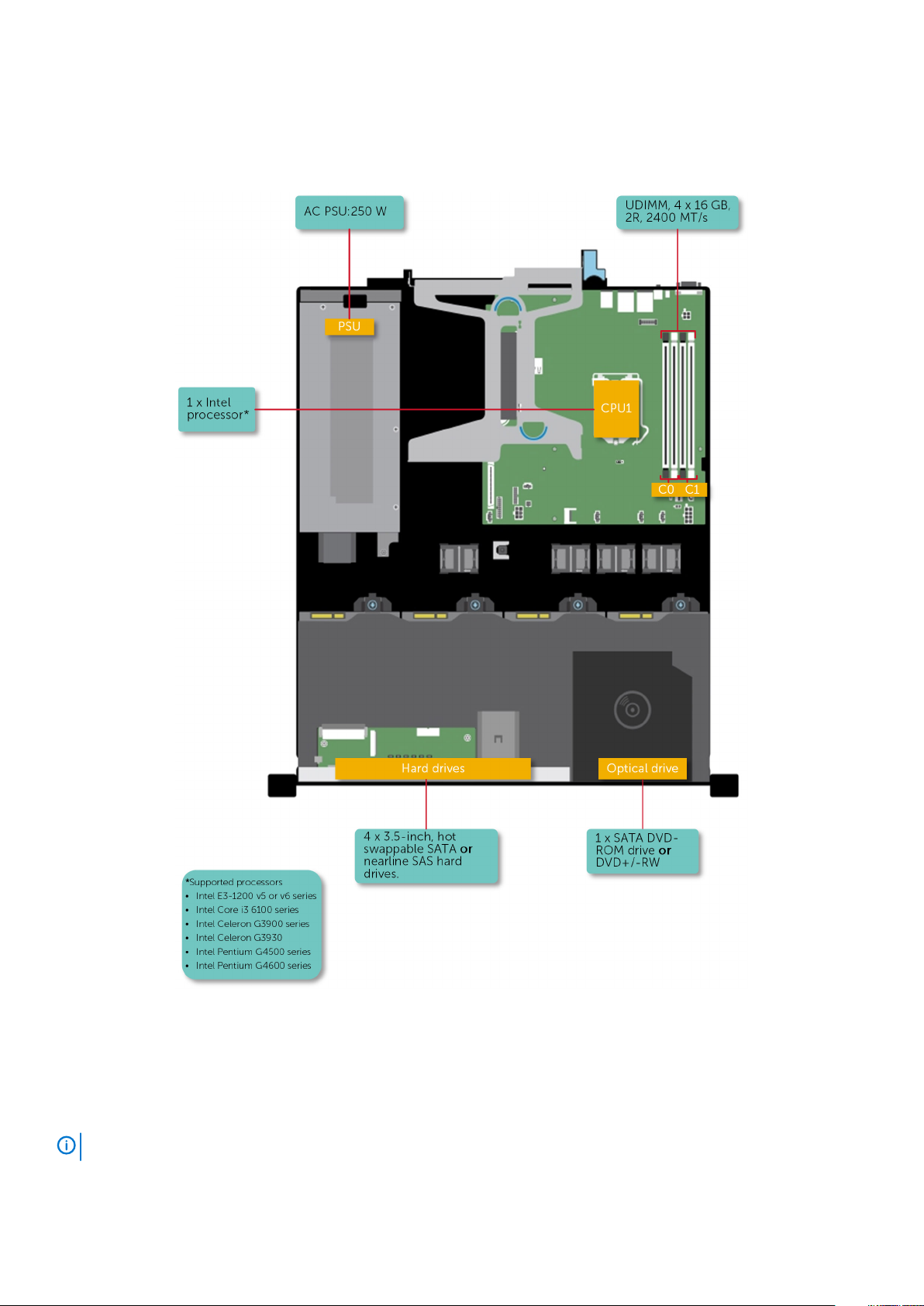
Supported configurations on PowerEdge R230 systems
Figure 1. System view with supported configurations
Supported configurations on PowerEdge R230 systems
NOTE:
Your system supports internal, hot swappable hard drives and cabled hard drives.
About the PowerEdge R230 systems 9
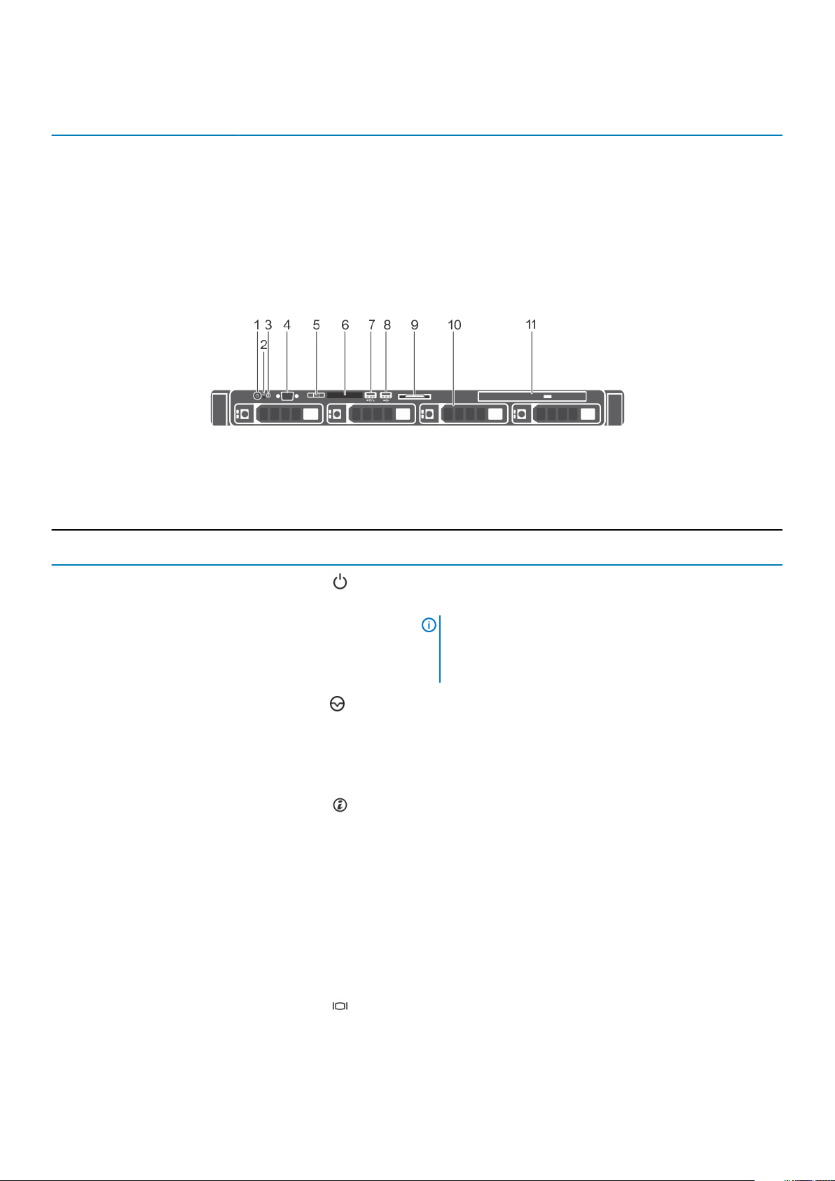
Table 1. Supported configurations on PowerEdge R230 systems
PowerEdge R230 Systems Configurations
Two hard drive systems Up to two 3.5-inch cabled hard drives with non-redundant cabled power supply unit (PSU)
Four hard drive systems Up to four 3.5- inch cabled hard drives with non-redundant cabled PSU
Up to four 2.5-inch hot swappable hard drives in 3.5-inch hard drive adapters, with non-redundant
cabled PSU
Up to four 3.5-inch hot swappable hard drives with non-redundant cabled PSU
Front panel features and indicators
Figure 2. Front panel features and indicators — four 3.5-inch or 2.5-inch hot swappable hard drive chassis
Table 2. Front panel features and indicators — four 3.5-inch or 2.5-inch hot swappable hard drive chassis
Item Indicator, button, or
connector
1 Power-on indicator, power
button
2 NMI button
3 System identification button Enables you to locate a particular system within a rack. The
Icon Description
Enables you to know the power status of the system. The poweron indicator glows when the system power is on. The power button
controls the power supply output to the system.
NOTE: On ACPI-compliant operating systems, turning
off the system using the power button causes the
system to perform a graceful shutdown before power to
the system is turned off.
Enables you to troubleshoot software and device driver errors
when running certain operating systems. This button can be
pressed by using the end of a paper clip.
Use this button only if directed to do so by qualified support
personnel or by the operating system's documentation.
identification buttons are on the front and back panels. When one
of these buttons is pressed, the LCD panel on the front and the
system status indicator on the back flash until one of the buttons is
pressed again.
Press the button to turn the system ID on and off.
If the system stops responding during POST, press and hold the
system ID button for more than five seconds to enter BIOS
progress mode.
To reset iDRAC (if not disabled in F2 iDRAC setup) press and hold
the button for more than 15 seconds.
4 Video connector Enables you to connect a display to the system.
5 LCD menu buttons Enable you to navigate the control panel LCD menu.
10 About the PowerEdge R230 systems
Item Indicator, button, or
connector
6 LCD panel Displays system ID, status information, and system error messages.
Icon Description
See LCD panel features.
NOTE: LCD panel is not available in a cabled hard drive
chassis.
7 USB management port/iDRAC
Direct port
8 USB connector Enables you to connect USB devices to the system. The port is
9 Information tag Contains system information such as service tag, NIC, MAC
10 Hard drives Enables you to install up to four 3.5-inch hot swappable hard drives
11 Optical drive (optional) Enables you to install an optional slim SATA DVD-ROM drive or
Functions as a regular USB port or provides access to the iDRAC
Direct features. For more information, see the iDRAC User’s Guide
at Dell.com/idracmanuals.
USB 2.0-compliant.
address for your reference. The information tag is a slide-out label
panel.
or up to four 2.5-inch hot swappable hard drives in 3.5-inch hot
swappable adapters.
DVD+/-RW drive.
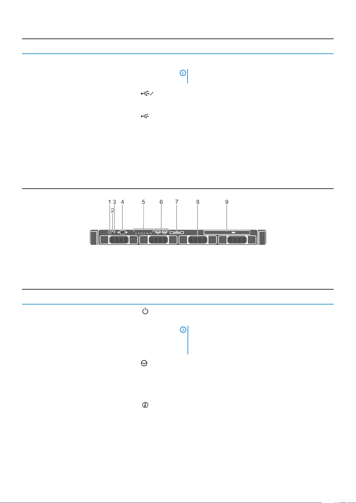
Figure 3. Front panel features and indicators — four 3.5-inch cabled hard drive chassis
Table 3. Front panel features and indicators — four 3.5-inch cabled hard drive chassis
Item Indicator, Button, or
Connector
1 Power-on indicator, power
button
2 NMI button Enables you to troubleshoot software and device driver errors
3 System identification button Enables you to locate a particular system within a rack. The
Icon Description
Enables you to know the power status of the system. The poweron indicator glows when the system power is on. The power button
controls the power supply output to the system.
NOTE: On ACPI-compliant operating systems, turning
off the system using the power button causes the
system to perform a graceful shutdown before power to
the system is turned off.
when running certain operating systems. This button can be
pressed by using the end of a paper clip.
Use this button only if directed to do so by qualified support
personnel or by the operating system's documentation.
identification buttons are on the front and back panels. When one
of these buttons is pressed, the LCD panel on the front and the
system status indicator on the back flash until one of the buttons is
pressed again.
Press the button to turn the system ID on or off. If the system
stops responding during POST, press and hold the system ID
button for more than five seconds to enter BIOS progress mode.
About the PowerEdge R230 systems 11
Item Indicator, Button, or
Connector
4 Video connector Enables you to connect a display to the system.
5 Diagnostic indicators The diagnostic indicator glows to display error status. For more
6 USB connectors Enable you to connect USB devices to the system. The port is USB
7 Information tag Contains system information such as service tag, NIC, MAC
8 Hard drives Enables you to install up to four 3.5-inch cabled hard drives.
9 Optical drive (optional) Enables you to install an optional slim SATA DVD-ROM drive or
Icon Description
To reset the iDRAC (if not disabled in F2 iDRAC setup) press and
hold the button for more than 15 seconds.
information, see Diagnostic indicators on the front panel.
2.0-compliant.
address for your reference. The information tag is a slide-out label
panel.
DVD+/-RW drive.
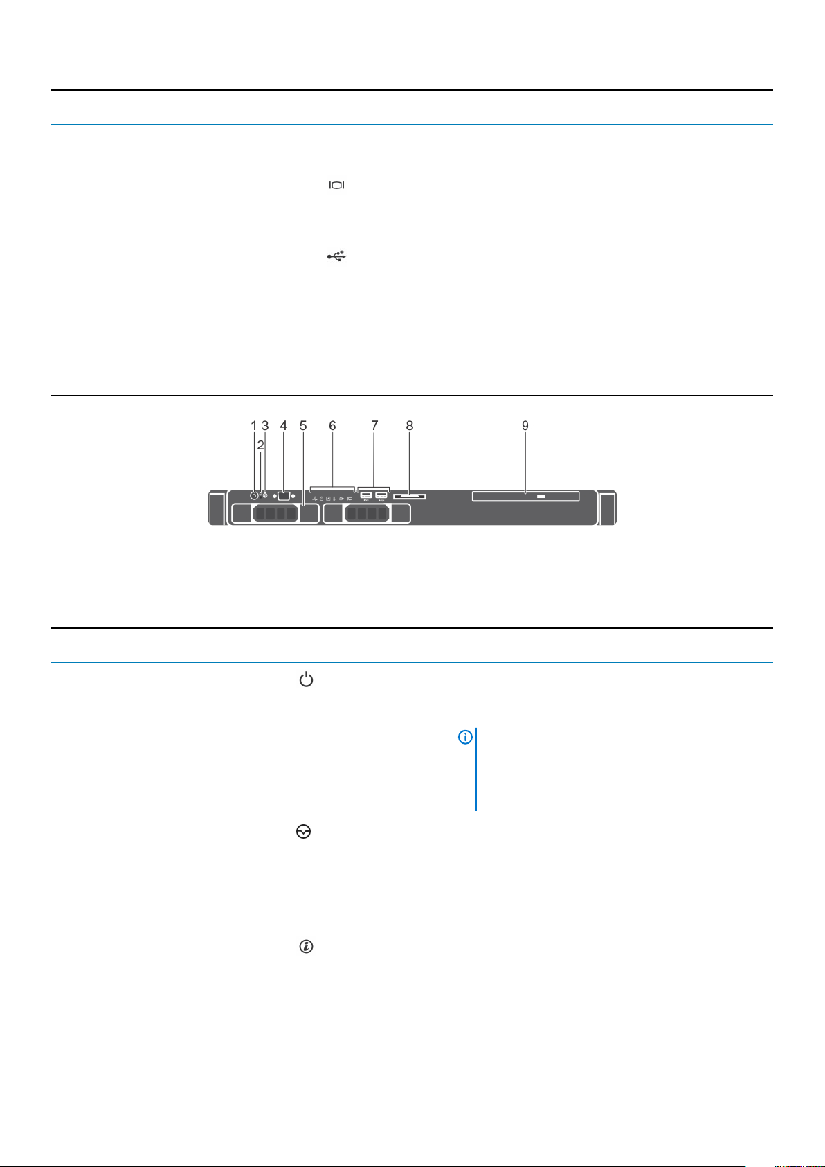
Figure 4. Front panel features and indicators — two 3.5-inch cabled hard drive chassis
Table 4. Front panel features and indicators — two 3.5-inch cabled hard drive chassis
Item Indicator, Button, or
Connector
1 Power-on indicator, power
button
2 NMI button
3 System identification button Enables you to locate a particular system within a rack. The
Icon Description
Enables you to know the power status of the system. The
power-on indicator glows when the system power is on.
The power button controls the power supply output to the
system.
NOTE: On ACPI-compliant operating systems,
turning off the system using the power button
causes the system to perform a graceful
shutdown before power to the system is turned
off.
Enables you to troubleshoot software and device driver
errors when running certain operating systems. This button
can be pressed by using the end of a paper clip.
Use this button only if directed to do so by qualified
support personnel or by the operating system's
documentation.
identification buttons are on the front and back panels.
When one of these buttons is pressed, the LCD panel on
the front and the system status indicator on the back flash
until one of the buttons is pressed again.
Press the button to turn the system ID on or off. If the
system stops responding during POST, press and hold the
12 About the PowerEdge R230 systems
Item Indicator, Button, or
Connector
4 Video connector Enables you to connect a display to the system.
5 Hard drives Enables you to install up to two 3.5-inch cabled hard drives.
6 Diagnostic indicators The diagnostic indicator glows to display error status. For
7 USB connectors Enable you to connect USB devices to the system. The
8 Information tag Contains system information such as service tag, NIC,
9 Optical drive (optional) Enables you to install an optional slim SATA DVD-ROM
Icon Description
system ID button for more than five seconds to enter BIOS
progress mode.
To reset the iDRAC (if not disabled in F2 iDRAC setup)
press and hold the button for more than 15 seconds.
more information, see Diagnostic indicators on the front
panel.
port is USB 2.0-compliant.
MAC address for your reference. The information tag is a
slide-out label panel.
drive or DVD+/-RW drive.
LCD panel features
The system's LCD panel provides system information and status and error messages to indicate if the system is operating correctly or if
the system needs attention. For more information about the error messages, see the Dell Event and Error Messages Reference Guide at
Dell.com/openmanagemanuals > OpenManage software.
• The LCD backlight turns blue during normal operating conditions and turns amber to indicate an error condition.
• The LCD backlight is turned off when the system is in standby mode and can be turned on by pressing either the Select, Left, or Right
button on the LCD panel.
• The LCD backlight remains OFF if LCD messaging is turned off through the iDRAC utility, the LCD panel, or other tools.
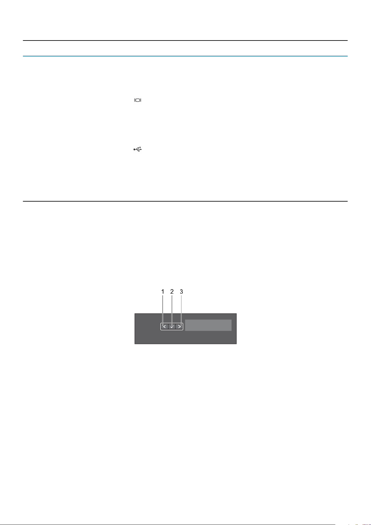
Figure 5. LCD panel Features
1. Left
2. Select
3. Right
Button
Left Moves the cursor back in one-step increments.
Select Selects the menu item highlighted by the cursor.
Right Moves the cursor forward in one-step increments.
Description
During message scrolling:
• Press once to increase scrolling speed
• Press again to stop
• Press again to return to the default scrolling speed
• Press again to repeat the cycle
About the PowerEdge R230 systems 13

Home screen
The Home screen displays user-configurable information about the system. This screen is displayed during normal system operation when
there are no status messages or errors. When the system is in standby mode, the LCD backlight turns off after five minutes of inactivity if
there are no error messages. Press one of the three navigation buttons (Select, Left, or Right) to view the Home screen.
To navigate to the Home screen from another menu, complete the following steps:
1. Press and hold the up arrow until the Home icon is displayed.
2. Select the Home icon.
3. On the Home screen, press the Select button to enter the main menu.
Setup menu
NOTE:
When you select an option in the Setup menu, you must confirm the option before proceeding to the next action.
Option Description
iDRAC Select DHCP or Static IP to configure the network mode. If Static IP is selected, the available fields are IP,
Subnet (Sub), and Gateway (Gtw). Select Setup DNS to enable DNS and to view domain addresses. Two
separate DNS entries are available.
Set error Select SEL to view LCD error messages in a format that matches the IPMI description in the SEL. This enables
you to match an LCD message with an SEL entry.
Select Simple to view LCD error messages in a simplified user-friendly description. For more information about
error messages, see the
OpenManage software.
Set home Select the default information to be displayed on the Home screen. See View menu section for the options and
option items that can be set as the default on the Home screen.
Dell Event and Error Messages Reference Guide at Dell.com/openmanagemanuals >
View menu
NOTE:
Option Description
iDRAC IP Displays the IPv4 or IPv6 addresses for iDRAC8. Addresses include DNS (Primary and Secondary), Gateway,
MAC Displays the MAC addresses for iDRAC, iSCSI, or Network devices.
Name Displays the name of the Host, Model, or User String for the system.
Number Displays the Asset tag or the Service tag for the system.
Power Displays the power output of the system in BTU/hr or Watts. The display format can be configured in the Set
Temperature Displays the temperature of the system in Celsius or Fahrenheit. The display format can be configured in the Set
When you select an option in the View menu, you must confirm the option before proceeding to the next action.
IP, and Subnet (IPv6 does not have Subnet).
home submenu of the Setup menu.
home submenu of the Setup menu.
14 About the PowerEdge R230 systems
Back panel features and indicators
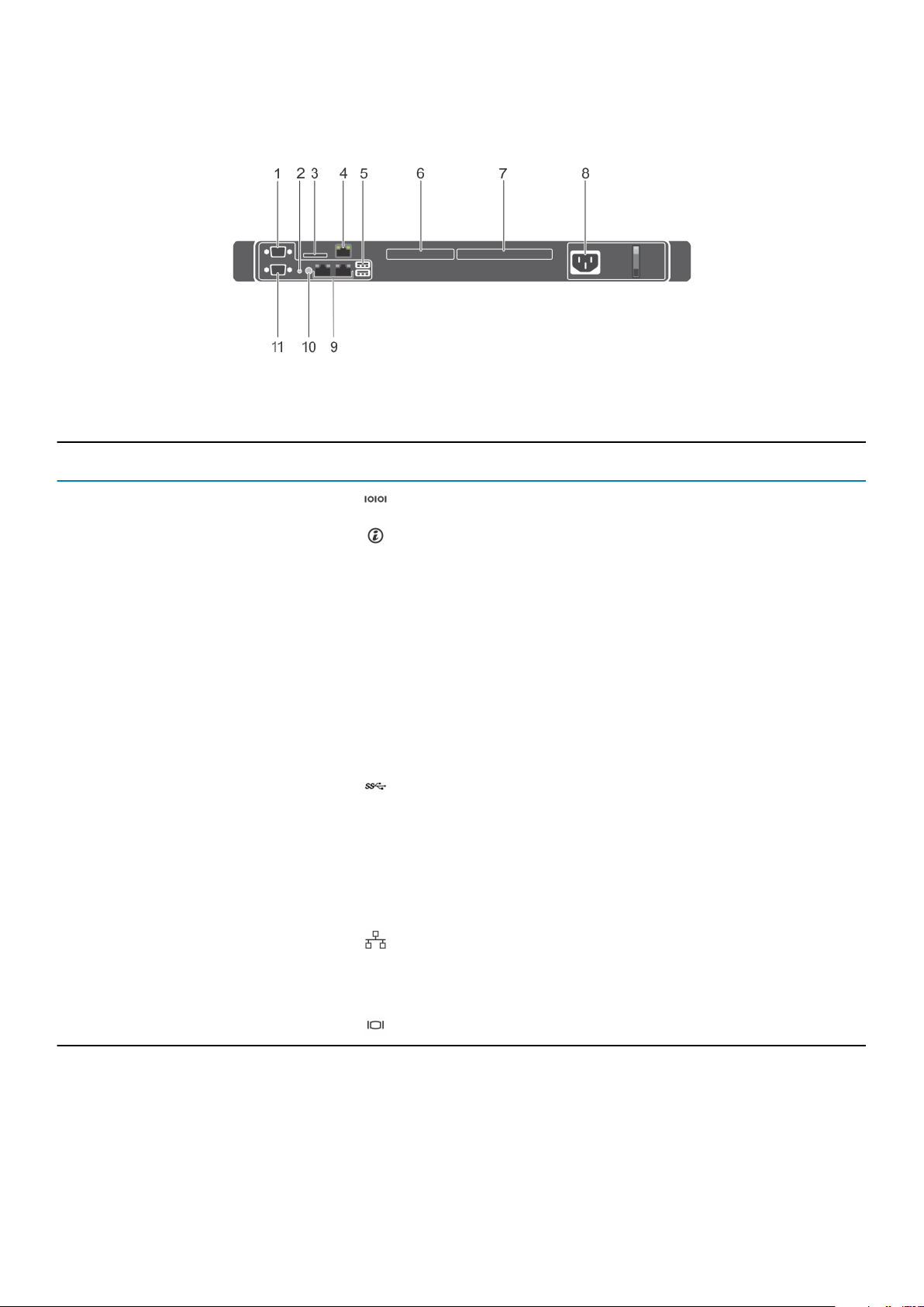
Figure 6. Back panel features and indicators
Table 5. Back panel features and indicators
Item Indicator, button, or
connector
1 Serial connector Enables you to connect a serial device to the system.
2 System identification button Enables you to locate a particular system within a rack. The
3 vFlash card slot (optional) Enables you to connect the vFlash card.
4 iDRAC port (optional) Enables you to install a dedicated management port card.
5 USB connectors (2) Enable you to connect USB devices to the system. The port is USB
6 PCIe expansion card slot (x8
slot, low profile)
7 PCIe expansion card slot (x16
slot, full height)
8 Power supply unit (PSU) Enables you to install one 250 W AC PSU.
9 Ethernet connectors Enable you to connect integrated 10/100/1000 Mbps NIC
10 System identification connector Connects the optional system status indicator assembly through
11 Video connector Enables you to connect a VGA display to the system.
Icon Description
identification buttons are on the front and back panels. When one
of these buttons is pressed, the LCD panel on the front and the
system status indicator on the back flash until one of the buttons is
pressed again.
Press the button to turn the system ID on or off. If the system
stops responding during POST, press and hold the system ID
button for more than five seconds to enter BIOS progress mode.
To reset the iDRAC (if not disabled in F2 iDRAC setup) press and
hold the button for more than 15 seconds.
3.0-compliant.
Enables you to connect a PCI Express expansion card.
connector.
the optional cable management arm.
About the PowerEdge R230 systems 15

Diagnostic indicators
The diagnostic indicators on the system indicate operation and error status.
Diagnostic indicators on the front panel
NOTE: No diagnostic indicators are lit when the system is turned off. To start the system, plug it into a working power
source and press the power button.
Table 6. Diagnostic indicators
Icon Description Condition Corrective action
Health indicator The indicator turns solid blue if the
system is in good health.
The indicator flashes amber:
• When the system is turned on.
• When the system is in standby.
• If any error condition exists. For
example, a failed fan, PSU, or a
hard drive.
Hard drive
indicator
Electrical indicator The indicator flashes amber if the
Temperature
indicator
Memory indicator The indicator flashes amber if a
The indicator flashes amber if there is
a hard drive error.
system experiences an electrical error
(for example, voltage out of range, or
a failed power supply unit (PSU) or
voltage regulator).
The indicator flashes amber if the
system experiences a thermal error
(for example, the ambient
temperature is out of range or fan
failure).
memory error occurs.
None required.
Check the System Event Log or system messages for
the specific issue. For more information about error
messages, see the Dell Event and Error Messages
Reference Guide at Dell.com/openmanagemanuals >
OpenManage software.
The POST process is interrupted without any video
output due to invalid memory configurations. See the
Getting help section.
Check the System Event Log to determine the hard drive
that has an error. Run the appropriate Online Diagnostics
test. Restart the system and run embedded diagnostics
(ePSA). If the hard drives are configured in a RAID array,
restart the system and enter the host adapter
configuration utility program.
Check the System Event Log or system messages for
the specific issue. If it is due to a problem with the PSU,
check the LED on the PSU. Reseat the PSU. If the
problem persists, see the Getting help section.
Ensure that none of the following conditions exist:
• A cooling fan has been removed or has failed.
• System cover, cooling shroud, EMI filler panel,
memory module blank, or back filler bracket is
removed.
• Ambient temperature is too high.
• External airflow is obstructed.
See the Getting help section.
Check the system event log or system messages for the
location of the failed memory. Reseat the memory
module. If the problem persists, see the Getting help
section.
16 About the PowerEdge R230 systems
Hard drive indicator codes
Each hard drive carrier has an activity indicator and a status indicator. The indicators provide information about the current status of the
hard drive. The activity LED indicates whether hard drive is currently in use or not. The status LED indicates the power condition of the
hard drive.
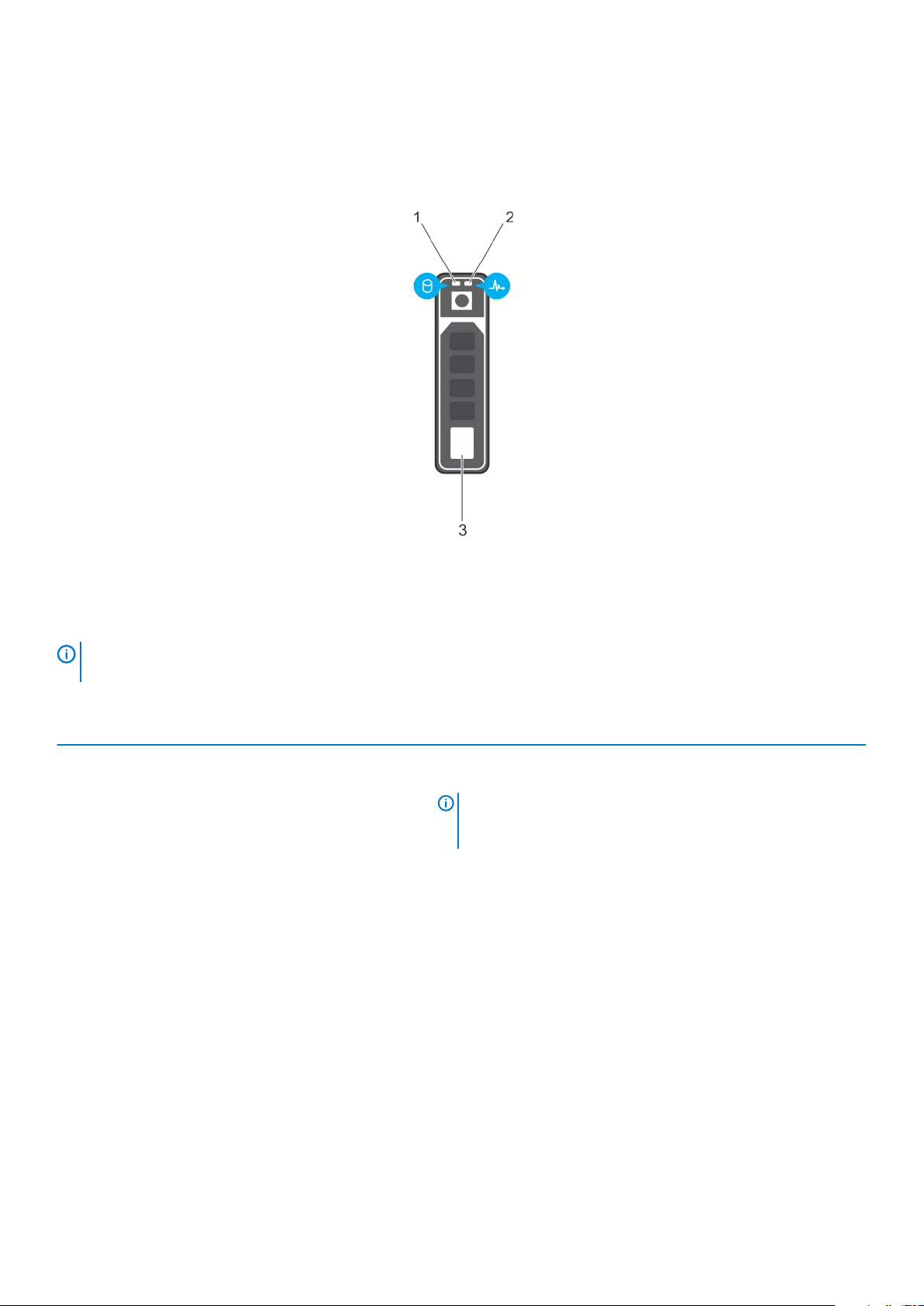
Figure 7. Hard drive indicators
1. Hard drive activity indicator
2. Hard drive status indicator
3. Hard drive
NOTE:
side) does not turn on.
Table 7. Hard drive indicator codes
Drive-status indicator pattern Condition
Flashes green twice per second Identifying drive or preparing for removal.
Off Drive ready for insertion or removal.
Flashes green, amber, and then turns off Predicted drive failure
Flashes amber four times per second Drive failed
Flashes green slowly Drive rebuilding
Steady green Drive online
Flashes green for three seconds, amber for three seconds, and
then turns off after six seconds
If the hard drive is in the Advanced Host Controller Interface (AHCI) mode, the status indicator (on the right
NOTE: The drive status indicator remains off until all hard
drives are initialized after the system is turned on. Drives are
not ready for insertion or removal during this time.
Rebuild stopped
About the PowerEdge R230 systems 17
NIC indicator codes
The NIC on the back panel has an indicator that provides information about the network activity and link status. The activity LED indicates
whether the NIC is currently connected or not. The link LED indicates the speed of the connected network.
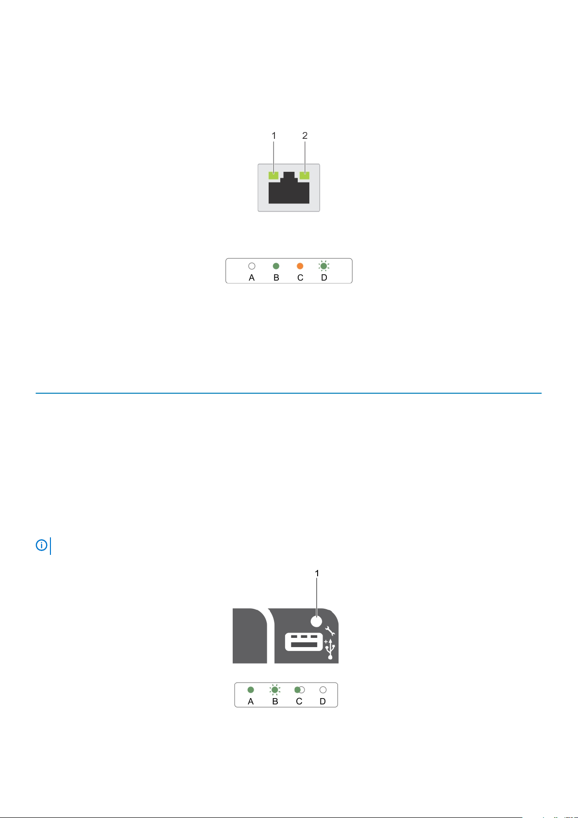
Figure 8. NIC Indicator Codes
1. link indicator
2. activity indicator
Table 8. NIC indicators
Convention Status Condition
A Link and activity indicators are off. The NIC is not connected to the network.
B Link indicator is green. The NIC is connected to a valid network at its maximum
port speed (1 Gbps or 10 Gbps).
C Link indicator is amber The NIC is connected to a valid network at less than its
maximum port speed.
D Activity indicator is flashing. green Network data is being sent or received.
iDRAC Direct LED indicator codes
The iDRAC Direct LED indicator lights up to indicate that the port is connected and is being used as a part of the iDRAC subsystem.
NOTE:
The iDRAC Direct LED indicator does not turn on when the USB port is used in the USB mode.
1. iDRAC Direct status indicator
18
About the PowerEdge R230 systems
The iDRAC Direct LED indicator table describes iDRAC Direct activity when configuring iDRAC Direct by using the management port (USB
XML Import).
Table 9. iDRAC Direct LED indicators
Convention iDRAC Direct LED
A Green Turns green for a minimum of two seconds to indicate the start and end of a
B Flashing green Indicates file transfer or any operation tasks.
C Green and turns off Indicates that the file transfer is complete.
D Not lit Indicates that the USB is ready to be removed or that a task is complete.
The following table describes iDRAC Direct activity when configuring iDRAC Direct by using your laptop and cable (Laptop Connect):
Table 10. iDRAC Direct LED indicator patterns
iDRAC Direct LED indicator pattern Condition
Solid green for two seconds Indicates that the laptop is connected.
Flashing green (on for two seconds and
off for two seconds)
Turns off Indicates that the laptop is unplugged.
indicator pattern
Indicates that the laptop connected is recognized.
Condition
file transfer.
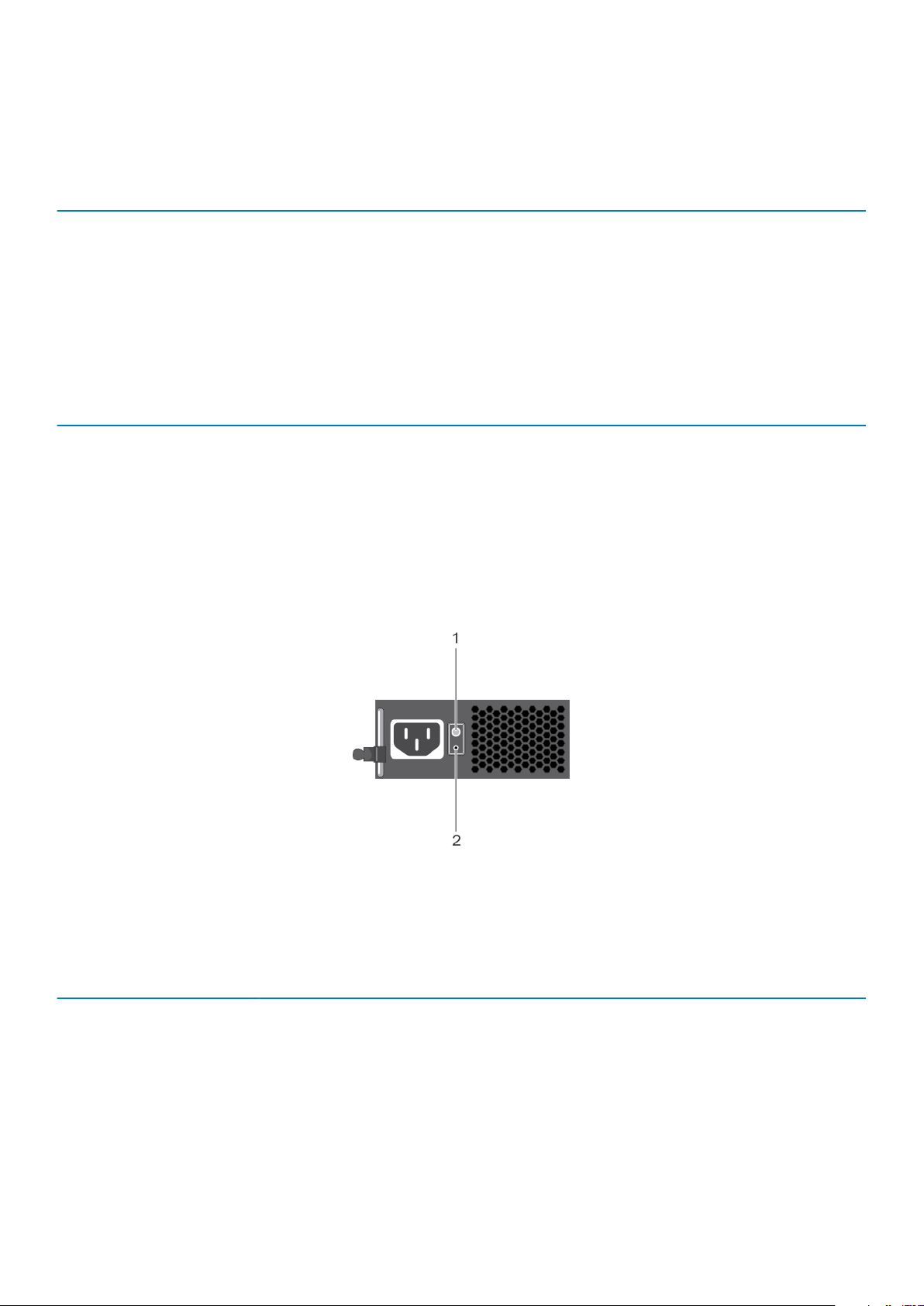
Non-redundant cabled power supply unit indicator codes
Press the self-diagnostic button to perform a quick health check on the non-redundant cabled power supply unit (PSU) of the system.
Figure 9. Non-redundant cabled AC PSU status indicator and self-diagnostic button
1. self-diagnostic button
2. AC PSU status indicator
Table 11. Non-redundant AC PSU status indicator
Power Indicator Pattern Condition
Not lit Power is not connected or PSU is faulty.
Green A valid power source is connected to the PSU and the PSU is operational.
Locating service tag of your system
Your system is identified by a unique Express Service Code and Service Tag number. The Express Service Code is and Service Tag are
found on the front of the system by pulling out the information tag. Alternatively, the information may be on a sticker on the chassis of the
system. This information is used by Dell to route support calls to the appropriate personnel.
About the PowerEdge R230 systems
19

Documentation resources
This section provides information about the documentation resources for your system.
To view the document that is listed in the documentation resources table:
• From the Dell EMC support site:
1. Click the documentation link that is provided in the Location column in the table.
2. Click the required product or product version.
NOTE:
3. On the Product Support page, click Manuals & documents.
• Using search engines:
• Type the name and version of the document in the search box.
Table 12. Additional documentation resources for your system
Task Document Location
Setting up your system
To locate the product name and model, see the front of your system.
For more information about installing and securing
the system into a rack, see the Rail Installation
Guide included with your rack solution.
For information about setting up your system, see
the Getting Started Guide document that is
shipped with your system.
www.dell.com/poweredgemanuals
2
Configuring your system For information about the iDRAC features,
configuring and logging in to iDRAC, and managing
your system remotely, see the Integrated Dell
Remote Access Controller User's Guide.
For information about understanding Remote
Access Controller Admin (RACADM)
subcommands and supported RACADM
interfaces, see the RACADM CLI Guide for iDRAC.
For information about Redfish and its protocol,
supported schema, and Redfish Eventing are
implemented in iDRAC, see the Redfish API Guide.
For information about iDRAC property database
group and object descriptions, see the Attribute
Registry Guide.
For information about earlier versions of the
iDRAC documents, see the iDRAC documentation.
To identify the version of iDRAC available on your
system, on the iDRAC web interface, click
About.
For information about installing the operating
system, see the operating system documentation.
For information about updating drivers and
firmware, see the Methods to download firmware
and drivers section in this document.
www.dell.com/poweredgemanuals
www.dell.com/idracmanuals
? >
www.dell.com/operatingsystemmanuals
www.dell.com/support/drivers
Managing your system For information about systems management
software offered by Dell, see the Dell
20 Documentation resources
www.dell.com/poweredgemanuals

Task Document Location
OpenManage Systems Management Overview
Guide.
Working with the Dell
PowerEdge RAID controllers
Understanding event and error
messages
For information about setting up, using, and
troubleshooting OpenManage, see the Dell
OpenManage Server Administrator User’s Guide.
For information about installing, using, and
troubleshooting Dell OpenManage Essentials, see
the Dell OpenManage Essentials User’s Guide.
For information about installing, using, and
troubleshooting Dell OpenManage Enterprise, see
the Dell OpenManage Enterprise User’s Guide.
For information about installing and using Dell
SupportAssist, see the Dell EMC SupportAssist
Enterprise User’s Guide.
For information about partner programs enterprise
systems management, see the OpenManage
Connections Enterprise Systems Management
documents.
For information about understanding the features
of the Dell PowerEdge RAID controllers (PERC),
Software RAID controllers, or BOSS card and
deploying the cards, see the Storage controller
documentation.
For information about the event and error
messages that are generated by the system
firmware and agents that monitor system
components, see the Error Code Lookup.
www.dell.com/openmanagemanuals >
OpenManage Server Administrator
www.dell.com/openmanagemanuals >
OpenManage Essentials
www.dell.com/openmanagemanuals >
OpenManage Enterprise
www.dell.com/serviceabilitytools
www.dell.com/openmanagemanuals
www.dell.com/storagecontrollermanuals
www.dell.com/qrl
Troubleshooting your system For information about identifying and
troubleshooting the PowerEdge server issues, see
the Server Troubleshooting Guide.
www.dell.com/poweredgemanuals
Documentation resources 21
Topics:
• Chassis dimensions
• Chassis weight
• Processor specifications
• Expansion bus specifications
• Memory specifications
• Power specifications
• Storage controller specifications
• Drive specifications
• Ports and connectors specifications
• Connectors specifications
• Video specifications
• Environmental specifications
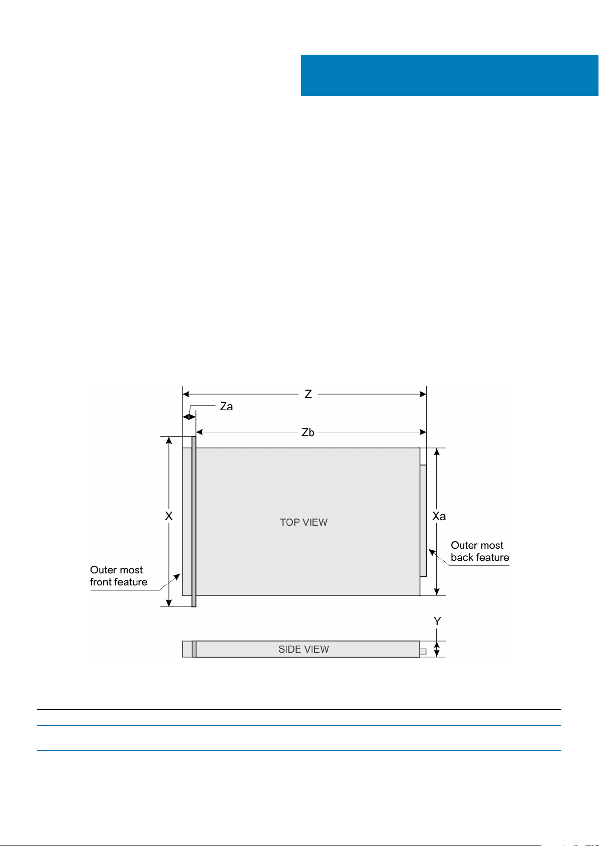
Chassis dimensions
This section describes the physical dimensions of the system.
3
Technical specifications
Figure 10. Chassis dimensions of the PowerEdge R230 system
Table 13. Dimensions of the Dell PowerEdge R230 system
X Xa Y Z (with bezel) Za Zb (without bezel)
482.38 mm (19
inches)
22 Technical specifications
434 mm (17.09
inches)
42.8 mm (1.68
inches)
532.1 mm ( 20.94
inches)
35.1 mm (1.38
inches)
497 mm (19.5
inches)

Chassis weight
This section describes the weight of the system.
Table 14. Chassis weight
System Maximum weight (with all hard drives/SSDs)
2.5-inch hot swappable hard drive
chassis
3.5-inch cabled hard drive chassis 8.77 kg (19.32 lb)
3.5-inch hot swappable hard drive
chassis
8.78 kg (19.35 lb)
9.51 kg (20.96 lb)
Processor specifications
Processor
Type The PowerEdge R230 supports any one of the processors listed here:
Specification
• Intel E3-1200 v5 or v6 series
• Intel Core i3 6100 series
• Intel Celeron G3900 series
• Intel Celeron G3930
• Intel Pentium G4500 series
• Intel Pentium G4600 series
Expansion bus specifications
PCI Express
Generation 3
expansion slots
using
expansion card
riser
PCIE_G3_X16 (Slot 1) one half-height, half-length x16 link for processor 1
PCIE_G3_X8 (Slot 1) one full-height, half-length x4 link for processor 1
Specification
(Slot 2) one full-height, half-length x16 link for processor 1
(Slot 2) one half-height, half-length x8 link for processor 1
Memory specifications
Memory
Architecture 1600 MT/s, 1866 MT/s, 2133 MT/s, or 2400 MT/s DDR4 Unbuffered DIMMs
Memory module
sockets
Memory module
capacities
(UDIMM)
Minimum RAM 4 GB
Specification
Support for advanced ECC or memory optimized operation
Four 288-pin sockets
4 GB (single-rank), 8 GB (single- and dual-rank), 16 GB (single- and dual-rank)
Technical specifications 23

Memory Specification
Maximum RAM 64 GB
Power specifications
Power supply
Specification
unit
Power rating per
power supply unit
(PSU)
Heat dissipation
Voltage
250 W (Bronze) AC (100–240 V, 50/60 Hz, 4.0 A-2.0 A)
NOTE: Heat dissipation is calculated using the PSU wattage rating.
1039 BTU/hr maximum (250 W PSU)
NOTE: This system is also designed to be connected to IT power systems with a phase-to-phase
voltage not exceeding 230 V.
100–240 V AC, autoranging, 50/60 Hz
Storage controller specifications
Storage
controller
Storage controller
type
Specification
PERC H730, PERC H330, PERC H830, PERC S130.
NOTE: Your system supports software RAID S130 and a PERC card.
For more information on software RAID, see the Dell PowerEdge RAID Controller (PERC)
documentation at Dell.com/storagecontrollermanuals.
NOTE: The upgrade from embedded controller or Software RAID controller to Hardware RAID
controller is not supported.
Drive specifications
Hard drives
The PowerEdge R230 system supports SAS, SATA, Nearline SAS hard drives and Solid State Drives (SSDs).
Drives
Four hard drive
systems
Two hard drive
systems
Optical drive
The PowerEdge R230 system supports one optional slim SATA DVD-ROM drive or DVD+/-RW drive.
Specification
Up to four 3.5-inch cabled hard drives, or
Up to four 2.5-inch hot swappable SATA, or Nearline SAS hard drives in 3.5-inch adapters, or
Up to four 3.5-inch hot swappable SATA, or Nearline SAS hard drives
Up to two 3.5-inch cabled hard drives
24
Technical specifications

Ports and connectors specifications
USB ports
The PowerEdge R230 system supports:
• USB 2.0-compliant ports on the front panel
• USB 3.0-compliant ports on the back panel
• USB 3.0-compliant internal port
The following table provides more information about the USB specifications:
Table 15. USB specifications
System Front panel Back panel Internal
PowerEdge R230 Two 4-pin, USB 2.0-compliant
ports
Two 9-pin, USB 3.0-compliant
port
NIC ports
The PowerEdge R230 system supports two 10/100/1000 Mbps Network Interface Controller (NIC) ports on the back panel.
iDRAC8
One 9-pin, USB 3.0-compliant
port
The PowerEdge R230 system supports one optional dedicated 1 GbE Ethernet on the iDRAC Enterprise port card.
Serial connector
The serial connector connects a serial device to the system. The PowerEdge R230 system supports one serial connector on the back
panel, which is a 9-pin connector, Data Terminal Equipment (DTE), 16550-compliant.
VGA ports
The Video Graphic Array (VGA) port enables you to connect the system to a VGA display. The PowerEdge R230 system supports two 15pin VGA ports one each on the front and back panels.
SD vFlash
The PowerEdge R230 system supports one optional SD vFlash memory card on the iDRAC Enterprise port card.
NOTE:
The card slot is available for use only if the iDRAC8 Enterprise license is installed on your system.
Connectors specifications
Back
connectors
Specification
NIC Two 10/100/1000 Mbps
Serial 9-pin, DTE, 16550-compatible
USB Two 9-pin, USB 3.0-compliant
Video 15-pin VGA
iDRAC8 One optional 1 GbE Ethernet
Technical specifications 25

Back
Specification
connectors
SD vFlash One optional SD vFlash memory card
NOTE: The card slot is available for use only if the iDRAC8 Enterprise license is installed on your
system.
Front
Specification
connectors
USB Two 4-pin, USB 2.0-compliant
Video 15-pin VGA
Internal
Specification
connectors
USB One 9-pin, USB 3.0-compliant
Video specifications
The PowerEdge R230 system supports Integrated Matrox G200 with iDRAC8 and 16 MB application memory.
Table 16. Supported video resolution options
Resolution Refresh Rate (Hz) Color Depth (bit)
640 x 480 60, 70 8, 16, 24
800 x 600 60, 75, 85 8, 16, 24
1024 x 768 60, 75, 85 8, 16, 24
1152 x 864 60, 75, 85 8, 16, 24
1280 x 1024 60, 75 8, 16, 24
Environmental specifications
NOTE:
environmental_datasheets.
Temperature Specifications
Storage –40°C to 65°C (–40°F to 149°F)
Continuous
operation (for
altitude less than
950 m or 3117 ft)
Maximum
temperature
gradient
(operating and
storage)
Relative
humidity
Storage 5% to 95% RH with 33°C (91°F) maximum dew point. Atmosphere must be non-condensing at all times.
Operating 10% to 80% Relative Humidity with 29°C (84.2°F) maximum dew point.
For additional information about environmental measurements for specific system configurations, see Dell.com/
10°C to 35°C (50°F to 95°F) with no direct sunlight on the equipment.
20°C/h (68°F/h)
Specifications
26 Technical specifications

Maximum
vibration
Specifications
Operating 0.26 G
Storage 1.88 G
Maximum
Specifications
at 5 Hz to 350 Hz (operation orientation).
rms
at 10 Hz to 500 Hz for 15 min (all six sides tested).
rms
shock
Operating Six consecutively executed shock pulses in the positive and negative x, y, and z axes of 40 G for up to 2.3 ms.
Storage Six consecutively executed shock pulses in the positive and negative x, y, and z axes (one pulse on each side of
the system) of 71 G for up to 2 ms.
Maximum
Specifications
altitude
Operating
Storage 12,000 m (39,370 ft).
Operating
30482000 m (10,0006560 ft).
Specifications
temperature
de-rating
Up to 35 °C (95
°F)
The following section defines the limits to help avoid IT equipment damage and/or failure from particulates and gaseous contamination. If
the levels of particulates or gaseous pollution are beyond the specified limits and cause equipment damage or failure, you may need to
rectify the environmental conditions. Remediation of environmental conditions is the responsibility of the customer.
Maximum temperature is reduced by 1°C/300 m (33.8°F/984.25 ft) above 950 m (3,117 ft)
Particulate
Specifications
contamination
Air filtration Data center air filtration as defined by ISO Class 8 per ISO 14644-1 with a 95% upper confidence limit.
NOTE: Applies to data center environments only. Air filtration requirements do not apply to IT
equipment designed to be used outside a data center, in environments such as an office or factory
floor.
NOTE: Air entering the data center must have MERV11 or MERV13 filtration.
Conductive dust Air must be free of conductive dust, zinc whiskers, or other conductive particles.
NOTE: Applies to data center and non-data center environments.
Corrosive dust
Gaseous
• Air must be free of corrosive dust.
• Residual dust present in the air must have a deliquescent point less than 60% relative humidity.
NOTE: Applies to data center and non-data center environments.
Specifications
contamination
Copper coupon
corrosion rate
Silver coupon
corrosion rate
<300 Å/month per Class G1 as defined by ANSI/ISA71.04-1985.
<200 Å/month as defined by AHSRAE TC9.9.
NOTE: Maximum corrosive contaminant levels measured at ≤50% relative humidity.
Technical specifications 27

Initial system setup and configuration
Setting up your system
Complete the following steps to set up your system:
Steps
1. Unpack the system.
2. Install the system into the rack. For more information about installing the system into the rack, see your system Rack Installation
Placemat at Dell.com/poweredgemanuals.
3. Connect the peripherals to the system.
4. Connect the system to its electrical outlet.
5. Turn the system on by pressing the power button or by using iDRAC.
6. Turn on the attached peripherals.
iDRAC configuration
The Integrated Dell Remote Access Controller (iDRAC) is designed to make system administrators more productive and improve the
overall availability of Dell EMC systems. iDRAC alerts administrators to system issues, helps them perform remote system management,
and reduces the need for physical access to the system.
4
Options to set up iDRAC IP address
You must configure the initial network settings based on your network infrastructure to enable the communication to and from iDRAC.
You can set up the IP address by using one of the following interfaces:
Interfaces
iDRAC Settings
utility
Dell Deployment
Toolkit
Dell Lifecycle
Controller
Chassis or Server
LCD panel
You must use the default iDRAC IP address 192.168.0.120 to configure the initial network settings, including setting up DHCP or a static IP
for iDRAC.
NOTE:
connector 1 on the system board.
NOTE: Ensure that you change the default user name and password after setting up the iDRAC IP address.
To access iDRAC, ensure that you install the iDRAC port card or connect the network cable to the Ethernet
Log in to iDRAC
Document/Section
See Dell Integrated Dell Remote Access Controller User's Guide at Dell.com/idracmanuals
See Dell Deployment Toolkit User’s Guide at Dell.com/openmanagemanuals
See Dell Lifecycle Controller User’s Guide at Dell.com/idracmanuals
See the LCD panel section
You can log in to iDRAC as:
• iDRAC user
• Microsoft Active Directory user
• Lightweight Directory Access Protocol (LDAP) user
28 Initial system setup and configuration

The default user name and password are root and calvin. You can also log in by using Single Sign-On or Smart Card.
NOTE: You must have iDRAC credentials to log in to iDRAC.
For more information about logging in to iDRAC and iDRAC licenses, see the latest Integrated Dell Remote Access Controller User's Guide
at Dell.com/idracmanuals.
Options to install the operating system
If the system is shipped without an operating system, install the supported operating system by using one of the following resources:
Table 17. Resources to install the operating system
Resources Location
Dell Systems Management Tools and Documentation media Dell.com/operatingsystemmanuals
Dell Lifecycle Controller Dell.com/idracmanuals
Dell OpenManage Deployment Toolkit Dell.com/openmanagemanuals
Dell certified VMware ESXi Dell.com/virtualizationsolutions
Supported operating systems on Dell PowerEdge systems Dell.com/ossupport
Installation and How-to videos for supported operating systems on
Dell PowerEdge systems
Supported Operating Systems for Dell PowerEdge Systems
Methods to download firmware and drivers
You can download the firmware and drivers by using any of the following methods:
Table 18. Firmware and drivers
Methods Location
From the Dell Support site Global Technical Support
Using Dell Remote Access Controller Lifecycle Controller (iDRAC
with LC)
Using Dell Repository Manager (DRM) Dell.com/openmanagemanuals > OpenManage Deployment Toolkit
Using Dell OpenManage Essentials (OME) Dell.com/openmanagemanuals > OpenManage Deployment Toolkit
Using Dell Server Update Utility (SUU) Dell.com/openmanagemanuals > OpenManage Deployment Toolkit
Using Dell OpenManage Deployment Toolkit (DTK) Dell.com/openmanagemanuals > OpenManage Deployment Toolkit
Downloading the drivers and firmware
Dell EMC recommends that you download and install the latest BIOS, drivers, and systems management firmware on your system.
Prerequisites
Ensure that you clear the web browser cache before downloading the drivers and firmware.
Steps
1. Go to Dell.com/support/drivers.
2. In the Drivers & Downloads section, type the Service Tag of your system in the Service Tag or Express Service Code box, and
then click Submit.
NOTE:
Service Tag, or in General support, navigate to your product.
3. Click Drivers & Downloads.
The drivers that are applicable to your selection are displayed.
4. Download the drivers to a USB drive, CD, or DVD.
If you do not have the Service Tag, select Detect My Product to allow the system to automatically detect your
Dell.com/idracmanuals
Initial system setup and configuration
29

Pre-operating system management
applications
You can manage basic settings and features of a system without booting to the operating system by using the system firmware.
Topics:
• Navigation keys
• System Setup
• About Boot Manager
• About Dell Lifecycle Controller
• Changing the boot order
• Choosing the system boot mode
• Creating a system or setup password
• Using your system password to secure your system
• Deleting or changing system and setup password
• Operating with a setup password enabled
• Embedded systems management
• iDRAC Settings utility
5
Navigation keys
The navigation keys can help you quickly access the pre-operating system management applications.
Table 19. Navigation keys
Key Description
<Page Up> Moves to the previous screen.
<Page Down> Moves to the next screen.
Up arrow Moves to the previous field.
Down arrow Moves to the next field.
<Enter> Enables you to type a value in the selected field (if applicable) or follow the link in the field.
Spacebar Expands or collapses a drop-down list, if applicable.
<Tab> Moves to the next focus area.
NOTE: This feature is applicable for the standard graphic browser only.
<Esc> Moves to the previous page until you view the main screen. Pressing <Esc> in the main screen exits System BIOS or
iDRAC Settings/ Device Settings/Service Tag Settings and proceeds with system boot.
<F1> Displays the System Setup help.
System Setup
By using the System Setup screen, you can configure the BIOS settings, iDRAC settings, and device settings of your system.
NOTE:
browser, press F1.
You can access system setup by using two methods:
• Standard graphical browser — The browser is enabled by default.
30 Pre-operating system management applications
Help text for the selected field is displayed in the graphical browser by default. To view the help text in the text
 Loading...