

Dell PowerEdge NM176, External OEMR R200, PowerEdge R200 Hardware Owner's Manual

Dell™ PowerEdge™ R200 Systems
Hardware Owner’s Manual
www.dell.com | support.dell.com
Notes, Notices, and Cautions
NOTE: A NOTE indicates important information that helps you make better use of
your computer.
NOTICE: A NOTICE indicates either potential damage to hardware or loss of data
and tells you how to avoid the problem.
CAUTION: A CAUTION indicates a potential for property damage, personal injury,
or death.
____________________
Information in this document is subject to change without notice.
© 2007 Dell Inc. All rights reserved.
Reproduction in any manner whatsoever without the written permission of Dell Inc. is strictly
forbidden.
Trademarks used in this text: Dell, the DELL logo, Inspiron, Dell Precision, Dimension, OptiPlex,
Latitude, PowerEdge, PowerVault, PowerApp, PowerConnect, and XPS are trademarks of Dell Inc.;
Intel, Pentium, and Celeron are registered trademarks of Intel Corporation; Microsoft, MS-DOS,
Windows, and W indows Server are either trademarks or registered trademarks of Microsoft Corporation
in the United States and/or other countries; Red Hat is a registered trademark of Red Hat, Inc.; SUSE
is a registered trademark of Novell, Inc. in the United States and other countries; UNIX is a registered
trademark of The Open Group in the United States and other countries; EMC is a registered trademark
of EMC Corporation.
Other trademarks and trade names may be used in this document to refer to either the entities claiming
the marks and names or their products. Dell Inc. disclaims any proprietary interest in trademarks and
trade names other than its own.
August 2007 P/N NM176 Rev. A00

Contents
1 About Your System . . . . . . . . . . . . . . . . . 11
Other Information You May Need . . . . . . . . . . . . 11
Accessing System Features During Startup
Front-Panel Features and Indicators
Back-Panel Features and Indicators
Connecting External Devices
NIC Indicator Codes
System Messages
Diagnostics Indicator Codes
System Beep Codes
Warning Messages
. . . . . . . . . . . . . . . . . . . 19
. . . . . . . . . . . . . . . . . . . . 19
. . . . . . . . . . . . . . 29
. . . . . . . . . . . . . . . . . . . 31
. . . . . . . . . . . . . . . . . . . 34
. . . . . . . . . . 13
. . . . . . . . . . 17
. . . . . . . . . . . 18
. . . . . . 12
Diagnostics Messages . . . . . . . . . . . . . . . . . 34
Alert Messages
. . . . . . . . . . . . . . . . . . . . . 34
2 Using the System Setup Program . . . . . . 35
Entering the System Setup Program . . . . . . . . . . 35
Responding to Error Messages
Using the System Setup Program
. . . . . . . . . . 35
. . . . . . . . . 36
Contents 3

System Setup Options . . . . . . . . . . . . . . . . . . 36
Main Screen
Memory Information Screen
CPU Information Screen
SATA Configuration Screen
Integrated Devices Screen
Console Redirection Screen
System Security Screen
Exit Screen
. . . . . . . . . . . . . . . . . . . . 36
. . . . . . . . . . . . 39
. . . . . . . . . . . . . . 39
. . . . . . . . . . . . 40
. . . . . . . . . . . . . 41
. . . . . . . . . . . . 42
. . . . . . . . . . . . . . 43
. . . . . . . . . . . . . . . . . . . . . 44
System and Setup Password Features
Using the System Password
Using the Setup Password
Disabling a Forgotten Password
. . . . . . . . . . . . 45
. . . . . . . . . . . . . 48
. . . . . . . . . . . . 49
Baseboard Management Controller
Configuration
. . . . . . . . . . . . . . . . . . . . . . 49
. . . . . . . . . 45
Entering the BMC Setup Module
BMC Setup Module Options
. . . . . . . . . . 50
. . . . . . . . . . . . 50
3 Installing System Components . . . . . . . . 51
Recommended Tools . . . . . . . . . . . . . . . . . . 51
Inside the System
Opening and Closing the System
Removing the Bezel
Installing the Bezel
Opening the System
Closing the System
. . . . . . . . . . . . . . . . . . . . 51
. . . . . . . . . . . . 53
. . . . . . . . . . . . . . . . 53
. . . . . . . . . . . . . . . . . 54
. . . . . . . . . . . . . . . . 54
. . . . . . . . . . . . . . . . . 55
4 Contents

Cooling Shroud . . . . . . . . . . . . . . . . . . . . . 56
Removing the Cooling Shroud
Installing the Cooling Shroud
System Battery
. . . . . . . . . . . . . . . . . . . . . . 58
Replacing the System Battery
Optical Drive
. . . . . . . . . . . . . . . . . . . . . . 60
Removing the Optical Drive
Installing the Optical Drive
Configuring the Boot Drive
Hard Drives
. . . . . . . . . . . . . . . . . . . . . . . 62
Removing a Hard Drive
Installing a Hard Drive
. . . . . . . . . . . . . . . 62
. . . . . . . . . . . . . . . 63
. . . . . . . . . . . . . . . 67
Installing a SAS Controller Card
. . . . . . . . . . . 56
. . . . . . . . . . . 57
. . . . . . . . . . . 58
. . . . . . . . . . . . 60
. . . . . . . . . . . . . 61
. . . . . . . . . . . . 68
Fan Assembly
Removing the Fan Assembly
Installing the Fan Assembly
Optional PCI Fan Assembly
Removing the PCI Fan Assembly
Installing the PCI Fan Assembly
. . . . . . . . . . . . . . . . . . . . . . 68
. . . . . . . . . . . . 69
. . . . . . . . . . . . 70
. . . . . . . . . . . . . . . 71
. . . . . . . . . . 71
. . . . . . . . . . 72
Power Supply . . . . . . . . . . . . . . . . . . . . . . 73
Removing the Power Supply
Installing the Power Supply
Expansion Cards
. . . . . . . . . . . . . . . . . . . . . 75
Installing an Expansion Card
Removing an Expansion Card
. . . . . . . . . . . . 73
. . . . . . . . . . . . 75
. . . . . . . . . . . . 75
. . . . . . . . . . . 78
Contents 5

Riser Card . . . . . . . . . . . . . . . . . . . . . . . . 79
Removing the Riser Card
Installing the Riser Card
System Memory
. . . . . . . . . . . . . . . . . . . . . 81
. . . . . . . . . . . . . . 79
. . . . . . . . . . . . . . 80
Memory Module Installation Guidelines
Installing Memory Modules
Removing Memory Modules
Processor
. . . . . . . . . . . . . . . . . . . . . . . . 85
Replacing the Processor
. . . . . . . . . . . . 82
. . . . . . . . . . . . 84
. . . . . . . . . . . . . . 85
Control Panel Assembly (Service-Only
Procedure)
. . . . . . . . . . . . . . . . . . . . . . . . 89
Removing the Control Panel Assembly
Installing the Control Panel Assembly
System Board (Service-Only Procedure)
Removing the System Board Assembly
. . . . . . 81
. . . . . . . 89
. . . . . . . 90
. . . . . . . . 91
. . . . . . 91
Installing the System Board Assembly
. . . . . . . 94
4 Troubleshooting Your System . . . . . . . . . 97
Safety First—For You and Your System . . . . . . . . . 97
Start-Up Routine
Checking the Equipment
Troubleshooting IRQ Assignment Conflicts
Troubleshooting External Connections
Troubleshooting the Video Subsystem
Troubleshooting the Keyboard
Troubleshooting the Mouse
Troubleshooting Basic I/O Functions
Troubleshooting a Serial I/O Device
. . . . . . . . . . . . . . . . . . . . . 97
. . . . . . . . . . . . . . . . . 98
. . . . 98
. . . . . . . 99
. . . . . . . 99
. . . . . . . . . . . 100
. . . . . . . . . . . . 101
. . . . . . . . 101
. . . . . . . . 102
6 Contents

Troubleshooting a USB Device . . . . . . . . . . 102
Troubleshooting a NIC
. . . . . . . . . . . . . . . 103
Responding to a Systems Management Software
Alert Message
Troubleshooting a Wet System
Troubleshooting a Damaged System
Troubleshooting the System Battery
Troubleshooting the Power Supply
Troubleshooting System Cooling Problems
Troubleshooting a Fan
Troubleshooting System Memory
Troubleshooting an Optical Drive
. . . . . . . . . . . . . . . . . . . . . . 104
. . . . . . . . . . . . . 104
. . . . . . . . . . 105
. . . . . . . . . . 106
. . . . . . . . . . . 106
. . . . . . . 107
. . . . . . . . . . . . . . . 108
. . . . . . . . . . . . 108
. . . . . . . . . . . . 110
Troubleshooting a Hard Drive
Troubleshooting Expansion Cards
Troubleshooting the Microprocessor
. . . . . . . . . . . . . . 111
. . . . . . . . . . . 113
. . . . . . . . . . 114
5 Running the System Diagnostics . . . . . 117
Using Dell PowerEdge Diagnostics . . . . . . . . . . 117
System Diagnostics Features
When to Use the System Diagnostics
Running the System Diagnostics
From the Utility Partition
From Removable Bootable Media
. . . . . . . . . . . . . . 117
. . . . . . . . . . 118
. . . . . . . . . . . . 118
. . . . . . . . . . . . . . 118
. . . . . . . . . 118
Contents 7

System Diagnostics Testing Options . . . . . . . . . . 119
Using the Custom Test Options
Selecting Devices for Testing
Selecting Diagnostics Options
Viewing Information and Results
. . . . . . . . . . . . . 119
. . . . . . . . . . . 120
. . . . . . . . . . . 120
. . . . . . . . . . 120
6 Jumpers and Connectors . . . . . . . . . . . 121
System Board Jumpers . . . . . . . . . . . . . . . . . 121
System Board Connectors
Riser Card Connectors
. . . . . . . . . . . . . . . . 122
. . . . . . . . . . . . . . . . . . 124
Disabling a Forgotten Password . . . . . . . . . . . . 125
7 Getting Help . . . . . . . . . . . . . . . . . . . . . . 127
Obtaining Assistance . . . . . . . . . . . . . . . . . . 127
Online Services
Automated Order-Status Service
Support Service
Dell Enterprise Training and Certification
Problems With Your Order
Product Information
Returning Items for Warranty Repair or Credit
Before You Call
Contacting Dell
. . . . . . . . . . . . . . . . . . . 128
. . . . . . . . . 129
. . . . . . . . . . . . . . . . . . 129
. . . . . . . 129
. . . . . . . . . . . . . . . . 129
. . . . . . . . . . . . . . . . . . . 129
. . . . . 130
. . . . . . . . . . . . . . . . . . . . . 131
. . . . . . . . . . . . . . . . . . . . . 133
8 Contents

Glossary . . . . . . . . . . . . . . . . . . . . . . . . . . . . 165
Index . . . . . . . . . . . . . . . . . . . . . . . . . . . . . . 177
Contents 9
10 Contents
About Your System
This section describes the physical, firmware, and software interface features
that provide and ensure the essential functioning of your system. The
physical connectors on your system’s front and back panels provide
convenient connectivity and system expansion capability. The system
firmware, applications, and operating systems monitor the system and
component status and alert you when a problem arises. System conditions
can be reported by any of the following:
• Front or back panel indicators
• System messages
• Diagnostic indicator codes
• Beep codes
• Warning messages
• Diagnostics messages
• Alert messages
This section describes each type of message, lists the possible causes, and
provides steps to resolve any problems indicated by a message. The system
indicators and features are illustrated in this section.
Other Information You May Need
CAUTION: The Product Information Guide provides important safety and
regulatory information. Warranty information may be included within this
document or as a separate document.
• The
• The
• CDs included with your system provide documentation and tools for
Rack Installation Guide
with your rack solution describe how to install your system into a rack.
Getting Started Guide
up your system, and technical specifications.
configuring and managing your system.
and
Rack Installation Instructions
provides an overview of system features, setting
included
About Your System 11
• Systems management software documentation describes the features,
requirements, installation, and basic operation of the software.
• Operating system documentation describes how to install (if necessary),
configure, and use the operating system software.
• Documentation for any components you purchased separately provides
information to configure and install these options.
• Updates are sometimes included with the system to describe changes to
the system, software, and/or documentation.
NOTE: Always check for updates on support.dell.com and read the updates
first because they often supersede information in other documents.
• Release notes or readme files may be included to provide last-minute
updates to the system or documentation or advanced technical reference
material intended for experienced users or technicians.
Accessing System Features During Startup
Table 1-1 describes keystrokes that may be entered during startup to access
system features. If your operating system begins to load before you enter the
keystroke, allow the system to finish booting, and then restart your system
and try again.
Table 1-1. Keystrokes for Accessing System Features
Keystroke Description
<F2> Enters the System Setup program. See "Using the System Setup
Program" on page 35.
<F10> Opens the utility partition, allowing you to run the system
diagnostics. See "Running the System Diagnostics" on page 118.
<Ctrl+E> Enters the Baseboard Management Controller (BMC) Management
Utility, which allows access to the system event log (SEL). See the
BMC User’s Guide for more information on setup and use of BMC.
<Ctrl+C> Enters the SAS Configuration Utility. See your SAS adapter User’s
Guide for more information.
<Ctrl+R> Enters the RAID configuration utility, which allows you to configure
an optional RAID card. For more information, see the documentation
for your RAID card.
12 About Your System
Table 1-1. Keystrokes for Accessing System Features (continued)
Keystroke Description
<Ctrl+S> Option is displayed only if you have PXE support enabled through the
System Setup Program (see "SATA Configuration Screen" on page 40
for options and descriptions for the information fields that appear on
the SATA Configuration screen). This keystroke allows you to
configure NIC settings for PXE boot. For more information, see the
documentation for your integrated NIC.
<Ctrl+D> If you have the optional Dell Remote Access Controller (DRAC), this
keystroke allows access to selected DRAC configuration settings. See
the DRAC User’s Guide for more information on setup and use of
DRAC.
Front-Panel Features and Indicators
Figure 1-1 shows the controls, indicators, connectors, and features on the
system front panel behind the optional bezel. (To remove the bezel, press the
latch at the left end of the bezel. See "Opening the System" on page 54.)
Table 1-2 provides component descriptions.
About Your System 13
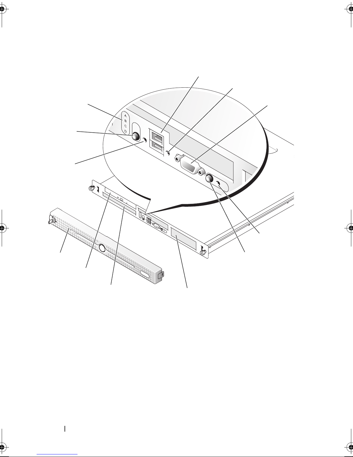
Figure 1-1. Front-Panel Features and Indicators
3
4
11
12
2
5
1
6
7
10
9
14 About Your System
8
Table 1-2. Front-Panel Components
Item Component Icon Description
1 Power-on indicator,
power button
The power button turns system power off
and on.
NOTICE: If you turn off the system
using the power button and the
system is running an ACPI-compliant
operating system, the system can
perform an orderly shutdown before
power is turned off. If the power
button is pressed for more than
4 seconds, the system power will turn
off regardless of the current
operating system state. If the system
is not running an ACPI-compliant
operating system, power is turned off
immediately after the power button is
pressed.
The power button is enabled in the
System Setup program. When disabled,
the button can only turn the system
power on. For more information, see
"Using the System Setup Program" on
page 35 and the operating system's
documentation.
The power-on indicator lights or blinks to
indicate the status of power to the system.
The power-on indicator lights when the
system is on. The indicator is off when the
system is off and power is disconnected
from the system. The indicator blinks
when the system is on but in standby
state, or when the system is off but is still
connected to the power source.
To exit from the standby state, briefly
press the power button.
About Your System 15
Table 1-2. Front-Panel Components (continued)
Item Component Icon Description
2 Diagnostic
indicators (4)
The diagnostic indicators aid in
diagnosing and troubleshooting the
system. For more information, see
"Diagnostics Indicator Codes" on page 29.
3 USB connectors (2) Connect USB 2.0-compliant devices to
the system.
4 Hard-drive activity
indicator
The green hard-drive activity indicator
flashes when the hard drives are in use.
5 Video connector Connects a monitor to the system.
6 System status
indicator
The blue system status indicator lights up
during normal system operation.
The amber system status indicator flashes
when the system needs attention due to a
system problem.
7 System
identification
button
You can use the system identification
buttons on the front and back panels to
locate a particular system within a rack.
When one of these buttons is pushed, the
blue system status indicators on the front
and back panels blink until one of the
buttons is pushed again.
8 Hard drive 1 Optional 3.5-inch SAS or SATA hard
9 Hard drive 0 A 3.5-inch SAS or SATA hard drive.
10 Optical drive Optional.
11 Bezel Optional
16 About Your System
You can also use the systems management
software to cause the indicators to flash to
identify a particular system.
drive.
Table 1-2. Front-Panel Components (continued)
Item Component Icon Description
12 NMI button The NMI button is used to troubleshoot
software and device driver errors when
using certain operating systems. This
button can be pressed using the end of a
paper clip. Use this button only if directed
to do so by qualified support personnel or
by the operating system's documentation.
Back-Panel Features and Indicators
Figure 1-2 shows the controls, indicators, and connectors located on the
system's back panel.
About Your System 17
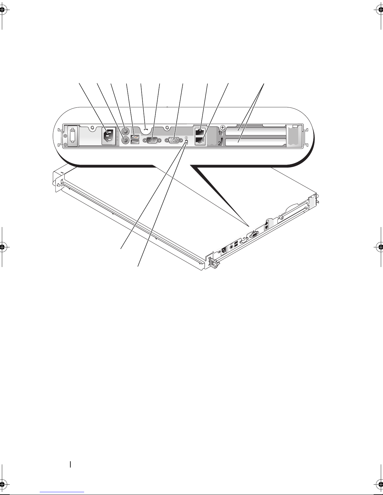
Figure 1-2. Back-Panel Features and Indicators
324 67 101
12
895
11
1 power supply
connector
4 USB connectors (2) 5 Kensington lock 6 serial connector
7 video connector 8 NIC1 connector 9 NIC2 connector
10 expansion slots (2) 11 system status
2 keyboard connector 3 mouse connector
12 system identification
indicator
button
Connecting External Devices
When connecting external devices to your system, follow these guidelines:
• Most devices must be connected to a specific connector and device drivers
must be installed before the device operates properly. (Device drivers are
normally included with your operating system software or with the device
itself.) See the documentation that accompanied the device for specific
installation and configuration instructions.
18 About Your System
• Always attach an external device while your system and the device are
turned off. Next, turn on any external devices before turning on the system
(unless the documentation for the device specifies otherwise).
See "Using the System Setup Program" on page 35 for information about
enabling, disabling, and configuring I/O ports and connectors.
NIC Indicator Codes
Each NIC on the back panel has an indicator that provides information on
network activity and link status. See Figure 1-3. Table 1-3 lists the NIC
indicator codes.
Figure 1-3. NIC Indicators
1
1 link indicator 2 activity indicator
Table 1-3. NIC Indicator Codes
Indicator Indicator Code
Link and activity indicators are off. The NIC is not connected to the network.
Link indicator is green. The NIC is connected to a valid link partner
Activity indicator is blinking yellow. Network data is being sent or received.
2
on the network.
System Messages
System messages appear on the screen to notify you of a possible problem
with the system. Table 1-4 lists the system messages that can occur and the
probable cause and corrective action for each message.
About Your System 19
NOTE: If you receive a system message that is not listed in Table 1-4, check the
documentation for the application that is running when the message appears or the
operating system's documentation for an explanation of the message and
recommended action.
CAUTION: Only trained service technicians are authorized to remove the system
cover and access any of the components inside the system. Before performing any
procedure, see your Product Information Guide for complete information about
safety precautions, working inside the computer and protecting against
electrostatic discharge.
Table 1-4. System Messages
Message Causes Corrective Actions
Attempting to
update Remote
Remote Configuration is in
progress.
Configuration.
Please wait....
BIOS Update Attempt
Failed!
Caution! NVRAM_CLR
jumper is installed
Remote BIOS update
attempt failed.
NVRAM_CLR jumper is
installed.
on system board.
Data error The diskette drive or hard
drive cannot read the data.
Wait until the process is
complete.
Retry the BIOS update. If
the problem persists, see
"Getting Help" on
page 127.
Check the System Setup
configuration settings. See
"Using the System Setup
Program
" on page 35.
Remove the NVRAM_CLR
jumper. See Figure 6-1 for
jumper locations.
For the operating system,
run the appropriate utility
to check the file structure
of the diskette drive or hard
drive.
20 About Your System
See your operating system
documentation for
information on running
these utilities.
Table 1-4. System Messages (continued)
Message Causes Corrective Actions
Decreasing
available memory
Diskette read
failure
Diskette subsystem
reset failed
One or more memory
modules might be
improperly seated or faulty.
Faulty or improperly
inserted diskette.
Faulty diskette drive or
optical drive controller.
Reinstall the memory
modules and, if necessary,
replace them. See "System
Memory" on page 81.
See "Troubleshooting
System Memory" on
page 108.
Replace the diskette.
Ensure that the diskette
drive and optical drive
cables are properly
connected. See
"Troubleshooting a USB
Device" on page 102 and
"Troubleshooting an
Optical Drive" on page 110.
If the problem persists, see
"Getting Help" on
page 127.
Drive not ready Diskette missing or
improperly inserted in
diskette drive.
Error: Incorrect
memory
configuration.
The installed memory
modules are not matched
pairs.
Ensure memory in
slots DIMM1_A and
DIMM1_B, DIMM2_A
and DIMM2_B match
identically in
size, speed and
rank.
Reinsert or replace the
diskette.
See "Memory Module
Installation Guidelines" on
page 81.
About Your System 21
Table 1-4. System Messages (continued)
Message Causes Corrective Actions
Error: Remote
Access Controller
Faulty or improperly
installed RAC.
initialization
failure.
Error 8602:
Auxiliary device
failure. Verify
that mouse and
Loose or improperly
connected mouse or
keyboard cable; faulty
mouse or keyboard.
keyboard are
securely attached
to correct
connectors.
Gate A20 failure Faulty keyboard controller
(faulty system board).
General failure The operating system is
unable to carry out the
command.
Ensure that the RAC is
properly installed. See
"Troubleshooting
Expansion Cards" on
page 113.
Replace the mouse. If the
problem persists, replace
the keyboard.
See "Getting Help" on
page 127.
This message is usually
followed by specific
information. Take the
appropriate action to
resolve the problem.
Keyboard controller
failure
Keyboard data line
failure
Keyboard failure
Keyboard stuck key
failure
Keyboard fuse has
failed.
22 About Your System
Faulty keyboard controller
(faulty system board).
Loose or improperly
connected keyboard cable;
faulty keyboard; faulty
keyboard controller.
See "Getting Help" on
page 127.
Ensure that the keyboard is
properly connected. If the
problem persists, replace
the keyboard. If the
problem persists, see
"Getting Help" on
page 127.
Keyboard fuse has failed. Replace the keyboard.
Faulty system board. If the problem persists, the
system board is faulty. See
"Getting Help" on
page 127.
Table 1-4. System Messages (continued)
Message Causes Corrective Actions
Manufacturing mode
detected
Memory address line
failure at
read
value
expecting
address
value
,
Memory double word
logic failure at
address
expecting
, read
value
value
Memory odd/even
logic failure at
start address
to
end address
Memory write/read
failure at
read
value
expecting
address
value
,
System is incorrectly
configured.
Faulty or improperly
installed memory modules,
or faulty system board.
Ensure that all memory
modules are properly
installed. See
"Troubleshooting System
Memory" on page 108. If
the problem persists, see
"Getting Help" on
page 127.
Memory tests
terminated by
keystroke
No boot device
available
The spacebar was pressed
during POST to terminate
the memory test.
The system cannot find the
diskette or hard drive.
Information only.
If the diskette drive is your
boot device, ensure that a
bootable disk is in the drive.
If the hard drive is your
boot device, ensure that the
hard drive is installed,
properly seated, and
partitioned as a boot
device.
Enter the System Setup
program and verify the boot
sequence information. See
your Hardware Owner’s
Manual for details.
About Your System 23
Table 1-4. System Messages (continued)
Message Causes Corrective Actions
No boot sector on
hard-disk drive
No timer tick
interrupt
The system configuration
information in the System
Setup program might be
incorrect.
A chip on the system board
might be malfunctioning.
Enter the System Setup
program and verify the
system configuration
information for the hard
drive. See your Hardware
Owner’s Manual for details.
If the message continues to
appear after verifying the
information in the System
Setup program, the
operating system might
have been corrupted.
Reinstall the operating
system. See your operating
system documentation for
reinstallation information.
Run the system diagnostics.
See "Running the System
Diagnostics" on page 117.
Not a boot diskette The operating system is
trying to boot from a
diskette that does not have
a bootable operating system
installed on it.
Option ROM Checksum
Error
PCI device BIOS (Option
ROM) checksum failure is
detected during shadowing.
Insert a diskette that has a
bootable operating system.
Ensure that all appropriate
cables are securely
connected to the expansion
cards. If the problem
persists, see
"Troubleshooting
Expansion Cards" on
page 113.
24 About Your System
Table 1-4. System Messages (continued)
Message Causes Corrective Actions
PCIe Degraded Link
Width Error:
Embedded
nn
Bus#
/Dev#nn/Func
n
Expected Link Width
n
is
Actual Link Width
is
n
PCIe Degraded Link
Width Error: Slot
n
Expected Link Width
n
is
Actual Link Width
is
n
PCIe Training
Error: Embedded
nn
Bus#
/Dev#nn/Func
n
Faulty or improperly
installed PCIe card.
Faulty or improperly
installed PCIe card in the
specified slot number.
Faulty or improperly
installed PCIe card.
Reseat the PCIe cards. See
"Expansion Cards" on
page 75. If the problem
persists, see "Getting Help"
on page 127.
Reseat the PCIe card in the
specified slot number. See
"Expansion Cards" on
page 75. If the problem
persists, see "Getting Help"
on page 127.
Reseat the PCIe cards. See
"Expansion Cards" on
page 75. If the problem
persists, see "Getting Help"
on page 127.
PCIe Training
Error: Slot
n
Faulty or improperly
installed PCIe card in the
specified slot number.
Reseat the PCIe card in the
specified slot number. See
"Expansion Cards" on
page 75. If the problem
persists, see "Getting Help"
on page 127.
About Your System 25
Table 1-4. System Messages (continued)
Message Causes Corrective Actions
Plug & Play
Configuration Error
Read fault
Requested sector
not found
Error encountered in
initializing PCI device;
faulty system board.
The operating system
cannot read from the
diskette or hard drive, the
system could not find a
particular sector on the
disk, or the requested sector
is defective.
Install the NVRAM_CLR
jumper and reboot the
system. See Figure 6-1 for
jumper location. Check for
a BIOS update. If the
problem persists, see
"Troubleshooting
Expansion Cards" on
page 113. If the problem
persists, see "Getting Help"
on page 127.
Replace the diskette.
Ensure that the diskette
and hard-drive cables are
properly connected. See
"Troubleshooting a USB
Device" on page 102 or
"Troubleshooting a Hard
Drive" on page 111 for the
appropriate drive(s)
installed in your system.
Remote
Configuration
update attempt
failed
SATA port 0/1/2
hard disk drive
configuration error
SATA port 0/1/2
hard disk drive
failure
SATA port 0/1/2
hard disk drive
auto-sensing error
26 About Your System
System could not
implement Remote
Configuration request.
Faulty drive. Parameters
failure.
Faulty drive. INT13 call
failure from the drive.
Retry Remote
Configuration.
Ensure that the hard drive
cables are properly
connected. See
"Troubleshooting a Hard
Drive" on page 111.
Ensure that the hard drive
cables are properly
connected. See
"Troubleshooting a Hard
Drive" on page 111.
Table 1-4. System Messages (continued)
Message Causes Corrective Actions
SATA Port 0/1/2
hard disk not found
SATA Port 0/1/2 set as Auto,
no disk installed.
Run the System Setup
program to correct the
settings. See "Using the
System Setup Program" on
page 35.
Sector not found
Seek error
Faulty diskette or hard
drive.
See "Troubleshooting a
USB Device" on page 102
or "Troubleshooting a Hard
Seek operation
failed
Drive" on page 111 for the
appropriate drive installed
in your system.
Shutdown failure Shutdown test failure. Ensure that all memory
modules are properly
installed. See
"Troubleshooting System
Memory" on page 108. If
the problem persists, see
"Getting Help" on
page 127.
The amount of
system memory has
changed.
Time-of-day clock
stopped
Faulty memory module.
See "Troubleshooting
System Memory" on
page 108. If the problem
Information only, if you
have changed the memory
persists, see "Getting Help"
on page 127.
configuration.
Faulty memory module. See "Troubleshooting
System Memory" on
page 108. If the problem
persists, see "Getting Help"
on page 127.
Faulty battery; faulty
system board.
See "Troubleshooting the
System Battery" on
page 106. If the problem
persists, see "Getting Help"
on page 127.
About Your System 27
Table 1-4. System Messages (continued)
Message Causes Corrective Actions
Time-of-day not set
- please run SETUP
program
Timer chip counter
2 failed
Unexpected
interrupt in
protected mode
Incorrect Time or Date
settings; faulty system
battery.
Check the Time and Date
settings. See "Using the
System Setup Program" on
page 35. If the problem
persists, see
"Troubleshooting the
System Battery" on
page 106.
Faulty system board. See "Getting Help" on
page 127.
Faulty or improperly
installed memory modules
or faulty system board.
Ensure that all memory
modules are properly
installed. See "Memory
Module Installation
Guidelines" on page 81. If
the problem persists, see
"Troubleshooting System
Memory" on page 108. If
the problem persists, see
"Getting Help" on
page 127.
Utility partition
not available
Warning! No micro
code update loaded
for processor 0
28 About Your System
Utility partition is not
available on the hard disk
Create a utility partition on
the boot hard drive. See the
CDs that came with your
system.
Micro code update failed. Update the BIOS firmware.
See "Getting Help" on
page 127.
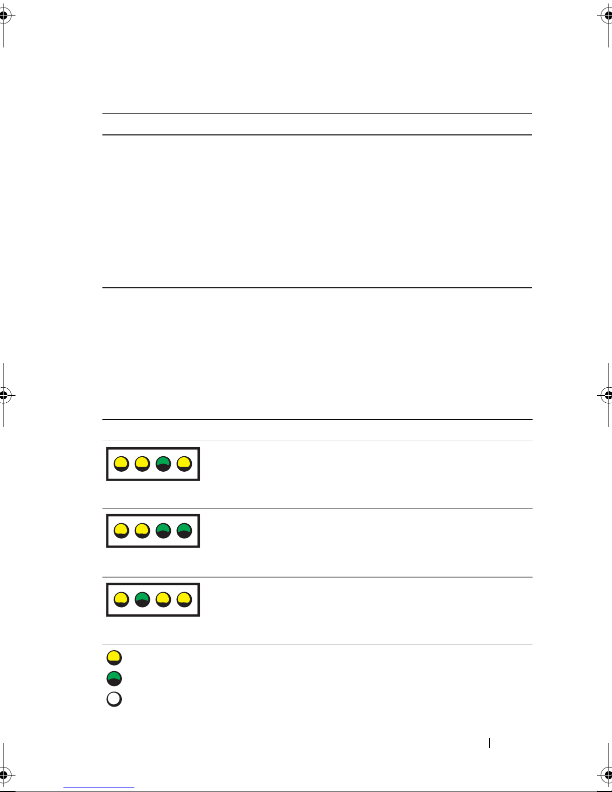
Table 1-4. System Messages (continued)
Message Causes Corrective Actions
Write fault
Write fault on
selected drive
Faulty diskette, diskette
drive, hard drive.
Replace the diskette.
Ensure that the diskette
drive and hard-drive cables
are properly connected. See
"Troubleshooting a USB
Device" on page 102 or
"Troubleshooting a Hard
Drive" on page 111 for the
appropriate drive(s)
installed in your system.
Diagnostics Indicator Codes
The four diagnostics indicators on the system front panel display error codes
during system startup. Table 1-5 lists the causes and possible corrective
actions associated with these codes.
Table 1-5. Diagnostic Indicator Codes
Code Causes Corrective Action
A B C D
A B C D
A B C D
= yellow
= green
= off
Possible processor
failure.
Memory failure. See "Troubleshooting System
Possible expansion
card failure.
See "Troubleshooting the
Microprocessor" on page 114.
Memory" on page 108.
See "Troubleshooting Expansion
Cards" on page 113.
About Your System 29
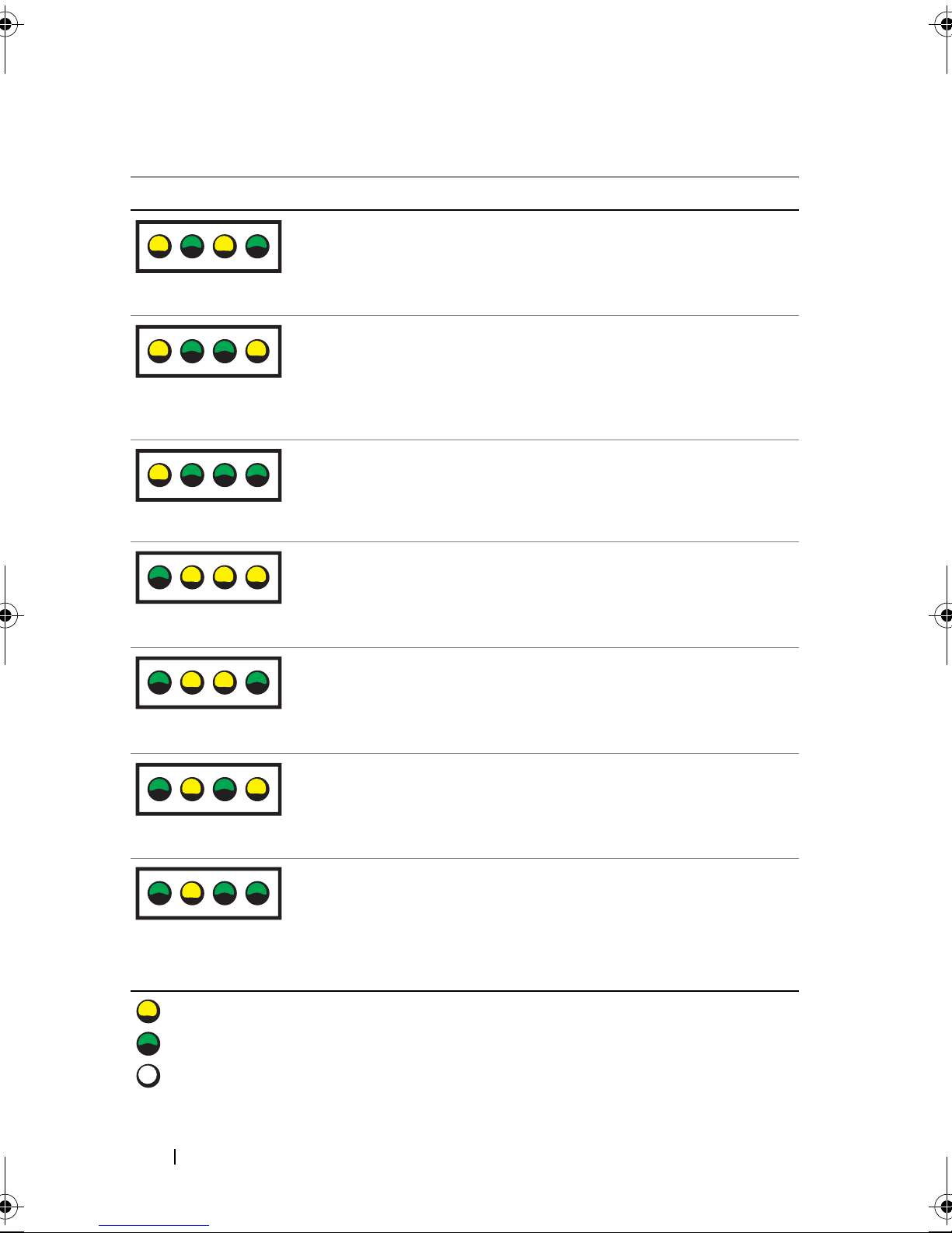
Table 1-5. Diagnostic Indicator Codes (continued)
Code Causes Corrective Action
A B C D
A B C D
A B C D
A B C D
Possible video card
failure.
Diskette drive or hard
drive failure.
Possible USB failure. See "Troubleshooting a USB Device"
No memory modules
detected.
System board failure. See "Getting Help" on page 127.
See "Troubleshooting Expansion
Cards" on page 113.
Ensure that the diskette drive and
hard-drive are properly connected.
See "Installing a Hard Drive" on
page 67 for information on the
drives installed in your system.
on page 102.
See "Troubleshooting System
Memory" on page 108.
A B C D
Memory
configuration error.
A B C D
Possible system board
resource and/or
system board
A B C D
= yellow
= green
= off
30 About Your System
hardware failure.
See "Troubleshooting System
Memory" on page 108.
See "Troubleshooting IRQ
Assignment Conflicts" on page 98.
If the problem persists, see "Getting
Help" on page 127.
 Loading...