

Page 1

Dell PowerEdge Configuration Guide for the
M I/O Aggregator
9.5(0.1)
Page 2

Notes, Cautions, and Warnings
NOTE: A NOTE indicates important information that helps you make better use of your computer.
CAUTION: A CAUTION indicates either potential damage to hardware or loss of data and tells you
how to avoid the problem.
WARNING: A WARNING indicates a potential for property damage, personal injury, or death.
Copyright © 2014 Dell Inc. All rights reserved. This product is protected by U.S. and international copyright and
intellectual property laws. Dell™ and the Dell logo are trademarks of Dell Inc. in the United States and/or other
jurisdictions. All other marks and names mentioned herein may be trademarks of their respective companies.
2014 - 07
Rev. A00
Page 3

Contents
1 About this Guide..................................................................................................13
Audience.............................................................................................................................................. 13
Conventions.........................................................................................................................................13
Related Documents.............................................................................................................................14
2 Before You Start.................................................................................................. 15
IOA Operational Modes.......................................................................................................................15
Standalone mode...........................................................................................................................15
Stacking mode............................................................................................................................... 15
VLT mode.......................................................................................................................................15
Programmable MUX mode............................................................................................................15
Default Settings................................................................................................................................... 16
Other Auto-Configured Settings........................................................................................................ 16
Data Center Bridging Support.............................................................................................................17
FCoE Connectivity and FIP Snooping.................................................................................................17
iSCSI Operation....................................................................................................................................17
Link Aggregation..................................................................................................................................18
Link Tracking........................................................................................................................................18
Configuring VLANs.............................................................................................................................. 18
Uplink LAG..................................................................................................................................... 18
Server-Facing LAGs....................................................................................................................... 19
Where to Go From Here......................................................................................................................19
3 Configuration Fundamentals........................................................................... 20
Accessing the Command Line........................................................................................................... 20
CLI Modes........................................................................................................................................... 20
Navigating CLI Modes....................................................................................................................21
The do Command...............................................................................................................................22
Undoing Commands...........................................................................................................................23
Obtaining Help.................................................................................................................................... 23
Entering and Editing Commands....................................................................................................... 24
Command History...............................................................................................................................25
Filtering show Command Outputs.....................................................................................................25
Multiple Users in Configuration Mode............................................................................................... 26
4 Data Center Bridging (DCB)..............................................................................27
Ethernet Enhancements in Data Center Bridging..............................................................................27
Priority-Based Flow Control...............................................................................................................28
Page 4

Configuring Priority-Based Flow Control.................................................................................... 29
Enhanced Transmission Selection......................................................................................................31
Configuring Enhanced Transmission Selection........................................................................... 33
Configuring DCB Maps and its Attributes.......................................................................................... 33
DCB Map: Configuration Procedure............................................................................................ 33
Important Points to Remember....................................................................................................34
Applying a DCB Map on a Port..................................................................................................... 35
Configuring PFC without a DCB Map...........................................................................................35
Configuring Lossless Queues....................................................................................................... 36
Data Center Bridging Exchange Protocol (DCBx)..............................................................................37
Data Center Bridging in a Traffic Flow............................................................................................... 38
Enabling Data Center Bridging........................................................................................................... 38
Data Center Bridging: Auto-DCB-Enable Mode................................................................................39
QoS dot1p Traffic Classification and Queue Assignment..................................................................41
How Priority-Based Flow Control is Implemented........................................................................... 42
How Enhanced Transmission Selection is Implemented..................................................................42
ETS Operation with DCBx.............................................................................................................43
Bandwidth Allocation for DCBX CIN............................................................................................44
DCBX Operation..................................................................................................................................44
DCBx Operation............................................................................................................................44
DCBx Port Roles............................................................................................................................45
DCB Configuration Exchange...................................................................................................... 46
Configuration Source Election..................................................................................................... 46
Propagation of DCB Information..................................................................................................47
Auto-Detection of the DCBx Version...........................................................................................47
DCBX Example.............................................................................................................................. 48
DCBX Prerequisites and Restrictions............................................................................................49
DCBX Error Messages................................................................................................................... 49
Debugging DCBX on an Interface................................................................................................49
Verifying the DCB Configuration........................................................................................................50
Hierarchical Scheduling in ETS Output Policies................................................................................ 59
5 Dynamic Host Configuration Protocol (DHCP)............................................ 61
Assigning an IP Address using DHCP..................................................................................................61
Debugging DHCP Client Operation................................................................................................... 63
DHCP Client........................................................................................................................................ 65
How DHCP Client is Implemented.....................................................................................................65
DHCP Client on a Management Interface......................................................................................... 66
DHCP Client on a VLAN......................................................................................................................66
DHCP Packet Format and Options.....................................................................................................67
Option 82............................................................................................................................................ 68
Releasing and Renewing DHCP-based IP Addresses........................................................................69
Page 5

Viewing DHCP Statistics and Lease Information............................................................................... 69
6 FIP Snooping........................................................................................................71
Fibre Channel over Ethernet............................................................................................................... 71
Ensuring Robustness in a Converged Ethernet Network...................................................................71
FIP Snooping on Ethernet Bridges......................................................................................................72
FIP Snooping in a Switch Stack...........................................................................................................75
How FIP Snooping is Implemented....................................................................................................75
FIP Snooping on VLANs.................................................................................................................75
FC-MAP Value................................................................................................................................75
Bridge-to-FCF Links...................................................................................................................... 76
Impact on other Software Features..............................................................................................76
FIP Snooping Prerequisites........................................................................................................... 76
FIP Snooping Restrictions............................................................................................................. 76
Displaying FIP Snooping Information................................................................................................. 77
FIP Snooping Example........................................................................................................................ 83
Debugging FIP Snooping ...................................................................................................................84
7 Internet Group Management Protocol (IGMP)............................................. 85
IGMP Overview....................................................................................................................................85
IGMP Version 2....................................................................................................................................85
Joining a Multicast Group.................................................................................................................. 86
Leaving a Multicast Group..................................................................................................................86
IGMP Version 3....................................................................................................................................86
Joining and Filtering Groups and Sources.........................................................................................87
Leaving and Staying in Groups...........................................................................................................88
IGMP Snooping................................................................................................................................... 89
How IGMP Snooping is Implemented on an Aggregator..................................................................89
Disabling Multicast Flooding.............................................................................................................. 90
Displaying IGMP Information............................................................................................................. 90
8 Interfaces............................................................................................................. 92
Basic Interface Configuration.............................................................................................................92
Advanced Interface Configuration..................................................................................................... 92
Interface Auto-Configuration.............................................................................................................92
Interface Types....................................................................................................................................93
Viewing Interface Information............................................................................................................93
Disabling and Re-enabling a Physical Interface.................................................................................95
Layer 2 Mode.......................................................................................................................................95
Management Interfaces......................................................................................................................96
Accessing an Aggregator.............................................................................................................. 96
Configuring a Management Interface..........................................................................................96
Page 6

Configuring a Static Route for a Management Interface.............................................................97
VLAN Membership.............................................................................................................................. 98
Default VLAN ................................................................................................................................ 98
Port-Based VLANs.........................................................................................................................98
VLANs and Port Tagging............................................................................................................... 99
Configuring VLAN Membership....................................................................................................99
Displaying VLAN Membership.................................................................................................... 100
Adding an Interface to a Tagged VLAN.......................................................................................101
Adding an Interface to an Untagged VLAN................................................................................ 101
Port Channel Interfaces....................................................................................................................102
Port Channel Definitions and Standards.................................................................................... 102
Port Channel Benefits................................................................................................................. 102
Port Channel Implementation....................................................................................................102
1GbE and 10GbE Interfaces in Port Channels............................................................................103
Uplink Port Channel: VLAN Membership................................................................................... 103
Server-Facing Port Channel: VLAN Membership.......................................................................103
Displaying Port Channel Information.........................................................................................104
Interface Range................................................................................................................................. 105
Bulk Configuration Examples......................................................................................................105
Monitor and Maintain Interfaces.......................................................................................................107
Maintenance Using TDR............................................................................................................. 108
Flow Control Using Ethernet Pause Frames.................................................................................... 108
MTU Size............................................................................................................................................109
Auto-Negotiation on Ethernet Interfaces........................................................................................ 110
Setting Auto-Negotiation Options..............................................................................................112
Viewing Interface Information.......................................................................................................... 113
Clearing Interface Counters........................................................................................................114
Enabling the Management Address TLV on All Interfaces of an Aggregator.................................. 115
Enhanced Validation of Interface Ranges.........................................................................................115
9 iSCSI Optimization........................................................................................... 116
iSCSI Optimization Overview............................................................................................................ 116
Monitoring iSCSI Traffic Flows.......................................................................................................... 117
Information Monitored in iSCSI Traffic Flows.................................................................................. 118
Detection and Auto configuration for Dell EqualLogic Arrays........................................................ 118
iSCSI Optimization: Operation..........................................................................................................118
Displaying iSCSI Optimization Information...................................................................................... 119
10 Isolated Networks for Aggregators.............................................................121
Configuring and Verifying Isolated Network Settings......................................................................121
11 Link Aggregation.............................................................................................122
Page 7

Supported Modes..............................................................................................................................122
How the LACP is Implemented on an Aggregator...........................................................................122
Uplink LAG................................................................................................................................... 123
Server-Facing LAGs..................................................................................................................... 123
LACP Modes.................................................................................................................................123
Auto-Configured LACP Timeout................................................................................................ 123
LACP Example................................................................................................................................... 124
Link Aggregation Control Protocol (LACP)...................................................................................... 125
Configuration Tasks for Port Channel Interfaces.......................................................................125
Creating a Port Channel..............................................................................................................125
Adding a Physical Interface to a Port Channel...........................................................................125
Reassigning an Interface to a New Port Channel.......................................................................127
Configuring the Minimum Oper Up Links in a Port Channel.................................................... 128
......................................................................................................................................................129
Deleting or Disabling a Port Channel......................................................................................... 129
Configuring the Minimum Number of Links to be Up for Uplink LAGs to be Active..................... 130
Optimizing Traffic Disruption Over LAG Interfaces On IOA Switches in VLT Mode.......................131
Preserving LAG and Port Channel Settings in Nonvolatile Storage.................................................131
Enabling the Verification of Member Links Utilization in a LAG Bundle..........................................131
Monitoring the Member Links of a LAG Bundle...............................................................................132
Verifying LACP Operation and LAG Configuration.......................................................................... 133
12 Layer 2...............................................................................................................137
Managing the MAC Address Table....................................................................................................137
Clearing the MAC Address Entries.............................................................................................. 137
Displaying the MAC Address Table.............................................................................................138
Network Interface Controller (NIC) Teaming.................................................................................. 138
MAC Address Station Move.........................................................................................................139
MAC Move Optimization.............................................................................................................140
13 Link Layer Discovery Protocol (LLDP).........................................................141
Overview............................................................................................................................................ 141
Protocol Data Units..................................................................................................................... 141
Optional TLVs.................................................................................................................................... 143
Management TLVs.......................................................................................................................143
LLDP Operation.................................................................................................................................143
Viewing the LLDP Configuration...................................................................................................... 144
Viewing Information Advertised by Adjacent LLDP Agents.............................................................144
Clearing LLDP Counters....................................................................................................................145
Debugging LLDP............................................................................................................................... 146
Relevant Management Objects.........................................................................................................147
Page 8

14 Port Monitoring.............................................................................................. 153
Configuring Port Monitoring.............................................................................................................153
Important Points to Remember........................................................................................................154
Port Monitoring................................................................................................................................. 155
15 Security for M I/O Aggregator......................................................................156
Understanding Banner Settings........................................................................................................ 156
Accessing the I/O Aggregator Using the CMC Console Only.........................................................156
AAA Authentication............................................................................................................................157
Configuration Task List for AAA Authentication.........................................................................157
RADIUS...............................................................................................................................................159
RADIUS Authentication............................................................................................................... 160
Configuration Task List for RADIUS............................................................................................160
TACACS+...........................................................................................................................................163
Configuration Task List for TACACS+........................................................................................ 163
TACACS+ Remote Authentication..............................................................................................167
Enabling SCP and SSH...................................................................................................................... 168
Using SCP with SSH to Copy a Software Image........................................................................ 169
Secure Shell Authentication........................................................................................................170
Troubleshooting SSH...................................................................................................................173
Telnet................................................................................................................................................. 173
VTY Line and Access-Class Configuration....................................................................................... 173
VTY Line Local Authentication and Authorization..................................................................... 174
VTY Line Remote Authentication and Authorization................................................................. 174
VTY MAC-SA Filter Support......................................................................................................... 175
16 Simple Network Management Protocol (SNMP)...................................... 176
Implementation Information............................................................................................................ 176
Configuring the Simple Network Management Protocol................................................................176
Important Points to Remember..................................................................................................176
Setting up SNMP.......................................................................................................................... 177
Creating a Community................................................................................................................ 177
Reading Managed Object Values...................................................................................................... 177
Displaying the Ports in a VLAN using SNMP.....................................................................................178
Fetching Dynamic MAC Entries using SNMP...................................................................................180
Deriving Interface Indices..................................................................................................................181
Monitor Port-Channels.....................................................................................................................182
Entity MIBS.........................................................................................................................................183
Example of Sample Entity MIBS outputs.................................................................................... 183
Standard VLAN MIB........................................................................................................................... 185
Enhancements.............................................................................................................................185
Page 9

Fetching the Switchport Configuration and the Logical Interface Configuration .................. 186
SNMP Traps for Link Status...............................................................................................................187
17 Stacking............................................................................................................188
Stacking Aggregators........................................................................................................................188
Stack Management Roles............................................................................................................189
Stack Master Election..................................................................................................................190
Failover Roles.............................................................................................................................. 190
MAC Addressing...........................................................................................................................191
Stacking LAG................................................................................................................................191
Stacking VLANs............................................................................................................................ 191
Stacking Port Numbers..................................................................................................................... 192
Configuring a Switch Stack...............................................................................................................194
Stacking Prerequisites................................................................................................................. 194
Cabling Stacked Switches...........................................................................................................194
Accessing the CLI........................................................................................................................ 195
Configuring and Bringing Up a Stack......................................................................................... 195
Adding a Stack Unit..................................................................................................................... 196
Resetting a Unit on a Stack.........................................................................................................196
Removing an Aggregator from a Stack and Restoring Quad Mode..........................................197
Configuring the Uplink Speed of Interfaces as 40 Gigabit Ethernet...............................................197
Verifying a Stack Configuration........................................................................................................199
Using Show Commands............................................................................................................. 199
Troubleshooting a Switch Stack.......................................................................................................201
Failure Scenarios.........................................................................................................................203
Upgrading a Switch Stack.................................................................................................................205
Upgrading a Single Stack Unit..........................................................................................................206
18 Broadcast Storm Control..............................................................................208
Disabling Broadcast Storm Control................................................................................................. 208
Displaying Broadcast-Storm Control Status................................................................................... 208
Configuring Storm Control.............................................................................................................. 208
19 System Time and Date...................................................................................209
Setting the Time for the Software Clock......................................................................................... 209
Setting the Timezone....................................................................................................................... 209
Setting Daylight Savings Time.......................................................................................................... 210
Setting Daylight Saving Time Once............................................................................................210
Setting Recurring Daylight Saving Time......................................................................................211
20 Uplink Failure Detection (UFD)....................................................................213
Feature Description...........................................................................................................................213
Page 10

How Uplink Failure Detection Works............................................................................................... 214
UFD and NIC Teaming...................................................................................................................... 216
Important Points to Remember........................................................................................................216
Configuring Uplink Failure Detection (PMUX mode)....................................................................... 217
Clearing a UFD-Disabled Interface (in PMUX mode).......................................................................218
Displaying Uplink Failure Detection.................................................................................................220
Sample Configuration: Uplink Failure Detection.............................................................................222
Uplink Failure Detection (SMUX mode)............................................................................................223
21 PMUX Mode of the IO Aggregator.............................................................. 224
Introduction...................................................................................................................................... 224
I/O Aggregator (IOA) Programmable MUX (PMUX) Mode.............................................................. 224
Configuring and Changing to PMUX Mode.....................................................................................224
Configuring the Commands without a Separate User Account.....................................................225
Multiple Uplink LAGs.........................................................................................................................225
Multiple Uplink LAGs with 10G Member Ports................................................................................ 226
..................................................................................................................................................... 226
Multiple Uplink LAGs with 40G Member Ports................................................................................ 227
..................................................................................................................................................... 227
Uplink Failure Detection (UFD).........................................................................................................229
..................................................................................................................................................... 229
Virtual Link Trunking (VLT) in PMUX Mode......................................................................................230
.....................................................................................................................................................230
Stacking in PMUX Mode....................................................................................................................232
..................................................................................................................................................... 232
Configuring an NPIV Proxy Gateway............................................................................................... 233
Enabling Fibre Channel Capability on the Switch............................................................................233
Creating a DCB Map......................................................................................................................... 234
Important Points to Remember....................................................................................................... 234
Applying a DCB Map on Server-Facing Ethernet Ports...................................................................234
Creating an FCoE VLAN....................................................................................................................235
Creating an FCoE Map .....................................................................................................................235
Applying a DCB Map on Server-Facing Ethernet Ports...................................................................236
Applying an FCoE Map on Fabric-Facing FC Ports......................................................................... 236
Sample Configuration.......................................................................................................................237
..................................................................................................................................................... 237
Displaying NPIV Proxy Gateway Information...................................................................................237
Link Layer Discovery Protocol (LLDP)..............................................................................................238
Configure LLDP...........................................................................................................................238
CONFIGURATION versus INTERFACE Configurations..............................................................239
Enabling LLDP............................................................................................................................. 239
Advertising TLVs..........................................................................................................................240
Page 11

Viewing the LLDP Configuration................................................................................................ 241
Viewing Information Advertised by Adjacent LLDP Agents.......................................................242
Configuring LLDPDU Intervals....................................................................................................243
Configuring a Time to Live......................................................................................................... 243
Debugging LLDP.........................................................................................................................244
Virtual Link Trunking (VLT)................................................................................................................245
Overview..................................................................................................................................... 246
VLT Terminology.........................................................................................................................247
Configure Virtual Link Trunking..................................................................................................247
Verifying a VLT Configuration.....................................................................................................252
Additional VLT Sample Configurations.......................................................................................255
Troubleshooting VLT...................................................................................................................257
22 FC Flex IO Modules........................................................................................ 259
FC Flex IO Modules...........................................................................................................................259
Understanding and Working of the FC Flex IO Modules.................................................................259
FC Flex IO Modules Overview.................................................................................................... 259
FC Flex IO Module Capabilities and Operations........................................................................ 261
Guidelines for Working with FC Flex IO Modules...................................................................... 261
Processing of Data Traffic.......................................................................................................... 263
Installing and Configuring the Switch........................................................................................264
Interconnectivity of FC Flex IO Modules with Cisco MDS Switches.........................................267
Fibre Channel over Ethernet for FC Flex IO Modules..................................................................... 268
NPIV Proxy Gateway for FC Flex IO Modules..................................................................................269
NPIV Proxy Gateway Configuration on FC Flex IO Modules ................................................... 269
NPIV Proxy Gateway Operations and Capabilities.................................................................... 269
Configuring an NPIV Proxy Gateway..........................................................................................273
Displaying NPIV Proxy Gateway Information............................................................................ 280
23 Upgrade Procedures......................................................................................286
Get Help with Upgrades................................................................................................................... 286
24 Debugging and Diagnostics.........................................................................287
Debugging Aggregator Operation................................................................................................... 287
All interfaces on the Aggregator are operationally down......................................................... 287
Broadcast, unknown multicast, and DLF packets switched at a very low rate........................ 288
Flooded packets on all VLANs are received on a server........................................................... 288
Software show Commands..............................................................................................................289
Offline Diagnostics............................................................................................................................291
Important Points to Remember..................................................................................................291
Running Offline Diagnostics....................................................................................................... 291
Trace Logs.........................................................................................................................................292
Page 12

Auto Save on Crash or Rollover................................................................................................. 292
Using the Show Hardware Commands........................................................................................... 293
Environmental Monitoring............................................................................................................... 294
Recognize an Over-Temperature Condition.............................................................................295
Troubleshoot an Over-Temperature Condition........................................................................296
Recognize an Under-Voltage Condition................................................................................... 297
Troubleshoot an Under-Voltage Condition...............................................................................297
Buffer Tuning.................................................................................................................................... 298
Deciding to Tune Buffers............................................................................................................299
Sample Buffer Profile Configuration.......................................................................................... 302
Troubleshooting Packet Loss...........................................................................................................303
Displaying Drop Counters.......................................................................................................... 303
Dataplane Statistics.....................................................................................................................304
Displaying Stack Port Statistics...................................................................................................305
Displaying Drop Counters.......................................................................................................... 306
Restoring the Factory Default Settings............................................................................................ 307
Important Points to Remember..................................................................................................307
25 Standards Compliance..................................................................................309
IEEE Compliance.............................................................................................................................. 309
RFC and I-D Compliance................................................................................................................. 309
General Internet Protocols......................................................................................................... 310
General IPv4 Protocols............................................................................................................... 310
Network Management.................................................................................................................311
MIB Location..................................................................................................................................... 314
Page 13

1
About this Guide
This guide describes the supported protocols and software features, and provides configuration
instructions and examples, for the Dell Networking M I/O Aggregator running Dell Networking OS version
9.4(0.0).
The MI/O Aggregator is installed in a Dell PowerEdge M I/O Aggregator. For information about how to
install and perform the initial switch configuration, refer to the Getting Started Guides on the Dell Support
website at http://www.dell.com/support/manuals
Though this guide contains information about protocols, it is not intended to be a complete reference.
This guide is a reference for configuring protocols on Dell Networking systems. For complete information
about protocols, refer to other documentation, including IETF requests for comment (RFCs). The
instructions in this guide cite relevant RFCs, and Standards Compliance contains a complete list of the
supported RFCs and management information base files (MIBs).
NOTE: You can perform some of the configuration tasks described in this document by using either
the Dell command line or the chassis management controller (CMC) graphical interface. Tasks
supported by the CMC interface are shown with the CMC icon: CMC
Audience
This document is intended for system administrators who are responsible for configuring and maintaining
networks and assumes knowledge in Layer 2 and Layer 3 networking technologies.
Conventions
This guide uses the following conventions to describe command syntax.
Keyword
parameter Parameters are in italics and require a number or word to be entered in the CLI.
{X} Keywords and parameters within braces must be entered in the CLI.
[X] Keywords and parameters within brackets are optional.
x|y Keywords and parameters separated by a bar require you to choose one option.
x||y Keywords and parameters separated by a double bar allows you to choose any or
Keywords are in Courier (a monospaced font) and must be entered in the CLI as
listed.
all of the options.
About this Guide
13
Page 14

Related Documents
For more information about the Dell PowerEdge M I/O Aggregator MXL 10/40GbE Switch IO Module,
refer to the following documents:
• Dell Networking OS Command Line Reference Guide for the M I/O Aggregator
• Dell Networking OS Getting Started Guide for the M I/O Aggregator
• Release Notes for the M I/O Aggregator
14
About this Guide
Page 15

2
Before You Start
To install the Aggregator in a Dell PowerEdge M1000e Enclosure, use the instructions in the Dell
PowerEdge M I/O Aggregator Getting Started Guide that is shipped with the product.The I/O Aggregator
(also known as Aggregator) installs with zero-touch configuration. After you power it on, an Aggregator
boots up with default settings and auto-configures with software features enabled. This chapter describes
the default settings and software features that are automatically configured at startup. To reconfigure the
Aggregator for customized network operation, use the tasks described in the other chapters.
IOA Operational Modes
IOA supports three operational modes. Select the operational mode that meets your deployment needs.
To enable a new operational mode, reload the switch.
Standalone mode
stack-unit unit iom-mode standalone
This is the default mode for IOA. It is a fully automated zero-touch mode that allows you to configure
VLAN memberships. (Supported in CMC)
Stacking mode
stack-unit unit iom-mode stacking
Select this mode to stack up to six IOA stack units as a single logical switch. The stack units can be in the
same or on different chassis. This is a low-touch mode where all configuration except VLAN membership
is automated. To enable VLAN, you must configure it. In this operational mode, base module links are
dedicated to stacking.
VLT mode
stack-unit unit iom-mode vlt
Select this mode to multi-home server interfaces to different IOA modules. This is a low-touch mode
where all configuration except VLAN membership is automated. To enable VLAN, you must configure it.
In this mode, port 9 links are dedicated to VLT interconnect.
Programmable MUX mode
stack-unit unit iom-mode programmable-mux
Select this mode to configure PMUX mode CLI commands.
Before You Start
15
Page 16

Default Settings
The I/O Aggregator provides zero-touch configuration with the following default configuration settings:
• default user name (root)
• password (calvin)
• VLAN (vlan1) and IP address for in-band management (DHCP)
• IP address for out-of-band (OOB) management (DHCP)
• read-only SNMP community name (public)
• broadcast storm control (enabled in Standalone and VLT modes and disabled in VLT mode)
• IGMP multicast flooding (enabled)
• VLAN configuration (in Standalone mode, all ports belong to all VLANs)
You can change any of these default settings using the CLI. Refer to the appropriate chapter for details.
NOTE: You can also change many of the default settings using the chassis management controller
(CMC) interface. For information about how to access the CMC to configure the aggregator, refer
Dell Chassis Management Controller (CMC) User’s Guide on the Dell Support website at
to the
http://support.dell.com/
Other Auto-Configured Settings
After the Aggregator powers on, it auto-configures and is operational with software features enabled,
including:
• Ports: Ports are administratively up and auto-configured to operate as hybrid ports to transmit tagged
and untagged VLAN traffic.
Ports 1 to 32 are internal server-facing ports, which can operate in 10GbE mode. Ports 33 to 56 are
external ports auto-configured to operate by default as follows:
– The base-module ports operate in standalone 4x10GbE mode. You can configure these ports to
operate in 40GbE stacking mode. When configured for stacking, you cannot use 40GbE basemodule ports for uplinks.
– Ports on the 2-Port 40-GbE QSFP+ module operate only in 4x10GbE mode. You cannot user
them for stacking.
– Ports on the 4-Port 10-GbE SFP+ and 4-Port 10GBASE-T modules operate only in 10GbE mode.
For more information about how ports are numbered, refer to Port Numbering.
• Link aggregation: All uplink ports are configured in a single LAG (LAG 128).
• VLANs: All ports are configured as members of all (4094) VLANs. All VLANs are up and can send or
receive layer 2 traffic. For more information, refer to VLAN Membership.
• Data center bridging capability exchange protocol (DCBx): Server-facing ports auto-configure in
auto-downstream port roles; uplink ports auto-configure in auto-upstream port roles.
• Fibre Channel over Ethernet (FCoE) connectivity and FCoE initiation protocol (FIP) snooping: The
uplink port channel (LAG 128) is enabled to operate in Fibre channel forwarder (FCF) port mode.
• Link layer discovery protocol (LLDP): Enabled on all ports to advertise management TLV and system
name with neighboring devices.
16
Before You Start
Page 17

• Internet small computer system interface (iSCSI)optimization.
• Internet group management protocol (IGMP) snooping.
• Jumbo frames: Ports are set to a maximum MTU of 12,000 bytes by default.
• Link tracking: Uplink-state group 1 is automatically configured. In uplink state-group 1, server-facing
ports auto-configure as downstream interfaces; the uplink port-channel (LAG 128) auto-configures as
an upstream interface. Server-facing links are auto-configured to be brought up only if the uplink
port-channel is up.
• In stacking mode, base module ports are automatically configured as stack ports.
• In VLT mode, port 9 is automatically configured as VLT interconnect ports.
Data Center Bridging Support
To eliminate packet loss and provision links with required bandwidth, Data Center Bridging (DCB)
enhancements for data center networks are supported.
The aggregator provides zero-touch configuration for DCB. The aggregator auto-configures DCBX port
roles as follows:
• Server-facing ports are configured as auto-downstream interfaces.
• Uplink ports are configured as auto-upstream interfaces.
In operation, DCBx auto-configures uplink ports to match the DCB configuration in the ToR switches to
which they connect.
The Aggregator supports DCB only in standalone mode.
FCoE Connectivity and FIP Snooping
Many data centers use Fiber Channel (FC) in storage area networks (SANs). Fiber Channel over Ethernet
(FCoE) encapsulates Fiber Channel frames over Ethernet networks.
On an Aggregator, the internal ports support FCoE connectivity and connects to the converged network
adapter (CNA) in servers. FCoE allows Fiber Channel to use 10-Gigabit Ethernet networks while
preserving the Fiber Channel protocol.
The Aggregator also provides zero-touch configuration for FCoE connectivity. The Aggregator autoconfigures to match the FCoE settings used in the switches to which it connects through its uplink ports.
FIP snooping is automatically configured on an Aggregator. The auto-configured port channel (LAG 128)
operates in FCF port mode.
iSCSI Operation
Support for iSCSI traffic is turned on by default when the aggregator powers up. No configuration is
required.
When an aggregator powers up, it monitors known TCP ports for iSCSI storage devices on all interfaces.
When a session is detected, an entry is created and monitored as long as the session is active.
Before You Start
17
Page 18

An aggregator also detects iSCSI storage devices on all interfaces and autoconfigures to optimize
performance. Performance optimization operations are applied automatically, such as Jumbo frame size
support on all the interfaces, disabling of storm control and enabling spanning-tree port fast on
interfaces connected to an iSCSI equallogic (EQL) storage device.
Link Aggregation
All uplink ports are configured in a single LAG (LAG 128). Server-facing ports are auto-configured as part
of link aggregation groups if the corresponding server is configured for LACP-based network interface
controller (NIC) teaming. Static LAGs are not supported.
NOTE: The recommended LACP timeout is Long-Timeout mode.
Link Tracking
By default, all server-facing ports are tracked by the operational status of the uplink LAG. If the uplink LAG
goes down, the aggregator loses its connectivity and is no longer operational; all server-facing ports are
brought down after the specified defer-timer interval, which is 10 seconds by default. If you have
configured VLAN, you can reduce the defer time by changing the defer-timer value or remove it by using
the no defer-timer command from UPLINK-STATE-GROUP mode.
NOTE: If installed servers do not have connectivity to a switch, check the Link Status LED of uplink
ports on the aggregator. If all LEDs are on, to ensure the LACP is correctly configured, check the
LACP configuration on the ToR switch that is connected to the aggregator.
Configuring VLANs
By default, in Standalone mode, all aggregator ports belong to all 4094 VLANs and are members of
untagged VLAN 1. To configure only the required VLANs on a port, use the CLI or CMC interface.
You can configure VLANs only on server ports. The uplink LAG will automatically get the VLANs, based on
the server ports VLAN configuration.
When you configure VLANs on server-facing interfaces (ports from 1 to 8), you can assign VLANs to a
port or a range of ports by entering the vlan tagged or vlan untagged commands in Interface
Configuration mode; for example:
Dell(conf)# interface range tengigabitethernet 0/2 - 4
Dell(conf-if-range-te-0/2-4)# vlan tagged 5,7,10-12
Dell(conf-if-range-te-0/2-4)# vlan untagged 3
Uplink LAG
The tagged VLAN membership of the uplink LAG is automatically configured based on the VLAN
configuration of all server-facing ports (ports from 1 to 32).
The untagged VLAN used for the uplink LAG is always the default VLAN.
18
Before You Start
Page 19

Server-Facing LAGs
The tagged VLAN membership of a server-facing LAG is automatically configured based on the serverfacing ports that are members of the LAG.
The untagged VLAN of a server-facing LAG is configured based on the untagged VLAN to which the
lowest numbered server-facing port in the LAG belongs.
NOTE: Dell Networking recommends configuring the same VLAN membership on all LAG member
ports.
Where to Go From Here
You can customize the Aggregator for use in your data center network as necessary. To perform
additional switch configuration, do one of the following:
• For remote out-of-band management, enter the OOB management interface IP address into a Telnet
or SSH client and log in to the switch using the user ID and password to access the CLI.
• For local management using the CLI, use the attached console connection.
• For remote in-band management from a network management station, enter the IP address of the
default VLAN and log in to the switch to access the CLI.
In case of a Dell upgrade, you can check to see that an Aggregator is running the latest Dell version by
entering the show versioncommand. To download Dell version, go to http://support.dell.com
For detailed information about how to reconfigure specific software settings, refer to the appropriate
chapter.
Before You Start
19
Page 20

3
Configuration Fundamentals
The Dell Networking Operating System (OS) command line interface (CLI) is a text-based interface you
can use to configure interfaces and protocols.
The CLI is structured in modes for security and management purposes. Different sets of commands are
available in each mode, and you can limit user access to modes using privilege levels.
In Dell Networking OS, after you enable a command, it is entered into the running configuration file. You
can view the current configuration for the whole system or for a particular CLI mode. To save the current
configuration, copy the running configuration to another location. For more information, refer to Save
the Running-Configuration.
NOTE: You can use the chassis management controller (CMC) out-of-band management interface
to access and manage an Aggregator using the Dell Networking OS command-line reference. For
more information about how to access the CMC to configure an Aggregator, refer to the Dell
Chassis Management Controller (CMC) User’s Guide on the Dell Support website at http://
support.dell.com/support/edocs/systems/pem/en/index.htm.
Accessing the Command Line
Access the command line through a serial console port or a Telnet session (Logging into the System
using Telnet). When the system successfully boots, enter the command line in EXEC mode.
Logging into the System using Telnet
telnet 172.31.1.53
Trying 172.31.1.53...
Connected to 172.31.1.53.
Escape character is '^]'.
Login: username
Password:
Dell>
CLI Modes
Different sets of commands are available in each mode.
A command found in one mode cannot be executed from another mode (except for EXEC mode
commands with a preceding do command (refer to the do Command section).
The Dell Networking OS CLI is divided into three major mode levels:
• EXEC mode is the default mode and has a privilege level of 1, which is the most restricted level. Only a
limited selection of commands is available, notably the show commands, which allow you to view
system information.
20
Configuration Fundamentals
Page 21

• EXEC Privilege mode has commands to view configurations, clear counters, manage configuration
files, run diagnostics, and enable or disable debug operations. The privilege level is 15, which is
unrestricted. You can configure a password for this mode.
• CONFIGURATION mode allows you to configure security features, time settings, set logging and
SNMP functions, configure static ARP and MAC addresses, and set line cards on the system.
Beneath CONFIGURATION mode are submodes that apply to interfaces, protocols, and features. The
following example shows the submode command structure. Two sub-CONFIGURATION modes are
important when configuring the chassis for the first time:
• INTERFACE submode is the mode in which you configure Layer 2 protocols and IP services specific to
an interface. An interface can be physical (10 Gigabit Ethernet) or logical (Null, port channel, or virtual
local area network [VLAN]).
• LINE submode is the mode in which you to configure the console and virtual terminal lines.
NOTE: At any time, entering a question mark (?) displays the available command options. For
example, when you are in CONFIGURATION mode, entering the question mark first lists all available
commands, including the possible submodes.
The CLI modes are:
EXEC
EXEC Privilege
CONFIGURATION
INTERFACE
10 GIGABIT ETHERNET
INTERFACE RANGE
MANAGEMENT ETHERNET
LINE
CONSOLE
VIRTUAL TERMINAL
MONITOR SESSION
Navigating CLI Modes
The Dell prompt changes to indicate the CLI mode.
The following table lists the CLI mode, its prompt, and information about how to access and exit the CLI
mode. Move linearly through the command modes, except for the end command which takes you
directly to EXEC Privilege mode and the exit command which moves you up one command mode level.
NOTE: Sub-CONFIGURATION modes all have the letters “conf” in the prompt with more modifiers
to identify the mode and slot/port information.
Table 1. Dell Command Modes
CLI Command Mode Prompt Access Command
EXEC
EXEC Privilege
Configuration Fundamentals
Dell>
Dell#
Access the router through the
console or Telnet.
• From EXEC mode, enter the
enable command.
• From any other mode, use
the end command.
21
Page 22

CLI Command Mode Prompt Access Command
CONFIGURATION
NOTE: Access all of the
following modes from
CONFIGURATION mode.
Dell(conf)#
• From EXEC privilege mode,
enter the configure
command.
• From every mode except
EXEC and EXEC Privilege,
enter the exit command.
10 Gigabit Ethernet Interface
Interface Range
Management Ethernet Interface
MONITOR SESSION
IP COMMUNITY-LIST
CONSOLE
VIRTUAL TERMINAL
The following example shows how to change the command mode from CONFIGURATION mode to
INTERFACE configuration mode.
Example of Changing Command Modes
Dell(conf)#interface tengigabitethernet 0/2
Dell(conf-if-te-0/2)#
Dell(conf-if-te-0/1)#
Dell(conf-if-range)#
Dell(conf-if-ma-0/0)#
Dell(conf-mon-sess)# monitor session
Dell(config-communitylist)#
Dell(config-lineconsole)#
Dell(config-line-vty)#
interface (INTERFACE modes)
interface (INTERFACE modes)
interface (INTERFACE modes)
ip community-list
line (LINE Modes)
line (LINE Modes)
The do Command
You can enter an EXEC mode command from any CONFIGURATION mode (CONFIGURATION,
INTERFACE, and so on.) without having to return to EXEC mode by preceding the EXEC mode command
with the
The following example shows the output of the do command.
do command.
Dell(conf)#do show system brief
Stack MAC : 00:01:e8:00:ab:03
-- Stack Info -Slot UnitType Status ReqTyp CurTyp
Version Ports
--------------------------------------------------------------------------------
-------0 Member not present
1 Management online I/O-Aggregator I/O-Aggregator
8-3-17-38 56
2 Member not present
3 Member not present
4 Member not present
5 Member not present
22
Configuration Fundamentals
Page 23

Dell(conf)#
Undoing Commands
When you enter a command, the command line is added to the running configuration file (runningconfig).
To disable a command and remove it from the running-config, enter the no command, then the original
command. For example, to delete an IP address configured on an interface, use the no ip address
ip-address command.
NOTE: Use the help or ? command as described in Obtaining Help.
Example of Viewing Disabled Commands
Dell(conf)# interface managementethernet 0/0
Dell(conf-if-ma-0/0)# ip address 192.168.5.6/16
Dell(conf-if-ma-0/0)#
Dell(conf-if-ma-0/0)#
Dell(conf-if-ma-0/0)#show config
!
interface ManagementEthernet 0/0
ip address 192.168.5.6/16
no shutdown
Dell(conf-if-ma-0/0)#
Dell(conf-if-ma-0/0)# no ip address
Dell(conf-if-ma-0/0)#
Dell(conf-if-ma-0/0)# show config
!
interface ManagementEthernet 0/0
no ip address
no shutdown
Dell(conf-if-ma-0/0)#
Obtaining Help
Obtain a list of keywords and a brief functional description of those keywords at any CLI mode using
the ? or help command:
• To list the keywords available in the current mode, enter ? at the prompt or after a keyword.
• Enter ? after a prompt lists all of the available keywords. The output of this command is the same for
the help command.
Dell#?
start Start Shell
capture Capture Packet
cd Change current directory
clear Reset functions
clock Manage the system clock
configure Configuring from terminal
copy Copy from one file to another
--More--
• Enter ? after a partial keyword lists all of the keywords that begin with the specified letters.
Dell(conf)#cl?
clock
Dell(conf)#cl
Configuration Fundamentals
23
Page 24

• Enter [space]? after a keyword lists all of the keywords that can follow the specified keyword.
Dell(conf)#clock ?
summer-time Configure summer (daylight savings) time
timezone Configure time zone
Dell(conf)#clock
Entering and Editing Commands
Notes for entering commands.
• The CLI is not case-sensitive.
• You can enter partial CLI keywords.
– Enter the minimum number of letters to uniquely identify a command. For example, you cannot
enter cl as a partial keyword because both the clock and class-map commands begin with the
letters “cl.” You can enter clo, however, as a partial keyword because only one command begins
with those three letters.
• The TAB key auto-completes keywords in commands. Enter the minimum number of letters to
uniquely identify a command.
• The UP and DOWN arrow keys display previously entered commands (refer to Command History).
• The BACKSPACE and DELETE keys erase the previous letter.
• Key combinations are available to move quickly across the command line. The following table
describes these short-cut key combinations.
Short-Cut Key
Combination
CNTL-A Moves the cursor to the beginning of the command line.
CNTL-B Moves the cursor back one character.
CNTL-D Deletes character at cursor.
CNTL-E Moves the cursor to the end of the line.
CNTL-F Moves the cursor forward one character.
CNTL-I Completes a keyword.
CNTL-K Deletes all characters from the cursor to the end of the command line.
CNTL-L Re-enters the previous command.
CNTL-N Return to more recent commands in the history buffer after recalling commands
CNTL-P Recalls commands, beginning with the last command.
CNTL-R Re-enters the previous command.
CNTL-U Deletes the line.
CNTL-W Deletes the previous word.
CNTL-X Deletes the line.
Action
with CTRL-P or the UP arrow key.
CNTL-Z Ends continuous scrolling of command outputs.
Esc B Moves the cursor back one word.
24
Configuration Fundamentals
Page 25

Short-Cut Key
Combination
Esc F Moves the cursor forward one word.
Esc D Deletes all characters from the cursor to the end of the word.
Action
Command History
Dell Networking OS maintains a history of previously-entered commands for each mode. For example:
• When you are in EXEC mode, the UP and DOWN arrow keys display the previously-entered EXEC
mode commands.
• When you are in CONFIGURATION mode, the UP or DOWN arrows keys recall the previously-entered
CONFIGURATION mode commands.
Filtering show Command Outputs
Filter the output of a show command to display specific information by adding | [except | find |
grep | no-more | save] specified_text after the command.
The variable specified_text is the text for which you are filtering and it IS case sensitive unless you
use the ignore-case sub-option.
Starting with Dell Networking OS version 7.8.1.0, the grep command accepts an ignore-case suboption that forces the search to case-insensitive. For example, the commands:
• show run | grep Ethernet returns a search result with instances containing a capitalized
“Ethernet,” such as
• show run | grep ethernet does not return that search result because it only searches for
instances containing a non-capitalized “ethernet.”
• show run | grep Ethernet ignore-case returns instances containing both “Ethernet” and
“ethernet.”
The grep command displays only the lines containing specified text. The following example shows this
command used in combination with the
Dell(conf)#do show stack-unit all stack-ports all pfc details | grep 0
stack unit 0 stack-port all
0 Pause Tx pkts, 0 Pause Rx pkts
0 Pause Tx pkts, 0 Pause Rx pkts
0 Pause Tx pkts, 0 Pause Rx pkts
0 Pause Tx pkts, 0 Pause Rx pkts
0 Pause Tx pkts, 0 Pause Rx pkts
0 Pause Tx pkts, 0 Pause Rx pkts
NOTE: Dell accepts a space or no space before and after the pipe. To filter a phrase with spaces,
underscores, or ranges, enclose the phrase with double quotation marks.
The except keyword displays text that does not match the specified text. The following example shows
this command used in combination with the show linecard all command.
Example of the except Keyword
Dell(conf)#do show stack-unit all stack-ports all pfc details | except 0
interface TenGigabitEthernet 0/1.
show linecard all command.
Configuration Fundamentals
25
Page 26

Admin mode is On
Admin is enabled
Local is enabled
Link Delay 65535 pause quantum
Dell(conf)#
The find keyword displays the output of the show command beginning from the first occurrence of
specified text. The following example shows this command used in combination with the show
linecard all
Example of the find Keyword
Dell(conf)#do show stack-unit all stack-ports all pfc details | find 0
stack unit 0 stack-port all
Admin mode is On
Admin is enabled
Local is enabled
Link Delay 65535 pause quantum
0 Pause Tx pkts, 0 Pause Rx pkts
Dell(conf)#
The no-more command displays the output all at once rather than one screen at a time. This is similar to
the terminal length command except that the no-more option affects the output of the specified
command only.
The save command copies the output to a file for future reference.
NOTE: You can filter a single command output multiple times. The save option must be the last
option entered. For example:
regular-expression | grep other-regular-expression | find regular-expression
| save.
command.
Dell# command | grep regular-expression | except
Multiple Users in Configuration Mode
Dell notifies all users when there are multiple users logged in to CONFIGURATION mode.
A warning message indicates the username, type of connection (console or VTY), and in the case of a VTY
connection, the IP address of the terminal on which the connection was established. For example:
• On the system that telnets into the switch, this message appears:
% Warning: The following users are currently configuring the system:
User "<username>" on line console0
• On the system that is connected over the console, this message appears:
% Warning: User "<username>" on line vty0 "10.11.130.2" is in configuration
mode
If either of these messages appears, Dell Networking recommends coordinating with the users listed in
the message so that you do not unintentionally overwrite each other’s configuration changes.
26
Configuration Fundamentals
Page 27

4
Data Center Bridging (DCB)
On an I/O Aggregator, data center bridging (DCB) features are auto-configured in standalone mode. You
can display information on DCB operation by using show commands.
NOTE: DCB features are not supported on an Aggregator in stacking mode.
Ethernet Enhancements in Data Center Bridging
DCB refers to a set of IEEE Ethernet enhancements that provide data centers with a single, robust,
converged network to support multiple traffic types, including local area network (LAN), server, and
storage traffic. Through network consolidation, DCB results in reduced operational cost, simplified
management, and easy scalability by avoiding the need to deploy separate application-specific networks.
For example, instead of deploying an Ethernet network for LAN traffic, additional storage area networks
(SANs) to ensure lossless fibre-channel traffic, and a separate InfiniBand network for high-performance
inter-processor computing within server clusters, only one DCB-enabled network is required in a data
center. The Dell Networking switches that support a unified fabric and consolidate multiple network
infrastructures use a single input/output (I/O) device called a converged network adapter (CNA).
A CNA is a computer input/output device that combines the functionality of a host bus adapter (HBA)
with a network interface controller (NIC). Multiple adapters on different devices for several traffic types
are no longer required.
Data center bridging satisfies the needs of the following types of data center traffic in a unified fabric:
• LAN traffic consists of a large number of flows that are generally insensitive to latency requirements,
while certain applications, such as streaming video, are more sensitive to latency. Ethernet functions
as a best-effort network that may drop packets in case of network congestion. IP networks rely on
transport protocols (for example, TCP) for reliable data transmission with the associated cost of
greater processing overhead and performance impact.
• Storage traffic based on Fibre Channel media uses the SCSI protocol for data transfer. This traffic
typically consists of large data packets with a payload of 2K bytes that cannot recover from frame loss.
To successfully transport storage traffic, data center Ethernet must provide no-drop service with
lossless links.
• Servers use InterProcess Communication (IPC) traffic within high-performance computing clusters to
share information. Server traffic is extremely sensitive to latency requirements.
To ensure lossless delivery and latency-sensitive scheduling of storage and service traffic and I/O
convergence of LAN, storage, and server traffic over a unified fabric, IEEE data center bridging adds the
following extensions to a classical Ethernet network:
• 802.1Qbb - Priority-based Flow Control (PFC)
• 802.1Qaz - Enhanced Transmission Selection (ETS)
• 802.1Qau - Congestion Notification
Data Center Bridging (DCB)
27
Page 28
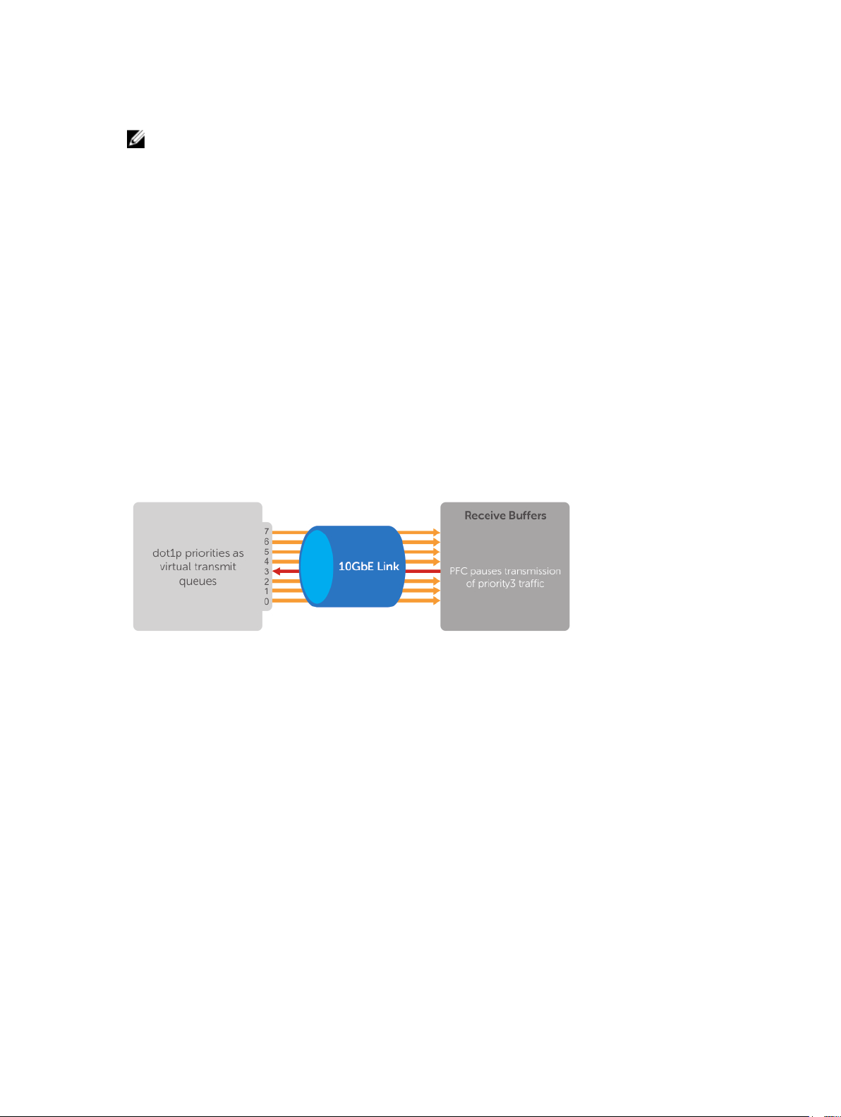
• Data Center Bridging Exchange (DCBx) protocol
NOTE: In Dell Networking OS version 9.4.0.x, only the PFC, ETS, and DCBx features are supported in
data center bridging.
Priority-Based Flow Control
In a data center network, priority-based flow control (PFC) manages large bursts of one traffic type in
multiprotocol links so that it does not affect other traffic types and no frames are lost due to congestion.
When PFC detects congestion on a queue for a specified priority, it sends a pause frame for the 802.1p
priority traffic to the transmitting device. In this way, PFC ensures that large amounts of queued LAN
traffic do not cause storage traffic to be dropped, and that storage traffic does not result in high latency
for high-performance computing (HPC) traffic between servers.
PFC enhances the existing 802.3x pause and 802.1p priority capabilities to enable flow control based on
802.1p priorities (classes of service). Instead of stopping all traffic on a link (as performed by the
traditional Ethernet pause mechanism), PFC pauses traffic on a link according to the 802.1p priority set on
a traffic type. You can create lossless flows for storage and server traffic while allowing for loss in case of
LAN traffic congestion on the same physical interface.
The following illustration shows how PFC handles traffic congestion by pausing the transmission of
incoming traffic with dot1p priority 3.
Figure 1. Priority-Based Flow Control
In the system, PFC is implemented as follows:
• PFC is supported on specified 802.1p priority traffic (dot1p 0 to 7) and is configured per interface.
However, only two lossless queues are supported on an interface: one for Fibre Channel over
Ethernet (FCoE) converged traffic and one for Internet Small Computer System Interface (iSCSI)
storage traffic. Configure the same lossless queues on all ports.
• A dynamic threshold handles intermittent traffic bursts and varies based on the number of PFC
priorities contending for buffers, while a static threshold places an upper limit on the transmit time of
a queue after receiving a message to pause a specified priority. PFC traffic is paused only after
surpassing both static and dynamic thresholds for the priority specified for the port.
• By default, PFC is enabled when you enabled DCB. When you enable DCB globally, you cannot
simultaneously enable TX and RX on the interface for flow control and link-level flow control is
disabled.
• Buffer space is allocated and de-allocated only when you configure a PFC priority on the port.
• PFC delay constraints place an upper limit on the transmit time of a queue after receiving a message
to pause a specified priority.
28
Data Center Bridging (DCB)
Page 29

• By default, PFC is enabled on an interface with no dot1p priorities configured. You can configure the
PFC priorities if the switch negotiates with a remote peer using DCBX. During DCBX negotiation with a
remote peer:
– DCBx communicates with the remote peer by link layer discovery protocol (LLDP) type, length,
value (TLV) to determine current policies, such as PFC support and enhanced transmission
selection (ETS) BW allocation.
– If the negotiation succeeds and the port is in DCBX Willing mode to receive a peer configuration,
PFC parameters from the peer are used to configured PFC priorities on the port. If you enable the
link-level flow control mechanism on the interface, DCBX negotiation with a peer is not
performed.
– If the negotiation fails and PFC is enabled on the port, any user-configured PFC input policies are
applied. If no PFC dcb-map has been previously applied, the PFC default setting is used (no
priorities configured). If you do not enable PFC on an interface, you can enable the 802.3x linklevel pause function. By default, the link-level pause is disabled, when you disable DCBx and PFC.
If no PFC dcb-map has been applied on the interface, the default PFC settings are used.
• PFC supports buffering to receive data that continues to arrive on an interface while the remote
system reacts to the PFC operation.
• PFC uses the DCB MIB IEEE802.1azd2.5 and the PFC MIB IEEE802.1bb-d2.2.
If DCBx negotiation is not successful (for example, due to a version or TLV mismatch), DCBx is disabled
and you cannot enable PFC or ETS.
Configuring Priority-Based Flow Control
PFC provides a flow control mechanism based on the 802.1p priorities in converged Ethernet traffic
received on an interface and is enabled by default when you enable DCB.
As an enhancement to the existing Ethernet pause mechanism, PFC stops traffic transmission for
specified priorities (Class of Service (CoS) values) without impacting other priority classes. Different traffic
types are assigned to different priority classes.
When traffic congestion occurs, PFC sends a pause frame to a peer device with the CoS priority values of
the traffic that is to be stopped. Data Center Bridging Exchange protocol (DCBx) provides the link-level
exchange of PFC parameters between peer devices. PFC allows network administrators to create zeroloss links for Storage Area Network (SAN) traffic that requires no-drop service, while retaining packetdrop congestion management for Local Area Network (LAN) traffic.
To ensure complete no-drop service, apply the same DCB input policy with the same pause time and
dot1p priorities on all PFC-enabled peer interfaces.
To configure PFC and apply a PFC input policy to an interface, follow these steps.
1. Create a DCB input policy to apply pause or flow control for specified priorities using a configured
delay time.
CONFIGURATION mode
dcb-input policy-name
The maximum is 32 alphanumeric characters.
2. Configure the link delay used to pause specified priority traffic.
DCB INPUT POLICY mode
pfc link-delay value
One quantum is equal to a 512-bit transmission.
Data Center Bridging (DCB)
29
Page 30

The range (in quanta) is from 712 to 65535.
The default is 45556 quantum in link delay.
3. Configure the CoS traffic to be stopped for the specified delay.
DCB INPUT POLICY mode
pfc priority priority-range
Enter the 802.1p values of the frames to be paused.
The range is from 0 to 7.
The default is none.
Maximum number of loss less queues supported on the switch: 2.
Separate priority values with a comma. Specify a priority range with a dash, for example: pfc priority
1,3,5-7.
4. Enable the PFC configuration on the port so that the priorities are included in DCBx negotiation with
peer PFC devices.
DCB INPUT POLICY mode
pfc mode on
The default is PFC mode is on.
5. (Optional) Enter a text description of the input policy.
DCB INPUT POLICY mode
description text
The maximum is 32 characters.
6. Exit DCB input policy configuration mode.
DCB INPUT POLICY mode
exit
7. Enter interface configuration mode.
CONFIGURATION mode
interface type slot/port
8. Apply the input policy with the PFC configuration to an ingress interface.
INTERFACE mode
dcb-policy input policy-name
9. Repeat Steps 1 to 8 on all PFC-enabled peer interfaces to ensure lossless traffic service.
Dell Networking OS Behavior: As soon as you apply a DCB policy with PFC enabled on an interface,
DCBx starts exchanging information with PFC-enabled peers. The IEEE802.1Qbb, CEE, and CIN versions
of PFC Type, Length, Value (TLV) are supported. DCBx also validates PFC configurations that are received
in TLVs from peer devices.
30
Data Center Bridging (DCB)
Page 31

By applying a DCB input policy with PFC enabled, you enable PFC operation on ingress port traffic. To
achieve complete lossless handling of traffic, also enable PFC on all DCB egress ports or configure the
dot1p priority-queue assignment of PFC priorities to lossless queues.
To remove a DCB input policy, including the PFC configuration it contains, use the no dcb-input
policy-name command in INTERFACE Configuration mode. To disable PFC operation on an interface,
use the
disabled as the global DCB operation is enabled (dcb enable) or disabled (no dcb enable).
You can enable any number of 802.1p priorities for PFC. Queues to which PFC priority traffic is mapped
are lossless by default. Traffic may be interrupted due to an interface flap (going down and coming up)
when you reconfigure the lossless queues for no-drop priorities in a PFC input policy and reapply the
policy to an interface.
To apply PFC, a PFC peer must support the configured priority traffic (as detected by DCBx).
To honor a PFC pause frame multiplied by the number of PFC-enabled ingress ports, the minimum link
delay must be greater than the round-trip transmission time the peer requres.
If you apply an input policy with PFC disabled (no pfc mode on):
• You can enable link-level flow control on the interface. To delete the input policy, first disable link-
• PFC still allows you to configure lossless queues on a port to ensure no-drop handling of lossless
no pfc mode on command in DCB Input Policy Configuration mode. PFC is enabled and
level flow control. PFC is then automatically enabled on the interface because an interface is by
default PFC-enabled.
traffic.
NOTE: You cannot enable PFC and link-level flow control at the same time on an interface.
When you apply an input policy to an interface, an error message displays if:
• The PFC dot1p priorities result in more than two lossless port queues globally on the switch.
• Link-level flow control is already enabled. You cannot be enable PFC and link-level flow control at the
same time on an interface.
• In a switch stack, configure all stacked ports with the same PFC configuration.
A DCB input policy for PFC applied to an interface may become invalid if you reconfigure dot1p-queue
mapping. This situation occurs when the new dot1p-queue assignment exceeds the maximum number
(2) of lossless queues supported globally on the switch. In this case, all PFC configurations received from
PFC-enabled peers are removed and resynchronized with the peer devices.
Traffic may be interrupted when you reconfigure PFC no-drop priorities in an input policy or reapply the
policy to an interface.
Enhanced Transmission Selection
Enhanced transmission selection (ETS) supports optimized bandwidth allocation between traffic types in
multiprotocol (Ethernet, FCoE, SCSI) links.
ETS allows you to divide traffic according to its 802.1p priority into different priority groups (traffic
classes) and configure bandwidth allocation and queue scheduling for each group to ensure that each
traffic type is correctly prioritized and receives its required bandwidth. For example, you can prioritize
low-latency storage or server cluster traffic in a traffic class to receive more bandwidth and restrict besteffort LAN traffic assigned to a different traffic class.
Data Center Bridging (DCB)
31
Page 32

Although you can configure strict-priority queue scheduling for a priority group, ETS introduces flexibility
that allows the bandwidth allocated to each priority group to be dynamically managed according to the
amount of LAN, storage, and server traffic in a flow. Unused bandwidth is dynamically allocated to
prioritized priority groups. Traffic is queued according to its 802.1p priority assignment, while flexible
bandwidth allocation and the configured queue-scheduling for a priority group is supported.
The following figure shows how ETS allows you to allocate bandwidth when different traffic types are
classed according to 802.1p priority and mapped to priority groups.
Figure 2. Enhanced Transmission Selection
The following table lists the traffic groupings ETS uses to select multiprotocol traffic for transmission.
Table 2. ETS Traffic Groupings
Traffic Groupings Description
Priority group A group of 802.1p priorities used for bandwidth
allocation and queue scheduling. All 802.1p priority
traffic in a group must have the same traffic
handling requirements for latency and frame loss.
Group ID A 4-bit identifier assigned to each priority group.
The range is from 0 to 7.
Group bandwidth Percentage of available bandwidth allocated to a
priority group.
Group transmission selection algorithm (TSA) Type of queue scheduling a priority group uses.
In the Dell Networking OS, ETS is implemented as follows:
• ETS supports groups of 802.1p priorities that have:
– PFC enabled or disabled
– No bandwidth limit or no ETS processing
• Bandwidth allocated by the ETS algorithm is made available after strict-priority groups are serviced. If
a priority group does not use its allocated bandwidth, the unused bandwidth is made available to
32
Data Center Bridging (DCB)
Page 33

other priority groups so that the sum of the bandwidth use is 100%. If priority group bandwidth use
exceeds 100%, all configured priority group bandwidth is decremented based on the configured
percentage ratio until all priority group bandwidth use is 100%. If priority group bandwidth usage is
less than or equal to 100% and any default priority groups exist, a minimum of 1% bandwidth use is
assigned by decreasing 1% of bandwidth from the other priority groups until priority group bandwidth
use is 100%.
• For ETS traffic selection, an algorithm is applied to priority groups using:
– Strict priority shaping
– ETS shaping
– (Credit-based shaping is not supported)
• ETS uses the DCB MIB IEEE 802.1azd2.5.
Configuring Enhanced Transmission Selection
ETS provides a way to optimize bandwidth allocation to outbound 802.1p classes of converged Ethernet
traffic.
Different traffic types have different service needs. Using ETS, you can create groups within an 802.1p
priority class to configure different treatment for traffic with different bandwidth, latency, and best-effort
needs.
For example, storage traffic is sensitive to frame loss; interprocess communication (IPC) traffic is latencysensitive. ETS allows different traffic types to coexist without interruption in the same converged link by:
• Allocating a guaranteed share of bandwidth to each priority group.
• Allowing each group to exceed its minimum guaranteed bandwidth if another group is not fully using
its allotted bandwidth.
To configure ETS and apply an ETS output policy to an interface, you must:
1. Create a Quality of Service (QoS) output policy with ETS scheduling and bandwidth allocation
settings.
2. Create a priority group of 802.1p traffic classes.
3. Configure a DCB output policy in which you associate a priority group with a QoS ETS output policy.
4. Apply the DCB output policy to an interface.
Configuring DCB Maps and its Attributes
This topic contains the following sections that describe how to configure a DCB map, apply the
configured DCB map to a port, configure PFC without a DCB map, and configure lossless queues.
DCB Map: Configuration Procedure
A DCB map consists of PFC and ETS parameters. By default, PFC is not enabled on any 802.1p priority
and ETS allocates equal bandwidth to each priority. To configure user-defined PFC and ETS settings, you
must create a DCB map.
Data Center Bridging (DCB)
33
Page 34

Step Task Command Command Mode
1
Enter global configuration mode to create a
DCB map or edit PFC and ETS settings.
dcb-map name
CONFIGURATION
2
3
Configure the PFC setting (on or off) and the
ETS bandwidth percentage allocated to traffic
in each priority group, or whether the priority
group traffic should be handled with strict
priority scheduling. You can enable PFC on a
maximum of two priority queues on an
interface. Enabling PFC for dot1p priorities
makes the corresponding port queue lossless.
The sum of all allocated bandwidth
percentages in all groups in the DCB map
must be 100%. Strict-priority traffic is serviced
first. Afterwards, bandwidth allocated to other
priority groups is made available and allocated
according to the specified percentages. If a
priority group does not use its allocated
bandwidth, the unused bandwidth is made
available to other priority groups.
Example: priority-group 0 bandwidth 60 pfc
off priority-group 1 bandwidth 20 pfc on
priority-group 2 bandwidth 20 pfc on
priority-group 4 strict-priority pfc off
Repeat this step to configure PFC and ETS
traffic handling for each priority group.
Specify the dot1p priority-to-priority group
mapping for each priority. Priority-group
range: 0 to 7. All priorities that map to the
same queue must be in the same priority
group.
Leave a space between each priority group
number. For example: priority-pgid 0 0 0 1 2
4 4 4 in which priority group 0 maps to dot1p
priorities 0, 1, and 2; priority group 1 maps to
dot1p priority 3; priority group 2 maps to
dot1p priority 4; priority group 4 maps to
dot1p priorities 5, 6, and 7.
priority-group
group_num {bandwidth
percentage | strict-
priority} pfc {on | off}
priority-pgid
dot1p0_group_num
dot1p1_group_num
dot1p2_group_num
dot1p3_group_num
dot1p4_group_num
dot1p5_group_num
dot1p6_group_num
dot1p7_group_num
DCB MAP
DCB MAP
Important Points to Remember
• If you remove a dot1p priority-to-priority group mapping from a DCB map (no priority pgid
command), the PFC and ETS parameters revert to their default values on the interfaces on which the
DCB map is applied. By default, PFC is not applied on specific 802.1p priorities; ETS assigns equal
bandwidth to each 802.1p priority.
As a result, PFC and lossless port queues are disabled on 802.1p priorities, and all priorities are
mapped to the same priority queue and equally share the port bandwidth.
• To change the ETS bandwidth allocation configured for a priority group in a DCB map, do not modify
the existing DCB map configuration. Instead, first create a new DCB map with the desired PFC and
34
Data Center Bridging (DCB)
Page 35

ETS settings, and apply the new map to the interfaces to override the previous DCB map settings.
Then, delete the original dot1p priority-priority group mapping.
If you delete the dot1p priority-priority group mapping (no priority pgid command) before you
apply the new DCB map, the default PFC and ETS parameters are applied on the interfaces. This
change may create a DCB mismatch with peer DCB devices and interrupt network operation.
Applying a DCB Map on a Port
When you apply a DCB map with PFC enabled on an S6000 interface, a memory buffer for PFC-enabled
priority traffic is automatically allocated. The buffer size is allocated according to the number of PFCenabled priorities in the assigned map.
To apply a DCB map to an Ethernet port, follow these steps:
Step Task Command Command Mode
1
Enter interface configuration mode on an
Ethernet port.
interface
{tengigabitEthernet slot/
port |
fortygigabitEthernet
slot/port}
CONFIGURATION
2
Apply the DCB map on the Ethernet port to
configure it with the PFC and ETS settings in
the map; for example:
Dell# interface tengigabitEthernet 0/0
Dell(config-if-te-0/0)# dcb-map
SAN_A_dcb_map1 Repeat Steps 1 and 2 to
apply a DCB map to more than one port.
You cannot apply a DCB map on an interface
that has been already configured for PFC using
thepfc priority command or which is
already configured for lossless queues (pfc
no-drop queues
command).
dcb-map name
INTERFACE
Configuring PFC without a DCB Map
In a network topology that uses the default ETS bandwidth allocation (assigns equal bandwidth to each
priority), you can also enable PFC for specific dot1p-priorities on individual interfaces without using a
DCB map. This type of DCB configuration is useful on interfaces that require PFC for lossless traffic, but
do not transmit converged Ethernet traffic.
Step Task Command Command Mode
1 Enter interface configuration mode on an
Ethernet port.
interface
{tengigabitEthernet
slot/port |
CONFIGURATION
Data Center Bridging (DCB)
35
Page 36

Step Task Command Command Mode
fortygigabitEthernet
slot/port}
2 Enable PFC on specified priorities. Range:
0-7. Default: None.
Maximum number of lossless queues
supported on an Ethernet port: 2.
Separate priority values with a comma.
Specify a priority range with a dash, for
example: pfc priority 3,5-7
1. You cannot configure PFC using the
pfc priority command on an
interface on which a DCB map has been
applied or which is already configured
for lossless queues (pfc no-drop
queues
command).
pfc priority
priority-range
INTERFACE
Configuring Lossless Queues
DCB also supports the manual configuration of lossless queues on an interface after you disable PFC
mode in a DCB map and apply the map on the interface. The configuration of no-drop queues provides
flexibility for ports on which PFC is not needed, but lossless traffic should egress from the interface.
Lossless traffic egresses out the no-drop queues. Ingress 802.1p traffic from PFC-enabled peers is
automatically mapped to the no-drop egress queues.
When configuring lossless queues on a port interface, consider the following points:
• By default, no lossless queues are configured on a port.
• A limit of two lossless queues are supported on a port. If the number of lossless queues configured
exceeds the maximum supported limit per port (two), an error message is displayed. You must reconfigure the value to a smaller number of queues.
• If you configure lossless queues on an interface that already has a DCB map with PFC enabled (pfc
on), an error message is displayed.
Step Task Command Command Mode
1 Enter INTERFACE Configuration mode.
2
3
4
36
Open a DCB map and enter DCB map
configuration mode.
Disable PFC.
Return to interface configuration mode.
interface{tengigabitE
thernet slot/port |
fortygigabitEthernet
slot/port}
dcb-map name
no pfc mode on
exit
CONFIGURATION
INTERFACE
DCB MAP
DCB MAP
Data Center Bridging (DCB)
Page 37

Step Task Command Command Mode
5
Apply the DCB map, created to disable the
PFC operation, on the interface
dcb-map {name |
default}
INTERFACE
6
Configure the port queues that still function
as no-drop queues for lossless traffic.
The maximum number of lossless queues
globally supported on a port is 2.
You cannot configure PFC no-drop queues
on an interface on which a DCB map with
PFC enabled has been applied, or which is
already configured for PFC using the pfc
priority command.
Range: 0-3. Separate queue values with a
comma; specify a priority range with a dash;
for example: pfc no-drop queues 1,3 or pfc
no-drop queues 2-3 Default: No lossless
queues are configured.
pfc no-drop
queuesqueue-range
INTERFACE
Data Center Bridging Exchange Protocol (DCBx)
The data center bridging exchange (DCBx) protocol is disabled by default on any switch on which PFC or
ETS are enabled.
DCBx allows a switch to automatically discover DCB-enabled peers and exchange configuration
information. PFC and ETS use DCBx to exchange and negotiate parameters with peer devices. DCBx
capabilities include:
• Discovery of DCB capabilities on peer-device connections.
• Determination of possible mismatch in DCB configuration on a peer link.
• Configuration of a peer device over a DCB link.
DCBx requires the link layer discovery protocol (LLDP) to provide the path to exchange DCB parameters
with peer devices. Exchanged parameters are sent in organizationally specific TLVs in LLDP data units. For
more information, refer to Link Layer Discovery Protocol (LLDP). The following LLDP TLVs are supported
for DCB parameter exchange:
PFC
parameters
ETS parameters ETS Configuration TLV and ETS Recommendation TLV.
Data Center Bridging (DCB)
PFC Configuration TLV and Application Priority Configuration TLV.
37
Page 38
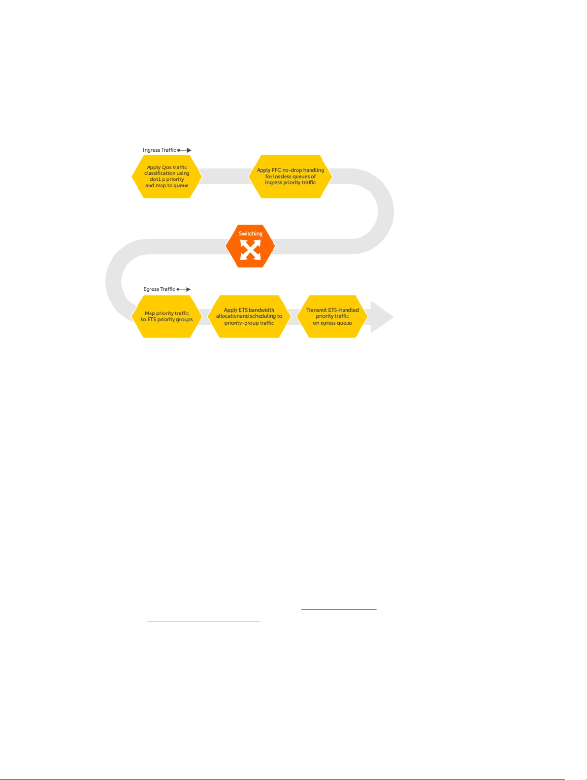
Data Center Bridging in a Traffic Flow
The following figure shows how DCB handles a traffic flow on an interface.
Figure 3. DCB PFC and ETS Traffic Handling
Enabling Data Center Bridging
DCB is automatically configured when you configure FCoE or iSCSI optimization.
Data center bridging supports converged enhanced Ethernet (CEE) in a data center network. DCB is
disabled by default. It must be enabled to support CEE.
• Priority-based flow control
• Enhanced transmission selection
• Data center bridging exchange protocol
• FCoE initialization protocol (FIP) snooping
DCB processes virtual local area network (VLAN)-tagged packets and dot1p priority values. Untagged
packets are treated with a dot1p priority of 0.
For DCB to operate effectively, you can classify ingress traffic according to its dot1p priority so that it
maps to different data queues. The dot1p-queue assignments used are shown in the following table.
To enable DCB, enable either the iSCSI optimization configuration or the FCoE configuration. For
information to configure iSCSI optimization, refer to iSCSI Optimization. For information to configure
FCoE, refer to Fibre Channel over Ethernet.
38
Data Center Bridging (DCB)
Page 39

To enable DCB with PFC buffers on a switch, enter the following commands, save the configuration, and
reboot the system to allow the changes to take effect.
1. Enable DCB.
CONFIGURATION mode
dcb enable
2. Set PFC buffering on the DCB stack unit.
CONFIGURATION mode
dcb stack-unit all pfc-buffering pfc-ports 64 pfc-queues 2
NOTE: To save the pfc buffering configuration changes, save the configuration and reboot the
system.
NOTE: Dell Networking OS Behavior: DCB is not supported if you enable link-level flow control on
one or more interfaces. For more information, refer to Flow Control Using Ethernet Pause Frames.
Data Center Bridging: Auto-DCB-Enable Mode
On an Aggregator in standalone or VLT modes, the default mode of operation for data center bridging on
Ethernet ports is auto-DCB-enable mode. In this mode, Aggregator ports detect whether peer devices
support CEE or not, and enable ETS and PFC or link-level flow control accordingly:
• Interfaces come up with DCB disabled and link-level flow control enabled to control data
transmission between the Aggregator and other network devices (see Flow Control Using Ethernet
Pause Frames). When DCB is disabled on an interface, PFC, and ETS are also disabled.
• When DCBx protocol packets are received, interfaces automatically enable DCB and disable link-level
flow control.
DCB is required for PFC, ETS, DCBx, and FCoE initialization protocol (FIP) snooping to operate.
NOTE: Normally, interfaces do not flap when DCB is automatically enabled.
DCB processes VLAN-tagged packets and dot1p priority values. Untagged packets are treated with a
dot1p priority of 0.
For DCB to operate effectively, ingress traffic is classified according to its dot1p priority so that it maps to
different data queues. The dot1p-queue assignments used on an Aggregator are shown in Table 6-1 in
dcb enable auto-detect on-next-reload Command Example QoS dot1p Traffic Classification and Queue
Assignment.
When DCB is Disabled (Default) By default, Aggregator interfaces operate with DCB disabled and linklevel flow control enabled. When an interface comes up, it is automatically configured with:
• Flow control enabled on input interfaces.
• A DCB-MAP policy is applied with PFC disabled.
The following example shows a default interface configuration with DCB disabled and link-level flow
control enabled.
show interfaces Command Example: DCB disabled and Flow Control enabled
Dell#show running-config interface te 0/4
!
Data Center Bridging (DCB)
39
Page 40

interface TenGigabitEthernet 0/4
mtu 12000
portmode hybrid
switchport
auto vlan
flowcontrol rx on tx off
dcb-map DCB_MAP_PFC_OFF
no keepalive
!
protocol lldp
advertise management-tlv management-address system-name
dcbx port-role auto-downstream
no shutdown
Dell#
When DCB is Enabled When an interface receives a DCBx protocol packet, it automatically enables DCB
and disables link-level flow control. The dcb-map and flow control configurations are removed as shown
in the following example.
show interfaces Command Example: DCB enabled and Flow Control disabled
Dell#show running-config interface te 0/3
!
interface TenGigabitEthernet 0/3
mtu 12000
portmode hybrid
switchport
auto vlan
!
protocol lldp
advertise management-tlv management-address system-name
dcbx port-role auto-downstream
no shutdown
Dell#
When no DCBx TLVs are received on a DCB-enabled interface for 180 seconds, DCB is automatically
disabled and flow control is re-enabled.
Lossless Traffic Handling In auto-DCB-enable mode, Aggregator ports operate with the auto-detection
of DCBx traffic. At any moment, some ports may operate with link-level flow control while others operate
with DCB-based PFC enabled.
As a result, lossless traffic is ensured only if traffic ingresses on a PFC-enabled port and egresses on
another PFC-enabled port.
Lossless traffic is not guaranteed when it is transmitted on a PFC-enabled port and received on a linklevel flow control-enabled port, or transmitted on a link-level flow control-enabled port and received on
a PFC-enabled port.
Enabling DCB on Next Reload To configure the Aggregator so that all interfaces come up with DCB
enabled and flow control disabled, use the dcb enable on-next-reload command. Internal PFC buffers
are automatically configured.
Task Command Command Mode
Globally enable DCB on all
dcb enable on-next-reload CONFIGURATION
interfaces after next switch
reload.
40
Data Center Bridging (DCB)
Page 41

To reconfigure the Aggregator so that all interfaces come up with DCB disabled and link-level flow
control enabled, use the no dcb enable on-next-reload command. PFC buffer memory is
automatically freed.
Enabling Auto-DCB-Enable Mode on Next Reload To configure the Aggregator so that all interfaces
come up in auto-DCB-enable mode with DCB disabled and flow control enabled, use the dcb enable
aut-detect on-next-reload
Task Command Command Mode
command.
Globally enable auto-detection
of DCBx and auto-enabling of
DCB on all interfaces after switch
reload.
Enabling DCB To configure the Aggregator so that all interfaces are DCB enabled and flow control
disabled, use the dcb enable command.
Disabling DCB To configure the Aggregator so that all interfaces are DCB disabled and flow control
enabled, use the no dcb enable command.
dcb enable auto-detect on-next-reload Command Example
Dell#dcb enable auto-detect on-next-reload
dcb enable auto-detect on-next-
reload
CONFIGURATION
QoS dot1p Traffic Classification and Queue Assignment
DCB supports PFC, ETS, and DCBx to handle converged Ethernet traffic that is assigned to an egress
queue according to the following QoS methods:
Honor dot1p dot1p priorities in ingress traffic are used at the port or global switch level.
Layer 2 class
maps
NOTE: Dell Networking does not recommend mapping all ingress traffic to a single queue when
using PFC and ETS. However, Dell Networking does recommend using Ingress traffic classification
using the service-class dynamic dot1p command (honor dot1p) on all DCB-enabled
interfaces. If you use L2 class maps to map dot1p priority traffic to egress queues, take into account
the default dot1p-queue assignments in the following table and the maximum number of two
lossless queues supported on a port.
Although the system allows you to change the default dot1p priority-queue assignments, DCB
policies applied to an interface may become invalid if you reconfigure dot1p-queue mapping. If the
configured DCB policy remains valid, the change in the dot1p-queue assignment is allowed. For
DCB ETS enabled interfaces, traffic destined to queue that is not mapped to any dot1p priority are
dropped.
dot1p priorities are used to classify traffic in a class map and apply a service policy
to an ingress port to map traffic to egress queues.
dot1p Value in the
Incoming Frame
0 0
1 0
Data Center Bridging (DCB)
Egress Queue Assignment
41
Page 42

dot1p Value in the
Incoming Frame
2 0
3 1
4 2
5 3
6 3
7 3
Egress Queue Assignment
How Priority-Based Flow Control is Implemented
Priority-based flow control provides a flow control mechanism based on the 802.1p priorities in
converged Ethernet traffic received on an interface and is enabled by default. As an enhancement to the
existing Ethernet pause mechanism, PFC stops traffic transmission for specified priorities (CoS values)
without impacting other priority classes. Different traffic types are assigned to different priority classes.
When traffic congestion occurs, PFC sends a pause frame to a peer device with the CoS priority values of
the traffic that needs to be stopped. DCBx provides the link-level exchange of PFC parameters between
peer devices. PFC creates zero-loss links for SAN traffic that requires no-drop service, while at the same
time retaining packet-drop congestion management for LAN traffic.
PFC is implemented on an Aggregator as follows:
• If DCB is enabled, as soon as a DCB policy with PFC is applied on an interface, DCBx starts
exchanging information with PFC-enabled peers. The IEEE802.1Qbb, CEE and CIN versions of PFC
TLV are supported. DCBxalso validates PFC configurations received in TLVs from peer devices.
• To achieve complete lossless handling of traffic, enable PFC operation on ingress port traffic and on
all DCB egress port traffic.
• All 802.1p priorities are enabled for PFC. Queues to which PFC priority traffic is mapped are lossless by
default. Traffic may be interrupted due to an interface flap (going down and coming up).
• For PFC to be applied on an Aggregator port, the auto-configured priority traffic must be supported
by a PFC peer (as detected by DCBx).
• A DCB input policy for PFC applied to an interface may become invalid if dot1p-queue mapping is
reconfigured (refer to Create Input Policy Maps). This situation occurs when the new dot1p-queue
assignment exceeds the maximum number (2) of lossless queues supported globally on the switch. In
this case, all PFC configurations received from PFC-enabled peers are removed and re-synchronized
with the peer devices.
• Dell Networking OS does not support MACsec Bypass Capability (MBC).
How Enhanced Transmission Selection is Implemented
Enhanced transmission selection (ETS) provides a way to optimize bandwidth allocation to outbound
802.1p classes of converged Ethernet traffic. Different traffic types have different service needs. Using
ETS, groups within an 802.1p priority class are auto-configured to provide different treatment for traffic
with different bandwidth, latency, and best-effort needs.
For example, storage traffic is sensitive to frame loss; interprocess communication (IPC) traffic is latencysensitive. ETS allows different traffic types to coexist without interruption in the same converged link.
NOTE: The IEEE 802.1Qaz, CEE, and CIN versions of ETS are supported.
42
Data Center Bridging (DCB)
Page 43

ETS is implemented on an Aggregator as follows:
• Traffic in priority groups is assigned to strict-queue or WERR scheduling in an ETS output policy and is
managed using the ETS bandwidth-assignment algorithm. Dell Networking OS de-qeues all frames of
strict-priority traffic before servicing any other queues. A queue with strict-priority traffic can starve
other queues in the same port.
• ETS-assigned bandwidth allocation and scheduling apply only to data queues, not to control queues.
• Dell Networking OS supports hierarchical scheduling on an interface. Dell Networking OS control
traffic is redirected to control queues as higher priority traffic with strict priority scheduling. After
control queues drain out, the remaining data traffic is scheduled to queues according to the
bandwidth and scheduler configuration in the ETS output policy. The available bandwidth calculated
by the ETS algorithm is equal to the link bandwidth after scheduling non-ETS higher-priority traffic.
• By default, equal bandwidth is assigned to each port queue and each dot1p priority in a priority group.
• By default, equal bandwidth is assigned to each priority group in the ETS output policy applied to an
egress port. The sum of auto-configured bandwidth allocation to dot1p priority traffic in all ETS
priority groups is 100%.
• dot1p priority traffic on the switch is scheduled according to the default dot1p-queue mapping. dot1p
priorities within the same queue should have the same traffic properties and scheduling method.
• A priority group consists of 802.1p priority values that are grouped together for similar bandwidth
allocation and scheduling, and that share the same latency and loss requirements. All 802.1p priorities
mapped to the same queue should be in the same priority group.
– By default:
* All 802.1p priorities are grouped in priority group 0.
* 100% of the port bandwidth is assigned to priority group 0. The complete bandwidth is equally
assigned to each priority class so that each class has 12 to 13%.
– The maximum number of priority groups supported in ETS output policies on an interface is equal
to the number of data queues (4) on the port. The 802.1p priorities in a priority group can map to
multiple queues.
• A DCB output policy is created to associate a priority group with an ETS output policy with scheduling
and bandwidth configuration, and applied on egress ports.
– The ETS configuration associated with 802.1p priority traffic in a DCB output policy is used in
DCBx negotiation with ETS peers.
– When an ETS output policy is applied to an interface, ETS-configured scheduling and bandwidth
allocation take precedence over any auto-configured settings in the QoS output policies.
– ETS is enabled by default with the default ETS configuration applied (all dot1p priorities in the same
group with equal bandwidth allocation).
ETS Operation with DCBx
In DCBx negotiation with peer ETS devices, ETS configuration is handled as follows:
• ETS TLVs are supported in DCBx versions CIN, CEE, and IEEE2.5.
• ETS operational parameters are determined by the DCBX port-role configurations.
• ETS configurations received from TLVs from a peer are validated.
• In case of a hardware limitation or TLV error:
– DCBx operation on an ETS port goes down.
– New ETS configurations are ignored and existing ETS configurations are reset to the previously
configured ETS output policy on the port or to the default ETS settings if no ETS output policy was
previously applied.
• ETS operates with legacy DCBx versions as follows:
Data Center Bridging (DCB)
43
Page 44

– In the CEE version, the priority group/traffic class group (TCG) ID 15 represents a non-ETS priority
group. Any priority group configured with a scheduler type is treated as a strict-priority group and
is given the priority-group (TCG) ID 15.
– The CIN version supports two types of strict-priority scheduling:
* Group strict priority: Allows a single priority flow in a priority group to increase its bandwidth
usage to the bandwidth total of the priority group. A single flow in a group can use all the
bandwidth allocated to the group.
* Link strict priority: Allows a flow in any priority group to increase to the maximum link
bandwidth.
CIN supports only the default dot1p priority-queue assignment in a priority group.
Bandwidth Allocation for DCBX CIN
After an ETS output policy is applied to an interface, if the DCBX version used in your data center network
is CIN, a QoS output policy is automatically configured to overwrite the default CIN bandwidth allocation.
This default setting divides the bandwidth allocated to each port queue equally between the dot1p
priority traffic assigned to the queue.
DCBX Operation
The data center bridging exchange protocol (DCBX) is used by DCB devices to exchange configuration
information with directly connected peers using the link layer discovery protocol (LLDP) protocol. DCBX
can detect the misconfiguration of a peer DCB device, and optionally, configure peer DCB devices with
DCB feature settings to ensure consistent operation in a data center network.
DCBX is a prerequisite for using DCB features, such as priority-based flow control (PFC) and enhanced
traffic selection (ETS), to exchange link-level configurations in a converged Ethernet environment. DCBX
is also deployed in topologies that support lossless operation for FCoE or iSCSI traffic. In these scenarios,
all network devices are DCBX-enabled (DCBX is enabled end-to-end).
The following versions of DCBX are supported on an Aggregator: CIN, CEE, and IEEE2.5.
DCBX requires the LLDP to be enabled on all DCB devices.
DCBx Operation
DCBx performs the following operations:
• Discovers DCB configuration (such as PFC and ETS) in a peer device.
• Detects DCB mis-configuration in a peer device; that is, when DCB features are not compatibly
configured on a peer device and the local switch. Mis-configuration detection is feature-specific
because some DCB features support asymmetric configuration.
• Reconfigures a peer device with the DCB configuration from its configuration source if the peer
device is willing to accept configuration.
• Accepts the DCB configuration from a peer if a DCBx port is in “willing” mode to accept a peer’s DCB
settings and then internally propagates the received DCB configuration to its peer ports.
44
Data Center Bridging (DCB)
Page 45

DCBx Port Roles
The following DCBX port roles are auto-configured on an Aggregator to propagate DCB configurations
learned from peer DCBX devices internally to other switch ports:
Auto-upstream The port advertises its own configuration to DCBx peers and receives its
configuration from DCBX peers (ToR or FCF device). The port also propagates its
configuration to other ports on the switch.
The first auto-upstream that is capable of receiving a peer configuration is elected
as the configuration source. The elected configuration source then internally
propagates the configuration to other auto-upstream and auto-downstream ports.
A port that receives an internally propagated configuration overwrites its local
configuration with the new parameter values.
When an auto-upstream port (besides the configuration source) receives and
overwrites its configuration with internally propagated information, one of the
following actions is taken:
• If the peer configuration received is compatible with the internally propagated
port configuration, the link with the DCBx peer is enabled.
• If the received peer configuration is not compatible with the currently
configured port configuration, the link with the DCBX peer port is disabled and
a syslog message for an incompatible configuration is generated. The network
administrator must then reconfigure the peer device so that it advertises a
compatible DCB configuration.
The configuration received from a DCBX peer or from an internally propagated
configuration is not stored in the switch’s running configuration.
Autodownstream
On a DCBX port in an auto-upstream role, the PFC and application priority TLVs are
enabled. ETS recommend TLVs are disabled and ETS configuration TLVs are
enabled.
The port advertises its own configuration to DCBx peers but is not willing to
receive remote peer configuration. The port always accepts internally propagated
configurations from a configuration source. An auto-downstream port that
receives an internally propagated configuration overwrites its local configuration
with the new parameter values.
When an auto-downstream port receives and overwrites its configuration with
internally propagated information, one of the following actions is taken:
• If the peer configuration received is compatible with the internally propagated
port configuration, the link with the DCBx peer is enabled.
• If the received peer configuration is not compatible with the currently
configured port configuration, the link with the DCBX peer port is disabled and
a syslog message for an incompatible configuration is generated. The network
administrator must then reconfigure the peer device so that it advertises a
compatible DCB configuration.
The internally propagated configuration is not stored in the switch’s running
configuration. On a DCBX port in an auto-downstream role, all PFC, application
priority, ETS recommend, and ETS configuration TLVs are enabled.
Data Center Bridging (DCB)
45
Page 46

Default DCBX port role: Uplink ports are auto-configured in an auto-upstream role. Server-facing ports
are auto-configured in an auto-downstream role.
NOTE: On a DCBx port, application priority TLV advertisements are handled as follows:
• The application priority TLV is transmitted only if the priorities in the advertisement match the
configured PFC priorities on the port.
• On auto-upstream and auto-downstream ports:
– If a configuration source is elected, the ports send an application priority TLV based on the
application priority TLV received on the configuration-source port. When an application
priority TLV is received on the configuration-source port, the auto-upstream and autodownstream ports use the internally propagated PFC priorities to match against the received
application priority. Otherwise, these ports use their locally configured PFC priorities in
application priority TLVs.
– If no configuration source is configured, auto-upstream and auto-downstream ports check
to see that the locally configured PFC priorities match the priorities in a received application
priority TLV.
• On manual ports, an application priority TLV is advertised only if the priorities in the TLV match
the PFC priorities configured on the port.
DCB Configuration Exchange
On an Aggregator, the DCBX protocol supports the exchange and propagation of configuration
information for the following DCB features.
• Enhanced transmission selection (ETS)
• Priority-based flow control (PFC)
DCBx uses the following methods to exchange DCB configuration parameters:
Asymmetric DCB parameters are exchanged between a DCBx-enabled port and a peer port
without requiring that a peer port and the local port use the same configured
values for the configurations to be compatible. For example, ETS uses an
asymmetric exchange of parameters between DCBx peers.
Symmetric DCB parameters are exchanged between a DCBx-enabled port and a peer port but
requires that each configured parameter value be the same for the configurations
in order to be compatible. For example, PFC uses an symmetric exchange of
parameters between DCBx peers.
Configuration Source Election
When an auto-upstream or auto-downstream port receives a DCB configuration from a peer, the port
first checks to see if there is an active configuration source on the switch.
• If a configuration source already exists, the received peer configuration is checked against the local
port configuration. If the received configuration is compatible, the DCBx marks the port as DCBxenabled. If the configuration received from the peer is not compatible, a warning message is logged
and the DCBx frame error counter is incremented. Although DCBx is operationally disabled, the port
keeps the peer link up and continues to exchange DCBx packets. If a compatible peer configuration is
later received, DCBx is enabled on the port.
• If there is no configuration source, a port may elect itself as the configuration source. A port may
become the configuration source if the following conditions exist:
46
Data Center Bridging (DCB)
Page 47

– No other port is the configuration source.
– The port role is auto-upstream.
– The port is enabled with link up and DCBx enabled.
– The port has performed a DCBx exchange with a DCBx peer.
– The switch is capable of supporting the received DCB configuration values through either a
symmetric or asymmetric parameter exchange.
A newly elected configuration source propagates configuration changes received from a peer to the
other auto-configuration ports. Ports receiving auto-configuration information from the configuration
source ignore their current settings and use the configuration source information.
Propagation of DCB Information
When an auto-upstream or auto-downstream port receives a DCB configuration from a peer, the port
acts as a DCBx client and checks if a DCBx configuration source exists on the switch.
• If a configuration source is found, the received configuration is checked against the currently
configured values that are internally propagated by the configuration source. If the local configuration
is compatible with the received configuration, the port is enabled for DCBx operation and
synchronization.
• If the configuration received from the peer is not compatible with the internally propagated
configuration used by the configuration source, the port is disabled as a client for DCBx operation and
synchronization and a syslog error message is generated. The port keeps the peer link up and
continues to exchange DCBx packets. If a compatible configuration is later received from the peer,
the port is enabled for DCBx operation.
NOTE: When a configuration source is elected, all auto-upstream ports other than the configuration
source are marked as willing disabled. The internally propagated DCB configuration is refreshed on
all auto-configuration ports and each port may begin configuration negotiation with a DCBx peer
again.
Auto-Detection of the DCBx Version
The Aggregator operates in auto-detection mode so that a DCBX port automatically detects the DCBX
version on a peer port. Legacy CIN and CEE versions are supported in addition to the standard IEEE
version 2.5 DCBX.
A DCBx port detects a peer version after receiving a valid frame for that version. The local DCBx port
reconfigures to operate with the peer version and maintains the peer version on the link until one of the
following conditions occurs:
• The switch reboots.
• The link is reset (goes down and up).
• The peer times out.
• Multiple peers are detected on the link.
DCBX operations on a port are performed according to the auto-configured DCBX version, including fast
and slow transmit timers and message formats. If a DCBX frame with a different version is received, a
syslog message is generated and the peer version is recorded in the peer status table. If the frame cannot
be processed, it is discarded and the discard counter is incremented.
Data Center Bridging (DCB)
47
Page 48

DCBX Example
The following figure shows how DCBX is used on an Aggregator installed in a Dell PowerEdge M I/O
Aggregator chassis in which servers are also installed.
The external 40GbE ports on the base module (ports 33 and 37) of two switches are used for uplinks
configured as DCBx auto-upstream ports. The Aggregator is connected to third-party, top-of-rack (ToR)
switches through 40GbE uplinks. The ToR switches are part of a Fibre Channel storage network.
The internal ports (ports 1-32) connected to the 10GbE backplane are configured as auto-downstream
ports.
On the Aggregator, PFC and ETS use DCBX to exchange link-level configuration with DCBX peer devices.
Figure 4. DCBx Sample Topology
48
Data Center Bridging (DCB)
Page 49

DCBX Prerequisites and Restrictions
The following prerequisites and restrictions apply when you configure DCBx operation on a port:
• DCBX requires LLDP in both send (TX) and receive (RX) mode to be enabled on a port interface. If
multiple DCBX peer ports are detected on a local DCBX interface, LLDP is shut down.
• The CIN version of DCBx supports only PFC, ETS, and FCOE; it does not support iSCSI, backward
congestion management (BCN), logical link down (LLD), and network interface virtualization (NIV).
DCBX Error Messages
The following syslog messages appear when an error in DCBx operation occurs.
LLDP_MULTIPLE_PEER_DETECTED: DCBx is operationally disabled after detecting
more than one DCBx
peer on the port interface.
LLDP_PEER_AGE_OUT: DCBx is disabled as a result of LLDP timing out on a DCBx
peer interface.
DSM_DCBx_PEER_VERSION_CONFLICT: A local port expected to receive the IEEE, CIN,
or CEE version
in a DCBx TLV from a remote peer but received a different, conflicting DCBx
version.
DSM_DCBx_PFC_PARAMETERS_MATCH and DSM_DCBx_PFC_PARAMETERS_MISMATCH: A local
DCBx port received
a compatible (match) or incompatible (mismatch) PFC configuration from a peer.
DSM_DCBx_ETS_PARAMETERS_MATCH and DSM_DCBx_ETS_PARAMETERS_MISMATCH: A local
DCBx port received
a compatible (match) or incompatible (mismatch) ETS configuration from a peer.
LLDP_UNRECOGNISED_DCBx_TLV_RECEIVED: A local DCBx port received an unrecognized
DCBx TLV from
a peer.
Debugging DCBX on an Interface
To enable DCBx debug traces for all or a specific control paths, use the following command.
• Enable DCBx debugging.
EXEC PRIVILEGE mode
debug dcbx {all | auto-detect-timer | config-exchng | fail | mgmt | resource
| sem | tlv}
– all: enables all DCBx debugging operations.
– auto-detect-timer: enables traces for DCBx auto-detect timers.
– config-exchng: enables traces for DCBx configuration exchanges.
– fail: enables traces for DCBx failures.
– mgmt: enables traces for DCBx management frames.
– resource: enables traces for DCBx system resource frames.
– sem: enables traces for the DCBx state machine.
Data Center Bridging (DCB)
49
Page 50

– tlv: enables traces for DCBx TLVs.
Verifying the DCB Configuration
To display DCB configurations, use the following show commands.
Table 3. Displaying DCB Configurations
Command Output
show dcb [stack-unit unit-number]
show interface
statistics
show interface port-type slot/port pfc
{summary | detail}
port-type slot/port pfc
Displays the data center bridging status, number of
PFC-enabled ports, and number of PFC-enabled
queues. On the master switch in a stack, you can
specify a stack-unit number. The range is from 0 to
5.
Displays counters for the PFC frames received and
transmitted (by dot1p priority class) on an interface.
Displays the PFC configuration applied to ingress
traffic on an interface, including priorities and link
delay.
To clear PFC TLV counters, use the clear pfc
counters {stack-unit unit-number |
tengigabitethernet slot/port} command.
show interface
{summary | detail}
Example of the show dcb Command
Dell# show dcb
stack-unit 0 port-set 0
DCB Status : Enabled
PFC Queue Count : 2
Total Buffer[lossy + lossless] (in KB) : 3822
PFC Total Buffer (in KB) : 1912
PFC Shared Buffer (in KB) : 832
PFC Available Buffer (in KB) : 1080
Example of the show interface pfc statistics Command
Dell#show interfaces tengigabitethernet 0/3 pfc statistics
Interface TenGigabitEthernet 0/3
Priority Rx XOFF Frames Rx Total Frames Tx Total Frames
-------------------------------------------------------
0 0 0 0
1 0 0 0
2 0 0 0
3 0 0 0
4 0 0 0
5 0 0 0
port-type slot/port ets
Displays the ETS configuration applied to egress
traffic on an interface, including priority groups
with priorities and bandwidth allocation.
To clear ETS TLV counters, enter the clear ets
counters stack-unit unit-number
command.
50
Data Center Bridging (DCB)
Page 51

6 0 0 0
7 0 0 0
Example of the show interfaces pfc summary Command
Dell# show interfaces tengigabitethernet 0/4 pfc summary
Interface TenGigabitEthernet 0/4
Admin mode is on
Admin is enabled
Remote is enabled, Priority list is 4
Remote Willing Status is enabled
Local is enabled
Oper status is Recommended
PFC DCBx Oper status is Up
State Machine Type is Feature
TLV Tx Status is enabled
PFC Link Delay 45556 pause quantams
Application Priority TLV Parameters :
--------------------------------------
FCOE TLV Tx Status is disabled
ISCSI TLV Tx Status is disabled
Local FCOE PriorityMap is 0x8
Local ISCSI PriorityMap is 0x10
Remote FCOE PriorityMap is 0x8
Remote ISCSI PriorityMap is 0x8
Dell# show interfaces tengigabitethernet 0/4 pfc detail
Interface TenGigabitEthernet 0/4
Admin mode is on
Admin is enabled
Remote is enabled
Remote Willing Status is enabled
Local is enabled
Oper status is recommended
PFC DCBx Oper status is Up
State Machine Type is Feature
TLV Tx Status is enabled
PFC Link Delay 45556 pause quanta
Application Priority TLV Parameters :
--------------------------------------
FCOE TLV Tx Status is disabled
ISCSI TLV Tx Status is disabled
Local FCOE PriorityMap is 0x8
Local ISCSI PriorityMap is 0x10
Remote FCOE PriorityMap is 0x8
Remote ISCSI PriorityMap is 0x8
0 Input TLV pkts, 1 Output TLV pkts, 0 Error pkts, 0 Pause Tx pkts, 0 Pause Rx
pkts
2 Input Appln Priority TLV pkts, 0 Output Appln Priority TLV pkts, 0 Error
Appln Priority TLV Pkts
The following table describes the show interface pfc summary command fields.
Table 4. show interface pfc summary Command Description
Fields Description
Interface Interface type with stack-unit and port number.
Admin mode is on; Admin is enabled PFC Admin mode is on or off with a list of the
configured PFC priorities . When PFC admin mode
Data Center Bridging (DCB)
51
Page 52

Fields Description
is on, PFC advertisements are enabled to be sent
and received from peers; received PFC
configuration takes effect. The admin operational
status for a DCBx exchange of PFC configuration is
enabled or disabled.
Remote is enabled; Priority list Remote Willing
Status is enabled
Operational status (enabled or disabled) of peer
device for DCBx exchange of PFC configuration
with a list of the configured PFC priorities. Willing
status of peer device for DCBx exchange (Willing
bit received in PFC TLV): enabled or disabled.
Local is enabled DCBx operational status (enabled or disabled) with
a list of the configured PFC priorities.
Operational status (local port)
Port state for current operational PFC
configuration:
• Init: Local PFC configuration parameters were
exchanged with peer.
• Recommend: Remote PFC configuration
parameters were received from peer.
• Internally propagated: PFC configuration
parameters were received from configuration
source.
PFC DCBx Oper status Operational status for exchange of PFC
configuration on local port: match (up) or
mismatch (down).
State Machine Type Type of state machine used for DCBx exchanges of
PFC parameters:
• Feature: for legacy DCBx versions
• Symmetric: for an IEEE version
TLV Tx Status Status of PFC TLV advertisements: enabled or
disabled.
PFC Link Delay Link delay (in quanta) used to pause specified
priority traffic.
Application Priority TLV: FCOE TLV Tx Status Status of FCoE advertisements in application
priority TLVs from local DCBx port: enabled or
disabled.
Application Priority TLV: ISCSI TLV Tx Status Status of ISCSI advertisements in application
priority TLVs from local DCBx port: enabled or
disabled.
Application Priority TLV: Local FCOE Priority Map Priority bitmap used by local DCBx port in FCoE
advertisements in application priority TLVs.
Application Priority TLV: Local ISCSI Priority Map Priority bitmap used by local DCBx port in ISCSI
advertisements in application priority TLVs.
52
Data Center Bridging (DCB)
Page 53

Fields Description
Application Priority TLV: Remote FCOE Priority
Map
Priority bitmap received from the remote DCBX
port in FCoE advertisements in application priority
TLVs.
Application Priority TLV: Remote ISCSI Priority Map Priority bitmap received from the remote DCBX
port in iSCSI advertisements in application priority
TLVs.
PFC TLV Statistics: Input TLV pkts Number of PFC TLVs received.
PFC TLV Statistics: Output TLV pkts Number of PFC TLVs transmitted.
PFC TLV Statistics: Error pkts Number of PFC error packets received.
PFC TLV Statistics: Pause Tx pkts Number of PFC pause frames transmitted.
PFC TLV Statistics: Pause Rx pkts Number of PFC pause frames received.
Input Appln Priority TLV pkts Number of Application Priority TLVs received.
Output Appln Priority TLV pkts Number of Application Priority TLVs transmitted.
Error Appln Priority TLV pkts Number of Application Priority error packets
received.
Example of the show interface ets summary Command
Dell# show interfaces te 0/0 ets summary
Interface TenGigabitEthernet 0/0
Max Supported TC Groups is 4
Number of Traffic Classes is 8
Admin mode is on
Admin Parameters :
-----------------Admin is enabled
TC-grp Priority# Bandwidth TSA
0 0,1,2,3,4,5,6,7 100% ETS
1 0% ETS
2 0% ETS
3 0% ETS
4 0% ETS
5 0% ETS
6 0% ETS
7 0% ETS
Priority# Bandwidth TSA
0 13% ETS
1 13% ETS
2 13% ETS
3 13% ETS
4 12% ETS
5 12% ETS
6 12% ETS
7 12% ETS
Remote Parameters:
------------------Remote is disabled
Data Center Bridging (DCB)
53
Page 54

Local Parameters :
-----------------Local is enabled
TC-grp Priority# Bandwidth TSA
0 0,1,2,3,4,5,6,7 100% ETS
1 0% ETS
2 0% ETS
3 0% ETS
4 0% ETS
5 0% ETS
6 0% ETS
7 0% ETS
Priority# Bandwidth TSA
0 13% ETS
1 13% ETS
2 13% ETS
3 13% ETS
4 12% ETS
5 12% ETS
6 12% ETS
7 12% ETS
Oper status is init
Conf TLV Tx Status is disabled
Traffic Class TLV Tx Status is disabled
Example of the show interface ets detail Command
Dell# show interfaces tengigabitethernet 0/4 ets detail
Interface TenGigabitEthernet 0/4
Max Supported TC Groups is 4
Number of Traffic Classes is 8
Admin mode is on
Admin Parameters :
-----------------Admin is enabled
TC-grp Priority# Bandwidth TSA
0 0,1,2,3,4,5,6,7 100% ETS
1 0% ETS
2 0% ETS
3 0% ETS
4 0% ETS
5 0% ETS
6 0% ETS
7 0% ETS
Remote Parameters:
------------------Remote is disabled
Local Parameters :
-----------------Local is enabled
PG-grp Priority# Bandwidth TSA
0 0,1,2,3,4,5,6,7 100% ETS
1 0% ETS
2 0% ETS
3 0% ETS
4 0% ETS
5 0% ETS
6 0% ETS
54
Data Center Bridging (DCB)
Page 55

7 0% ETS
Oper status is init
ETS DCBX Oper status is Down
State Machine Type is Asymmetric
Conf TLV Tx Status is enabled
Reco TLV Tx Status is enabled
0 Input Conf TLV Pkts, 0 Output Conf TLV Pkts, 0 Error Conf TLV Pkts
0 Input Reco TLV Pkts, 0 Output Reco TLV Pkts, 0 Error Reco TLV Pkts
The following table describes the show interface ets detail command fields.
Table 5. show interface ets detail Command Description
Field Description
Interface Interface type with stack-unit and port number.
Max Supported TC Group Maximum number of priority groups supported.
Number of Traffic Classes Number of 802.1p priorities currently configured.
Admin mode ETS mode: on or off.
When on, the scheduling and bandwidth allocation
configured in an ETS output policy or received in a
DCBx TLV from a peer can take effect on an
interface.
Admin Parameters ETS configuration on local port, including priority
groups, assigned dot1p priorities, and bandwidth
allocation.
Remote Parameters ETS configuration on remote peer port, including
Admin mode (enabled if a valid TLV was received
or disabled), priority groups, assigned dot1p
priorities, and bandwidth allocation. If the ETS
Admin mode is enabled on the remote port for
DCBx exchange, the Willing bit received in ETS
TLVs from the remote peer is included.
Local Parameters ETS configuration on local port, including Admin
mode (enabled when a valid TLV is received from a
peer), priority groups, assigned dot1p priorities, and
bandwidth allocation.
Operational status (local port) Port state for current operational ETS
configuration:
• Init: Local ETS configuration parameters were
exchanged with peer.
• Recommend: Remote ETS configuration
parameters were received from peer.
• Internally propagated: ETS configuration
parameters were received from configuration
source.
Data Center Bridging (DCB)
55
Page 56

Field Description
ETS DCBx Oper status Operational status of ETS configuration on local
port: match or mismatch.
State Machine Type Type of state machine used for DCBx exchanges of
ETS parameters:
• Feature: for legacy DCBx versions
• Asymmetric: for an IEEE version
Conf TLV Tx Status Status of ETS Configuration TLV advertisements:
enabled or disabled.
Reco TLV Tx Status Status of ETS Recommendation TLV
advertisements: enabled or disabled.
Input Conf TLV pktsOutput Conf TLV pktsError
Conf TLV pkts
Number of ETS Configuration TLVs received and
transmitted, and number of ETS Error
Configuration TLVs received.
Input Reco TLV pktsOutput Reco TLV pktsError
Reco TLV pkts
Number of ETS Recommendation TLVs received
and transmitted, and number of ETS Error
Recommendation TLVs received.
Example of the show stack-unit all stack-ports all pfc details Command
Dell# show stack-unit all stack-ports all pfc details
stack unit 0 stack-port all
Admin mode is On
Admin is enabled, Priority list is 4-5
Local is enabled, Priority list is 4-5
Link Delay 45556 pause quantum
0 Pause Tx pkts, 0 Pause Rx pkts
stack unit 1 stack-port all
Admin mode is On
Admin is enabled, Priority list is 4-5
Local is enabled, Priority list is 4-5
Link Delay 45556 pause quantum
0 Pause Tx pkts, 0 Pause Rx pkts
Example of the show stack-unit all stack-ports all ets details Command
Dell# show stack-unit all stack-ports all ets details
Stack unit 0 stack port all
Max Supported TC Groups is 4
Number of Traffic Classes is 1
Admin mode is on
Admin Parameters:
-------------------Admin is enabled
TC-grp Priority# Bandwidth TSA
-----------------------------------------------0 0,1,2,3,4,5,6,7 100% ETS
1 - -
56
Data Center Bridging (DCB)
Page 57

2 - 3 - 4 - 5 - 6 - 7 - 8 - -
Stack unit 1 stack port all
Max Supported TC Groups is 4
Number of Traffic Classes is 1
Admin mode is on
Admin Parameters:
-------------------Admin is enabled
TC-grp Priority# Bandwidth TSA
-----------------------------------------------0 0,1,2,3,4,5,6,7 100% ETS
1 - 2 - 3 - 4 - 5 - 6 - 7 - 8 - -
Example of the show interface DCBx detail Command
Dell# show interface tengigabitethernet 0/4 dcbx detail
Dell#show interface te 0/4 dcbx detail
E-ETS Configuration TLV enabled e-ETS Configuration TLV disabled
R-ETS Recommendation TLV enabled r-ETS Recommendation TLV disabled
P-PFC Configuration TLV enabled p-PFC Configuration TLV disabled
F-Application priority for FCOE enabled f-Application Priority for FCOE
disabled
I-Application priority for iSCSI enabled i-Application Priority for iSCSI
disabled
--------------------------------------------------------------------------------
--
Interface TenGigabitEthernet 0/4
Remote Mac Address 00:00:00:00:00:11
Port Role is Auto-Upstream
DCBX Operational Status is Enabled
Is Configuration Source? TRUE
Local DCBX Compatibility mode is CEE
Local DCBX Configured mode is CEE
Peer Operating version is CEE
Local DCBX TLVs Transmitted: ErPfi
Local DCBX Status
---------------- DCBX Operational Version is 0
DCBX Max Version Supported is 0
Sequence Number: 2
Acknowledgment Number: 2
Protocol State: In-Sync
Data Center Bridging (DCB)
57
Page 58

Peer DCBX Status:
--------------- DCBX Operational Version is 0
DCBX Max Version Supported is 255
Sequence Number: 2
Acknowledgment Number: 2
2 Input PFC TLV pkts, 3 Output PFC TLV pkts, 0 Error PFC pkts, 0 PFC Pause Tx
pkts,
0 Pause Rx pkts
2 Input PG TLV Pkts, 3 Output PG TLV Pkts, 0 Error PG TLV Pkts
2 Input Appln Priority TLV pkts, 0 Output Appln Priority TLV pkts, 0 Error
Appln Priority
TLV Pkts
Total DCBX Frames transmitted 27
Total DCBX Frames received 6
Total DCBX Frame errors 0
Total DCBX Frames unrecognized 0
The following table describes the show interface DCBx detail command fields.
Table 6. show interface DCBx detail Command Description
Field Description
Interface Interface type with chassis slot and port number.
Port-Role Configured DCBx port role: auto-upstream or
auto-downstream.
DCBx Operational Status Operational status (enabled or disabled) used to
elect a configuration source and internally
propagate a DCB configuration. The DCBx
operational status is the combination of PFC and
ETS operational status.
Configuration Source Specifies whether the port serves as the DCBx
configuration source on the switch: true (yes) or
false (no).
Local DCBx Compatibility mode DCBx version accepted in a DCB configuration as
compatible. In auto-upstream mode, a port can
only received a DCBx version supported on the
remote peer.
Local DCBx Configured mode DCBx version configured on the port: CEE, CIN,
IEEE v2.5, or Auto (port auto-configures to use the
DCBx version received from a peer).
Peer Operating version DCBx version that the peer uses to exchange DCB
parameters.
Local DCBx TLVs Transmitted Transmission status (enabled or disabled) of
advertised DCB TLVs (see TLV code at the top of
the show command output).
Local DCBx Status: DCBx Operational Version DCBx version advertised in Control TLVs.
Local DCBx Status: DCBx Max Version Supported Highest DCBx version supported in Control TLVs.
Local DCBx Status: Sequence Number Sequence number transmitted in Control TLVs.
58
Data Center Bridging (DCB)
Page 59

Field Description
Local DCBx Status: Acknowledgment Number Acknowledgement number transmitted in Control
TLVs.
Local DCBx Status: Protocol State Current operational state of DCBx protocol: ACK
or IN-SYNC.
Peer DCBx Status: DCBx Operational Version DCBx version advertised in Control TLVs received
from peer device.
Peer DCBx Status: DCBx Max Version Supported Highest DCBx version supported in Control TLVs
received from peer device.
Peer DCBx Status: Sequence Number Sequence number transmitted in Control TLVs
received from peer device.
Peer DCBx Status: Acknowledgment Number Acknowledgement number transmitted in Control
TLVs received from peer device.
Total DCBx Frames transmitted Number of DCBx frames sent from local port.
Total DCBx Frames received Number of DCBx frames received from remote
peer port.
Total DCBx Frame errors Number of DCBx frames with errors received.
Total DCBx Frames unrecognized Number of unrecognizable DCBx frames received.
PFC TLV Statistics: Input PFC TLV pkts Number of PFC TLVs received.
PFC TLV Statistics: Output PFC TLV pkts Number of PFC TLVs transmitted.
PFC TLV Statistics: Error PFC pkts Number of PFC error packets received.
PFC TLV Statistics: PFC Pause Tx pkts Number of PFC pause frames transmitted.
PFC TLV Statistics: PFC Pause Rx pkts Number of PFC pause frames received.
PG TLV Statistics: Input PG TLV Pkts Number of PG TLVs received.
PG TLV Statistics: Output PG TLV Pkts Number of PG TLVs transmitted.
PG TLV Statistics: Error PG TLV Pkts Number of PG error packets received.
Application Priority TLV Statistics: Input Appln
Priority TLV pkts
Application Priority TLV Statistics: Output Appln
Priority TLV pkts
Application Priority TLV Statistics: Error Appln
Priority TLV Pkts
Number of Application TLVs received.
Number of Application TLVs transmitted.
Number of Application TLV error packets received.
Hierarchical Scheduling in ETS Output Policies
ETS supports up to three levels of hierarchical scheduling.
For example, you can apply ETS output policies with the following configurations:
Data Center Bridging (DCB)
59
Page 60

Priority group 1 Assigns traffic to one priority queue with 20% of the link bandwidth and strict-
priority scheduling.
Priority group 2 Assigns traffic to one priority queue with 30% of the link bandwidth.
Priority group 3 Assigns traffic to two priority queues with 50% of the link bandwidth and strict-
priority scheduling.
In this example, the configured ETS bandwidth allocation and scheduler behavior is as follows:
Unused
bandwidth
usage:
Normally, if there is no traffic or unused bandwidth for a priority group, the
bandwidth allocated to the group is distributed to the other priority groups
according to the bandwidth percentage allocated to each group. However, when
three priority groups with different bandwidth allocations are used on an interface:
• If priority group 3 has free bandwidth, it is distributed as follows: 20% of the free
bandwidth to priority group 1 and 30% of the free bandwidth to priority group 2.
• If priority group 1 or 2 has free bandwidth, (20 + 30)% of the free bandwidth is
distributed to priority group 3. Priority groups 1 and 2 retain whatever free
bandwidth remains up to the (20+ 30)%.
Strict-priority
groups:
If two priority groups have strict-priority scheduling, traffic assigned from the
priority group with the higher priority-queue number is scheduled first. However,
when three priority groups are used and two groups have strict-priority scheduling
(such as groups 1 and 3 in the example), the strict priority group whose traffic is
mapped to one queue takes precedence over the strict priority group whose traffic
is mapped to two queues.
Therefore, in this example, scheduling traffic to priority group 1 (mapped to one strict-priority queue)
takes precedence over scheduling traffic to priority group 3 (mapped to two strict-priority queues).
60
Data Center Bridging (DCB)
Page 61

5
Dynamic Host Configuration Protocol (DHCP)
The Aggregator is auto-configured to operate as a DHCP client. The DHCP server, DHCP relay agent, and
secure DHCP features are not supported.The dynamic host configuration protocol (DHCP) is an
application layer protocol that dynamically assigns IP addresses and other configuration parameters to
network end-stations (hosts) based on configuration policies determined by network administrators.
DHCP relieves network administrators of manually configuring hosts, which can be a tedious and errorprone process when hosts often join, leave, and change locations on the network and it reclaims IP
addresses that are no longer in use to prevent address exhaustion.
DHCP is based on a client-server model. A host discovers the DHCP server and requests an IP address,
and the server either leases or permanently assigns one. There are three types of devices that are involved
in DHCP negotiation:
DHCP Server This is a network device offering configuration parameters to the client.
DHCP Client This is a network device requesting configuration parameters from the server.
Relay Agent This is an intermediary network device that passes DHCP messages between the
client and server when the server is not on the same subnet as the host.
NOTE: The DHCP server and relay agent features are not supported on an Aggregator.
Assigning an IP Address using DHCP
The following section describes DHCP and the client in a network.
When a client joins a network:
1. The client initially broadcasts a DHCPDISCOVER message on the subnet to discover available DHCP
servers. This message includes the parameters that the client requires and might include suggested
values for those parameters.
2. Servers unicast or broadcast a DHCPOFFER message in response to the DHCPDISCOVER that offers
to the client values for the requested parameters. Multiple servers might respond to a single
DHCPDISCOVER; the client might wait a period of time and then act on the most preferred offer.
3. The client broadcasts a DHCPREQUEST message in response to the offer, requesting the offered
values.
4. After receiving a DHCPREQUEST, the server binds the clients’ unique identifier (the hardware address
plus IP address) to the accepted configuration parameters and stores the data in a database called a
binding table. The server then broadcasts a DHCPACK message, which signals to the client that it
may begin using the assigned parameters.
There are additional messages that are used in case the DHCP negotiation deviates from the process
previously described and shown in the illustration below.
Dynamic Host Configuration Protocol (DHCP)
61
Page 62

DHCPDECLINE A client sends this message to the server in response to a DHCPACK if the
configuration parameters are unacceptable; for example, if the offered address is
already in use. In this case, the client starts the configuration process over by
sending a DHCPDISCOVER.
DHCPINFORM A client uses this message to request configuration parameters when it assigned an
IP address manually rather than with DHCP. The server responds by unicast.
DHCPNAK A server sends this message to the client if it is not able to fulfill a DHCPREQUEST;
for example, if the requested address is already in use. In this case, the client starts
the configuration process over by sending a DHCPDISCOVER.
DHCPRELEASE A DHCP client sends this message when it is stopped forcefully to return its IP
address to the server.
Figure 5. Assigning Network Parameters using DHCP
62
Dynamic Host Configuration Protocol (DHCP)
Page 63

Dell Networking OS Behavior: DHCP is implemented in Dell Networking OS based on RFC 2131 and
3046.
Debugging DHCP Client Operation
To enable debug messages for DHCP client operation, enter the following debug commands:
• Enable the display of log messages for all DHCP packets sent and received on DHCP client interfaces.
EXEC Privilege
[no] debug ip dhcp client packets [interface type slot/port]
• Enable the display of log messages for the following events on DHCP client interfaces: IP address
acquisition, IP address release, Renewal of IP address and lease time, and Release of an IP address.
EXEC Privilege
[no] debug ip dhcp client events [interface type slot/port]
The following example shows the packet- and event-level debug messages displayed for the packet
transmissions and state transitions on a DHCP client interface.
DHCP Client: Debug Messages Logged during DHCP Client Enabling/Disabling
Dell (conf-if-Ma-0/0)# ip address dhcp
1w2d23h: %STKUNIT0-M:CP %DHCLIENT-5-DHCLIENT-LOG: DHCLIENT_DBG_EVT: Interface
Ma 0/0 :DHCP ENABLE
CMD
Received in state START
1w2d23h: %STKUNIT0-M:CP %DHCLIENT-5-DHCLIENT-LOG: DHCLIENT_DBG_EVT: Interface
Ma 0/0 :Transitioned
to state SELECTING
1w2d23h: %STKUNIT0-M:CP %DHCLIENT-5-DHCLIENT-LOG: DHCLIENT_DBG_PKT: DHCP
DISCOVER sent in
Interface
Ma 0/0
1w2d23h: %STKUNIT0-M:CP %DHCLIENT-5-DHCLIENT-LOG: DHCLIENT_DBG_PKT: Received
DHCPOFFER packet in
Interface Ma 0/0 with Lease-ip:10.16.134.250, Mask:255.255.0.0,Server-Id:
10.16.134.249
1w2d23h: %STKUNIT0-M:CP %DHCLIENT-5-DHCLIENT-LOG: DHCLIENT_DBG_EVT: Interface
Ma 0/0 :Transitioned
to state REQUESTING
1w2d23h: %STKUNIT0-M:CP %DHCLIENT-5-DHCLIENT-LOG: DHCLIENT_DBG_PKT:DHCP REQUEST
sent in Interface
Ma 0/0
1w2d23h: %STKUNIT0-M:CP %DHCLIENT-5-DHCLIENT-LOG: DHCLIENT_DBG_PKT:Received
DHCPACK packet in
Interface
Ma 0/0 with Lease-IP:10.16.134.250, Mask:255.255.0.0,DHCP REQUEST sent in
Interface Ma 0/0
1w2d23h: %STKUNIT0-M:CP %DHCLIENT-5-DHCLIENT-LOG: DHCLIENT_DBG_EVT: Interface
Ma 0/0 :Transitioned
to state BOUND
Dell(conf-if-ma-0/0)# no ip address
Dell(conf-if-ma-0/0)#1w2d23h: %STKUNIT0-M:CP %DHCLIENT-5-DHCLIENT-LOG:
DHCLIENT_DBG_EVT: Interface
Ma 0/0 :DHCP DISABLE CMD Received in state SELECTING
Dynamic Host Configuration Protocol (DHCP)
63
Page 64

1w2d23h: %STKUNIT0-M:CP %DHCLIENT-5-DHCLIENT-LOG: DHCLIENT_DBG_EVT: Interface
Ma 0/0 :Transitioned
to state START
1w2d23h: %STKUNIT0-M:CP %DHCLIENT-5-DHCLIENT-LOG: DHCLIENT_DBG_EVT: Interface
Ma 0/0 :DHCP DISABLED
CMD
sent to FTOS in state START
Dell# release dhcp int Ma 0/0
Dell#1w2d23h: %STKUNIT0-M:CP %DHCLIENT-5-DHCLIENT-LOG: DHCLIENT_DBG_EVT:
Interface Ma 0/0 :DHCP
RELEASE
CMD Received in state BOUND
1w2d23h: %STKUNIT0-M:CP %DHCLIENT-5-DHCLIENT-LOG: DHCLIENT_DBG_PKT: DHCP
RELEASE sent in Interface
Ma 0/0
1w2d23h: %STKUNIT0-M:CP %DHCLIENT-5-DHCLIENT-LOG: DHCLIENT_DBG_EVT: Interface
Ma 0/0 :Transitioned
to state STOPPED
1w2d23h: %STKUNIT0-M:CP %DHCLIENT-5-DHCLIENT-LOG: DHCLIENT_DBG_EVT: Interface
Ma 0/0 :DHCP IP
RELEASED
CMD sent to FTOS in state STOPPED
Dell# renew dhcp int Ma 0/0
Dell#1w2d23h: %STKUNIT0-M:CP %DHCLIENT-5-DHCLIENT-LOG: DHCLIENT_DBG_EVT:
Interface Ma 0/0 :DHCP
RENEW
CMD Received in state STOPPED
1w2d23h: %STKUNIT0-M:CP %DHCLIENT-5-DHCLIENT-LOG: DHCLIENT_DBG_EVT: Interface
Ma 0/0 :Transitioned
to state SELECTING
1w2d23h: %STKUNIT0-M:CP %DHCLIENT-5-DHCLIENT-LOG: DHCLIENT_DBG_PKT: DHCP
DISCOVER sent in Interface
Ma 0/0
1w2d23h: %STKUNIT0-M:CP %DHCLIENT-5-DHCLIENT-LOG: DHCLIENT_DBG_PKT: Received
DHCPOFFER packet in
Interface Ma 0/0 with Lease-Ip:10.16.134.250, Mask:255.255.0.0,Server-Id:
10.16.134.249
The following example shows the packet- and event-level debug messages displayed for the packet
transmissions and state transitions on a DHCP client interface when you release and renew a DHCP
client.
DHCP Client: Debug Messages Logged during DHCP Client Release/Renew
Dell# release dhcp interface managementethernet 0/0
May 27 15:55:22: %STKUNIT0-M:CP %DHCLIENT-5-DHCLIENT-LOG: DHCLIENT_DBG_EVT:
Interface Ma 0/0 :
DHCP RELEASE CMD Received in state BOUND
May 27 15:55:22: %STKUNIT0-M:CP %DHCLIENT-5-DHCLIENT-LOG: DHCLIENT_DBG_PKT:
DHCP RELEASE sent in Interface Ma 0/0
May 27 15:55:22: %STKUNIT0-M:CP %DHCLIENT-5-DHCLIENT-LOG: DHCLIENT_DBG_EVT:
Interface Ma 0/0 :
Transitioned to state STOPPED
May 27 15:55:22: %STKUNIT0-M:CP %DHCLIENT-5-DHCLIENT-LOG: DHCLIENT_DBG_EVT:
Interface Ma 0/0 :
DHCP IP RELEASED CMD sent to FTOS in state STOPPED
64
Dynamic Host Configuration Protocol (DHCP)
Page 65

Dell# renew dhcp interface tengigabitethernet 0/1
Dell#May 27 15:55:28: %STKUNIT0-M:CP %DHCLIENT-5-DHCLIENT-LOG:
DHCLIENT_DBG_EVT: Interface Ma 0/0 :
DHCP RENEW CMD Received in state STOPPED
May 27 15:55:31: %STKUNIT0-M:CP %DHCLIENT-5-DHCLIENT-LOG: DHCLIENT_DBG_EVT:
Interface Ma 0/0 :
Transitioned to state SELECTING
May 27 15:55:31: %STKUNIT0-M:CP %DHCLIENT-5-DHCLIENT-LOG: DHCLIENT_DBG_PKT:
DHCP DISCOVER sent in Interface Ma 0/0
May 27 15:55:31: %STKUNIT0-M:CP %DHCLIENT-5-DHCLIENT-LOG: DHCLIENT_DBG_PKT:
Received DHCPOFFER packet in Interface Ma 0/0 with Lease-Ip:10.16.134.250,
Mask:255.255.0.0,Server-Id:10.16.134.249
DHCP Client
An Aggregator is auto-configured to operate as a DHCP client. The DHCP client functionality is enabled
only on the default VLAN and the management interface.
A DHCP client is a network device that requests an IP address and configuration parameters from a DHCP
server. On an Aggregator, the DHCP client functionality is implemented as follows:
• The public out-of-band management (OOB) interface and default VLAN 1 are configured, by default,
as a DHCP client to acquire a dynamic IP address from a DHCP server.
You can override the DHCP-assigned address on the OOB management interface by manually
configuring an IP address using the CLI or CMC interface. If no user-configured IP address exists for
the OOB interface exists and if the OOB IP address is not in the startup configuration, the Aggregator
will automatically obtain it using DHCP.
You can also manually configure an IP address for the VLAN 1 default management interface using the
CLI. If no user-configured IP address exists for the default VLAN management interface exists and if
the default VLAN IP address is not in the startup configuration, the Aggregator will automatically
obtain it using DHCP.
• The default VLAN 1 with all ports configured as members is the only L3 interface on the Aggregator.
When the default management VLAN has a DHCP-assigned address and you reconfigure the default
VLAN ID number, the Aggregator:
– Sends a DHCP release to the DHCP server to release the IP address.
– Sends a DHCP request to obtain a new IP address. The IP address assigned by the DHCP server is
used for the new default management VLAN.
How DHCP Client is Implemented
The Aggregator is enabled by default to receive DHCP server-assigned dynamic IP addresses on an
interface. This setting persists after a switch reboot. If you enter the
interface, DHCP transactions are stopped and the dynamically-acquired IP address is saved. Use the
interface type slot/port command to display the dynamic IP address and DHCP as the mode of
IP address assignment. If you later enter the no shutdown command and the lease timer for the
dynamic IP address has expired, the IP address is unconfigured and the interface tries to acquire a new
dynamic address from DHCP server.
If you later enter the no shutdown command and the lease timer for the dynamic IP address has
expired, the IP address is released.
When you enter the release dhcp command, although the IP address that was dynamically-acquired
from a DHCP server is released from an interface, the ability to acquire a new DHCP server-assigned
shutdown command on the
show
Dynamic Host Configuration Protocol (DHCP)
65
Page 66

address remains in the running configuration for the interface. To acquire a new IP address, enter either
the renew dhcp command at the EXEC privilege level or the ip address dhcp command at the
interface configuration level.
If you enter renew dhcp command on an interface already configured with a dynamic IP address, the
lease time of the dynamically acquired IP address is renewed.
Important: To verify the currently configured dynamic IP address on an interface, enter the show
ip dhcp lease command. The show running-configuration command output only displays
ip address dhcp; the currently assigned dynamic IP address is not displayed.
DHCP Client on a Management Interface
These conditions apply when you enable a management interface to operate as a DHCP client.
• The management default route is added with the gateway as the router IP address received in the
DHCP ACK packet. It is required to send and receive traffic to and from other subnets on the external
network. The route is added irrespective when the DHCP client and server are in the same or different
subnets. The management default route is deleted if the management IP address is released like other
DHCP client management routes.
• ip route for 0.0.0.0 takes precedence if it is present or added later.
• Management routes added by a DHCP client display with Route Source as DHCP in the show ip
management route and show ip management-route dynamic command output.
• Management routes added by DHCP are automatically reinstalled if you configure a static IP route
with the ip route command that replaces a management route added by the DHCP client. If you
remove the statically configured IP route using the no ip route command, the management route
is reinstalled. Manually delete management routes added by the DHCP client.
• To reinstall management routes added by the DHCP client that is removed or replaced by the same
statically configured management routes, release the DHCP IP address and renew it on the
management interface.
• Management routes added by the DHCP client have higher precedence over the same statically
configured management route. Static routes are not removed from the running configuration if a
dynamically acquired management route added by the DHCP client overwrites a static management
route.
• Management routes added by the DHCP client are not added to the running configuration.
NOTE: Management routes added by the DHCP client include the specific routes to reach a DHCP
server in a different subnet and the management route.
DHCP Client on a VLAN
The following conditions apply on a VLAN that operates as a DHCP client:
• The default VLAN 1 with all ports auto-configured as members is the only L3 interface on the
Aggregator.
• When the default management VLAN has a DHCP-assigned address and you reconfigure the default
VLAN ID number, the Aggregator:
– Sends a DHCP release to the DHCP server to release the IP address.
– Sends a DHCP request to obtain a new IP address. The IP address assigned by the DHCP server is
used for the new default management VLAN.
66
Dynamic Host Configuration Protocol (DHCP)
Page 67

DHCP Packet Format and Options
DHCP uses the user datagram protocol (UDP) as its transport protocol.
The server listens on port 67 and transmits to port 68; the client listens on port 68 and transmits to port
67. The configuration parameters are carried as options in the DHCP packet in Type, Length, Value (TLV)
format; many options are specified in RFC 2132. To limit the number of parameters that servers must
provide, hosts specify the parameters that they require, and the server sends only those parameters.
Some common options are shown in the following illustration.
Figure 6. DHCP packet Format
The following table lists common DHCP options.
Option Number and Description
Subnet Mask Option 1
Specifies the client’s subnet mask.
Router Option 3
Specifies the router IP addresses that may serve as the client’s default gateway.
Domain Name
Server
Domain Name Option 15
IP Address Lease
Time
DHCP Message
Type
Option 6
Specifies the domain name servers (DNSs) that are available to the client.
Specifies the domain name that clients should use when resolving hostnames via
DNS.
Option 51
Specifies the amount of time that the client is allowed to use an assigned IP
address.
Option 53
• 1: DHCPDISCOVER
• 2: DHCPOFFER
• 3: DHCPREQUEST
• 4: DHCPDECLINE
Dynamic Host Configuration Protocol (DHCP)
67
Page 68

Option Number and Description
• 5: DHCPACK
• 6: DHCPNACK
• 7: DHCPRELEASE
• 8: DHCPINFORM
Parameter Request
List
Renewal Time Option 58
Rebinding Time Option 59
End Option 255
Option 55
Clients use this option to tell the server which parameters it requires. It is a series of
octets where each octet is DHCP option code.
Specifies the amount of time after the IP address is granted that the client attempts
to renew its lease with the original server.
Specifies the amount of time after the IP address is granted that the client attempts
to renew its lease with any server, if the original server does not respond.
Signals the last option in the DHCP packet.
Option 82
RFC 3046 (the relay agent information option, or Option 82) is used for class-based IP address
assignment.
The code for the relay agent information option is 82, and is comprised of two sub-options, circuit ID and
remote ID.
Circuit ID This is the interface on which the client-originated message is received.
Remote ID This identifies the host from which the message is received. The value of this sub-
option is the MAC address of the relay agent that adds Option 82.
The DHCP relay agent inserts Option 82 before forwarding DHCP packets to the server. The server can
use this information to:
• track the number of address requests per relay agent. Restricting the number of addresses available
per relay agent can harden a server against address exhaustion attacks.
• associate client MAC addresses with a relay agent to prevent offering an IP address to a client
spoofing the same MAC address on a different relay agent.
• assign IP addresses according to the relay agent. This prevents generating DHCP offers in response to
requests from an unauthorized relay agent.
The server echoes the option back to the relay agent in its response, and the relay agent can use the
information in the option to forward a reply out the interface on which the request was received rather
than flooding it on the entire VLAN.
The relay agent strips Option 82 from DHCP responses before forwarding them to the client.
To insert Option 82 into DHCP packets, follow this step.
68
Dynamic Host Configuration Protocol (DHCP)
Page 69

• Insert Option 82 into DHCP packets.
CONFIGURATION mode
int ma 0/0
ip add dhcp relay information-option remote-id
For routers between the relay agent and the DHCP server, enter the trust-downstream option.
Releasing and Renewing DHCP-based IP Addresses
On an Aggregator configured as a DHCP client, you can release a dynamically-assigned IP address
without removing the DHCP client operation on the interface.
To manually acquire a new IP address from the DHCP server, use the following command.
• Release a dynamically-acquired IP address while retaining the DHCP client configuration on the
interface.
EXEC Privilege mode
release dhcp interface type slot/port
• Acquire a new IP address with renewed lease time from a DHCP server.
EXEC Privilege mode
renew dhcp interface type slot/port
Viewing DHCP Statistics and Lease Information
To display DHCP client information, enter the following show commands:
• Display statistics about DHCP client interfaces.
EXEC Privilege
show ip dhcp client statistics interface type slot/port
• Clear DHCP client statistics on a specified or on all interfaces.
EXEC Privilege
clear ip dhcp client statistics {all | interface type slot/port}
• Display lease information about the dynamic IP address currently assigned to a DHCP client interface.
EXEC Privilege
show ip dhcp lease [interface type slot/port]
View the statistics about DHCP client interfaces with the show ip dhcp client statistics command and the
lease information about the dynamic IP address currently assigned to a DHCP client interface with the
show ip dhcp lease command.
Example of the show ip dhcp client statistics Command
Dell# show ip dhcp client statistics interface tengigabitethernet 0/0 Interface
Name Ma 0/0
Message Received
DHCPOFFER 0
DHCPACK 0
DHCPNAK 0
Message Sent
DHCPDISCOVER 13
Dynamic Host Configuration Protocol (DHCP)
69
Page 70

DHCPREQUEST 0
DHCPDECLINE 0
DHCPRELEASE 0
DHCPREBIND 0
DHCPRENEW 0
DHCPINFORM 0
Example of the show ip dhcp lease Command
Dell# show ip dhcp
Interface Lease-IP Def-Router ServerId State Lease Obtnd At Lease
Expires At
========= ======== ========= ======== ===== ==============
================ Ma 0/0
0.0.0.0/0 0.0.0.0 0.0.0.0 INIT -----NA----- ----NA----
Vl 1 10.1.1.254/24 0.0.0.0 10.1.1.1 BOUND 08-26-2011 04:33:39
08-27-2011 04:33:39
Renew Time Rebind Time
========== ========
----NA---- ----NA----
08-26-2011 16:21:50 08-27-2011 01:33:39
70
Dynamic Host Configuration Protocol (DHCP)
Page 71

6
FIP Snooping
FIP snooping is auto-configured on an Aggregator in standalone mode. You can display information on
FIP snooping operation and statistics by entering show commands.
This chapter describes about the FIP snooping concepts and configuration procedures.
Fibre Channel over Ethernet
Fibre Channel over Ethernet (FCoE) provides a converged Ethernet network that allows the combination
of storage-area network (SAN) and LAN traffic on a Layer 2 link by encapsulating Fibre Channel data into
Ethernet frames.
FCoE works with Ethernet enhancements provided in data center bridging (DCB) to support lossless (nodrop) SAN and LAN traffic. In addition, DCB provides flexible bandwidth sharing for different traffic types,
such as LAN and SAN, according to 802.1p priority classes of service. For more information, refer to the
Data Center Bridging (DCB) chapter.
Ensuring Robustness in a Converged Ethernet Network
Fibre Channel networks used for SAN traffic employ switches that operate as trusted devices. End devices
log into the switch to which they are attached in order to communicate with the other end devices
attached to the Fibre Channel network. Because Fibre Channel links are point-to-point, a Fibre Channel
switch controls all storage traffic that an end device sends and receives over the network. As a result, the
switch can enforce zoning configurations, ensure that end devices use their assigned addresses, and
secure the network from unauthorized access and denial-of-service attacks.
To ensure similar Fibre Channel robustness and security with FCoE in an Ethernet cloud network, the
Fibre Channel over Ethernet initialization protocol (FIP) establishes virtual point-to-point links between
FCoE end-devices (server ENodes and target storage devices) and FCoE forwarders (FCFs) over transit
FCoE-enabled bridges.
Ethernet bridges commonly provide access control list (ACLs) that can emulate a point-to-point link by
providing the traffic enforcement required to create a Fibre Channel-level of robustness. In addition, FIP
serves as a Layer 2 protocol to:
• Operate between FCoE end-devices and FCFs over intermediate Ethernet bridges to prevent
unauthorized access to the network and achieve the required security.
• Allow transit Ethernet bridges to efficiently monitor FIP frames passing between FCoE end-devices
and an FCF, and use the FIP snooping data to dynamically configure ACLs on the bridge to only
permit traffic authorized by the FCF.
FIP enables FCoE devices to discover one another, initialize and maintain virtual links over an Ethernet
network, and access storage devices in a storage area network. FIP satisfies the Fibre Channel
requirement for point-to-point connections by creating a unique virtual link for each connection
between an FCoE end-device and an FCF via a transit switch.
FIP Snooping
71
Page 72

FIP provides a functionality for discovering and logging in to an FCF. After discovering and logging in, FIP
allows FCoE traffic to be sent and received between FCoE end-devices (ENodes) and the FCF. FIP uses its
own EtherType and frame format. The below illustration about FIP discovery, depicts the communication
that occurs between an ENode server and an FCoE switch (FCF).
FIP performs the following functions:
• FIP virtual local area network (VLAN) discovery: FCoE devices (Enodes) discover the FCoE VLANs on
which to transmit and receive FIP and FCoE traffic.
• FIP discovery: FCoE end-devices and FCFs are automatically discovered.
• Initialization: FCoE devices perform fabric login (FLOGI) and fabric discovery (FDISC) to create a virtual
link with an FCoE switch.
• Maintenance: A valid virtual link between an FCoE device and an FCoE switch is maintained and the
link termination logout (LOGO) functions properly.
Figure 7. FIP discovery and login between an ENode and an FCF
FIP Snooping on Ethernet Bridges
In a converged Ethernet network, intermediate Ethernet bridges can snoop on FIP packets during the
login process on an FCF. Then, using ACLs, a transit bridge can permit only authorized FCoE traffic to be
72
FIP Snooping
Page 73

transmitted between an FCoE end-device and an FCF. An Ethernet bridge that provides these functions is
called a FIP snooping bridge (FSB).
On a FIP snooping bridge, ACLs are created dynamically as FIP login frames are processed. The ACLs are
installed on switch ports configured for the following port modes:
• ENode mode for server-facing ports
• FCF mode for a trusted port directly connected to an FCF
You must enable FIP snooping on an Aggregator and configure the FIP snooping parameters. When you
enable FIP snooping, all ports on the switch by default become ENode ports.
Dynamic ACL generation on an Aggregator operating as a FIP snooping bridge functions as follows:
• Global ACLs are applied on server-facing ENode ports.
• Port-based ACLs are applied on ports directly connected to an FCF and on server-facing ENode ports.
• Port-based ACLs take precedence over global ACLs.
• FCoE-generated ACLs take precedence over user-configured ACLs. A user-configured ACL entry
cannot deny FCoE and FIP snooping frames.
The below illustration depicts an Aggregator used as a FIP snooping bridge in a converged Ethernet
network. The ToR switch operates as an FCF for FCoE traffic. Converged LAN and SAN traffic is
transmitted between the ToR switch and an Aggregator. The Aggregator operates as a lossless FIP
snooping bridge to transparently forward FCoE frames between the ENode servers and the FCF switch.
FIP Snooping
73
Page 74

Figure 8. FIP Snooping on an Aggregator
The following sections describes how to configure the FIP snooping feature on a switch that functions as
a FIP snooping bridge so that it can perform the following functions:
• Performs FIP snooping (allowing and parsing FIP frames) globally on all VLANs or on a per-VLAN basis.
• Set the FCoE MAC address prefix (FC-MAP) value used by an FCF to assign a MAC address to an ECoE
end-device (server ENode or storage device) after a server successfully logs in
• Set the FCF mode to provide additional port security on ports that are directly connected to an FCF.
• Check FIP snooping-enabled VLANs to ensure that they are operationally active.
74
FIP Snooping
Page 75

• Process FIP VLAN discovery requests and responses, advertisements, solicitations, FLOGI/FDISC
requests and responses, FLOGO requests and responses, keep-alive packets, and clear virtual-link
messages.
FIP Snooping in a Switch Stack
FIP snooping supports switch stacking as follows:.
• A switch stack configuration is synchronized with the standby stack unit.
• Dynamic population of the FCoE database (ENode, Session, and FCF tables) is synchronized with the
standby stack unit. The FCoE database is maintained by snooping FIP keep-alive messages.
• In case of a failover, the new master switch starts the required timers for the FCoE database tables.
Timers run only on the master stack unit.
NOTE: While technically possible to run FIP snooping and stacking concurrently, Dell Networking
recommends a SAN design utilizes two redundant FCoE network path versus stacking. This avoids a
single point of failure to the SAN and provides a guaranteed latency. The overall latency could easily
rise above desired SAN limits if a link level failure redirects traffic over the stacking backplane.
How FIP Snooping is Implemented
As soon as the Aggregator is activated in an M1000e chassis as a switch-bridge, existing VLAN-specific
and FIP snooping auto-configurations are applied. The Aggregator snoops FIP packets on VLANs enabled
for FIP snooping and allows legitimate sessions. By default, all FCoE and FIP frames are dropped unless
specifically permitted by existing FIP snooping-generated ACLs.
FIP Snooping on VLANs
FIP snooping is enabled globally on an Aggregator on all VLANs:
• FIP frames are allowed to pass through the switch on the enabled VLANs and are processed to
generate FIP snooping ACLs.
• FCoE traffic is allowed on VLANs only after a successful virtual-link initialization (fabric login FLOGI)
between an ENode and an FCF. All other FCoE traffic is dropped.
• Atleast one interface is auto-configured for FCF (FIP snooping bridge — FCF) mode on a FIP
snooping-enabled VLAN. Multiple FCF trusted interfaces are auto-configured in a VLAN.
• A maximum of eight VLANs are supported for FIP snooping on an Aggregator. FIP snooping processes
FIP packets in traffic only from the first eight incoming VLANs.
FC-MAP Value
The FC-MAP value that is applied globally by the Aggregator on all FCoE VLANs to authorize FCoE traffic
is auto-configured.
The FC-MAP value is used to check the FC-MAP value for the MAC address assigned to ENodes in
incoming FCoE frames. If the FC-MAP values does not match, FCoE frames are dropped. A session
between an ENode and an FCF is established by the switch —bridge only when the FC-MAP value on the
FCF matches the FC-MAP value on the FIP snooping bridge.
FIP Snooping
75
Page 76

Bridge-to-FCF Links
A port directly connected to an FCF is auto-configured in FCF mode. Initially, all FCoE traffic is blocked;
only FIP frames are allowed to pass.
FCoE traffic is allowed on the port only after a successful FLOGI request/response and confirmed use of
the configured FC-MAP value for the VLAN.
Impact on other Software Features
FIP snooping affects other software features on an Aggregator as follows:
• MAC address learning: MAC address learning is not performed on FIP and FCoE frames, which are
denied by ACLs dynamically created by FIP snooping in server-facing ports in ENode mode.
• MTU auto-configuration: MTU size is set to mini-jumbo (2500 bytes) when a port is in Switchport
mode, the FIP snooping feature is enabled on the switch, and the FIP snooping is enabled on all or
individual VLANs.
• Link aggregation group (LAG): FIP snooping is supported on port channels on ports on which PFC
mode is on (PFC is operationally up).
FIP Snooping Prerequisites
On an Aggregator, FIP snooping requires the following conditions:
• A FIP snooping bridge requires DCBX and PFC to be enabled on the switch for lossless Ethernet
connections (refer to Data Center Bridging (DCB)). Dell recommends that you also enable ETS; ETS is
recommended but not required. DCBX and PFC mode are auto-configured on Aggregator ports and
FIP snooping is operational on the port. If the PFC parameters in a DCBX exchange with a peer are not
synchronized, FIP and FCoE frames are dropped on the port.
• VLAN membership:
– The Aggregator auto-configures the VLANs which handle FCoE traffic. You can reconfigure VLAN
membership on a port (vlan tagged command).
– Each FIP snooping port is auto-configured to operate in Hybrid mode so that it accepts both
tagged and untagged VLAN frames.
– Tagged VLAN membership is auto-configured on each FIP snooping port that sends and receives
FCoE traffic and has links with an FCF, ENode server or another FIP snooping bridge.
– The default VLAN membership of the port should continue to operate with untagged frames. FIP
snooping is not supported on a port that is configured for non-default untagged VLAN
membership.
FIP Snooping Restrictions
The following restrictions apply to FIP snooping on an Aggregator:
• The maximum number of FCoE VLANs supported on the Aggregator is eight.
• The maximum number of FIP snooping sessions supported per ENode server is 32. To increase the
maximum number of sessions to 64, use the fip-snooping max-sessions-per-enodemac
command. This is configurable only in PMUX mode.
• In a full FCoE N port ID virtualization (NPIV) configuration, 16 sessions (one FLOGI + 15 NPIV sessions)
are supported per ENode. In an FCoE NPV confguration, only one session is supported per ENode.
• The maximum number of FCFs supported per FIP snooping-enabled VLAN is 12.
• Links to other FIP snooping bridges on a FIP snooping-enabled port (bridge-to-bridge links) are not
supported on the Aggregator.
76
FIP Snooping
Page 77

Displaying FIP Snooping Information
Use the show commands from the table below, to display information on FIP snooping.
Command Output
show fip-snooping sessions
[interface vlan vlan-id]
show fip-snooping config
show fip-snooping enode [enode-
mac-address]
show fip-snooping fcf [fcf-mac-
address]
clear fip-snooping database
interface vlan vlan-id {fcoe-mac-
address | enode-mac-address | fcfmac-address}
show fip-snooping statistics
[interface vlan vlan-id |
interface port-type port/slot |
interface port-channel port-
channel-number]
Displays information on FIP-snooped sessions on all
VLANs or a specified VLAN, including the ENode interface
and MAC address, the FCF interface and MAC address,
VLAN ID, FCoE MAC address and FCoE session ID
number (FC-ID), worldwide node name (WWNN) and the
worldwide port name (WWPN). Information on NPIV
sessions is also displayed.
Displays the FIP snooping status and configured FC-MAP
values.
Displays information on the ENodes in FIP-snooped
sessions, including the ENode interface and MAC address,
FCF MAC address, VLAN ID and FC-ID.
Displays information on the FCFs in FIP-snooped
sessions, including the FCF interface and MAC address,
FCF interface, VLAN ID, FC-MAP value, FKA advertisement
period, and number of ENodes connected.
Clears FIP snooping information on a VLAN for a
specified FCoE MAC address, ENode MAC address, or
FCF MAC address, and removes the corresponding ACLs
generated by FIP snooping.
Displays statistics on the FIP packets snooped on all
interfaces, including VLANs, physical ports, and port
channels.
clear fip-snooping statistics
[interface vlan vlan-id |
interface port-type port/slot |
interface port-channel port-
channel-number]
show fip-snooping system
show fip-snooping vlan
show fip-snooping sessions Command Example
Dell#show fip-snooping sessions
Enode MAC Enode Intf FCF MAC FCF Intf VLAN
aa:bb:cc:00:00:00 Te 0/42 aa:bb:cd:00:00:00 Te 0/43 100
FIP Snooping
Clears the statistics on the FIP packets snooped on all
VLANs, a specified VLAN, or a specified port interface.
Display information on the status of FIP snooping on the
switch (enabled or disabled), including the number of
FCoE VLANs, FCFs, ENodes, and currently active sessions.
Display information on the FCoE VLANs on which FIP
snooping is enabled.
77
Page 78

aa:bb:cc:00:00:00 Te 0/42 aa:bb:cd:00:00:00 Te 0/43 100
aa:bb:cc:00:00:00 Te 0/42 aa:bb:cd:00:00:00 Te 0/43 100
aa:bb:cc:00:00:00 Te 0/42 aa:bb:cd:00:00:00 Te 0/43 100
aa:bb:cc:00:00:00 Te 0/42 aa:bb:cd:00:00:00 Te 0/43 100
FCoE MAC FC-ID Port WWPN Port WWNN
0e:fc:00:01:00:01 01:00:01 31:00:0e:fc:00:00:00:00 21:00:0e:fc:00:00:00:00
0e:fc:00:01:00:02 01:00:02 41:00:0e:fc:00:00:00:00 21:00:0e:fc:00:00:00:00
0e:fc:00:01:00:03 01:00:03 41:00:0e:fc:00:00:00:01 21:00:0e:fc:00:00:00:00
0e:fc:00:01:00:04 01:00:04 41:00:0e:fc:00:00:00:02 21:00:0e:fc:00:00:00:00
0e:fc:00:01:00:05 01:00:05 41:00:0e:fc:00:00:00:03 21:00:0e:fc:00:00:00:00
show fip-snooping sessions Command Description
Field Description
ENode MAC MAC address of the ENode.
ENode Interface Slot/ port number of the interface connected to the ENode.
FCF MAC MAC address of the FCF.
FCF Interface Slot/ port number of the interface to which the FCF is connected.
VLAN VLAN ID number used by the session.
FCoE MAC MAC address of the FCoE session assigned by the FCF.
FC-ID Fibre Channel ID assigned by the FCF.
Port WWPN Worldwide port name of the CNA port.
Port WWNN Worldwide node name of the CNA port.
show fip-snooping config Command Example
Dell# show fip-snooping config
FIP Snooping Feature enabled Status: Enabled
FIP Snooping Global enabled Status: Enabled
Global FC-MAP Value: 0X0EFC00
FIP Snooping enabled VLANs
VLAN Enabled FC-MAP
---- ------- --------
100 TRUE 0X0EFC00
show fip-snooping enode Command Example
Dell# show fip-snooping enode
Enode MAC Enode Interface FCF MAC VLAN FC-ID
--------- --------------- ------- ---- -----
d4:ae:52:1b:e3:cd Te 0/11 54:7f:ee:37:34:40 100 62:00:11
show fip-snooping enode Command Description
78
FIP Snooping
Page 79

Field Description
ENode MAC MAC address of the ENode.
ENode Interface Slot/ port number of the interface connected to the ENode.
FCF MAC MAC address of the FCF.
VLAN VLAN ID number used by the session.
FC-ID Fibre Channel session ID assigned by the FCF.
show fip-snooping fcf Command Example
Dell# show fip-snooping fcf
FCF MAC FCF Interface VLAN FC-MAP FKA_ADV_PERIOD
No. of Enodes
------- ------------- ---- ------ --------------
-------------
54:7f:ee:37:34:40 Po 22 100 0e:fc:00 4000
2
show fip-snooping fcf Command Description
Field Description
FCF MAC MAC address of the FCF.
FCF Interface Slot/port number of the interface to which the FCF is connected.
VLAN VLAN ID number used by the session.
FC-MAP FC-Map value advertised by the FCF.
ENode Interface Slot/ number of the interface connected to the ENode.
FKA_ADV_PERIOD Period of time (in milliseconds) during which FIP keep-alive
advertisements are transmitted.
No of ENodes Number of ENodes connected to the FCF.
FC-ID Fibre Channel session ID assigned by the FCF.
show fip-snooping statistics (VLAN and port) Command Example
Dell# show fip-snooping statistics interface vlan 100
Number of Vlan Requests :0
Number of Vlan Notifications :0
Number of Multicast Discovery Solicits :2
Number of Unicast Discovery Solicits :0
Number of FLOGI :2
Number of FDISC :16
Number of FLOGO :0
Number of Enode Keep Alive :9021
FIP Snooping
79
Page 80

Number of VN Port Keep Alive :3349
Number of Multicast Discovery Advertisement :4437
Number of Unicast Discovery Advertisement :2
Number of FLOGI Accepts :2
Number of FLOGI Rejects :0
Number of FDISC Accepts :16
Number of FDISC Rejects :0
Number of FLOGO Accepts :0
Number of FLOGO Rejects :0
Number of CVL :0
Number of FCF Discovery Timeouts :0
Number of VN Port Session Timeouts :0
Number of Session failures due to Hardware Config :0
Dell(conf)#
Dell# show fip-snooping statistics int tengigabitethernet 0/11
Number of Vlan Requests :1
Number of Vlan Notifications :0
Number of Multicast Discovery Solicits :1
Number of Unicast Discovery Solicits :0
Number of FLOGI :1
Number of FDISC :16
Number of FLOGO :0
Number of Enode Keep Alive :4416
Number of VN Port Keep Alive :3136
Number of Multicast Discovery Advertisement :0
Number of Unicast Discovery Advertisement :0
Number of FLOGI Accepts :0
Number of FLOGI Rejects :0
Number of FDISC Accepts :0
Number of FDISC Rejects :0
Number of FLOGO Accepts :0
Number of FLOGO Rejects :0
Number of CVL :0
Number of FCF Discovery Timeouts :0
Number of VN Port Session Timeouts :0
Number of Session failures due to Hardware Config :0
show fip-snooping statistics (port channel) Command Example
Dell# show fip-snooping statistics interface port-channel 22
Number of Vlan Requests :0
Number of Vlan Notifications :2
Number of Multicast Discovery Solicits :0
Number of Unicast Discovery Solicits :0
Number of FLOGI :0
Number of FDISC :0
Number of FLOGO :0
Number of Enode Keep Alive :0
Number of VN Port Keep Alive :0
Number of Multicast Discovery Advertisement :4451
Number of Unicast Discovery Advertisement :2
Number of FLOGI Accepts :2
Number of FLOGI Rejects :0
Number of FDISC Accepts :16
Number of FDISC Rejects :0
Number of FLOGO Accepts :0
Number of FLOGO Rejects :0
Number of CVL :0
Number of FCF Discovery Timeouts :0
Number of VN Port Session Timeouts :0
Number of Session failures due to Hardware Config :0
80
FIP Snooping
Page 81

show fip-snooping statistics Command Description
Field Description
Number of Vlan Requests Number of FIP-snooped VLAN request frames received on the
interface.
Number of VLAN Notifications Number of FIP-snooped VLAN notification frames received on the
interface.
Number of Multicast Discovery
Solicits
Number of Unicast Discovery
Solicits
Number of FIP-snooped multicast discovery solicit frames received
on the interface.
Number of FIP-snooped unicast discovery solicit frames received on
the interface.
Number of FLOGI Number of FIP-snooped FLOGI request frames received on the
interface.
Number of FDISC Number of FIP-snooped FDISC request frames received on the
interface.
Number of FLOGO Number of FIP-snooped FLOGO frames received on the interface.
Number of ENode Keep Alives Number of FIP-snooped ENode keep-alive frames received on the
interface.
Number of VN Port Keep Alives Number of FIP-snooped VN port keep-alive frames received on the
interface.
Number of Multicast Discovery
Advertisements
Number of Unicast Discovery
Advertisements
Number of FIP-snooped multicast discovery advertisements received
on the interface.
Number of FIP-snooped unicast discovery advertisements received
on the interface.
Number of FLOGI Accepts Number of FIP FLOGI accept frames received on the interface.
Number of FLOGI Rejects Number of FIP FLOGI reject frames received on the interface.
Number of FDISC Accepts Number of FIP FDISC accept frames received on the interface.
Number of FDISC Rejects Number of FIP FDISC reject frames received on the interface.
Number of FLOGO Accepts Number of FIP FLOGO accept frames received on the interface.
Number of FLOGO Rejects Number of FIP FLOGO reject frames received on the interface.
Number of CVLs Number of FIP clear virtual link frames received on the interface.
Number of FCF Discovery
Number of FCF discovery timeouts that occurred on the interface.
Timeouts
FIP Snooping
81
Page 82

Number of VN Port Session
Timeouts
Number of VN port session timeouts that occurred on the interface.
Number of Session failures due
to Hardware Config
Number of session failures due to hardware configuration that
occurred on the interface.
show fip-snooping system Command Example
Dell# show fip-snooping system
Global Mode : Enabled
FCOE VLAN List (Operational) : 1, 100
FCFs : 1
Enodes : 2
Sessions : 17
NOTE: NPIV sessions are included in the number of FIP-snooped sessions displayed.
show fip-snooping vlan Command Example
Dell# show fip-snooping vlan
* = Default VLAN
VLAN FC-MAP FCFs Enodes Sessions
---- ------ ---- ------ --------
*1 - - - 100 0X0EFC00 1 2 17
NOTE: NPIV sessions are included in the number of FIP-snooped sessions displayed.
82
FIP Snooping
Page 83

FIP Snooping Example
The below illustration shows an Aggregator used as a FIP snooping bridge for FCoE traffic between an
ENode (server blade) and an FCF (ToR switch). The ToR switch operates as an FCF and FCoE gateway.
Figure 9. FIP Snooping on an Aggregator
In tbe above figure, DCBX and PFC are enabled on the Aggregator (FIP snooping bridge) and on the FCF
ToR switch. On the FIP snooping bridge, DCBX is configured as follows:
• A server-facing port is configured for DCBX in an auto-downstream role.
• An FCF-facing port is configured for DCBX in an auto-upstream or configuration-source role.
FIP Snooping
83
Page 84

The DCBX configuration on the FCF-facing port is detected by the server-facing port and the DCB PFC
configuration on both ports is synchronized. For more information about how to configure DCBX and
PFC on a port, refer to FIP Snooping
After FIP packets are exchanged between the ENode and the switch, a FIP snooping session is
established. ACLS are dynamically generated for FIP snooping on the FIP snooping bridge/switch.
Debugging FIP Snooping
To enable debug messages for FIP snooping events, enter the debug fip-snooping command..
Task Command Command Mode
Enable FIP snooping debugging on for all or a
specified event type, where:
all enables all debugging options.
acl enables debugging only for ACL-specific
events.
error enables debugging only for error
conditions.
ifm enables debugging only for IFM events.
info enables debugging only for information
events.
ipc enables debugging only for IPC events.
rx enables debugging only for incoming
packet traffic.
To turn off debugging event messages, enter the no debug fip-snooping command.
debug fip-snooping [all
| acl | error | ifm |
info | ipc | rx]
EXEC PRIVILEGE
84
FIP Snooping
Page 85

7
Internet Group Management Protocol (IGMP)
On an Aggregator, IGMP snooping is auto-configured. You can display information on IGMP by using
show ip igmp command.
Multicast is based on identifying many hosts by a single destination IP address. Hosts represented by the
same IP address are a multicast group. The internet group management protocol (IGMP) is a Layer 3
multicast protocol that hosts use to join or leave a multicast group. Multicast routing protocols (such as
protocol-independent multicast [PIM]) use the information in IGMP messages to discover which groups
are active and to populate the multicast routing table.
This chapter contains the following sections:
• IGMP Overview
• IGMP Snooping
IGMP Overview
IGMP has three versions. Version 3 obsoletes and is backwards-compatible with version 2; version 2
obsoletes version 1.
IGMP Version 2
IGMP version 2 improves upon version 1 by specifying IGMP Leave messages, which allows hosts to notify
routers that they no longer care about traffic for a particular group. Leave messages reduce the amount
of time that the router takes to stop forwarding traffic for a group to a subnet (leave latency) after the last
host leaves the group. In version 1 hosts quietly leave groups, and the router waits for a query response
timer several times the value of the query interval to expire before it stops forwarding traffic.
To receive multicast traffic from a particular source, a host must join the multicast group to which the
source is sending traffic. A host that is a member of a group is called a “receiver.” A host may join many
groups, and may join or leave any group at any time. A host joins and leaves a multicast group by sending
an IGMP message to its IGMP querier. The querier is the router that surveys a subnet for multicast
receivers and processes survey responses to populate the multicast routing table.
IGMP messages are encapsulated in IP packets which is as illustrated below:
Internet Group Management Protocol (IGMP)
85
Page 86

Figure 10. IGMP Version 2 Packet Format
Joining a Multicast Group
There are two ways that a host may join a multicast group: it may respond to a general query from its
querier, or it may send an unsolicited report to its querier.
• Responding to an IGMP Query.
– One router on a subnet is elected as the querier. The querier periodically multicasts (to all-
multicast-systems address 224.0.0.1) a general query to all hosts on the subnet.
– A host that wants to join a multicast group responds with an IGMP membership report that
contains the multicast address of the group it wants to join (the packet is addressed to the same
group). If multiple hosts want to join the same multicast group, only the report from the first host
to respond reaches the querier, and the remaining hosts suppress their responses (for how the
delay timer mechanism works, refer to IGMP Snooping).
– The querier receives the report for a group and adds the group to the list of multicast groups
associated with its outgoing port to the subnet. Multicast traffic for the group is then forwarded to
that subnet.
• Sending an Unsolicited IGMP Report.
– A host does not have to wait for a general query to join a group. It may send an unsolicited IGMP
membership report, also called an IGMP Join message, to the querier.
Leaving a Multicast Group
• A host sends a membership report of type 0x17 (IGMP Leave message) to the all routers multicast
address 224.0.0.2 when it no longer cares about multicast traffic for a particular group.
• The querier sends a group-specific query to determine whether there are any remaining hosts in the
group. There must be at least one receiver in a group on a subnet for a router to forward multicast
traffic for that group to the subnet.
• Any remaining hosts respond to the query according to the delay timer mechanism (refer to IGMP
Snooping). If no hosts respond (because there are none remaining in the group), the querier waits a
specified period and sends another query. If it still receives no response, the querier removes the
group from the list associated with forwarding port and stops forwarding traffic for that group to the
subnet.
IGMP Version 3
Conceptually, IGMP version 3 behaves the same as version 2. However, there are differences:
• Version 3 adds the ability to filter by multicast source, which helps the multicast routing protocols
avoid forwarding traffic to subnets where there are no interested receivers.
86
Internet Group Management Protocol (IGMP)
Page 87
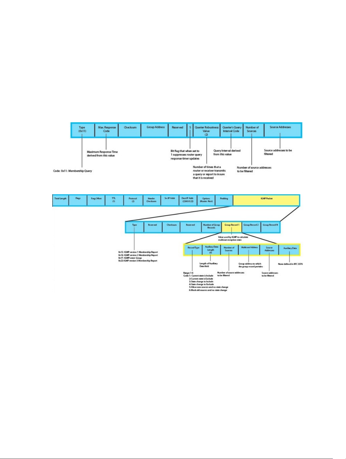
• To enable filtering, routers must keep track of more state information, that is, the list of sources that
must be filtered. An additional query type, the group-and-source-specific query, keeps track of state
changes, while the group-specific and general queries still refresh existing state.
• Reporting is more efficient and robust. Hosts do not suppress query responses (non-suppression
helps track state and enables the immediate-leave and IGMP snooping features), state-change reports
are retransmitted to insure delivery, and a single membership report bundles multiple statements from
a single host, rather than sending an individual packet for each statement.
To accommodate these protocol enhancements, the IGMP version 3 packet structure is different from
version 2. Queries (shown below in query packet format) are still sent to the all-systems address
224.0.0.1, but reports (shown below in report packet format) are sent to all the IGMP version 3 — capable
multicast routers address 224.0.0.22.
Figure 11. IGMP version 3 Membership Query Packet Format
Figure 12. IGMP version 3 Membership Report Packet Format
Joining and Filtering Groups and Sources
The below illustration shows how multicast routers maintain the group and source information from
unsolicited reports.
• The first unsolicited report from the host indicates that it wants to receive traffic for group 224.1.1.1.
• The host’s second report indicates that it is only interested in traffic from group 224.1.1.1, source
10.11.1.1. Include messages prevent traffic from all other sources in the group from reaching the
subnet, so before recording this request, the querier sends a group-and-source query to verify that
there are no hosts interested in any other sources. The multicast router must satisfy all hosts if they
have conflicting requests. For example, if another host on the subnet is interested in traffic from
10.11.1.3, the router cannot record the include request. There are no other interested hosts, so the
request is recorded. At this point, the multicast routing protocol prunes the tree to all but the
specified sources.
Internet Group Management Protocol (IGMP)
87
Page 88

• The host’s third message indicates that it is only interested in traffic from sources 10.11.1.1 and
10.11.1.2. Because this request again prevents all other sources from reaching the subnet, the router
sends another group-and-source query so that it can satisfy all other hosts. There are no other
interested hosts, so the request is recorded.
Figure 13. IGMP Membership Reports: Joining and Filtering
Leaving and Staying in Groups
The below illustration shows how multicast routers track and refreshes the state change in response to
group-and-specific and general queries.
• Host 1 sends a message indicating it is leaving group 224.1.1.1 and that the included filter for 10.11.1.1
and 10.11.1.2 are no longer necessary.
• The querier, before making any state changes, sends a group-and-source query to see if any other
host is interested in these two sources; queries for state-changes are retransmitted multiple times. If
any are interested, they respond with their current state information and the querier refreshes the
relevant state information.
• Separately in the below figure, the querier sends a general query to 224.0.0.1.
• Host 2 responds to the periodic general query so the querier refreshes the state information for that
group.
88
Internet Group Management Protocol (IGMP)
Page 89

Figure 14. IGMP Membership Queries: Leaving and Staying in Groups
IGMP Snooping
IGMP snooping is auto-configured on an Aggregator.
Multicast packets are addressed with multicast MAC addresses, which represents a group of devices
rather than one unique device. Switches forward multicast frames out of all ports in a VLAN by default,
even if there are only a small number of interested hosts, resulting in a waste of bandwidth. IGMP
snooping enables switches to use information in IGMP packets to generate a forwarding table that
associate ports with multicast groups, so that the received multicast frames are forwarded only to
interested receivers.
How IGMP Snooping is Implemented on an Aggregator
• IGMP snooping is enabled by default on the switch.
• Dell Networking OS supports version 1, version 2 and version 3 hosts.
• Dell Networking OS — IGMP snooping is based on the IP multicast address (not on the Layer 2
multicast MAC address). IGMP snooping entries are stored in the Layer 3 flow table instead of in the
Layer 2 forwarding information base (FIB).
• Dell Networking OS — IGMP snooping is based on draft-ietf-magma-snoop-10.
• IGMP snooping is supported on all M I/O Aggregator stack members.
• A maximum of 2k groups and 4k virtual local area networks (VLAN) are supported.
• IGMP snooping is not supported on the default VLAN interface.
• Flooding of unregistered multicast traffic is enabled by default.
• Queries are not accepted from the server side ports and are only accepted from the uplink LAG.
• Reports and Leaves are flooded by default to the uplink LAG irrespective of whether it is an mrouter
port or not.
Internet Group Management Protocol (IGMP)
89
Page 90

Disabling Multicast Flooding
If the switch receives a multicast packet that has an IP address of a group it has not learned (unregistered
frame), the switch floods that packet out of all ports on the VLAN. To disable multicast flooding on all
VLAN ports, enter the
When multicast flooding is disabled, unregistered multicast data traffic is forwarded to only multicast
router ports on all VLANs. If there is no multicast router port in a VLAN, unregistered multicast data traffic
is dropped.
no ip igmp snooping flood command in global configuration mode.
Displaying IGMP Information
Use the show commands from the below table, to display information on IGMP. If you specify a group
address or interface:
• Enter a group address in dotted decimal format; for example, 225.0.0.0.
• Enter an interface in one of the following formats: tengigabitethernet slot/port, port-
channel port-channel-number, or vlan vlan-number.
Displaying IGMP Information
Command Output
show ip igmp groups [group-address [detail]
| detail | interface [group-address [detail]]
show ip igmp interface [interface] Displays IGMP information on IGMP-enabled interfaces.
show ip igmp snooping mrouter [vlan vlan-
number]
clear ip igmp groups [group-address |
interface]
show ip igmp groups Command Example
Dell# show ip igmp groups
Total Number of Groups: 2
IGMP Connected Group Membership
Group Address Interface Mode Uptime Expires
Last Reporter
226.0.0.1 Vlan 1500 INCLUDE 00:00:19 Never
1.1.1.2
226.0.0.1 Vlan 1600 INCLUDE 00:00:02 Never
1.1.1.2
Dell#show ip igmp groups detail
Interface Vlan 1500
Group 226.0.0.1
Uptime 00:00:21
Expires Never
Router mode INCLUDE
Last reporter 1.1.1.2
Last reporter mode INCLUDE
Last report received IS_INCL
Group source list
Displays information on IGMP groups.
Displays information on IGMP-enabled multicast router
(mrouter) interfaces.
Clears IGMP information for group addresses and IGMPenabled interfaces.
90
Internet Group Management Protocol (IGMP)
Page 91

Source address Uptime Expires
1.1.1.2 00:00:21 00:01:48
Member Ports: Po 1
Interface Vlan 1600
Group 226.0.0.1
Uptime 00:00:04
Expires Never
Router mode INCLUDE
Last reporter 1.1.1.2
Last reporter mode INCLUDE
Last report received IS_INCL
Group source list
Source address Uptime Expires
1.1.1.2 00:00:04 00:02:05
Member Ports: Po 1
Dell#
show ip igmp interface Command Example
Dell# show ip igmp interface
Vlan 2 is up, line protocol is down
Inbound IGMP access group is not set
Interface IGMP group join rate limit is not set
IGMP snooping is enabled on interface
IGMP Snooping query interval is 60 seconds
IGMP Snooping querier timeout is 125 seconds
IGMP Snooping last member query response interval is 1000 ms
IGMP snooping fast-leave is disabled on this interface
IGMP snooping querier is disabled on this interface
Vlan 3 is up, line protocol is down
Inbound IGMP access group is not set
Interface IGMP group join rate limit is not set
IGMP snooping is enabled on interface
IGMP Snooping query interval is 60 seconds
IGMP Snooping querier timeout is 125 seconds
IGMP Snooping last member query response interval is 1000 ms
IGMP snooping fast-leave is disabled on this interface
IGMP snooping querier is disabled on this interface
--More--
show ip igmp snooping mrouter Command Example
Dell# show ip igmp snooping mrouter
Interface Router Ports
Vlan 1000 Po 128
Dell#
Internet Group Management Protocol (IGMP)
91
Page 92

8
Interfaces
This chapter describes 100/1000/10000 Mbps Ethernet, 10 Gigabit Ethernet, and 40 Gigabit Ethernet
interface types, both physical and logical, and how to configure them with the Dell Networking Operating
Software (OS).
Basic Interface Configuration
• Interface Auto-Configuration
• Interface Types
• Viewing Interface Information
• Disabling and Re-enabling a Physical Interface
• Layer 2 Mode
• Management Interfaces
• VLAN Membership
• Port Channel Interfaces
Advanced Interface Configuration
• Monitor and Maintain Interfaces
• Flow Control Using Ethernet Pause Frames
• MTU Size
• Auto-Negotiation on Ethernet Interfaces
• Viewing Interface Information
Interface Auto-Configuration
An Aggregator auto-configures interfaces as follows:
• All interfaces operate as layer 2 interfaces at 10GbE in standalone mode. FlexIO module interfaces
support only uplink connections. You can only use the 40GbE ports on the base module for stacking.
– By default, the two fixed 40GbE ports on the base module operate in 4x10GbE mode with
breakout cables and support up to eight 10GbE uplinks. You can configure the base-module ports
as 40GbE links for stacking.
– The interfaces on a 40GbE QSFP+ FlexIO module auto-configure to support only 10GbE SFP
+connections using 4x10GbE breakout cables.
• All 10GbE uplink interfaces belong to the same 10GbE link aggregation group (LAG).
92
Interfaces
Page 93

– The tagged Virtual Local Area Network (VLAN) membership of the uplink LAG is automatically
configured based on the VLAN configuration of all server-facing ports (ports 1 to 32). The
untagged VLAN used for the uplink LAG is always the default VLAN 1.
– The tagged VLAN membership of a server-facing LAG is automatically configured based on the
server-facing ports that are members of the LAG. The untagged VLAN of a server-facing LAG is
auto-configured based on the untagged VLAN to which the lowest numbered server-facing port in
the LAG belongs.
• All interfaces are auto-configured as members of all (4094) VLANs and untagged VLAN 1. All VLANs
are up and can send or receive layer 2 traffic. You can use the Command Line Interface (CLI) or CMC
interface to configure only the required VLANs on a port interface.
• Aggregator ports are numbered 1 to 56. Ports 1 to 32 are internal server-facing interfaces. Ports 33 to
56 are external ports numbered from the bottom to the top of the Aggregator.
Interface Types
The following interface types are supported on an Aggregator.
Interface Type Supported
Modes
Physical L2 10GbE uplink No No Shutdown (enabled)
Management L3 L3 No No Shutdown (enabled)
Port Channel L2 L2 No L2 - No Shutdown (enabled)
Default Mode Requires
Creation
Default State
Default VLAN L2 and L3 L2 and L3
(VLAN 1)
Non-default VLANs
(VLANs 2 - 4094)
L2 L2 and L3 Yes L2 - No Shutdown (enabled)L3 -
No L2 - No Shutdown (enabled)L3 -
No Shutdown (enabled)
No Shutdown (enabled)
Viewing Interface Information
To view interface status and auto-configured parameters use show commands.
The show interfaces command in EXEC mode lists all configurable interfaces on the chassis and has
options to display the interface status, IP and MAC addresses, and multiple counters for the amount and
type of traffic passing through the interface. If you configure a port channel interface, the show
interfaces
NOTE: To end output from the system, such as the output from the show interfaces command,
enter CTRL+C and the Dell Networking Operating System (OS) returns to the command prompt.
NOTE: The CLI output may be incorrectly displayed as 0 (zero) for the Rx/Tx power values. Perform
an simple network management protocol (SNMP) query to obtain the correct power information.
The following example shows the configuration and status information for one interface.
Dell#show interface tengig 1/16
TenGigabitEthernet 1/16 is up, line protocol is up
Hardware is DellForce10Eth, address is 00:01:e8:00:ab:01
Current address is 00:01:e8:00:ab:01
Server Port AdminState is Up
Pluggable media not present
Interface index is 71635713
command lists the interfaces configured in the port channel.
Interfaces
93
Page 94

Internet address is not set
Mode of IP Address Assignment : NONE
DHCP Client-ID :tenG2730001e800ab01
MTU 12000 bytes, IP MTU 11982 bytes
LineSpeed 1000 Mbit
Flowcontrol rx off tx off
ARP type: ARPA, ARP Timeout 04:00:00
Last clearing of "show interface" counters 11:04:02
Queueing strategy: fifo
Input Statistics:
0 packets, 0 bytes
0 64-byte pkts, 0 over 64-byte pkts, 0 over 127-byte pkts
0 over 255-byte pkts, 0 over 511-byte pkts, 0 over 1023-byte pkts
0 Multicasts, 0 Broadcasts
0 runts, 0 giants, 0 throttles
0 CRC, 0 overrun, 0 discarded
Output Statistics:
14856 packets, 2349010 bytes, 0 underruns
0 64-byte pkts, 4357 over 64-byte pkts, 8323 over 127-byte pkts
2176 over 255-byte pkts, 0 over 511-byte pkts, 0 over 1023-byte pkts
12551 Multicasts, 2305 Broadcasts, 0 Unicasts
0 throttles, 0 discarded, 0 collisions, 0 wreddrops
Rate info (interval 299 seconds):
Input 00.00 Mbits/sec, 0 packets/sec, 0.00% of line-rate
Output 00.00 Mbits/sec, 0 packets/sec, 0.00% of line-rate
Time since last interface status change: 11:01:23
To view only configured interfaces use the show interfaces configured command in EXEC Privilege
mode.
To determine which physical interfaces are available, use the show running-config command in
EXEC mode. This command displays all physical interfaces available on the switch, which is as shown in
the following example.
Dell#show running config
Current Configuration ...
! Version E8-3-17-38
! Last configuration change at Tue Jul 24 20:48:55 2012 by default
!
boot system stack-unit 1 primary tftp://10.11.9.21/dv-m1000e-2-b2
boot system stack-unit 1 default system: A:
boot system gateway 10.11.209.62
!
redundancy auto-synchronize full
!
service timestamps log datetime
!
hostname FTOS
!
username root password 7 d7acc8a1dcd4f698 privilege 15
mac-address-table aging-time 300
!
stack-unit 1 provision I/O-Aggregator
!
stack-unit 1 port 33 portmode quad
!
stack-unit 1 port 37 portmode quad
--More--
94
Interfaces
Page 95

Disabling and Re-enabling a Physical Interface
By default, all port interfaces on an Aggregator are operationally enabled (no shutdown) to send and
receive Layer 2 traffic. You can reconfigure a physical interface to shut it down by entering the shutdown
command. To re-enable the interface, enter the no shutdown command.
Step Command Syntax Command Mode Purpose
1.
2.
To confirm that the interface is enabled, use the show config command in INTERFACE mode.
To leave INTERFACE mode, use the exit command or end command.
You cannot delete a physical interface.
The management IP address on the D-fabric provides a dedicated management access to the system.
The switch interfaces support Layer 2 traffic over the 10-Gigabit Ethernet interfaces. These interfaces can
also become part of virtual interfaces such as VLANs or port channels.
For more information about VLANs, refer to VLANs and Port Tagging. For more information about port
channels, refer to Port Channel Interfaces.
interface interface CONFIGURATION Enter the keyword interface followed by the type of
interface and slot/port information:
• For a 10GbE interface, enter the keyword
TenGigabitEthernet followed by the slot/port
numbers; for example, interface
tengigabitethernet 0/5.
• For the management interface on a stack-unit,
enter the keyword ManagementEthernet followed
by the slot/port numbers; for example, interface
managementethernet 0/0.
shutdown INTERFACE Enter the shutdown command to disable the interface.
Dell Networking OS Behavior: The Aggregator uses a single MAC address for all physical interfaces.
Layer 2 Mode
On an Aggregator, physical interfaces, port channels, and VLANs auto-configure to operate in Layer 2
mode. Following example demonstrates about the basic configurations found in Layer 2 interface.
NOTE: Layer 3 (Network) mode is not supported on Aggregator physical interfaces, port channels
and VLANs. Only management interfaces operate in Layer 3 mode.
Dell(conf-if-te-0/1)#show config
!
interface TenGigabitEthernet 0/1
mtu 12000
portmode hybrid
switchport
auto vlan
!
protocol lldp
Interfaces
95
Page 96

advertise management-tlv system-name
dcbx port-role auto-downstream
no shutdown
Dell(conf-if-te-0/1)#
To view the interfaces in Layer 2 mode, use the show interfaces switchport command in EXEC
mode.
Management Interfaces
An Aggregator auto-configures with a DHCP-based IP address for in-band management on VLAN 1 and
remote out-of-band (OOB) management.
The IOM management interface has both a public IP and private IP address on the internal Fabric D
interface. The public IP address is exposed to the outside world for WebGUI configurations/WSMAN and
other proprietary traffic. You can statically configure the public IP address or obtain the IP address
dynamically using the dynamic host configuration protocol (DHCP).
Accessing an Aggregator
You can access the Aggregator using:
• Internal RS-232 using the chassis management controller (CMC). Telnet into CMC and do a connect
—b switch-id to get console access to corresponding IOM.
• External serial port with a universal serial bus (USB) connector (front panel): connect using the IOM
front panel USB serial line to get console access (Labeled as USB B).
• Telnet/ssh using the public IP interface on the fabric D interface.
• CMC through the private IP interface on the fabric D interface.
The Aggregator supports the management ethernet interface as well as the standard interface on any
front-end port. You can use either method to connect to the system.
Configuring a Management Interface
On the Aggregator, the dedicated management interface provides management access to the
system.You can configure this interface with Dell Networking OS, but the configuration options on this
interface are limited. You cannot configure gateway addresses and IP addresses if it appears in the main
routing table of Dell Networking OS. In addition, the proxy address resolution protocol (ARP) is not
supported on this interface.
For additional management access, IOM supports the default VLAN (VLAN 1) L3 interface in addition to
the public fabric D management interface. You can assign the IP address for the VLAN 1 default
management interface using the setup wizard or through the CLI.
If you do not configure the default VLAN 1 in the startup configuration using the wizard or CLI, by default,
the VLAN 1 management interface gets its IP address using DHCP.
To configure a management interface, use the following command in CONFIGURATION mode:
Command Syntax Command Mode Purpose
interface Managementethernet interface CONFIGURATION Enter the slot and the port (0).
96
Interfaces
Page 97

Slot range: 0-0
To configure an IP address on a management interface, use either of the following commands in
MANAGEMENT INTERFACE mode:
Command Syntax Command Mode Purpose
ip address ip-address mask INTERFACE Configure an IP address and mask on
the interface.
• ip-address mask: enter an address in
dotted-decimal format (A.B.C.D),
the mask must be in /prefix format
(/x)
ip address dhcp INTERFACE Acquire an IP address from the DHCP
server.
To access the management interface from another LAN, you must configure the management route
command to point to the management interface.
There is only one management interface for the whole stack.
To display the routing table for a given port, use the show ip route command from EXEC Privilege
mode.
Configuring a Static Route for a Management Interface
When an IP address used by a protocol and a static management route exists for the sample prefix, the
protocol route takes precedence over the static management route.
To configure a static route for the management port, use the following command in CONFIGURATION
mode:
Command Syntax Command Mode Purpose
management route ip-address
mask {forwarding-router-address |
ManagementEthernet slot/port}
To view the configured static routes for the management port, use the show ip management-route
command in EXEC privilege mode.
Dell#show ip management-route all
Destination Gateway State
----------- ------- -----
1.1.1.0/24 172.31.1.250 Active
172.16.1.0/24 172.31.1.250 Active
172.31.1.0/24 ManagementEthernet 1/0 Connected
Dell#
CONFIGURATION Assign a static route to point to the
management interface or forwarding router.
Interfaces
97
Page 98

VLAN Membership
A virtual LAN (VLANs) is a logical broadcast domain or logical grouping of interfaces in a LAN in which all
data received is kept locally and broadcast to all members of the group. In Layer 2 mode, VLANs move
traffic at wire speed and can span multiple devices. Dell Networking OS supports up to 4093 port-based
VLANs and one default VLAN, as specified in IEEE 802.1Q.
VLAN provide the following benefits:
• Improved security because you can isolate groups of users into different VLANs.
• Ability to create one VLAN across multiple devices.
On an Aggregator in standalone mode, all ports are configured by default as members of all (4094)
VLANs, including the default VLAN. All VLANs operate in Layer 2 mode. You can reconfigure the VLAN
membership for individual ports by using the vlan tagged or vlan untagged commands in
INTERFACE configuration mode (Configuring VLAN Membership). Physical Interfaces and port channels
can be members of VLANs.
NOTE: You can assign a static IP address to default VLAN 1 using the ip address command. To
assign a different VLAN ID to the default VLAN, use the default vlan-id vlan-id command.
Following table lists out the VLAN defaults in Dell Networking OS:
Feature Default
Mode Layer 2 (no IP address is assigned)
Default VLAN ID VLAN 1
Default VLAN
When an Aggregator boots up, all interfaces are up in Layer 2 mode and placed in the default VLAN as
untagged interfaces. Only untagged interfaces can belong to the default VLAN.
By default, VLAN 1 is the default VLAN. To change the default VLAN ID, use the default vlan-id <1–
4094> command in CONFIGURATION mode. You cannot delete the default VLAN.
Port-Based VLANs
Port-based VLANs are a broadcast domain defined by different ports or interfaces. In Dell Networking OS,
a port-based VLAN can contain interfaces from different stack units within the chassis. Dell Networking
OS supports 4094 port-based VLANs.
Port-based VLANs offer increased security for traffic, conserve bandwidth, and allow switch
segmentation. Interfaces in different VLANs do not communicate with each other, adding some security
to the traffic on those interfaces. Different VLANs can communicate between each other by means of IP
routing. Because traffic is only broadcast or flooded to the interfaces within a VLAN, the VLAN conserves
bandwidth. Finally, you can have multiple VLANs configured on one switch, thus segmenting the device
Interfaces within a port-based VLAN must be in Layer 2 mode and can be tagged or untagged in the
VLAN ID.
98
Interfaces
Page 99
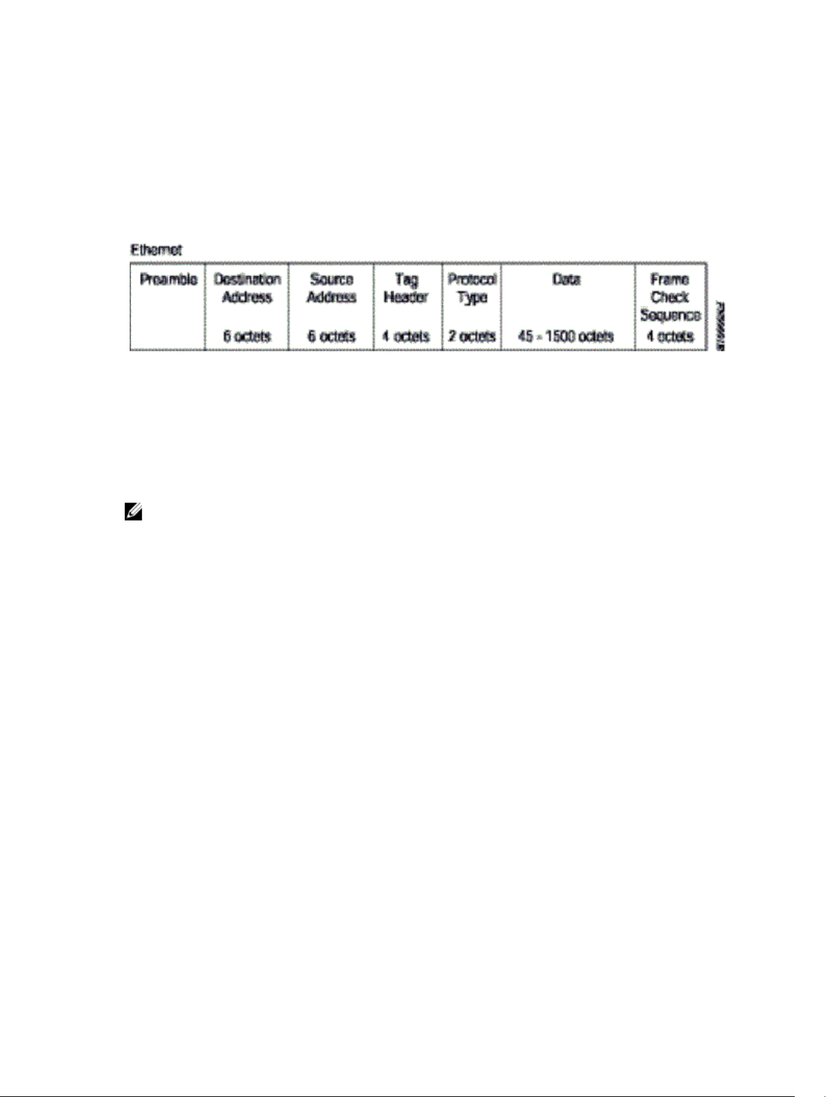
VLANs and Port Tagging
To add an interface to a VLAN, it must be in Layer 2 mode. After you place an interface in Layer 2 mode, it
is automatically placed in the default VLAN. Dell Networking OS supports IEEE 802.1Q tagging at the
interface level to filter traffic. When you enable tagging, a tag header is added to the frame after the
destination and source MAC addresses. The information that is preserved as the frame moves through the
network. The below figure shows the structure of a frame with a tag header. The VLAN ID is inserted in
the tag header.
Figure 15. Tagged Frame Format
The tag header contains some key information used by Dell Networking OS:
• The VLAN protocol identifier identifies the frame as tagged according to the IEEE 802.1Q
specifications (2 bytes).
• Tag control information (TCI) includes the VLAN ID (2 bytes total). The VLAN ID can have 4,096 values,
but two are reserved.
NOTE: The insertion of the tag header into the Ethernet frame increases the size of the frame to
more than the 1518 bytes specified in the IEEE 802.3 standard. Some devices that are not compliant
with IEEE 802.3 may not support the larger frame size.
Information contained in the tag header allows the system to prioritize traffic and to forward information
to ports associated with a specific VLAN ID. Tagged interfaces can belong to multiple VLANs, while
untagged interfaces can belong only to one VLAN.
Configuring VLAN Membership
By default, all Aggregator ports are member of all (4094) VLANs, including the default untagged VLAN 1.
You can use the CLI or CMC interface to reconfigure VLANs only on server-facing interfaces (1–8) so that
an interface has membership only in specified VLANs.
To assign an Aggregator interface in Layer 2 mode to a specified group of VLANs, use the vlan tagged
and vlan untagged commands. To view which interfaces are tagged or untagged and to which VLAN
they belong, use the show vlan command (Displaying VLAN Membership).
To reconfigure an interface as a member of only specified tagged VLANs, enter the vlan tagged
command in INTERFACE mode:
Command Syntax Command Mode Purpose
vlan tagged {vlan-id } INTERFACE Add the interface as a tagged member of one or
more VLANs, where:
Interfaces
99
Page 100

vlan-id specifies a tagged VLAN number. Range:
2-4094
To reconfigure an interface as a member of only specified untagged VLANs, enter the vlan untagged
command in INTERFACE mode:
Command Syntax Command Mode Purpose
vlan untagged {vlan-id} INTERFACE Add the interface as an untagged member of
one or more VLANs, where:
vlan-id specifies an untagged VLAN number.
Range: 2-4094
If you configure additional VLAN membership and save it to the startup configuration, the new VLAN
configuration takes place immediately.
Dell Networking OS Behavior: When two or more server-facing ports with VLAN membership are
configured in a LAG based on the NIC teaming configuration in connected servers learned via LACP, the
resulting LAG is a tagged member of all the configured VLANs and an untagged member of the VLAN to
which the port with the lowest port ID belongs. For example, if port 0/3 is an untagged member of VLAN
2 and port 0/4 is an untagged member of VLAN 3, the resulting LAG consisting of the two ports is an
untagged member of VLAN 2 and a tagged member of VLAN 3.
Displaying VLAN Membership
To view the configured VLANs, enter the show vlan command in EXEC privilege mode:
Dell#show vlan
Codes: * - Default VLAN, G - GVRP VLANs, R - Remote Port Mirroring VLANs, P Primary, C Community, I - Isolated
Q: U - Untagged, T - Tagged
x - Dot1x untagged, X - Dot1x tagged
G - GVRP tagged, M - Vlan-stack, H - VSN tagged
i - Internal untagged, I - Internal tagged, v - VLT untagged, V - VLT tagged
NUM Status Description Q Ports
1 Inactive
* 20 Active U Po32()
U Te 0/3,5,13,53-56
1002 Active T Te 0/3,13,55-56
Dell#
NOTE: A VLAN is active only if the VLAN contains interfaces and those interfaces are operationally
up. In the above example, VLAN 1 is inactive because it does not contain any interfaces. The other
VLANs listed contain enabled interfaces and are active. In a VLAN, the shutdown command stops
Layer 3 (routed) traffic only. Layer 2 traffic continues to pass through the VLAN. If the VLAN is not a
routed VLAN (that is, configured with an IP address), the shutdown command has no affect on VLAN
traffic.
100
Interfaces
 Loading...