

Dell PowerEdge M820 Systems Owner's Manual

Dell PowerEdge M820 Systems
Owner's Manual
Regulatory Model: FHB
Regulatory Type: FHB007

Notes, Cautions, and Warnings
NOTE: A NOTE indicates important information that helps you make better use of your computer.
CAUTION: A CAUTION indicates either potential damage to hardware or loss of data and tells you how to avoid the
problem.
WARNING: A WARNING indicates a potential for property damage, personal injury, or death.
© 2013 Dell Inc. All Rights Reserved.
Trademarks used in this text:
Dell
™
, the Dell logo,
Dell Boomi
™
,
Dell Precision
™
,
OptiPlex
™
,
Latitude
™
,
PowerEdge
™
,
PowerVault
™
,
PowerConnect
™
,
OpenManage
™
,
EqualLogic
™
,
Compellent
™
,
KACE
™
,
FlexAddress
™
,
Force10
™
,
Venue
™
and
Vostro
™
are trademarks
of Dell Inc.
Intel
®
,
Pentium
®
,
Xeon
®
,
Core
®
and
Celeron
®
are registered trademarks of Intel Corporation in the U.S. and other countries.
AMD
®
is a registered trademark and
AMD Opteron
™
,
AMD Phenom
™
and
AMD Sempron
™
are trademarks of Advanced Micro
Devices, Inc.
Microsoft
®
,
Windows
®
,
Windows Server
®
,
Internet Explorer
®
,
MS-DOS
®
,
Windows Vista
®
and
Active Directory
®
are
either trademarks or registered trademarks of Microsoft Corporation in the United States and/or other countries.
Red Hat
®
and
Red Hat
®
Enterprise Linux
®
are registered trademarks of Red Hat, Inc. in the United States and/or other countries.
Novell
®
and
SUSE
®
are registered trademarks of Novell Inc. in the United States and other countries.
Oracle
®
is a registered trademark of Oracle
Corporation and/or its affiliates.
Citrix
®
,
Xen
®
,
XenServer
®
and
XenMotion
®
are either registered trademarks or trademarks of Citrix
Systems, Inc. in the United States and/or other countries.
VMware
®
,
vMotion
®
,
vCenter
®
,
vCenter SRM
™
and
vSphere
®
are registered
trademarks or trademarks of VMware, Inc. in the United States or other countries.
IBM
®
is a registered trademark of International
Business Machines Corporation.
2013 - 09
Rev. A02

Contents
1 About Your System......................................................................................................................7
Front-Panel Features And Indicators....................................................................................................................... 7
Using USB Diskette or USB DVD/CD Drives............................................................................................................. 7
Hard-Drive/SSD Indicator Patterns.......................................................................................................................... 7
Other Information You May Need.............................................................................................................................8
2 Using The System Setup And Boot Manager.......................................................................11
Choosing The System Boot Mode.......................................................................................................................... 11
Entering System Setup............................................................................................................................................12
Responding To Error Messages.......................................................................................................................12
Using The System Setup Navigation Keys....................................................................................................... 12
System Setup Options.............................................................................................................................................13
System Setup Main Screen..............................................................................................................................13
System BIOS Screen........................................................................................................................................13
System Information Screen..............................................................................................................................14
Memory Settings Screen................................................................................................................................. 14
Processor Settings Screen.............................................................................................................................. 15
Boot Settings Screen....................................................................................................................................... 16
Integrated Devices Screen.............................................................................................................................. 16
Serial Communications Screen........................................................................................................................17
System Profile Settings Screen........................................................................................................................18
System Security Screen...................................................................................................................................18
Miscellaneous Settings....................................................................................................................................19
System And Setup Password Features.................................................................................................................. 20
Assigning A System And/Or Setup Password..................................................................................................20
Using Your System Password To Secure Your System....................................................................................21
Deleting Or Changing An Existing System And/Or Setup Password................................................................21
Operating With A Setup Password Enabled.................................................................................................... 22
Entering The UEFI Boot Manager........................................................................................................................... 22
Using The Boot Manager Navigation Keys......................................................................................................22
Boot Manager Screen......................................................................................................................................23
UEFI Boot Menu............................................................................................................................................... 23
Embedded System Management............................................................................................................................23
iDRAC Settings Utility..............................................................................................................................................24
Entering The iDRAC Settings Utility..................................................................................................................24
3 Installing Blade Components.................................................................................................. 25
Recommended Tools.............................................................................................................................................. 25

Removing And Installing A Blade........................................................................................................................... 25
Removing The Blade........................................................................................................................................ 25
Installing A Full-Height Blade...........................................................................................................................26
Opening And Closing The Blade............................................................................................................................. 26
Opening The Blade...........................................................................................................................................26
Closing The Blade............................................................................................................................................ 27
Inside The Blade.....................................................................................................................................................28
Cooling Shroud....................................................................................................................................................... 29
Removing The Cooling Shroud......................................................................................................................... 29
Installing The Cooling Shroud.......................................................................................................................... 30
Hard Drives/SSDs................................................................................................................................................... 30
Removing A Hard Drive/PCIe SSD................................................................................................................... 31
Installing A Hard Drive/PCIe SSD.....................................................................................................................32
Shutdown Procedure For Servicing A Hard Drive/PCIe SSD...........................................................................32
Configuring The Boot Drive.............................................................................................................................. 32
Removing A Hard Drive/PCIe SSD From A Hard-Drive/PCIe SSD Carrier........................................................32
Installing A Hard Drive/PCIe SSD In A Hard-Drive/PCIe SSD Carrier..............................................................33
Hard Drive/SSD Backplane.....................................................................................................................................33
Removing The Hard-Drive/SSD Backplane......................................................................................................34
Installing The Hard-Drive/SSD Backplane.......................................................................................................36
I/O Module Mezzanine Cards................................................................................................................................. 37
Mezzanine Card Installation Guidelines...........................................................................................................37
Removing A Mezzanine Card........................................................................................................................... 37
Installing A Mezzanine Card.............................................................................................................................38
Network Daughter Card/LOM Riser Card............................................................................................................... 39
Removing The Network Daughter Card/LOM Riser Card.................................................................................39
Installing The Network Daughter Card/LOM Riser Card..................................................................................40
Management Riser Card.........................................................................................................................................40
Replacing The SD Card.................................................................................................................................... 40
Internal USB Key.............................................................................................................................................. 41
SD vFlash Card........................................................................................................................................................42
Replacing The SD vFlash Card......................................................................................................................... 42
Processor/DIMM Blank..........................................................................................................................................43
Removing A Processor/DIMM Blank............................................................................................................... 43
Installing A Processor/DIMM Blank................................................................................................................ 44
Processors..............................................................................................................................................................45
Removing A Processor.....................................................................................................................................45
Installing A Processor......................................................................................................................................49
System Board..........................................................................................................................................................50
Removing The System Board........................................................................................................................... 50
Installing The System Board............................................................................................................................ 51
System Memory......................................................................................................................................................52

General Memory Module Installation Guidelines............................................................................................ 54
Mode-Specific Guidelines................................................................................................................................55
Sample Memory Configurations.......................................................................................................................56
Removing Memory Modules............................................................................................................................ 59
Installing Memory Modules............................................................................................................................. 60
NVRAM Backup Battery......................................................................................................................................... 62
Replacing The NVRAM Backup Battery.......................................................................................................... 62
Storage Controller Card/PCIe Extender Card......................................................................................................... 63
Removing The Storage Controller Card/PCIe Extender Card...........................................................................63
Installing The Storage Controller Card/PCIe Extender Card............................................................................ 65
4 Troubleshooting Your System................................................................................................. 67
Safety First—For You and Your System..................................................................................................................67
Troubleshooting System Memory...........................................................................................................................67
Troubleshooting Hard Drives..................................................................................................................................68
Troubleshooting USB Devices................................................................................................................................68
Troubleshooting An Internal SD Card.....................................................................................................................69
Troubleshooting Processors...................................................................................................................................69
Troubleshooting The Blade System Board.............................................................................................................69
Troubleshooting The NVRAM Backup Battery.......................................................................................................70
5 Using System Diagnostics....................................................................................................... 71
Dell Online Diagnostics...........................................................................................................................................71
Dell Embedded System Diagnostics....................................................................................................................... 71
When To Use The Embedded System Diagnostics.......................................................................................... 71
Running The Embedded System Diagnostics...................................................................................................71
System Diagnostic Controls............................................................................................................................. 72
6 Jumpers And Connectors........................................................................................................ 73
System Board Jumper Settings.............................................................................................................................. 73
System Board Connectors......................................................................................................................................74
Disabling A Forgotten Password............................................................................................................................ 75
7 Technical Specifications......................................................................................................... 77
8 System Messages.....................................................................................................................81
LCD Status Messages.............................................................................................................................................81
Viewing LCD Messages................................................................................................................................... 81
Removing LCD Messages.................................................................................................................................81
System Error Messages..........................................................................................................................................81
Warning Messages...............................................................................................................................................150
Diagnostic Messages........................................................................................................................................... 150

Alert Messages.....................................................................................................................................................150
9 Getting Help..............................................................................................................................151
Contacting Dell..................................................................................................................................................... 151
1
About Your System
Front-Panel Features And Indicators
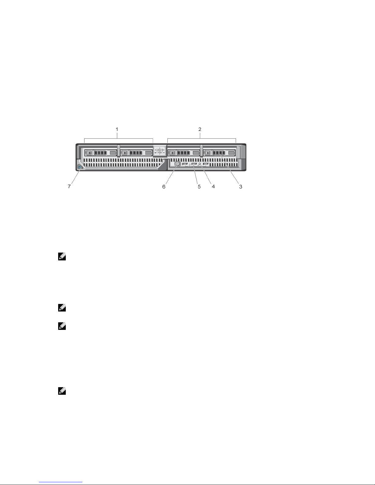
Figure 1. Front-Panel Features and Indicators
1. drive bay 0
2. drive bay 1
3. SAS hard drives/PCIe SSDs
4. status/identification indicator
5. USB connectors (3)
6. blade power button
7. blade handle release button
NOTE: For more information on supported hard-drive/PCIe SSD configurations, see Hard Drives/SSDs.
Using USB Diskette or USB DVD/CD Drives
The blade has USB ports on the front which allow you to connect a USB diskette drive, USB flash drive, USB DVD/CD
drive, keyboard, or mouse. The USB drives can be used to configure the blade.
NOTE: Your blade supports only Dell-branded USB 2.0 drives. Use the optional external drive storage tray to
support the drive while in use.
NOTE: If the drive must be designated as the boot drive, connect the USB drive, restart the system, then enter the
System Setup and set the drive as first in the boot sequence. The USB device is displayed in the boot order setup
screen only if it is attached to the system before you run the System Setup. You can also select the boot device by
pressing <F11> during system start-up and selecting a boot device for the current boot sequence.
Hard-Drive/SSD Indicator Patterns
The hard-drive/SSD indicators display different patterns as drive events occur in the system.
NOTE: The blade must have a hard drive/SSD or a hard-drive blank installed in each drive bay.
7
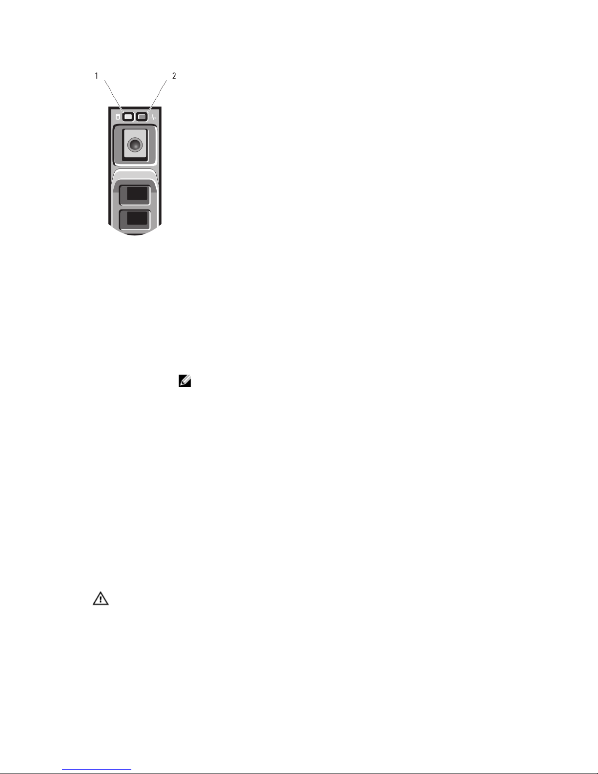
Figure 2. Hard-Drive/SSD Indicators
1. drive activity indicator (green)
2. drive status indicator (green and amber)
Drive-Status
Indicator Pattern
Condition
Blinks green two
times per second
Identifying drive or preparing for removal
Off Drive ready for insertion or removal
NOTE: The drive status indicator remains off until all hard drives are initialized after system
power is applied. Drives are not ready for insertion or removal during this time.
Blinks green, amber,
and off
Drive predicted failure
Blinks amber four
times per second
Drive failed
Blinks green slowly Drive rebuilding
Steady green Drive online
Blinks green three
seconds, amber three
seconds, and off six
seconds
Rebuild aborted
Other Information You May Need
WARNING: See the safety and regulatory information that shipped with your system. Warranty information may be
included within this document or as a separate document.
• The
Getting Started Guide
provides an overview of system features, setting up your system, and technical
specifications.
• The
Rack Installation Instructions
included with your rack solution describes how to install your system into a
rack.
8

• The
Dell PowerEdge M1000e Enclosure Owner’s Manual
provides information about enclosure features and
describes how to troubleshoot the enclosure and install or replace the enclosure's components.
• The
Dell Chassis Management Controller User’s Guide
provides information on installing, configuring and using
the Chassis Management Controller (CMC).
• For the full name of an abbreviation or acronym used in this document, see the Glossary at www.dell.com/
support/manuals.
• Dell systems management application documentation provides information about installing and using the
systems management software.
• Any media that ships with your system that provides documentation and tools for configuring and managing your
system, including those pertaining to the operating system, system management software, system updates, and
system components that you purchased with your system.
NOTE: Always check for updates on www.dell.com/support/manuals and read the updates first because they often
supersede information in other documents.
9

10

2
Using The System Setup And Boot Manager
System Setup enables you to manage your system hardware and specify BIOS-level options.
The following keystrokes provide access to system features during startup:
Keystroke
Description
<F2>
Enters the System Setup.
<F10>
Enters System Services, which opens the Dell Lifecycle
Controller 2 (LC2). The Dell LC2 supports systems
management features such as operating system
deployment, hardware diagnostics, platform updates, and
platform configuration, using a graphical user interface.
The exact LC2 feature set is determined by the iDRAC
license purchased. For more information, see the Dell LC2
documentation.
<F11>
Enters the BIOS Boot Manager or the Unified Extensible
Firmware Interface (UEFI) Boot Manager, depending on
the system's boot configuration
.
<F12>
Starts Preboot Execution Environment (PXE) boot.
From the System Setup, you can:
• Change the NVRAM settings after you add or remove hardware
• View the system hardware configuration
• Enable or disable integrated devices
• Set performance and power management thresholds
• Manage system security
You can access the System Setup using the:
• Standard graphical browser, which is enabled by default
• Text browser, which is enabled using Console Redirection
To enable Console Redirection, in System Setup, select System BIOS → Serial Communication screen → Serial
Communication, select On with Console Redirection.
NOTE: By default, help text for the selected field is displayed in the graphical browser. To view the help text in the
text browser, press <F1>.
Choosing The System Boot Mode
System Setup enables you to specify the boot mode for installing your operating system:
• BIOS boot mode (the default) is the standard BIOS-level boot interface.
11

• UEFI boot mode is an enhanced 64-bit boot interface based on Unified Extensible Firmware Interface (UEFI)
specifications that overlays the system BIOS.
You must select the boot mode in the Boot Mode field of the Boot Settings screen of System Setup. Once you specify the
boot mode, the system boots in the specified boot mode and you then proceed to install your operating system from that
mode. Thereafter, you must boot the system in the same boot mode (BIOS or UEFI) to access the installed operating
system. Trying to boot the operating system from the other boot mode will cause the system to halt at startup.
NOTE: Operating systems must be UEFI-compatible to be installed from the UEFI boot mode. DOS and 32-bit
operating systems do not support UEFI and can only be installed from the BIOS boot mode.
NOTE: For the latest information on supported operating systems, go to dell.com/ossupport.
Entering System Setup
1. Turn on or restart your system.
2. Press <F2> immediately after you see the following message:
<F2> = System Setup
If your operating system begins to load before you press <F2>, allow the system to finish booting, and then restart
your system and try again.
Responding To Error Messages
If an error message is displayed while the system is booting, make a note of the message. For more information, see
System Error Messages.
NOTE: After installing a memory upgrade, it is normal for your system to display a message the first time you start
your system.
Using The System Setup Navigation Keys
Keys Action
Up arrow Moves to the previous field.
Down arrow Moves to the next field.
<Enter> Allows you to type in a value in the selected field (if applicable) or follow the link in the field.
Spacebar Expands or collapses a drop-down menu, if applicable.
<Tab> Moves to the next focus area.
NOTE: For the standard graphics browser only.
<Esc> Moves to the previous page till you view the main screen. Pressing <Esc> in the main screen
displays a message that prompts you to save any unsaved changes and restarts the system.
<F1> Displays the System Setup help file.
NOTE: For most of the options, any changes that you make are recorded but do not take
effect until you restart the system.
12

System Setup Options
System Setup Main Screen
NOTE: Press <Alt><F> to reset the BIOS or UEFI settings to their default settings.
Menu Item Description
System BIOS This option is used to view and configure BIOS settings.
iDRAC Settings This option is used to view and configure iDRAC settings.
Device Settings This option is used to view and configure device settings.
System BIOS Screen
NOTE: The options for System Setup change based on the system configuration.
NOTE: System Setup defaults are listed under their respective options in the following sections, where applicable.
Menu Item Description
iDRAC Settings This option is used to view and configure iDRAC settings.
Device Settings This option is used to view and configure device settings.
System Information Displays information about the system such as the system model name, BIOS version, Service
Tag, and so on.
Memory Settings Displays information and options related to installed memory.
Processor Settings Displays information and options related to the processor such as speed, cache size, and so
on.
Boot Settings Displays options to specify the boot mode (BIOS or UEFI). Enables you to modify UEFI and BIOS
boot settings.
Integrated Devices Displays options to enable or disable integrated device controllers and ports, and to specify
related features and options.
Serial Communication Displays options to enable or disable the serial ports and specify related features and options.
System Profile
Settings
Displays options to change the processor power management settings, memory frequency,
and so on.
System Security Displays options to configure the system security settings like, system password, setup
password, TPM security, and so on. It also enables or disables support for local BIOS update
and the power button on the system.
Miscellaneous
Settings
Displays options to change the system date, time, and so on.
13

System Information Screen
Menu Item Description
System Model Name Displays the system model name.
System BIOS Version Displays the BIOS version installed on the system.
System Service Tag Displays the system Service Tag.
System Manufacturer Displays the name of system manufacturer.
System Manufacturer
Contact Information
Displays the contact information of the system manufacturer.
Memory Settings Screen
Menu Item Description
System Memory Size Displays the amount of memory installed in the system.
System Memory Type Displays the type of memory installed in the system.
System Memory
Speed
Displays the system memory speed.
System Memory
Voltage
Displays the system memory voltage.
Video Memory Displays the amount of video memory.
System Memory
Testing
Specifies whether system memory tests are run during system boot. Options are Enabled and
Disabled. By default, the System Memory Testing option is set to Disabled.
Memory Operating
Mode
Specifies the memory operating mode. The options available depending on the memory
configuration of your system are Optimizer Mode, Advanced ECC Mode, Mirror Mode, Spare
Mode, Spare with Advanced ECC Mode, and Dell Fault Resilient Mode. By default, the Memory
Operating Mode option is set to Optimizer Mode.
NOTE: The Memory Operating Mode can have different defaults and available options
based on the memory configuration.
NOTE: The Dell Fault Resilient Mode establishes an area of memory that is fault resilient.
This mode can be used by an operating system that supports the feature to load critical
applications or enables the operating system kernel to maximize system availability.
Node Interleaving If this field is Enabled, memory interleaving is supported if a symmetric memory configuration is
installed. If Disabled, the system supports Non-Uniform Memory architecture (NUMA)
(asymmetric) memory configurations. By default, Node Interleaving option is set to Disabled.
Serial Debug Output By default, it is set to disabled.
14

Processor Settings Screen
Menu Item Description
Logical Processor Allows you to enable or disable logical processors and display the number of logical
processors. If the Logical Processor option is set to Enabled, the BIOS displays all the logical
processors. If this option is set to Disabled, the BIOS only displays one logical processor per
core. By default, the Logical Processor option is set to Enabled.
QPI Speed Allows you to set the QuickPath Interconnect data rate settings. By default, the QPI Speed
option is set to Maximum data rate.
NOTE: The QPI Speed option is displayed only when both the processors are installed.
Alternate RTID
(Requestor
Transaction ID)
Setting
Allows you to allocate more RTIDs to the remote socket increasing cache performance
between the sockets or work in normal mode for NUMA. By default, the Alternate RTID
(Requestor Transaction ID) Setting is set to Disabled.
Virtualization
Technology
Allows you enable or disable the additional hardware capabilities provided for virtualization. By
default, the Virtualization Technology option is set to Enabled.
Adjacent Cache Line
Prefetch
Allows you to optimize the system for applications that require high utilization of sequential
memory access. By default, the Adjacent Cache Line Prefetch option is set to Enabled. You can
disable this option for applications that require high utilization of random memory access.
Hardware Prefetcher Allows you to enable or disable hardware prefetcher. By default, the Hardware Prefetcher
option is set to Enabled.
DCU Streamer
Prefetcher
Allows you to enable or disable DCU streamer prefetcher. By default, the DCU Streamer
Prefetcher option is set to Enabled.
DCU IP Prefetcher Allows you to enable or disable DCU IP prefetcher. By default, the DCU IP Prefetcher option is
set to Enabled.
Execute Disable Allows you enable or disable execute disable memory protection technology. By default, the
Execute Disable option is set to Enabled.
Number of Cores per
Processor
Allows you to control the number of enabled cores in each processor. By default, the Number
of Cores per Processor option is set to All.
Processor 64-bit
Support
Specifies if the processor(s) support 64-bit extensions.
Processor Core
Speed
Displays the maximum core frequency of the processor.
Processor Bus Speed Displays the bus speed of the processors.
NOTE: The processor bus speed option is displayed only when both the processors are
installed.
Processor X FamilyModel-Stepping
Displays the family and model number of each processor. A submenu displays the core speed,
the amount of cache memory, and the number of cores of the processor(s).
15

Boot Settings Screen
Menu Item Description
Boot Mode Allows you to set the boot mode of the system.
CAUTION: Switching the boot mode may prevent the system from booting if the operating
system is not installed in the same boot mode.
If the operating system supports UEFI, you can set this option to UEFI. Setting this field to BIOS
allows compatibility with non-UEFI operating systems. By default, the Boot Mode option is set
to BIOS.
NOTE: Setting this field to UEFI disables BIOS Boot Settings menu. Setting this field to
BIOS disables the UEFI Boot Settings menu.
Boot Sequence Retry Allows you to enable or disable the boot sequence retry feature. If this field is enabled and the
system fails to boot, the system reattempts the boot sequence after 30 seconds. By default, the
Boot Sequence Retry option is set to Disabled.
BIOS Boot Settings Allows you to enable or disable BIOS Boot options.
NOTE: This option is enabled only if the boot mode is BIOS.
UEFI Boot Settings Allows you to enable or disable UEFI Boot options. The Boot options include IPv4 PXE and IPv6
PXE. By default, the UEFI PXE boot protocol is set to IPv4.
NOTE: This option is enabled only if the boot mode is UEFI.
One-Time Boot Allows you to enable or disable a one-time boot from a selected device.
Integrated Devices Screen
Menu Item Description
Integrated RAID
Controller
Allows you to enable or disable the integrated RAID controller. By default, the Integrated RAID
Controller option is set to Enabled.
User Accessible USB
Ports
Allows you enable or disable the user accessible USB ports. Selecting Only Back Ports On
disables the front USB ports and selecting All Ports Off disables both front and back USB ports.
By default, the User Accessible USB Ports option is set to All Ports On.
Internal USB Port Allows you to enable or disable the internal USB port. By default, the Internal USB Port option
is set to On.
Internal SD Card Port Enables or disables the system’s internal SD card port. By default, Internal SD Card Port option
is set to On.
NOTE: This option is displayed only if IDSDM is installed on the system board.
Internal SD Card
Redundancy
If set to Mirror mode, data is written on both SD cards. If any one of the SD card fails, data is
written to the active SD card. Data from this card is copied to the replacement SD card at the
next boot. By default, Internal SD Card Redundancy option is set to Mirror.
16

Menu Item Description
NOTE: This option is displayed only if IDSDM is installed on the system board.
Integrated Network
Card 1
Allows you to enable or disable the integrated network card 1. By default, the Integrated
Network Card 1 option is set to Enabled.
OS Watchdog Timer Allows you to enable or disable the OS watchdog timer. When this field is enabled, the
operating system initializes the timer and the OS watchdog timer helps in recovering the
operating system. By default, the OS Watchdog Timer option is set to Disabled.
Embedded Video
Controller
Allows you to enable or disable the Embedded Video Controller. By default, the embedded
video controller is Enabled.
SR-IOV Global Enable Allows you to enable or disable the BIOS configuration of Single Root I/O Virtualization (SR-
IOV) devices. By default, the SR-IOV Global Enable option is set to Disabled.
Memory Mapped I/O
above 4GB
Allows you to enable support for PCIe devices that require large amounts of memory. By
default, the option is set to Enabled.
Slot Disablement Allows you to enable or disable available PCIe slots on your system. The Slot Disablement
feature controls the configuration of PCIe cards installed in the specified slot.
CAUTION: Slot disablement must be used only when the installed peripheral card is
preventing booting into the Operating System or causing delays in system startup. If the
slot is disabled, both the Option ROM and UEFI driver are disabled.
Serial Communications Screen
Menu Item Description
Serial Communication Allows you to enable the COM port or Console Redirection options.
Serial Port Address Allows you to set the port address for serial devices. By default, the Serial Port Address option
is set to COM1.
NOTE: Only Serial Device 2 can be used for Serial Over LAN (SOL). To use console
redirection by SOL, configure the same port address for console redirection and the serial
device.
Failsafe Baud Rate Displays the failsafe baud rate for console redirection. The BIOS attempts to determine the
baud rate automatically. This failsafe baud rate is used only if the attempt fails and the value
must not be changed. By default, the Failsafe Baud Rate option is set to 11520.
Remote Terminal
Type
Allows you to set the remote console terminal type. By default, the Remote Terminal Type
option is set to VT 100/VT220.
Redirection After
Boot
Allows you to enable or disable to the BIOS console redirection when the operating system is
loaded. By default, the Redirection After Boot option is set to Enabled.
17

System Profile Settings Screen
Menu Item Description
System Profile Allows you to set the system profile. If you set the System Profile option to a mode other than
Custom, the BIOS automatically sets the rest of the options. You can only change the rest of the
options if the mode is set to Custom. By default, the System Profile option is set to Performance
Per Watt Optimized (DAPC). DAPC is Dell Active Power Controller.
NOTE: The following parameters are available only when the System Profile is set to
Custom.
CPU Power
Management
Allows you to set the CPU power management. By default, the CPU Power Management option
is set to System DBPM (DAPC). DBPM is Demand-Based Power Management.
Memory Frequency Allows you to set the memory frequency. By default, the Memory Frequency option is set to
Maximum Performance.
Turbo Boost Allows you to enable or disable the processor to operate in turbo boost mode. By default, the
Turbo Boost option is set to Enabled.
C1E Allows you to enable or disable the processor to switch to a minimum performance state when
it is idle. By default, the C1E option is set to Enabled.
C States Allows you to enable or disable the processor to operate in all available power states. By
default, the C States option is set to Enabled.
NOTE: When C state is enabled, the Monitor/Mwait sub-option must also be enabled. This
field allows you to enable Monitor/Mwait instructions. Disable this option if you disable the
C States option in the Custom mode. When C States is enabled in Custom mode, changing
the Monitor/Mwait setting does not impact system power/performance.
Memory Patrol Scrub Allows you to set the memory patrol scrub frequency. By default, the Memory Patrol Scrub
option is set to Standard.
Memory Refresh Rate Allows you to set the memory refresh rate. By default, the Memory Refresh Rate option is set to
1x.
Memory Operating
Voltage
Allows you to set the DIMM voltage selection. When set to Auto, the system automatically sets
the system voltage to the optimal setting based on the DIMM capacity and the numbers of
DIMMs installed. By default, the Memory Operating Voltage option is set to Auto.
System Security Screen
Menu Item Description
Intel AES-NI The Intel AES-In option improves the speed of applications by performing encryption and
decryption using the Advanced Encryption Standard set and is set to Enabled by default.
System Password Allows you to set the system password. This option is read-only if the password jumper is not
installed in the system.
Setup Password Allows you to set the setup password. This option is read-only if the password jumper is not
installed in the system.
18

Menu Item Description
Password Status Allows you to lock the system password. By default, the Password Status option is set to
Unlocked.
TPM Security Allows you to control the reporting mode of the Trusted Platform Module (TPM). By default, the
TPM Security option is set to Off. You can only modify the TPM Status, TPM Activation , and
Intel TXT fields if the TPM Status field is set to either On with Pre-boot Measurements or On
without Pre-boot Measurements.
TPM Activation Allows you to change the operational state of the TPM. By default, the TPM Activation option is
set to No Change.
TPM Status Displays the TPM status.
TPM Clear
CAUTION: Clearing the TPM results in loss of all keys in the TPM. The loss of TPM keys
may affect booting to the operating system.
Allows you to clear all the contents of the TPM. By default, the TPM Clear option is set to No.
Intel TXT Allows you enable or disable Intel Trusted Execution Technology. To enable Intel TXT,
Virtualization Technology must be enabled and TPM Security must be enabled with Pre-boot
measurements. By default, the Intel TXT option is set to Off.
BIOS Update Control Allows you to update the BIOS using either DOS or UEFI shell-based flash utilities. For
environments that do not require local BIOS updates, it is recommended to set this field to
Limited. By default, the Local BIOS Update Support option is set to Unlocked.
NOTE: BIOS updates using Dell Update Package is not affected by this option.
Power Button Allows you to enable or disable the power button on the front of the system. By default, the
Power Button option is set to Enabled.
AC Power Recovery Allows you to set how the system reacts after AC power is restored to the system. By default,
the AC Power Recovery option is set to Last.
Miscellaneous Settings
Menu Item Description
System Time Allows you to set the time on the system.
System Date Allows you to set the date on the system.
Asset Tag Displays the asset tag and allows you to modify it for security and tracking purposes.
Keyboard NumLock Allows you to set whether the system boots with the NumLock enabled or disabled. By default
the Keyboard NumLock is set to On.
NOTE: This field does not apply to 84-key keyboards.
Report Keyboard
Errors
Allows you to set whether keyboard-related error messages are reported during system boot.
By default, the Report Keyboard Errors field is set to Report.
F1/F2 Prompt on Error Allows you to enable or disable the F1/F2 prompt on error. By default, F1/F2 Prompt on Error is
set to Enabled.
19

Menu Item Description
In-System
Characterization
This field enables or disables In-System Characterization. By default, In-System
Characterization is set to Enabled.
System And Setup Password Features
You can create a system password and a setup password to secure your system. To enable creation of the system and
setup password, the password jumper must be set to enabled. For more information on the password jumper settings,
see System Board Jumper Settings.
System password This is the password that you must enter before you can boot your system.
Setup password This is the password that you must enter to access and make changes to the BIOS or UEFI
settings of your system.
CAUTION: The password features provide a basic level of security for the data on your system.
CAUTION: Anyone can access the data stored on your system if the system is running and unattended.
NOTE: Your system is shipped with the system and setup password feature disabled.
Assigning A System And/Or Setup Password
NOTE: The password jumper enables or disables the System Password and Setup Password features. For more
information on the password jumper settings, see System Board Jumper Settings.
You can assign a new System Password and/or Setup Password or change an existing System Password and/or Setup
Password only when the password jumper setting is enabled and Password Status is Unlocked. If the Password Status
is Locked, you cannot change the System Password and/or Setup Password.
If the password jumper setting is disabled, the existing System Password and Setup Password is deleted and you need
not provide the system password to boot the system.
To assign a system and/or setup password:
1. To enter System Setup, press <F2> immediately after a power-on or reboot.
2. In the System Setup Main Menu, select System BIOS and press <Enter>.
The System BIOS screen is displayed.
3. In the System BIOS screen, select System Security and press <Enter>.
The System Security screen is displayed.
4. In the System Security screen, verify that Password Status is Unlocked.
5. Select System Password , enter your system password, and press <Enter> or <Tab>.
Use the following guidelines to assign the system password:
– A password can have up to 32 characters.
– The password can contain the numbers 0 through 9.
– Only lower case letters are valid, upper case letters are not allowed.
– Only the following special characters are allowed: space, (”), (+), (,), (-), (.), (/), (;), ([), (\), (]), (`).
A message prompts you to re-enter the system password.
6. Re-enter the system password that you entered earlier and click OK.
20

7. Select Setup Password, enter your system password and press <Enter> or <Tab>.
A message prompts you to re-enter the setup password.
8. Re-enter the setup password that you entered earlier and click OK.
9. Press <Esc> to return to the System BIOS screen. Press <Esc> again, and a message prompts you to save the
changes.
NOTE: Password protection does not take effect until the system reboots.
Using Your System Password To Secure Your System
NOTE: If you have assigned a setup password , the system accepts your setup password as an alternate system
password.
1. Turn on or reboot your system by pressing <Ctrl<Alt><Delete>.
2. Type your password and press <Enter>.
When Password Status is Locked, you must type the password and press <Enter> when prompted at reboot.
If an incorrect system password is entered, the system displays a message and prompts you to re-enter your password.
You have three attempts to enter the correct password. After the third unsuccessful attempt, the system displays an
error message that the system has halted and will shut down.
Even after you shut down and restart the system, the error message continues to be displayed until the correct
password is entered.
NOTE: You can use the Password Status option in conjunction with the System Password and Setup Password
options to protect your system from unauthorized changes.
Deleting Or Changing An Existing System And/Or Setup Password
Ensure that the Password jumper is set to enabled and the Password Status is Unlocked before attempting to delete or
change the existing System and/or Setup password. You cannot delete or change an existing System or Setup password
if the Password Status is Locked.
To delete or change the existing System and/or Setup password:
1. To enter System Setup, press <F2> immediately after a power-on or restart.
2. In the System Setup Main Menu, select System BIOS and press <Enter>.
The System BIOS screen is displayed.
3. In the System BIOS Screen, select System Security and press <Enter>.
The System Security screen is displayed.
4. In the System Security screen, verify that Password Status is Unlocked.
5. Select System Password, alter or delete the existing system password and press <Enter> or <Tab>.
6. Select Setup Password, alter or delete the existing setup password and press <Enter> or <Tab>.
NOTE: If you change the System and/or Setup password a message prompts you to re-enter the new
password. If you delete the System and/or Setup password, a message prompts you to confirm the deletion.
7. Press <Esc> to return to the System BIOS screen. Press <Esc> again, and a message prompts you to save the
changes.
NOTE: You can disable password security while logging on to the system. To disable the password security, turn on
or reboot your system, type your password and press <Ctrl><Enter>.
21

Operating With A Setup Password Enabled
If Setup Password is Enabled, enter the correct setup password before modifying most of the System Setup options.
If you do not enter the correct password in three attempts, the system displays the message
Invalid Password! Number of unsuccessful password attempts: <x> System Halted!
Must power down.
Even after you shut down and restart the system, the error message is displayed until the correct password is entered.
The following options are exceptions:
• If System Password is not Enabled and is not locked through the Password Status option, you can assign a
system password.
• You cannot disable or change an existing system password.
NOTE: You can use the Password Status option in conjunction with the Setup Password option to protect the
system password from unauthorized changes.
Entering The UEFI Boot Manager
NOTE: Operating systems must be 64-bit UEFI-compatible (for example, Microsoft Windows Server 2008 x64
version) to be installed from the UEFI boot mode. DOS and 32-bit operating systems can only be installed from the
BIOS boot mode.
The Boot Manager enables you to:
• Add, delete, and arrange boot options.
• Access System Setup and BIOS-level boot options without restarting.
To enter the Boot Manager:
1. Turn on or restart your system.
2. Press <F11> after you see the following message:
<F11> = UEFI Boot Manager
If your operating system begins to load before you press <F11>, allow the system to finish booting, and then restart
your system and try again.
Using The Boot Manager Navigation Keys
Key Description
Up arrow Moves to the previous field.
Down arrow Moves to the next field.
<Enter> Allows you to type in a value in the selected field (if applicable) or follow the link in the field.
Spacebar Expands or collapses a drop-down list, if applicable.
<Tab> Moves to the next focus area.
NOTE: For the standard graphics browser only.
22

Key Description
<Esc> Moves to the previous page till you view the main screen. Pressing <Esc> in the main screen
exits the Boot Manager and proceeds with system boot.
<F1> Displays the System Setup help file.
NOTE: For most of the options, any changes that you make are recorded but do not take effect until you restart the
system.
Boot Manager Screen
Menu Item Description
Continue Normal
Boot
The system attempts to boot to devices starting with the first item in the boot order. If the boot
attempt fails, the system continues with the next item in the boot order until the boot is
successful or no more boot options are found.
BIOS Boot Menu Displays the list of available BIOS boot options (marked with asterisks). Select the boot option
you wish to use and press <Enter>.
UEFI Boot Menu Displays the list of available UEFI boot options (marked with asterisks). Select the boot option
you wish to use and press <Enter>. The UEFI Boot Menu enables you to Add Boot Option,
Delete Boot Option, or Boot From File.
Driver Health Menu Displays a list of the drivers installed on the system and their health status.
Launch System Setup Enables you to access the System Setup.
System Utilities Enables you to access the BIOS Update File Explorer, run the Dell Diagnostics program, and
reboot the system.
UEFI Boot Menu
Menu Item Description
Select UEFI Boot
Option
Displays the list of available UEFI boot options (marked with asterisks), select the boot option
you wish to use and press <Enter>.
Add Boot Option Adds a new boot option.
Delete Boot Option Deletes an existing boot option.
Boot From File Sets a one-time boot option not included in the boot option list.
Embedded System Management
The Dell Lifecycle Controller provides advanced embedded systems management throughout the server’s lifecycle. The
Lifecycle Controller can be started during the boot sequence and can function independently of the operating system.
NOTE: Certain platform configurations may not support the full set of features provided by the Lifecycle Controller.
For more information about setting up the Lifecycle Controller, configuring hardware and firmware, and deploying the
operating system, see the Lifecycle Controller documentation at dell.com/support/manuals.
23

iDRAC Settings Utility
The iDRAC Settings utility is an interface to setup and configure the iDRAC parameters using UEFI. You can enable or
disable various iDRAC parameters using the iDRAC Settings Utility.
NOTE: Accessing some of the features on the iDRAC Settings Utility requires the iDRAC7 Enterprise License
upgrade.
For more information on using iDRAC, see the
iDRAC7 User's Guide
under Software → Systems Management → Dell
Remote Access Controllers, at dell.com/support/manuals.
Entering The iDRAC Settings Utility
1. Turn on or restart the managed system.
2. Press <F2> during Power-on Self-test (POST).
3. In the System Setup Main Menu page, click iDRAC Settings.
The iDRAC Settings screen is displayed.
24

3
Installing Blade Components
Recommended Tools
You may need the following items to perform the procedures in this section:
• #1 and #2 Phillips screwdrivers
• T8 and T10 Torx drivers
• Wrist grounding strap
Removing And Installing A Blade
CAUTION: Many repairs may only be done by a certified service technician. You should only perform
troubleshooting and simple repairs as authorized in your product documentation, or as directed by the online or
telephone service and support team. Damage due to servicing that is not authorized by Dell is not covered by your
warranty. Read and follow the safety instructions that came with the product.
Removing The Blade
1. Power down the blade using operating system commands or the CMC, and ensure that the blade's power is off.
When a blade is powered off, its front-panel power indicator is off.
2. Before removing the blades from full-height blade slots 3 or 4, rotate the LCD panel to the storage position to
prevent accidental damage to the LCD screen.
3. Press the release button on the handle.
4. Pull out the handle to unlock the blade from the enclosure.
5. Slide the blade out of the enclosure.
CAUTION: To protect the I/O connector pins, install the I/O connector cover any time a blade is removed from
the enclosure.
6. Install the I/O connector cover over the I/O connectors.
CAUTION: If you are permanently removing a full-height blade from the enclosure, install two half-height
blade blanks. Operating the system for extended periods of time without blade blanks installed can cause the
enclosure to overheat.
25
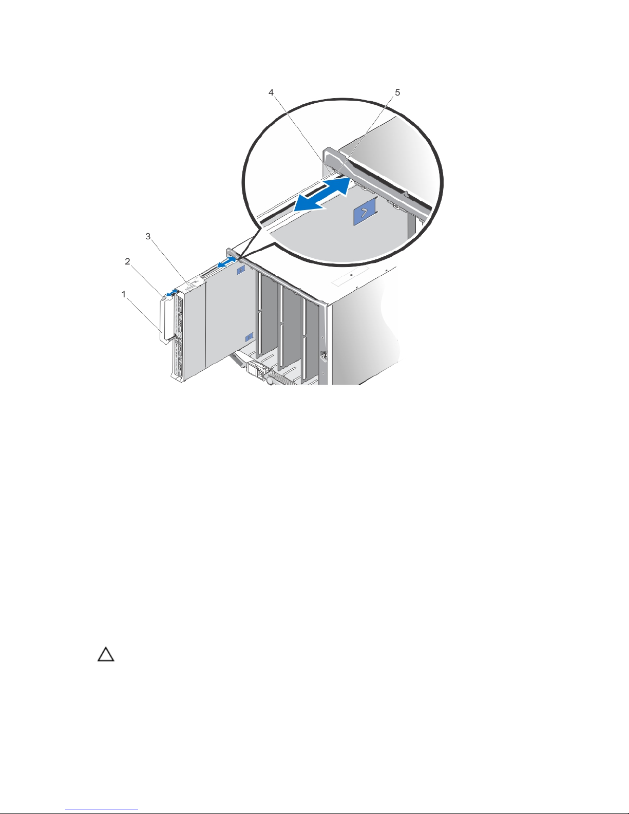
Figure 3. Removing and Installing the Blade
1. blade handle
2. release button
3. blade
4. guide rail on blade (or blade blank)
5. guide rail on enclosure
Installing A Full-Height Blade
1. If you are installing a new blade, remove the plastic cover from the I/O connectors and save for future use.
2. Orient the blade so that the handle is on the left side of the blade.
3. If you are installing the full-height blade in bays 3 or 4, rotate the LCD module to the horizontal storage position to
prevent accidental damage to the LCD screen.
4. Align the guide rail on the upper edge of the blade so that the rail fits between the plastic guides on the enclosure.
5. Slide the blade into the enclosure until the handle engages and locks the blade in place.
Opening And Closing The Blade
Opening The Blade
CAUTION: Many repairs may only be done by a certified service technician. You should only perform
troubleshooting and simple repairs as authorized in your product documentation, or as directed by the online or
telephone service and support team. Damage due to servicing that is not authorized by Dell is not covered by your
warranty. Read and follow the safety instructions that came with the product.
26
NOTE: It is recommended that you always use a static mat and static strap while working on components in the
interior of the system.
1. Remove the blade from the enclosure.
2. Install the I/O connector cover.
3. Press the release buttons and slide the cover toward the back of the blade.
4. Carefully lift the cover away from the blade.
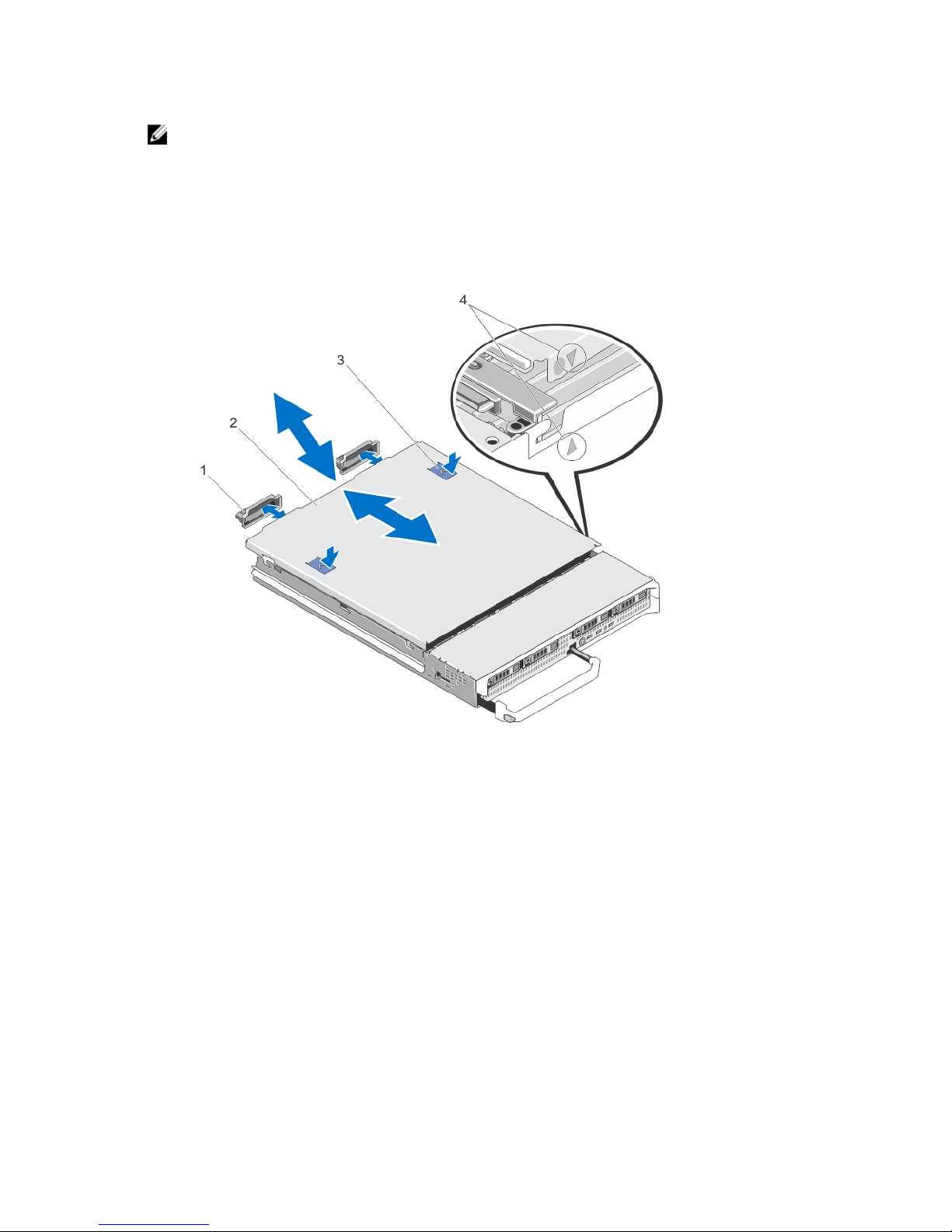
Figure 4. Opening and Closing the Blade
1. I/O connector covers (2)
2. blade cover
3. release buttons (2)
4. cover alignment pins and notches
Closing The Blade
1. Ensure that no tools or parts are left inside the blade.
2. Align the notches in the edges of the chassis with the cover alignment pins on the inner sides of the cover.
3. Lower the cover onto the chassis.
4. Slide the cover until it clicks into position.
A properly seated cover is flush with the surface of the chassis.
27
Inside The Blade
CAUTION: Many repairs may only be done by a certified service technician. You should only perform
troubleshooting and simple repairs as authorized in your product documentation, or as directed by the online or
telephone service and support team. Damage due to servicing that is not authorized by Dell is not covered by your
warranty. Read and follow the safety instructions that came with the product.
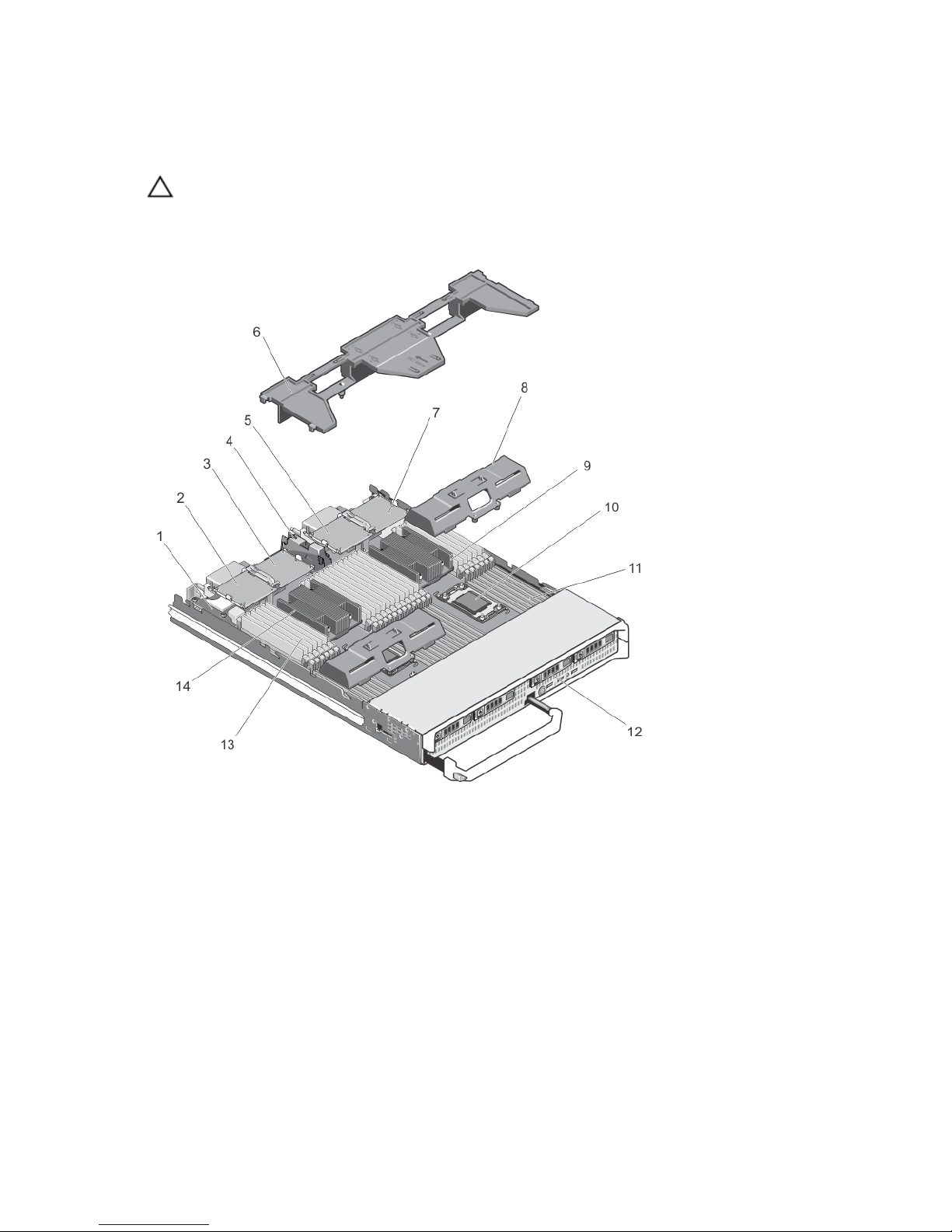
Figure 5. Inside the Blade
1. management riser card
2. optional mezzanine card 1 - Fabric C
3. optional mezzanine card 2 - Fabric B
4. mezzanine card support bracket
5. optional mezzanine card 3 - Fabric C
6. cooling shroud
7. optional mezzanine card 4 - Fabric B
8. processor/DIMM blank
9. heat sink (for processor 2)
10. processor socket 3
11. memory sockets (48)
12. hard-drives (4)
13. memory modules (48)
14. heat sink (for processor 1)
28
Cooling Shroud
The cooling shroud covers the memory modules and directs air flow in the system.
Removing The Cooling Shroud
CAUTION: Many repairs may only be done by a certified service technician. You should only perform
troubleshooting and simple repairs as authorized in your product documentation, or as directed by the online or
telephone service and support team. Damage due to servicing that is not authorized by Dell is not covered by your
warranty. Read and follow the safety instructions that came with the product.
CAUTION: Never operate your system with the cooling shroud removed. The system may get overheated quickly,
resulting in shutdown and loss of data.
1. Remove the blade from the enclosure.
2. Open the blade.
3. Hold the cooling shroud at both ends near the blade chassis and lift it up and away from the blade.
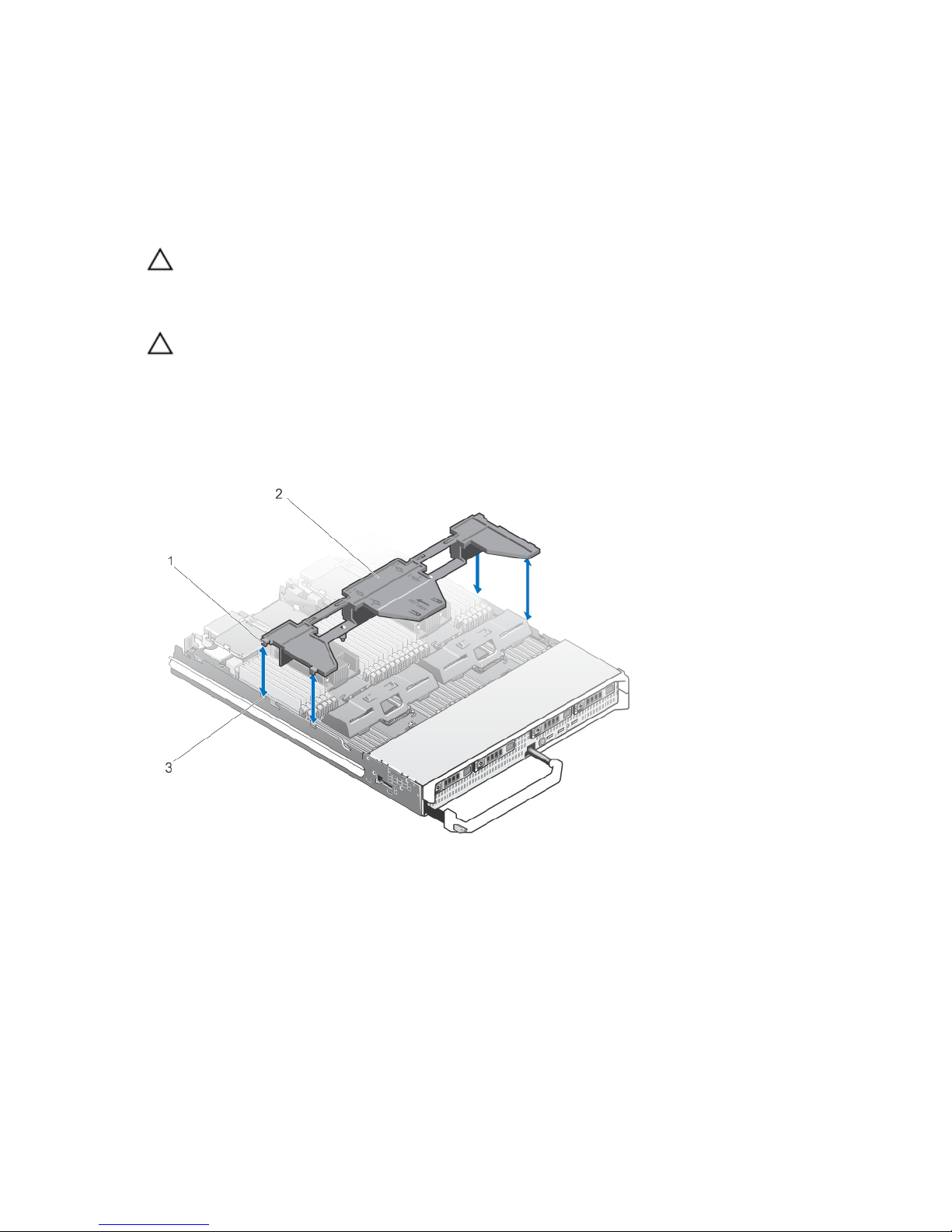
Figure 6. Removing and Installing a Cooling Shroud
1. tabs (4)
2. cooling shroud
3. slots on the chassis (4)
29

Installing The Cooling Shroud
CAUTION: Many repairs may only be done by a certified service technician. You should only perform
troubleshooting and simple repairs as authorized in your product documentation, or as directed by the online or
telephone service and support team. Damage due to servicing that is not authorized by Dell is not covered by your
warranty. Read and follow the safety instructions that came with the product.
1. Align the tabs on the cooling shroud with the slots on the chassis.
2. Lower the cooling shroud into the system until the tabs seat securely on the slots on the blade chassis.
3. Close the blade.
4. Install the blade in the enclosure.
Hard Drives/SSDs
• The system supports up to four 2.5 inch SAS hard drives or two PCIe SSDs.
• All drives connect to the system board through the SSD/SAS hard-drive backplane.
• Hard drives/PCIe SSDs are supplied in special hot-swappable drive carriers that fit in the drive slots.
• All empty drive slots must have hard-drive blanks installed.
The following table lists the supported hard drive/SSD configurations.
Table 1. Supported Hard-Drive/Controller Card/Drive Backplane Configurations
Number of
Drives
Drive Population Storage Controller Card Type
Installed
Drive Backplane Installed
Drive Bay 0 Drive Bay 1 MiniPERC
CARD
Connector
PCIe
EXTENDER
Connector
System Board
Backplane
Connector J_BP0
System Board
Backplane Connector
J_BP1
Four Two SAS
hard drives
Two SAS
hard drives
Storage
controller
card
SAS drive backplane with four drive slots
Four Two SAS
hard drives
Two PCIe
SSDs
Storage
controller
card
PCIe
extender
card
SAS hard-drive
backplane with two
drive slots
PCIe SSD backplane
with two drive slots
Two Two SAS
hard drives
- Storage
controller
card
- SAS hard-drive
backplane with two
drive slots
-
NOTE: The SAS drive backplane with four drive slots is installed on the system board connectors labeled J_BP0
and J_BP1.
NOTE: SAS hard-drive backplane (with two drive slots) for drives installed in drive bay 0 is installed on the system
board connector labeled J_BP0. The PCIe SSD backplane (with two drive slots) for PCIe SSDs is installed on the
system board connector labeled J_BP1.
NOTE: To locate J_BP0, J_BP1, MiniPERC CARD, and the PCIe EXTENDER connectors on the system board, see
System Board Connectors.
30
 Loading...